EP4538508A1 - Control method and control device for internal combustion engine - Google Patents
Control method and control device for internal combustion engine Download PDFInfo
- Publication number
- EP4538508A1 EP4538508A1 EP22945139.8A EP22945139A EP4538508A1 EP 4538508 A1 EP4538508 A1 EP 4538508A1 EP 22945139 A EP22945139 A EP 22945139A EP 4538508 A1 EP4538508 A1 EP 4538508A1
- Authority
- EP
- European Patent Office
- Prior art keywords
- oxygen storage
- storage capacity
- amount
- way catalyst
- internal combustion
- Prior art date
- Legal status (The legal status is an assumption and is not a legal conclusion. Google has not performed a legal analysis and makes no representation as to the accuracy of the status listed.)
- Withdrawn
Links
Images



Classifications
-
- F—MECHANICAL ENGINEERING; LIGHTING; HEATING; WEAPONS; BLASTING
- F01—MACHINES OR ENGINES IN GENERAL; ENGINE PLANTS IN GENERAL; STEAM ENGINES
- F01N—GAS-FLOW SILENCERS OR EXHAUST APPARATUS FOR MACHINES OR ENGINES IN GENERAL; GAS-FLOW SILENCERS OR EXHAUST APPARATUS FOR INTERNAL-COMBUSTION ENGINES
- F01N11/00—Monitoring or diagnostic devices for exhaust-gas treatment apparatus
- F01N11/007—Monitoring or diagnostic devices for exhaust-gas treatment apparatus the diagnostic devices measuring oxygen or air concentration downstream of the exhaust apparatus
-
- F—MECHANICAL ENGINEERING; LIGHTING; HEATING; WEAPONS; BLASTING
- F01—MACHINES OR ENGINES IN GENERAL; ENGINE PLANTS IN GENERAL; STEAM ENGINES
- F01N—GAS-FLOW SILENCERS OR EXHAUST APPARATUS FOR MACHINES OR ENGINES IN GENERAL; GAS-FLOW SILENCERS OR EXHAUST APPARATUS FOR INTERNAL-COMBUSTION ENGINES
- F01N3/00—Exhaust or silencing apparatus having means for purifying, rendering innocuous, or otherwise treating exhaust
- F01N3/08—Exhaust or silencing apparatus having means for purifying, rendering innocuous, or otherwise treating exhaust for rendering innocuous
- F01N3/10—Exhaust or silencing apparatus having means for purifying, rendering innocuous, or otherwise treating exhaust for rendering innocuous by thermal or catalytic conversion of noxious components of exhaust
- F01N3/101—Three-way catalysts
-
- F—MECHANICAL ENGINEERING; LIGHTING; HEATING; WEAPONS; BLASTING
- F01—MACHINES OR ENGINES IN GENERAL; ENGINE PLANTS IN GENERAL; STEAM ENGINES
- F01N—GAS-FLOW SILENCERS OR EXHAUST APPARATUS FOR MACHINES OR ENGINES IN GENERAL; GAS-FLOW SILENCERS OR EXHAUST APPARATUS FOR INTERNAL-COMBUSTION ENGINES
- F01N2550/00—Monitoring or diagnosing the deterioration of exhaust systems
- F01N2550/02—Catalytic activity of catalytic converters
-
- F—MECHANICAL ENGINEERING; LIGHTING; HEATING; WEAPONS; BLASTING
- F01—MACHINES OR ENGINES IN GENERAL; ENGINE PLANTS IN GENERAL; STEAM ENGINES
- F01N—GAS-FLOW SILENCERS OR EXHAUST APPARATUS FOR MACHINES OR ENGINES IN GENERAL; GAS-FLOW SILENCERS OR EXHAUST APPARATUS FOR INTERNAL-COMBUSTION ENGINES
- F01N2560/00—Exhaust systems with means for detecting or measuring exhaust gas components or characteristics
- F01N2560/02—Exhaust systems with means for detecting or measuring exhaust gas components or characteristics the means being an exhaust gas sensor
- F01N2560/025—Exhaust systems with means for detecting or measuring exhaust gas components or characteristics the means being an exhaust gas sensor for measuring or detecting O2, e.g. lambda sensors
-
- F—MECHANICAL ENGINEERING; LIGHTING; HEATING; WEAPONS; BLASTING
- F01—MACHINES OR ENGINES IN GENERAL; ENGINE PLANTS IN GENERAL; STEAM ENGINES
- F01N—GAS-FLOW SILENCERS OR EXHAUST APPARATUS FOR MACHINES OR ENGINES IN GENERAL; GAS-FLOW SILENCERS OR EXHAUST APPARATUS FOR INTERNAL-COMBUSTION ENGINES
- F01N2560/00—Exhaust systems with means for detecting or measuring exhaust gas components or characteristics
- F01N2560/14—Exhaust systems with means for detecting or measuring exhaust gas components or characteristics having more than one sensor of one kind
-
- F—MECHANICAL ENGINEERING; LIGHTING; HEATING; WEAPONS; BLASTING
- F01—MACHINES OR ENGINES IN GENERAL; ENGINE PLANTS IN GENERAL; STEAM ENGINES
- F01N—GAS-FLOW SILENCERS OR EXHAUST APPARATUS FOR MACHINES OR ENGINES IN GENERAL; GAS-FLOW SILENCERS OR EXHAUST APPARATUS FOR INTERNAL-COMBUSTION ENGINES
- F01N2900/00—Details of electrical control or of the monitoring of the exhaust gas treating apparatus
- F01N2900/04—Methods of control or diagnosing
- F01N2900/0412—Methods of control or diagnosing using pre-calibrated maps, tables or charts
-
- F—MECHANICAL ENGINEERING; LIGHTING; HEATING; WEAPONS; BLASTING
- F01—MACHINES OR ENGINES IN GENERAL; ENGINE PLANTS IN GENERAL; STEAM ENGINES
- F01N—GAS-FLOW SILENCERS OR EXHAUST APPARATUS FOR MACHINES OR ENGINES IN GENERAL; GAS-FLOW SILENCERS OR EXHAUST APPARATUS FOR INTERNAL-COMBUSTION ENGINES
- F01N2900/00—Details of electrical control or of the monitoring of the exhaust gas treating apparatus
- F01N2900/06—Parameters used for exhaust control or diagnosing
- F01N2900/08—Parameters used for exhaust control or diagnosing said parameters being related to the engine
-
- F—MECHANICAL ENGINEERING; LIGHTING; HEATING; WEAPONS; BLASTING
- F01—MACHINES OR ENGINES IN GENERAL; ENGINE PLANTS IN GENERAL; STEAM ENGINES
- F01N—GAS-FLOW SILENCERS OR EXHAUST APPARATUS FOR MACHINES OR ENGINES IN GENERAL; GAS-FLOW SILENCERS OR EXHAUST APPARATUS FOR INTERNAL-COMBUSTION ENGINES
- F01N2900/00—Details of electrical control or of the monitoring of the exhaust gas treating apparatus
- F01N2900/06—Parameters used for exhaust control or diagnosing
- F01N2900/14—Parameters used for exhaust control or diagnosing said parameters being related to the exhaust gas
- F01N2900/1411—Exhaust gas flow rate, e.g. mass flow rate or volumetric flow rate
-
- F—MECHANICAL ENGINEERING; LIGHTING; HEATING; WEAPONS; BLASTING
- F01—MACHINES OR ENGINES IN GENERAL; ENGINE PLANTS IN GENERAL; STEAM ENGINES
- F01N—GAS-FLOW SILENCERS OR EXHAUST APPARATUS FOR MACHINES OR ENGINES IN GENERAL; GAS-FLOW SILENCERS OR EXHAUST APPARATUS FOR INTERNAL-COMBUSTION ENGINES
- F01N2900/00—Details of electrical control or of the monitoring of the exhaust gas treating apparatus
- F01N2900/06—Parameters used for exhaust control or diagnosing
- F01N2900/16—Parameters used for exhaust control or diagnosing said parameters being related to the exhaust apparatus, e.g. particulate filter or catalyst
- F01N2900/1624—Catalyst oxygen storage capacity
-
- Y—GENERAL TAGGING OF NEW TECHNOLOGICAL DEVELOPMENTS; GENERAL TAGGING OF CROSS-SECTIONAL TECHNOLOGIES SPANNING OVER SEVERAL SECTIONS OF THE IPC; TECHNICAL SUBJECTS COVERED BY FORMER USPC CROSS-REFERENCE ART COLLECTIONS [XRACs] AND DIGESTS
- Y02—TECHNOLOGIES OR APPLICATIONS FOR MITIGATION OR ADAPTATION AGAINST CLIMATE CHANGE
- Y02T—CLIMATE CHANGE MITIGATION TECHNOLOGIES RELATED TO TRANSPORTATION
- Y02T10/00—Road transport of goods or passengers
- Y02T10/10—Internal combustion engine [ICE] based vehicles
- Y02T10/12—Improving ICE efficiencies
Definitions
- the capacity of the three-way catalyst provided in the exhaust passage of the internal combustion engine for storing oxygen at the maximum decreases with deterioration (permanent deterioration and temporary deterioration) of the catalyst. Therefore, various techniques in which the oxygen storage capacity of the three-way catalyst is determined in some manner during operation of the internal combustion engine and the catalyst deterioration is diagnosed by the extent of decrease in this actual oxygen storage capacity from an initial oxygen storage capacity have been provided (for instance, Patent Document 1).
- the initial oxygen storage capacity to be compared is, as suggested in Patent Document 1, a value set corresponding to an initial state of the three-way catalyst, i.e. characteristics of a new three-way catalyst.
- a control method of an internal combustion engine according to the present invention the internal combustion engine having a three-way catalyst in an exhaust passage and diagnosing catalyst deterioration based on decrease in an oxygen storage capacity of the three-way catalyst from a reference oxygen storage capacity, the method comprises: setting the reference oxygen storage capacity according to a flow amount of gas flowing into the three-way catalyst so that as this gas flow amount is larger, the reference oxygen storage capacity becomes smaller.
- An electronic control throttle valve 10 whose opening is controlled by a control signal from an engine controller 9 is arranged at an upstream side of a collector portion 8 in an intake passage 7 connected to the intake port 6 for each cylinder.
- An air flow meter 11 for detecting an intake air amount is arranged at an upstream side of the throttle valve 10, and an air cleaner 12 is arranged at a further upstream side.
- the three-way catalyst 15 is, for instance, a so-called monolithic ceramic catalyst in which a catalyst layer containing a catalyst metal is coated on a surface of a monolithic ceramic body having fine passages formed therein.
- the three-way catalyst 15 may have a configuration having a plurality of catalysts (e.g. a manifold catalyst and an underfloor catalyst) arranged in series.
- the internal combustion engine 1 of the embodiment is the power generating internal combustion engine in the series hybrid vehicle
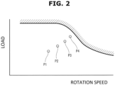
- the internal combustion engine 1 is basically started when an SOC of a vehicle travelling battery decreases, and as illustrated in Fig. 2 , the internal combustion engine 1 is operated at some operating points (combination of load and rotation speed) determined according to magnitude of power generation request.
- some operating points for instance, four operating points P1 to P4 are shown in Fig. 2 , and when the power generation request is relatively small, the internal combustion engine 1 is operated at the operating point P1 set close to the best fuel consumption point.
- the operating points P2, P3 and P4 which are located at a higher speed and higher load side, are selected. It is noted that each of these operating points is not strictly one point, but each point includes an appropriate range or region of the rotation speed and the load, although the range (or the region) is relatively narrow.
- the reference oxygen storage capacity as a reference of the deterioration judgment is set with consideration given to a flow amount of gas flowing into the three-way catalyst 15.
- a substantial oxygen storage capacity of the three-way catalyst 15 during operation is affected by the flow amount of the gas flowing into the three-way catalyst 15.
- a flow speed (or a flow rate) of the gas passing through the catalyst layer of the three-way catalyst 15 increases, then as compared with a case where the gas flow amount is small, oxygen and NOx flow out to a downstream side at a stage where the oxygen storage amount is relatively small.
- the reference oxygen storage capacity is set according to the gas flow amount so that as the gas flow amount is larger, the reference oxygen storage capacity becomes smaller.
- the intake air amount detected by the air flow meter 11 is used as a parameter corresponding to the gas flow amount into the three-way catalyst 15.
- "Intake air amount” is not an air amount per a cycle of the cylinder, but means a flow amount of air sucked into the internal combustion engine 1 (i.e. a flow amount of air passing through the air flow meter 11) per unit time.
- a perturbation control for suppressing or eliminating temporary deterioration (also referred to as temporary poisoning) of catalytic performance of the three-way catalyst 15 is included.
- the perturbation control is control that periodically repeats rich combustion with large equivalence ratio and lean combustion with small equivalence ratio. For instance, in the internal combustion engine 1 having a plurality of cylinders, the rich combustion is performed N times in succession according to combustion order, subsequently, the lean combustion is performed N times in succession, then these are periodically repeated.
- the temporary deterioration of the catalyst is a phenomenon in which a catalyst metal surface area is reduced due to adhesion of oxygen, HC etc. to a catalyst metal surface, then the catalytic performance lowers.
- the reference oxygen storage capacity calculation unit 107 determines the reference oxygen storage capacity according to the intake air amount (i.e. the gas flow amount into the three-way catalyst 15) output by the intake air amount calculation unit 101.
- the intake air amount i.e. the gas flow amount into the three-way catalyst 15
- a map of characteristics as shown in Fig. 4 in which values of the reference oxygen storage capacity are given with the intake air amount being a parameter is provided.
- the reference oxygen storage capacity according to the intake air amount is determined using this map. As illustrated in Fig. 4 , as the intake air amount is larger, the reference oxygen storage capacity becomes smaller.
- each of the oxygen storage amount and the reference oxygen storage capacity can be treated by a mass (unit "g") of oxygen.
- the oxygen storage amount when the three-way catalyst 15 is new and also the gas flow amount is the minimum is set to 100(%), and each of the oxygen storage amount and the reference oxygen storage capacity can be expressed by percentage with respect to this oxygen storage amount. Therefore, when the intake air amount is the minimum, the reference oxygen storage capacity is 100(%), and as the intake air amount is larger, the percentage becomes smaller.
- the catalyst diagnosis unit 104 judges whether the catalyst is deteriorated by comparing the current oxygen storage capacity with the reference oxygen storage capacity as described above, but as the reference oxygen storage capacity to be compared, the value of the reference oxygen storage capacity set by taking the intake air amount into consideration is used. With this, erroneous judgment, e.g . when the gas flow amount into the three-way catalyst 15 is large, is suppressed.
- the air fuel ratio control unit 105 sets the target oxygen storage amount in the air fuel ratio control using the reference oxygen storage capacity set by taking the intake air amount into consideration. For instance, a value of 1/2 of the reference oxygen storage capacity is set as the target oxygen storage amount. With this, the air fuel ratio control appropriate to an actual oxygen storage capacity changing depending on the gas flow amount can be realized.
- the rich side reset unit 110 considers that when the detected air fuel ratio of the downstream air fuel ratio sensor 20 becomes rich, the oxygen storage amount of the three-way catalyst 15 becomes 0, and resets the estimated value of the oxygen storage amount to 0.
- the intake air amount is used as the parameter corresponding to the gas flow amount into the three-way catalyst 15 (the flow amount of the gas flowing into the three-way catalyst 15).
- an exhaust gas flow amount may be calculated with consideration given to the combustion based on the intake air amount, or the exhaust gas flow amount in the exhaust passage (the flow amount of the exhaust gas flowing in the exhaust passage) might be detected by some means.
- the perturbation control is always executed at a specific operating point.
- the perturbation control may be performed when the temporary deterioration of the catalyst is detected or estimated.
Landscapes
- Engineering & Computer Science (AREA)
- Chemical & Material Sciences (AREA)
- Chemical Kinetics & Catalysis (AREA)
- Combustion & Propulsion (AREA)
- Mechanical Engineering (AREA)
- General Engineering & Computer Science (AREA)
- Materials Engineering (AREA)
- Health & Medical Sciences (AREA)
- Toxicology (AREA)
- Exhaust Gas After Treatment (AREA)
- Electrical Control Of Air Or Fuel Supplied To Internal-Combustion Engine (AREA)
Applications Claiming Priority (1)
| Application Number | Priority Date | Filing Date | Title |
|---|---|---|---|
| PCT/JP2022/023392 WO2023238361A1 (ja) | 2022-06-10 | 2022-06-10 | 内燃機関の制御方法および制御装置 |
Publications (1)
| Publication Number | Publication Date |
|---|---|
| EP4538508A1 true EP4538508A1 (en) | 2025-04-16 |
Family
ID=89117823
Family Applications (1)
| Application Number | Title | Priority Date | Filing Date |
|---|---|---|---|
| EP22945139.8A Withdrawn EP4538508A1 (en) | 2022-06-10 | 2022-06-10 | Control method and control device for internal combustion engine |
Country Status (5)
| Country | Link |
|---|---|
| US (1) | US12529330B2 (https=) |
| EP (1) | EP4538508A1 (https=) |
| JP (1) | JP7740546B2 (https=) |
| CN (1) | CN119213203A (https=) |
| WO (1) | WO2023238361A1 (https=) |
Families Citing this family (1)
| Publication number | Priority date | Publication date | Assignee | Title |
|---|---|---|---|---|
| WO2023223504A1 (ja) * | 2022-05-19 | 2023-11-23 | 日産自動車株式会社 | 三元触媒の酸素ストレージ量制御方法および装置 |
Family Cites Families (4)
| Publication number | Priority date | Publication date | Assignee | Title |
|---|---|---|---|---|
| JP2843879B2 (ja) * | 1993-01-22 | 1999-01-06 | 本田技研工業株式会社 | 内燃エンジンの触媒劣化検出装置 |
| JP2001329832A (ja) | 2000-05-22 | 2001-11-30 | Unisia Jecs Corp | 内燃機関の触媒劣化診断装置 |
| CN103249927B (zh) | 2010-12-24 | 2015-07-22 | 丰田自动车株式会社 | 内燃机的控制装置 |
| DE102016114901A1 (de) * | 2016-08-11 | 2018-02-15 | Volkswagen Aktiengesellschaft | Diagnoseverfahren und Vorrichtung zur Überprüfung der Funktionsfähigkeit einer Komponente zur Abgasnachbehandlung |
-
2022
- 2022-06-10 JP JP2024526183A patent/JP7740546B2/ja active Active
- 2022-06-10 WO PCT/JP2022/023392 patent/WO2023238361A1/ja not_active Ceased
- 2022-06-10 CN CN202280096182.XA patent/CN119213203A/zh active Pending
- 2022-06-10 EP EP22945139.8A patent/EP4538508A1/en not_active Withdrawn
- 2022-06-10 US US18/873,019 patent/US12529330B2/en active Active
Also Published As
| Publication number | Publication date |
|---|---|
| CN119213203A (zh) | 2024-12-27 |
| US12529330B2 (en) | 2026-01-20 |
| US20250354513A1 (en) | 2025-11-20 |
| WO2023238361A1 (ja) | 2023-12-14 |
| JP7740546B2 (ja) | 2025-09-17 |
| JPWO2023238361A1 (https=) | 2023-12-14 |
Similar Documents
| Publication | Publication Date | Title |
|---|---|---|
| CN101578435B (zh) | 催化剂的老化诊断装置 | |
| JP2010185325A (ja) | NOx触媒の劣化診断装置 | |
| JP2005240717A (ja) | 触媒の劣化診断装置 | |
| CN109973184B (zh) | 废气净化装置的异常诊断系统 | |
| US20120023913A1 (en) | Catalyst abnormality diagnosis apparatus | |
| JP6251143B2 (ja) | 火花点火エンジンの制御装置 | |
| JP3988518B2 (ja) | 内燃機関の排ガス浄化装置 | |
| CN109958513B (zh) | 废气净化装置的异常诊断系统 | |
| US11225896B1 (en) | Degradation diagnosis device for exhaust gas control catalyst | |
| US6467256B2 (en) | Exhaust emission control system for internal combustion engine | |
| EP4538508A1 (en) | Control method and control device for internal combustion engine | |
| JP2021116730A (ja) | 下流側空燃比検出装置の異常診断装置 | |
| CN103270282B (zh) | 内燃机的空燃比控制装置 | |
| JP3787913B2 (ja) | 内燃機関の排ガス浄化装置 | |
| JP2009150367A (ja) | 内燃機関の触媒劣化診断装置 | |
| JP2024055343A (ja) | 排気浄化触媒の劣化診断方法及び排気浄化触媒の劣化診断装置 | |
| JP4411755B2 (ja) | 排気浄化触媒の劣化状態診断装置 | |
| JP2009091921A (ja) | 内燃機関の触媒劣化診断装置 | |
| EP4582678B1 (en) | Air-fuel ratio control method and device for internal combustion engine | |
| US12037957B1 (en) | Controller for internal combustion engine | |
| US20260117719A1 (en) | Internal combustion engine system | |
| JP4688897B2 (ja) | 内燃機関の排気浄化装置 | |
| JP7718589B2 (ja) | 三元触媒の酸素ストレージ量制御方法および装置 | |
| JP3318702B2 (ja) | 内燃機関の触媒劣化診断装置 | |
| JP2005090460A (ja) | エンジンの制御装置 |
Legal Events
| Date | Code | Title | Description |
|---|---|---|---|
| STAA | Information on the status of an ep patent application or granted ep patent |
Free format text: STATUS: THE INTERNATIONAL PUBLICATION HAS BEEN MADE |
|
| PUAI | Public reference made under article 153(3) epc to a published international application that has entered the european phase |
Free format text: ORIGINAL CODE: 0009012 |
|
| STAA | Information on the status of an ep patent application or granted ep patent |
Free format text: STATUS: REQUEST FOR EXAMINATION WAS MADE |
|
| 17P | Request for examination filed |
Effective date: 20241217 |
|
| AK | Designated contracting states |
Kind code of ref document: A1 Designated state(s): AL AT BE BG CH CY CZ DE DK EE ES FI FR GB GR HR HU IE IS IT LI LT LU LV MC MK MT NL NO PL PT RO RS SE SI SK SM TR |
|
| STAA | Information on the status of an ep patent application or granted ep patent |
Free format text: STATUS: THE APPLICATION HAS BEEN WITHDRAWN |
|
| 18W | Application withdrawn |
Effective date: 20250403 |