EP4538475A1 - Verstecktes befestigungssystem für modulare paneele und erhaltene modulare struktur - Google Patents
Verstecktes befestigungssystem für modulare paneele und erhaltene modulare struktur Download PDFInfo
- Publication number
- EP4538475A1 EP4538475A1 EP23819303.1A EP23819303A EP4538475A1 EP 4538475 A1 EP4538475 A1 EP 4538475A1 EP 23819303 A EP23819303 A EP 23819303A EP 4538475 A1 EP4538475 A1 EP 4538475A1
- Authority
- EP
- European Patent Office
- Prior art keywords
- panels
- modular
- fittings
- notched
- fastening system
- Prior art date
- Legal status (The legal status is an assumption and is not a legal conclusion. Google has not performed a legal analysis and makes no representation as to the accuracy of the status listed.)
- Pending
Links
Images


Classifications
-
- E—FIXED CONSTRUCTIONS
- E04—BUILDING
- E04F—FINISHING WORK ON BUILDINGS, e.g. STAIRS, FLOORS
- E04F13/00—Coverings or linings, e.g. for walls or ceilings
- E04F13/07—Coverings or linings, e.g. for walls or ceilings composed of covering or lining elements; Sub-structures therefor; Fastening means therefor
- E04F13/21—Fastening means specially adapted for covering or lining elements
- E04F13/24—Hidden fastening means on the rear of the covering or lining elements
-
- E—FIXED CONSTRUCTIONS
- E04—BUILDING
- E04B—GENERAL BUILDING CONSTRUCTIONS; WALLS, e.g. PARTITIONS; ROOFS; FLOORS; CEILINGS; INSULATION OR OTHER PROTECTION OF BUILDINGS
- E04B2/00—Walls, e.g. partitions, for buildings; Wall construction with regard to insulation; Connections specially adapted to walls
- E04B2/74—Removable non-load-bearing partitions; Partitions with a free upper edge
-
- E—FIXED CONSTRUCTIONS
- E04—BUILDING
- E04C—STRUCTURAL ELEMENTS; BUILDING MATERIALS
- E04C2/00—Building elements of relatively thin form for the construction of parts of buildings, e.g. sheet materials, slabs, or panels
- E04C2/30—Building elements of relatively thin form for the construction of parts of buildings, e.g. sheet materials, slabs, or panels characterised by the shape or structure
- E04C2/34—Building elements of relatively thin form for the construction of parts of buildings, e.g. sheet materials, slabs, or panels characterised by the shape or structure composed of two or more spaced sheet-like parts
- E04C2/36—Building elements of relatively thin form for the construction of parts of buildings, e.g. sheet materials, slabs, or panels characterised by the shape or structure composed of two or more spaced sheet-like parts spaced apart by transversely-placed strip material, e.g. honeycomb panels
- E04C2/365—Building elements of relatively thin form for the construction of parts of buildings, e.g. sheet materials, slabs, or panels characterised by the shape or structure composed of two or more spaced sheet-like parts spaced apart by transversely-placed strip material, e.g. honeycomb panels by honeycomb structures
-
- E—FIXED CONSTRUCTIONS
- E04—BUILDING
- E04F—FINISHING WORK ON BUILDINGS, e.g. STAIRS, FLOORS
- E04F13/00—Coverings or linings, e.g. for walls or ceilings
-
- E—FIXED CONSTRUCTIONS
- E04—BUILDING
- E04F—FINISHING WORK ON BUILDINGS, e.g. STAIRS, FLOORS
- E04F13/00—Coverings or linings, e.g. for walls or ceilings
- E04F13/07—Coverings or linings, e.g. for walls or ceilings composed of covering or lining elements; Sub-structures therefor; Fastening means therefor
- E04F13/08—Coverings or linings, e.g. for walls or ceilings composed of covering or lining elements; Sub-structures therefor; Fastening means therefor composed of a plurality of similar covering or lining elements
- E04F13/0801—Separate fastening elements
- E04F13/0803—Separate fastening elements with load-supporting elongated furring elements between wall and covering elements
- E04F13/081—Separate fastening elements with load-supporting elongated furring elements between wall and covering elements with additional fastening elements between furring elements and covering elements
- E04F13/083—Hooking means on the back side of the covering elements
-
- E—FIXED CONSTRUCTIONS
- E04—BUILDING
- E04F—FINISHING WORK ON BUILDINGS, e.g. STAIRS, FLOORS
- E04F13/00—Coverings or linings, e.g. for walls or ceilings
- E04F13/07—Coverings or linings, e.g. for walls or ceilings composed of covering or lining elements; Sub-structures therefor; Fastening means therefor
- E04F13/08—Coverings or linings, e.g. for walls or ceilings composed of covering or lining elements; Sub-structures therefor; Fastening means therefor composed of a plurality of similar covering or lining elements
- E04F13/0875—Coverings or linings, e.g. for walls or ceilings composed of covering or lining elements; Sub-structures therefor; Fastening means therefor composed of a plurality of similar covering or lining elements having a basic insulating layer and at least one covering layer
-
- E—FIXED CONSTRUCTIONS
- E04—BUILDING
- E04F—FINISHING WORK ON BUILDINGS, e.g. STAIRS, FLOORS
- E04F13/00—Coverings or linings, e.g. for walls or ceilings
- E04F13/07—Coverings or linings, e.g. for walls or ceilings composed of covering or lining elements; Sub-structures therefor; Fastening means therefor
- E04F13/08—Coverings or linings, e.g. for walls or ceilings composed of covering or lining elements; Sub-structures therefor; Fastening means therefor composed of a plurality of similar covering or lining elements
- E04F13/0889—Coverings or linings, e.g. for walls or ceilings composed of covering or lining elements; Sub-structures therefor; Fastening means therefor composed of a plurality of similar covering or lining elements characterised by the joints between neighbouring elements, e.g. with joint fillings or with tongue and groove connections
- E04F13/0894—Coverings or linings, e.g. for walls or ceilings composed of covering or lining elements; Sub-structures therefor; Fastening means therefor composed of a plurality of similar covering or lining elements characterised by the joints between neighbouring elements, e.g. with joint fillings or with tongue and groove connections with tongue and groove connections
-
- B—PERFORMING OPERATIONS; TRANSPORTING
- B63—SHIPS OR OTHER WATERBORNE VESSELS; RELATED EQUIPMENT
- B63B—SHIPS OR OTHER WATERBORNE VESSELS; EQUIPMENT FOR SHIPPING
- B63B29/00—Accommodation for crew or passengers not otherwise provided for
- B63B29/02—Cabins or other living spaces; Construction or arrangement thereof
- B63B2029/027—Removable walls, e.g. for temporarily erecting cabin spaces in ship hold, or for subdividing living areas into smaller units; Fittings for removable wall panels
-
- B—PERFORMING OPERATIONS; TRANSPORTING
- B63—SHIPS OR OTHER WATERBORNE VESSELS; RELATED EQUIPMENT
- B63B—SHIPS OR OTHER WATERBORNE VESSELS; EQUIPMENT FOR SHIPPING
- B63B29/00—Accommodation for crew or passengers not otherwise provided for
- B63B29/02—Cabins or other living spaces; Construction or arrangement thereof
-
- E—FIXED CONSTRUCTIONS
- E04—BUILDING
- E04B—GENERAL BUILDING CONSTRUCTIONS; WALLS, e.g. PARTITIONS; ROOFS; FLOORS; CEILINGS; INSULATION OR OTHER PROTECTION OF BUILDINGS
- E04B1/00—Constructions in general; Structures which are not restricted either to walls, e.g. partitions, or floors or ceilings or roofs
- E04B1/38—Connections for building structures in general
- E04B1/61—Connections for building structures in general of slab-shaped building elements with each other
- E04B1/6108—Connections for building structures in general of slab-shaped building elements with each other the frontal surfaces of the slabs connected together
- E04B1/6116—Connections for building structures in general of slab-shaped building elements with each other the frontal surfaces of the slabs connected together by locking means on lateral surfaces
-
- E—FIXED CONSTRUCTIONS
- E04—BUILDING
- E04B—GENERAL BUILDING CONSTRUCTIONS; WALLS, e.g. PARTITIONS; ROOFS; FLOORS; CEILINGS; INSULATION OR OTHER PROTECTION OF BUILDINGS
- E04B2/00—Walls, e.g. partitions, for buildings; Wall construction with regard to insulation; Connections specially adapted to walls
- E04B2/74—Removable non-load-bearing partitions; Partitions with a free upper edge
- E04B2002/7461—Details of connection of sheet panels to frame or posts
-
- E—FIXED CONSTRUCTIONS
- E04—BUILDING
- E04C—STRUCTURAL ELEMENTS; BUILDING MATERIALS
- E04C2/00—Building elements of relatively thin form for the construction of parts of buildings, e.g. sheet materials, slabs, or panels
- E04C2002/001—Mechanical features of panels
- E04C2002/004—Panels with profiled edges, e.g. stepped, serrated
-
- E—FIXED CONSTRUCTIONS
- E04—BUILDING
- E04F—FINISHING WORK ON BUILDINGS, e.g. STAIRS, FLOORS
- E04F2201/00—Joining sheets or plates or panels
- E04F2201/02—Non-undercut connections, e.g. tongue and groove connections
- E04F2201/021—Non-undercut connections, e.g. tongue and groove connections with separate protrusions
- E04F2201/022—Non-undercut connections, e.g. tongue and groove connections with separate protrusions with tongue or grooves alternating longitudinally along the edge
Definitions
- the present invention relates to a hidden fastening system for panels and to the modular structure obtained, the object of which refers to a modular system for cladding and partitioning (including sectoring) spaces, both for application in industrial and civil constructions and for application in ship construction, and the modular structure of which is configured by the modular panels which are attached by means of the hidden fastening system; with said modular panels preferably being made of an aluminium material and including a configuration with a honeycomb core.
- the present invention seeks to solve all these issues in a satisfactory manner.
- the field of the art in which the present invention is comprised belongs to industrial and civil constructions, as well as to ship construction, with said constructions being carried out by means of the modular panel structure.
- Modular cladding and partitioning systems even with a structure formed by panels with a honeycomb core, are already known in the market, but they are not designed for application in ship construction, and their attachment profiles are fully visible when it is required to be able to disassemble them, which means that a projection or ribbing can be seen from the outside along the entire length of each attachment joint between each pair of panels, which negatively affects the visual finish of the formed structure as a whole.
- the invention proposes a hidden fastening system for panels and a modular structure obtained, the hidden fastening system being located along pairs of parallel opposite areas of the panels which include a first front face and a second rear face opposite the front face and edges which define the contour of said panels.
- the hidden fastening system comprises pairs of fittings formed by bases and notched structures, with the fittings being fastened to the panels by means of the bases and the notched structures being located on planes parallel to the opposite faces of the panels.
- the fittings are located in the pairs of parallel opposite areas of the panels in a location selected from a location close to the edges of the panels and a location in correspondence with the respective edges of the panels.
- the notched structures of the fittings are located in a position selected from a first position in which the notched structures project from at least one part of the edges of the panels and a second position in which the notched structures do not project from at least the part of the edges of the panels, wherein taking into consideration this second position there is a channel defined between the notched structure and a front surface of the panels which is parallel to the opposite faces of said panels.
- each hidden fastening system between each pair of adjacent panels, at least one of the two notched structures of one of the two adjacent panels is press-fitted in a channel defined between the other similar notched structure and a front surface of the other similar panel, with the edges of the two adjacent assembled panels being in contact with each other when connected.
- the teeth of the notched structures have slightly smaller dimensions than the gaps defined between said teeth, such that during the assembly of two adjacent panels to carry out their fastening, in a first phase, the teeth of one of the fittings are aligned frontally with the gaps of the other similar fitting to enable fitting at least one of the notched structures in the channel of the respective panel in a second phase.
- the fastening system between each pair of adjacent panels for a vertical cladding comprises a first fitting fastened on the rear face of one of the two panels with its notched structure projecting from the edge of said panel, and a second fitting fastened on the rear face of the other similar panel with its notched structure arranged parallel to an area of the rear face of the panel, with the channel being defined between the notched structure of the second fitting and said area of the rear face of the panel constituting the front surface.
- the fastening system between each pair of adjacent panels for a horizontal cladding comprises a first fitting fastened in correspondence with an edge having a stepped configuration of one of the two panels, and a second fitting fastened in correspondence with an edge having a stepped configuration of the other similar panel, with there being configured, between the structures of the two fittings and the front surfaces of the two panels, two channels in which the opposing structures of said panels are press-fitted, and with the edges having a stepped configuration being in contact with each other by means of a tongued and grooved coupling.
- edges having a stepped configuration comprise angular recesses and end portions, with the notched structures of the fittings being arranged parallel to the front surfaces of the end portions of the panels, and with the end portions being fitted in the angular recesses of the panels in the tongued and grooved coupling between adjacent panels.
- One panel model comprises a simple structure with a honeycomb core, with the first front faces and edges thereof being covered by laminar bodies.
- a second panel model comprises a composite structure with a honeycomb core, with the first front faces, second rear faces, and edges thereof being covered by laminar bodies.
- the modular structure obtained with the panels attached by means of the hidden fastening system comprises facings selected from vertical facings and horizontal facings of a ceiling, which are formed by a succession of panels fastened to each other by means of pairs of fittings of pairs of adjacent panels 1, 1'.
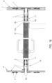
- the modular structure comprises a vertical facing of a wall which further includes a frame of a door which is fastened parallel to pairs of opposing panels with a simple structure by means of the fittings, with the frame including two parallel branches which are a continuation of the pairs of simple panels, and with fittings that are complemented with other similar fittings fastened on the pairs of panels with a simple structure being fastened on inner faces of the two parallel branches of the frame.
- the modular structure comprises a first vertical facing of a wall and two second vertical facings of collateral walls attached in a perpendicular manner to the first vertical facing, with the attachment between each collateral wall and the adjacent wall comprising pairs of panels with a simple structure with a right angle configuration formed by two flanges, with angular reinforcement profiles being assembled in the junction of the two flanges of said panels.
- the vertical facings of collateral walls comprise a composition of panels with a simple structure and panels with a composite structure.
- the modular structure includes perimeter angular profiles and an intermediate beam which supports two groups of panels with a composite structure, with the different panels of the modular horizontal structure being supported on these elements.
- the intermediate beam has an inverted T-shaped configuration, with the panels being supported on its horizontal cross member, while its vertical branch constitutes the element which separates the two groups of panels.
- the panels with a composite structure are supported, on one of their opposite faces, on the horizontal cross member of the intermediate beam and on a flange of the perimeter angular profiles.
- the panels with a composite structure are supported on the perimeter angular profiles through the end portions located in opposite areas of said panels in correspondence with one of the branches of the angular recesses of the opposite edges of the panels.
- the two opposing end portions of two panels with a composite structure converging at a central area are supported on the horizontal cross member of the intermediate beam, while one of the two panels further includes an additional extension which covers a gap of the same width as said horizontal cross member and as the sum of the two opposing end portions of the two panels.
- the hidden fastening system of the invention is applicable to claddings and partitions for spaces and is essentially designed with aluminium panels with a honeycomb core.
- the aluminium structure with a honeycomb core of the panels makes them much lighter compared to other materials such as steel, mortars, or plaster, all this without reducing the rigidity necessary to enable the use thereof as cladding or partitioning element, even providing them with greater structural capacities and offering the possibility of increasing the size of the panels, thereby reducing the number of joints and thus favouring better cleaning.
- the hidden fastening system as means for attaching said panels is of the plug-and-play type.
- the fastening system comprises the structure-format hidden fittings located on the rear face of each panel with a simple structure.
- Each vertical panel is easily assembled in two movements, a first forward movement to the front in order to place it vertically in its position, and another downward movement so that the respective structure is fastened in the corresponding channel.
- each panel can be disassembled again individually by simply performing the same movements as for the assembly, but in reverse, that is, lifting the panel and pulling it frontally backwards and towards itself.
- fittings being designed to be hidden is that they allow attachment without additional profiles, and therefore the exterior visual finish is smooth and projection-free, with a single line of attachment in correspondence with the contact of their edges, which also allows the subsequent lining of these partitions with other textures or materials, such as wood, PVC, laminates, etc.
- the tongued and grooved coupling of the edges of adjacent panels is a stepped Z-shaped coupling, with one panel (slat) being supported on another adjacent panel, which allows them to be easily disassembled.
- the panel When fastening against partitions, the panel is designed to be supported on the respective contour profile, the latter being hidden by the inside of the ceiling panel. This design of the attachment to the support profiles also allows each panel (slat) to be disassembled individually without having to disassemble the adjoining panels.
- the material used for manufacturing the elements complies with the "SOLAS" fire regulations for use in ship construction as class "C” partitions.
- the elements of the invention are manufactured with non-combustible materials and their use is also valid for naval applications.
- the modular structure comprises panels 1, 1' which are configured for engagement with each other by means of the hidden fastening system located along pairs of parallel opposite areas of said panels 1, 1' in correspondence with pairs of opposite edges of the panels 1, 1', with the panels 1, 1' comprising a honeycomb core in the embodiment shown in the figures.
- Each panel 1, 1' includes two opposite faces: a visible front face and a rear face opposite the front face and both faces converge at the side edges or borders of the panel 1, 1'.
- the hidden fastening system comprises pairs of fittings 2, each of which comprises an elongated profile including a base 2a which is fastened to the panels 1, 1' by means of fastening elements 3, and a notched structure 2b.
- Said fastening elements 3 can be rivets as shown in the figures, screws, by means of an adhesive, or any other fastening means.
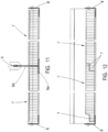
- the modular structure is applicable for assembling first claddings arranged on vertical planes (vertical partitions) such as, for example, the one shown in Figures 15 , 16 , 17, and 18 , and second claddings arranged on horizontal planes or inclined planes for roof coverings (horizontal partitions) as shown in Figures 11 to 14 .
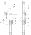
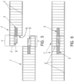
- the panels 1 comprise a first simple structure having a smaller thickness ( Figures 3, 4 , 9 , and 16 ), and in another embodiment of the invention, the panels 1' comprise a second composite structure 1' having a greater thickness ( Figures 5, 6 , 10 , 11, 12 , 13, 14 , and 16 ).
- each panel 1 with a simple structure the pair of fittings 2 is fastened on their rear face that will be hidden, with the notched rack 2b in one of the two fittings 2 projecting from the edge of the panel 1, while the other similar fitting 2 being tucked inwards, taking as a reference the other similar edge of the panel 1.
- Said notched structures 2b are arranged parallel to the opposite faces of the panel 1 with a simple structure.
- the notched structure 2b of the fitting 2 projecting from one of the two panels 1 occupies a channel 5 defined between the other similar notched structure 2b and the rear face of the other similar panel.
- both panels 1 are then moved relatively to each other so that the teeth of both notched structures 2b are in contact with each other with a certain tightness, thereby ensuring engagement.
- the assembled panels are in contact with each other at their adjacent edges, while being flush with each other on their respective opposite faces: front and rear opposite faces.
- the panel 1 which is moved is usually the one assembled on the previously assembled panel 1 or group of previously assembled panels 1.
- each panel 1' with a composite structure the pair of fittings 2 is fastened on the two opposite edges of the panel 1', such that the bases 2a of the fittings 2 are hidden in the actual structure of the panel 1'.
- each of its two opposing edges where the fittings 2 are fastened comprises a stepped configuration formed by an angular recess 6 and a complementary end portion 7, with the notched structure 2b of the fitting 2 being arranged parallel to the end portion 7 of the panel 1'.
- the notched structures 2b are arranged parallel to the opposite faces of the panel 1' with a composite structure, and at the same time also arranged parallel to and in proximity to the end portions 7 of said composite panel 1'.
- channels 5' configured for fitting therein the notched structures 2b of said panels 1' in a conjugated manner.
- the end portion 7 of one panel 1' is coupled by way of tongued and grooved in the angular recess 6 of another adjacent panel 1' following the same methodology or procedure as for the simple panels 1 described above, such that once the notched structures 2b are located in the channels 5', the panels 1' are then moved relatively to each other so that the teeth of both notched structures 2b are in contact with each other with a certain tightness, thereby ensuring engagement.
- the assembled panels 1' with a composite structure are in contact with each other at their adjacent edges with a stepped configuration, while said panels 1' being flush with each other on their respective opposite faces: front and rear opposite faces.
- the panel 1' with a composite structure which is moved is usually the one assembled on the previously assembled panel 1' or group of previously assembled panels 1.
- said modular horizontal structure further includes perimeter angular profiles 8 and an intermediate beam 9 separating and supporting two groups of panels 1' with a composite structure, with the different panels 1' (slats) of the modular horizontal structure being supported on these elements 8 and 9.
- the intermediate beam 9 has an inverted T-shaped configuration, with the panels 1' being supported on its horizontal cross member 9a, while its vertical branch 9b constitutes the element which separates the two groups of panels 1'.
- the panels 1' with a composite structure are supported on the horizontal cross member 9a of the intermediate beam 9 and on a flange of the perimeter angular profiles 8.
- the panels 1' with a composite structure are supported on the perimeter angular profiles 8 through the end portions 7 located in opposite areas of said panels 1' in correspondence with one of the branches of the angular recesses 6 of the opposite edges of the panels 1'.
- two opposing end portions 7 of two panels 1' with a composite structure converging at a central area are supported on the horizontal cross member 9a of the intermediate beam 9, while one of the two panels 1' further includes an additional extension 10 that covers a gap of the same width as said horizontal cross member 9a and as the sum of the two opposing end portions 7 of the two panels 1'.
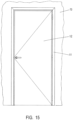
- the hidden system of the invention is also applicable to the installation of frames 11 of doors 12.
- the frame 11 has a C-shaped section, with its cross member 11a defining the gap where the door 12 is located, while its two opposite and parallel branches 11b are a continuation of end segments of pairs of parallel panels 1 with a simple structure constituting a wall 13 (vertical cladding) in which the door 12 is installed along with its frame 11.
- Said Figure 16 also shows two collateral vertical walls 14 (vertical claddings) which are attached to the wall 13 in which the door 12 is installed, such that pairs of panels 1 with a simple structure with a right-angle configuration are used in the attachment between each collateral wall 14 and the wall 13 of the door 12, such that angular reinforcement profiles 15 are assembled in the junction of the two branches of said panels.
- collateral walls 14 comprise a combination of panels 1 with a simple structure and panels 1' made of composite panels.
- FIG. 1 depicts the fittings 2 before being fastened and Figure 2 depicts the fittings 2 once they have slide vertically and are fastened to each other in a complementary manner.
- Figures 3 to 6 show the sections of what is depicted in Figures 1 and 2 but using different panel thicknesses: smaller thickness (panels 1 with a simple structure) with the structure on the rear face of the panel and greater panel thickness (panels 1' with a composite structure) with the notched structure 2b on the inside in correspondence with the edges having a stepped configuration of the panels 1'.
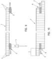
- FIGs 7 , 8 , 9, and 10 show the hidden fastening fastened in the panel 1, 1'.
- fastening is performed on the hidden rear face thereof ( Figures 7 and 8 ); while in the thicker panel 1' ( Figures 9 and 10 ), the fastening is fastened on the inside in correspondence with its opposite edges having a stepped configuration.
- Figures 11 to 14 fundamentally show two applications of the invention on ceilings for horizontal claddings, formed by the honeycomb core and with hidden fastening design compatible with the overall system, with the panels 1' (slats) being supported on profiles described above such as the perimeter angular profiles 8 and the intermediate beams 9, such that they are hidden or flush with each other on the entire outer surface of the panels 1'.
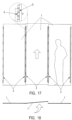
- Figures 17 and 18 show an example of assembling a cladding of modular panel 1 with the hidden fastening system. It can be seen how the panel 1 can be fastened and disassembled with ease in two movements.
- the fastening with a hidden structure allows keeping the panels 1 fastened to each other without requiring additional profiles, conferring a smoother and cleaner finish. Being structural, it allows disassembling each panel 1 individually without having to disassemble the entire line of panels 1.
- the hidden fastening system is also applicable to the frames 11 of doors 12, with the design of the frame 11 being adapted to allow the also modular fastening thereof, which allows the ability to completely replace a door 12 at any time, also including the frame 11 itself, without affecting the rest of the claddings or partitions.
- the invention is designed to cover, partition, or sector a space in its entirety, as can be seen in the figures, with the individual disassembly of each panel 1, 1' being possible and minimising the profiles and corners on the visible front face, without losing the preceding advantages in any case.
Landscapes
- Engineering & Computer Science (AREA)
- Architecture (AREA)
- Civil Engineering (AREA)
- Structural Engineering (AREA)
- Physics & Mathematics (AREA)
- Electromagnetism (AREA)
- Joining Of Building Structures In Genera (AREA)
- Connection Of Plates (AREA)
Applications Claiming Priority (2)
| Application Number | Priority Date | Filing Date | Title |
|---|---|---|---|
| ES202230504A ES2957489B2 (es) | 2022-06-09 | 2022-06-09 | Sistema de anclaje oculto de paneles modulares y estructura modular obtenida |
| PCT/ES2023/070346 WO2023237792A1 (es) | 2022-06-09 | 2023-05-26 | Sistema de anclaje oculto de paneles modulares y estructura modular obtenida |
Publications (2)
| Publication Number | Publication Date |
|---|---|
| EP4538475A1 true EP4538475A1 (de) | 2025-04-16 |
| EP4538475A4 EP4538475A4 (de) | 2025-10-08 |
Family
ID=89117788
Family Applications (1)
| Application Number | Title | Priority Date | Filing Date |
|---|---|---|---|
| EP23819303.1A Pending EP4538475A4 (de) | 2022-06-09 | 2023-05-26 | Verstecktes befestigungssystem für modulare paneele und erhaltene modulare struktur |
Country Status (3)
| Country | Link |
|---|---|
| EP (1) | EP4538475A4 (de) |
| ES (1) | ES2957489B2 (de) |
| WO (1) | WO2023237792A1 (de) |
Family Cites Families (11)
| Publication number | Priority date | Publication date | Assignee | Title |
|---|---|---|---|---|
| US3488908A (en) * | 1967-07-12 | 1970-01-13 | Chicago Metallic Corp | Concealed grid ceiling structure and panel therefor providing accessibility |
| US3613329A (en) * | 1969-06-18 | 1971-10-19 | Orbit International Inc | Panel post joining means |
| GB8817632D0 (en) * | 1988-07-23 | 1988-09-01 | Hunting Eng Ltd | Quick release joint |
| US5546720A (en) * | 1995-03-10 | 1996-08-20 | Color & Design Exhibits | Panel assembly system |
| ATE348920T1 (de) * | 2000-02-02 | 2007-01-15 | Skyline Displays Inc | Paneel-verbindungssystem |
| GB0701290D0 (en) * | 2007-01-24 | 2007-02-28 | Smith Martin A | Joints and structures |
| EP2631380B1 (de) * | 2012-02-23 | 2015-03-18 | Saint-Gobain Ecophon AB | Abgehängte Decke, Deckenelement und zugehöriges Montageverfahren |
| TWM452682U (zh) * | 2012-11-01 | 2013-05-11 | Toshihiro Hayashi | 簡易輕便隔間構件 |
| EP2796637A1 (de) * | 2013-04-25 | 2014-10-29 | Profile VOX Sp. z o.o. Sp. K | Siding-Art-Profile und die Art und Weise der Verbindung von Anschlussgleis-type Profile |
| KR102164970B1 (ko) * | 2020-01-22 | 2020-10-13 | 강준기 | 칸막이 결착 장치 및 이를 이용한 사무실 칸막이 |
| CN214617328U (zh) * | 2020-12-28 | 2021-11-05 | 浙江亚厦装饰股份有限公司 | 一种铝蜂窝板拼接机构 |
-
2022
- 2022-06-09 ES ES202230504A patent/ES2957489B2/es active Active
-
2023
- 2023-05-26 EP EP23819303.1A patent/EP4538475A4/de active Pending
- 2023-05-26 WO PCT/ES2023/070346 patent/WO2023237792A1/es not_active Ceased
Also Published As
| Publication number | Publication date |
|---|---|
| ES2957489A1 (es) | 2024-01-19 |
| WO2023237792A1 (es) | 2023-12-14 |
| EP4538475A4 (de) | 2025-10-08 |
| ES2957489B2 (es) | 2024-11-11 |
Similar Documents
| Publication | Publication Date | Title |
|---|---|---|
| EP0102825B1 (de) | System für eine demontierbare Trennwand | |
| US8127505B2 (en) | Assembly type wall structure | |
| KR102039324B1 (ko) | 내화 칸막이 보강벽체의 시공구조 및 그 시공방법 | |
| US8316606B2 (en) | Fastening system for panels and trim | |
| CA2954845C (en) | Wall panel connecting system for modular building units | |
| GB2600285A (en) | Prefabricated frames for masonry slips | |
| KR102192046B1 (ko) | 칸막이 연결구조 | |
| RU2339775C1 (ru) | Способ крепления фасадных плит | |
| EP4538475A1 (de) | Verstecktes befestigungssystem für modulare paneele und erhaltene modulare struktur | |
| US2054189A (en) | Building construction | |
| US3535842A (en) | Fire-resistant removable wall panel | |
| RU2213832C2 (ru) | Способ построения офисных перегородок | |
| US20200131761A1 (en) | Wall system | |
| WO2020227290A1 (en) | Curtain wall frame gaskets | |
| EP0534789B1 (de) | Universelle Türzarge | |
| GB2526771A (en) | Ceiling track | |
| CN114207228B (zh) | 一种租用间分隔系统 | |
| CN116692640B (zh) | 一种侧后一段踢脚线的装潢轿厢 | |
| EP1582642A2 (de) | Trennwand | |
| KR102940167B1 (ko) | 건물 외장용 유리 패널 시스템 | |
| US20240352731A1 (en) | System and method for a modular ceiling grid beam that supports construction of a controlled environment or catwalk | |
| EP4459069A1 (de) | Gebäudewand | |
| SU806523A1 (ru) | Судовое помещение | |
| RU2684541C1 (ru) | Система крепления панелей | |
| US20090188191A1 (en) | Panelization Method and System |
Legal Events
| Date | Code | Title | Description |
|---|---|---|---|
| STAA | Information on the status of an ep patent application or granted ep patent |
Free format text: STATUS: THE INTERNATIONAL PUBLICATION HAS BEEN MADE |
|
| PUAI | Public reference made under article 153(3) epc to a published international application that has entered the european phase |
Free format text: ORIGINAL CODE: 0009012 |
|
| STAA | Information on the status of an ep patent application or granted ep patent |
Free format text: STATUS: REQUEST FOR EXAMINATION WAS MADE |
|
| 17P | Request for examination filed |
Effective date: 20241121 |
|
| AK | Designated contracting states |
Kind code of ref document: A1 Designated state(s): AL AT BE BG CH CY CZ DE DK EE ES FI FR GB GR HR HU IE IS IT LI LT LU LV MC ME MK MT NL NO PL PT RO RS SE SI SK SM TR |
|
| DAV | Request for validation of the european patent (deleted) | ||
| DAX | Request for extension of the european patent (deleted) | ||
| A4 | Supplementary search report drawn up and despatched |
Effective date: 20250908 |
|
| RIC1 | Information provided on ipc code assigned before grant |
Ipc: E04B 2/74 20060101AFI20250902BHEP Ipc: E04F 13/00 20060101ALI20250902BHEP Ipc: E04F 13/24 20060101ALI20250902BHEP |