EP4537973A1 - Kraftfahrzeugkomponente und verfahren zu deren herstellung - Google Patents
Kraftfahrzeugkomponente und verfahren zu deren herstellung Download PDFInfo
- Publication number
- EP4537973A1 EP4537973A1 EP23203268.0A EP23203268A EP4537973A1 EP 4537973 A1 EP4537973 A1 EP 4537973A1 EP 23203268 A EP23203268 A EP 23203268A EP 4537973 A1 EP4537973 A1 EP 4537973A1
- Authority
- EP
- European Patent Office
- Prior art keywords
- component
- wall
- wall thickness
- end section
- bevel
- Prior art date
- Legal status (The legal status is an assumption and is not a legal conclusion. Google has not performed a legal analysis and makes no representation as to the accuracy of the status listed.)
- Granted
Links
Images


Classifications
-
- B—PERFORMING OPERATIONS; TRANSPORTING
- B23—MACHINE TOOLS; METAL-WORKING NOT OTHERWISE PROVIDED FOR
- B23K—SOLDERING OR UNSOLDERING; WELDING; CLADDING OR PLATING BY SOLDERING OR WELDING; CUTTING BY APPLYING HEAT LOCALLY, e.g. FLAME CUTTING; WORKING BY LASER BEAM
- B23K33/00—Specially-profiled edge portions of workpieces for making soldering or welding connections; Filling the seams formed thereby
- B23K33/002—Crimping or bending the workpieces at the joining area
-
- B—PERFORMING OPERATIONS; TRANSPORTING
- B21—MECHANICAL METAL-WORKING WITHOUT ESSENTIALLY REMOVING MATERIAL; PUNCHING METAL
- B21D—WORKING OR PROCESSING OF SHEET METAL OR METAL TUBES, RODS OR PROFILES WITHOUT ESSENTIALLY REMOVING MATERIAL; PUNCHING METAL
- B21D53/00—Making other particular articles
- B21D53/88—Making other particular articles other parts for vehicles, e.g. cowlings, mudguards
-
- B—PERFORMING OPERATIONS; TRANSPORTING
- B23—MACHINE TOOLS; METAL-WORKING NOT OTHERWISE PROVIDED FOR
- B23K—SOLDERING OR UNSOLDERING; WELDING; CLADDING OR PLATING BY SOLDERING OR WELDING; CUTTING BY APPLYING HEAT LOCALLY, e.g. FLAME CUTTING; WORKING BY LASER BEAM
- B23K33/00—Specially-profiled edge portions of workpieces for making soldering or welding connections; Filling the seams formed thereby
- B23K33/004—Filling of continuous seams
- B23K33/008—Filling of continuous seams for automotive applications
-
- B—PERFORMING OPERATIONS; TRANSPORTING
- B23—MACHINE TOOLS; METAL-WORKING NOT OTHERWISE PROVIDED FOR
- B23K—SOLDERING OR UNSOLDERING; WELDING; CLADDING OR PLATING BY SOLDERING OR WELDING; CUTTING BY APPLYING HEAT LOCALLY, e.g. FLAME CUTTING; WORKING BY LASER BEAM
- B23K37/00—Auxiliary devices or processes, not specially adapted for a procedure covered by only one of the other main groups of this subclass
-
- B—PERFORMING OPERATIONS; TRANSPORTING
- B60—VEHICLES IN GENERAL
- B60G—VEHICLE SUSPENSION ARRANGEMENTS
- B60G21/00—Interconnection systems for two or more resiliently-suspended wheels, e.g. for stabilising a vehicle body with respect to acceleration, deceleration or centrifugal forces
- B60G21/02—Interconnection systems for two or more resiliently-suspended wheels, e.g. for stabilising a vehicle body with respect to acceleration, deceleration or centrifugal forces permanently interconnected
- B60G21/04—Interconnection systems for two or more resiliently-suspended wheels, e.g. for stabilising a vehicle body with respect to acceleration, deceleration or centrifugal forces permanently interconnected mechanically
- B60G21/05—Interconnection systems for two or more resiliently-suspended wheels, e.g. for stabilising a vehicle body with respect to acceleration, deceleration or centrifugal forces permanently interconnected mechanically between wheels on the same axle but on different sides of the vehicle, i.e. the left and right wheel suspensions being interconnected
- B60G21/051—Trailing arm twist beam axles
-
- B—PERFORMING OPERATIONS; TRANSPORTING
- B23—MACHINE TOOLS; METAL-WORKING NOT OTHERWISE PROVIDED FOR
- B23K—SOLDERING OR UNSOLDERING; WELDING; CLADDING OR PLATING BY SOLDERING OR WELDING; CUTTING BY APPLYING HEAT LOCALLY, e.g. FLAME CUTTING; WORKING BY LASER BEAM
- B23K2101/00—Articles made by soldering, welding or cutting
- B23K2101/006—Vehicles
-
- B—PERFORMING OPERATIONS; TRANSPORTING
- B23—MACHINE TOOLS; METAL-WORKING NOT OTHERWISE PROVIDED FOR
- B23K—SOLDERING OR UNSOLDERING; WELDING; CLADDING OR PLATING BY SOLDERING OR WELDING; CUTTING BY APPLYING HEAT LOCALLY, e.g. FLAME CUTTING; WORKING BY LASER BEAM
- B23K2103/00—Materials to be soldered, welded or cut
- B23K2103/02—Iron or ferrous alloys
- B23K2103/04—Steel or steel alloys
-
- B—PERFORMING OPERATIONS; TRANSPORTING
- B60—VEHICLES IN GENERAL
- B60G—VEHICLE SUSPENSION ARRANGEMENTS
- B60G2200/00—Indexing codes relating to suspension types
- B60G2200/20—Semi-rigid axle suspensions
- B60G2200/21—Trailing arms connected by a torsional beam, i.e. twist-beam axles
-
- B—PERFORMING OPERATIONS; TRANSPORTING
- B60—VEHICLES IN GENERAL
- B60G—VEHICLE SUSPENSION ARRANGEMENTS
- B60G2206/00—Indexing codes related to the manufacturing of suspensions: constructional features, the materials used, procedures or tools
- B60G2206/01—Constructional features of suspension elements, e.g. arms, dampers, springs
- B60G2206/70—Materials used in suspensions
- B60G2206/72—Steel
-
- B—PERFORMING OPERATIONS; TRANSPORTING
- B60—VEHICLES IN GENERAL
- B60G—VEHICLE SUSPENSION ARRANGEMENTS
- B60G2206/00—Indexing codes related to the manufacturing of suspensions: constructional features, the materials used, procedures or tools
- B60G2206/01—Constructional features of suspension elements, e.g. arms, dampers, springs
- B60G2206/80—Manufacturing procedures
- B60G2206/82—Joining
- B60G2206/8201—Joining by welding
Definitions
- the invention relates to a motor vehicle component according to the features in the preamble of claim 1 and to a method for producing a welded motor vehicle component according to the features in the preamble of claim 8.
- Welding is a design-defining manufacturing process for welded components and one of the most important and widely used joining processes, particularly in automotive engineering. Welding is the permanent, material-to-material joining of components using heat and pressure, with or without filler metals. In joint welding, the parts are joined to form the welded component by weld seams at the welded joint. Several welded components form a welded assembly, and several welded assemblies form a welded structure.
- Welding joins components or component sections together in such a way that they can meet the requirements placed on them over their expected service life. To achieve this, the welded joints must meet appropriate quality criteria and characteristics. These are closely linked to the specific component requirements in use. Adequate quality can be expected if irregularities in the weld seam that occur during or after welding can be tolerated for the use of the welded component.
- the weld joint is the area where the welded parts are joined.
- the weld design and position have a decisive influence on the functionally relevant parameters of the weld, such as penetration.
- the penetration depth is the distance between the surface of the base material molten by welding and the original surface of the base material, i.e., the depth of the molten zone in the base material.
- the penetration depth is closely related to the joint strength. Weld strength and weld quality are particularly important for automotive components that are subject to high levels of stress during operation.
- the invention is based on the object of improving the load behavior of a motor vehicle component welded from at least two components and increasing its service life without adversely increasing the weight, and of demonstrating a method for producing a welded motor vehicle component with an improved welding result.
- the joining surface at the end section of the first component has a bevel produced without cutting.
- the end section of the first component receives seam preparation optimized for welding.
- the joining surface is extended by the bevel section.
- the bevel in the joining surface of the end section gives the joining gap between the joining surface of the first component and the joining surface on the second component a V-shaped configuration.
- the joining gap between the end section of the first component and the second component has a V-shaped configuration.
- the bevel and the V-shaped joining gap result in very good penetration in the first component.
- Penetration is the depth of the molten zone in the base material.
- the invention improves penetration, particularly in the first component. A component-optimized and process-improved penetration is created in the first component without burn-through in the thinner wall of the second component.
- the invention creates a motor vehicle component with a longer service life without increasing the component weight.
- the welded joint between the two components is highly stable and exhibits optimized static and, in particular, dynamic load behavior.
- the motor vehicle component according to the invention is in particular a chassis component such as axles, in particular a twist beam axle.
- twist beam axle with a first component in the form of a torsion profile and second components in the form of side arms or trailing arms.
- Motor vehicle components of the type according to the invention can be all welded constructions in which at least two components with different wall thicknesses are connected by a welded joint, in particular with a T-, L- or X-joint.
- the wall of the first component and the wall of the second component can have the same wall thickness.
- the wall thicknesses of the first component and the second component can also differ from one another.
- the invention is particularly advantageous for motor vehicle components in which the first component has a wall with a wall thickness that is greater than the wall thickness of a wall of the second component. Furthermore, it is possible for the first component to have a wall with a wall thickness that is smaller than the wall thickness of the wall of the second component.
- the bevel and the V-shaped joint gap ensure a high penetration in the first component, i.e. the component with the thicker or stronger wall.
- the invention reliably ensures a penetration of 2% to 10% with a flank penetration of 70% to 90%.
- the invention enables a penetration of up to 30% to be reliably achieved. Practical tests suggest even higher penetration values, so that penetration can be increased to more than 50%.
- the bevel provided by the invention allows welding filler material to be pushed between the components in the joint gap during welding, so that the root of the weld seam is moved further or deeper into the joint gap. This results in significantly higher penetration.
- the bevel can extend along the entire joint edge of a motor vehicle component.
- the bevel is provided in the areas of the joint edge where the greatest loads from external forces occur.
- the bevel is provided in particular at the joining surfaces of the legs of the torsion profile.
- the bevel is arranged on the inside of the torsion profile along the legs.
- the bevel can also be provided only over a partial section of the length of the joining surface at the end section of the first component.
- the bevel is formed starting from a free end of the wall of the first component over a length section of approximately 30% to 75%, in particular approximately 50%, of the length of the wall of the first component.
- the bevel can be arranged on the inside of the cross-section on the inside of the torsion profile on the legs.
- the bevel can be arranged on the outside of the cross-section on the outside of the torsion profile along the legs.
- the tangential length of the bevel is measured in the cross-section of the torsion profile in the direction of the circumference of the torsion profile and can extend over the entire circumferential length of the end face of the torsion profile. However, the tangential length of the bevel can also extend only over the length of one leg or be provided on a partial section of the length of one leg of a torsion profile.
- the slope runs at an angle to the longitudinal axis of the wall of the first component. The angle is preferably in a range between 25° and 60°. In practice, an angle in the range of 30° to 45° is considered particularly advantageous.
- the abutment surface runs essentially perpendicular to the longitudinal axis of the torsion profile wall.
- the abutment surface is where the first component butts against the second component.
- One aspect of the invention provides that the abutting surface has a width measured at right angles to the longitudinal axis of the wall of the first component, which is greater than the wall thickness of the wall of the first component.
- the bevel of the joining surface runs into the front face of the end section.
- the butt surface is connected to the bevel.
- the bevel of the joining surface at the end section of the first component is created without cutting.
- a controlled plastic deformation is performed at the end section of the first component.
- the end section is brought into the desired shape by applying an external force. This is achieved, in particular, by bending or shear forming.
- the end section is laterally shifted, bent, or deformed during forming. As already explained above, this is achieved, in particular, by bending or shear forming.
- the end section of the original blank can first be formed into an S shape.
- the end section is then trimmed, and an end piece is separated from the free end of the end section.
- the trimming is performed at right angles to the longitudinal axis of the original blank or the wall of the original blank.
- a slight chamfer is created, particularly on the side of the counterholder of the cutting tool. Consequently, the trimming line is not straight but has a slightly angled chamfer or surface at the end of the trimming line.
- the end-side trimming of the end section takes place at an angle transversely, in particular substantially at right angles to the longitudinal axis of the wall of the output board.
- the first component and the second component have different wall thicknesses.
- the wall thickness of the second component is, at least in some regions, less than the wall thickness of the first component in the region of the joint connection.
- a second component is provided which has a wall with a wall thickness that differs from the wall thickness of the wall of the first component.
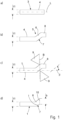
- the Figure 1a shows an output board 3.
- the output board 3 has a wall 4 with a wall thickness t1.
- An end section 5 of the initial blank 3 is formed without cutting.
- the end section 5 is plastically deformed and configured in an S-shape. This creates a leg 6 with a bevel 7 and an end piece 8 running parallel to the longitudinal axis L of the wall 4 of the initial blank 3. This is shown in the illustration of the Figure 1b ).
- the end piece 8 is displaced laterally parallel to the longitudinal axis L of the wall 4.
- the Figure 1c illustrates the trimming operation on end section 5. End trimming is performed on end section 5.
- the cutting tool is identified by reference numeral 9. The trimming is performed at an angle perpendicular to the longitudinal axis L of wall 4 of the output board 3 along trim line B.
- the trimming operation takes place in the area of the leg 6 with the bevel 7. During trimming, the end piece 8 is removed. A butt surface 10 is created on the end section 5, running perpendicular to the longitudinal axis L.
- the Figure 1d shows the finished trimmed first component 1.
- the bevel 7 has an axial length l.
- the axial length l of the bevel 7 is measured in the direction of the longitudinal axis L of the wall 4 of the torsion profile 1.
- the axial length l is measured in the area of the later joint connection.
- the bevel 7 runs at an angle ⁇ of 25° to 60°, in particular of 30° to 45°, to the longitudinal axis L of the wall 4 of the first component 1.
- the ratio of the axial length l of the bevel 7 to the wall thickness t1 of the wall of the first component 1 is between 1:1 and 1:5.
- the bevel 7 is located on the side of the end section 5 of the first component, which forms the acute angle ⁇ with the second component 11.
- a second component 11 made of steel is provided.
- the second component 11 has a wall 12 with a wall thickness t2.
- the wall thickness t1 of the wall 4 of the first component 1 is greater than the wall thickness t2 of the wall 12 of the second component 11.
- the first component 1 has a joining surface 13 at the end section 5.
- the joining surface 13 includes the bevel 7 and the end-face abutment surface 10.
- the second component 11 also has a joining surface 14.
- the first component 1 and the second component 11 are joined by a welded joint. To create the welded joint, the first component 1 and the second component 11 are positioned relative to each other. This is shown in the illustration of the Figure 2a ). The first component 1 and the second component 11 are arranged at an angle ⁇ to each other, in particular the first component 1 butts against the second component 11 at a right angle ⁇ with a T-joint.
- the joining surface 13 of the first component 1 and the joining surface 14 of the second component 11 face each other.
- the abutting surface 10 runs at a right angle to the longitudinal axis L of the wall 4 of the first component 1.
- the abutting surface 10 is oriented parallel to the joining surface 14 of the second component 11.
- a V-shaped joining gap 15 is formed between the joining surface 13 of the first component 1 and the joining surface 14 of the second component 11.
- the bevel 7 runs at an acute angle to the end face 17.
- the bevel 7 ends at the end face 17.
- the abutting surface 10 adjoins the bevel 7 at an obtuse angle.
- the material-to-material joining connection is made via a weld seam 18, as shown in the Figure 2b ). Due to the bevel 7 and the V-shaped joint gap 15, the weld seam 18 is efficient, whereby a high penetration in the first component 1 is achieved.
- the penetration of the weld seam 18 on the first component 1 can be significantly increased without causing burn-through on the second component 11.
- the weld seam 18 meets the highest strength requirements, thereby increasing the overall service life of the motor vehicle component 2 without increasing its overall weight.
- the motor vehicle component 2 is, in particular, a twist-beam axle.
- a first component 1 in the form of a torsion profile is welded at each end to a second component 11 in the form of a side arm.
- the Figure 3 shows a motor vehicle component 2 in the form of a twist beam axle with a first component 1, which is the torsion profile, and second components 11, each of which is a side arm of the twist beam axle.
- the torsion profile has a wall 4 with a wall thickness t1.
- Each side arm has a wall 12 with a wall thickness t2.
- the wall thickness t1 of the wall 4 of the torsion profile can be greater than the wall thickness t2 of a side arm.
- the explanations regarding the illustrations in the Figures 1 and 2 is referred to.
- the torsion profile has a U-shaped cross-section with two side legs 19 connected by an apex section 20.
- the end section 5 of the torsion profile abuts the wall 12 of a side arm.
- the joining surface 13 at the end section 5 of the torsion profile is adapted to the outer contour of the wall 12 of the side arm.
- the arrow P2 indicates the length of a longitudinal section 21 of the first component 1 or of a side leg 19, in which the bevel 7 is provided on the inside of the side leg 19.
- the bevel 7 is provided in the lower longitudinal section 21 of the side leg 19.
- the bevel 7 extends over two-thirds, in particular approximately half, of the length of a side leg 19. Relative to the cross-section of a side arm, the bevel 7 extends over a circumferential section of approximately 90° +/- 15°.
- the bevel 7 is provided in the lower longitudinal section 21 of a side leg 19, starting from the free leg end.
- the Figure 4 shows a front view of the joining surface 13 at an end section 5 of a first component 1 in the form of a torsion profile.
- the torsion profile has a wall 4 with a wall thickness t1.
- In the joining surface 13 at the end section 5 of the A bevel 7 produced according to the invention is provided on the torsion profile.
- the bevel 7 runs on the inside of the side legs 19 of the torsion profile.
- the bevel 7 is provided in the lower longitudinal section 21 of the side leg 19, extending from the free leg end.
- the tangential length of the longitudinal section 21 is indicated by the arrow P2.
- the bevel 7 extends approximately over half the length of a side leg 19.
- the Figure 5 shows a front view of the joining surface 13 in an alternative embodiment at the end section 5 of a torsion profile 1.
- the bevel 7 is arranged on the outside of the side legs 19 of the torsion profile.
- the bevel 7 is produced by machining.
- the bevel 7 extends in a lower longitudinal section 21 of each side leg 19, starting from the free leg end. Otherwise, the embodiment corresponds to that of Figure 4 and the corresponding description.
Landscapes
- Engineering & Computer Science (AREA)
- Mechanical Engineering (AREA)
- Physics & Mathematics (AREA)
- Optics & Photonics (AREA)
- Butt Welding And Welding Of Specific Article (AREA)
- Body Structure For Vehicles (AREA)
Abstract
Description
- Die Erfindung betrifft eine Kraftfahrzeugkomponente gemäß den Merkmalen im Oberbegriff von Anspruch 1 sowie ein Verfahren zur Herstellung einer geschweißten Kraftfahrzeugkomponente gemäß den Merkmalen im Oberbegriff von Anspruch 8.
- Schweißen ist ein die Gestaltung bestimmendes Fertigungsverfahren für Schweißbauteile und eines der wichtigsten und am weitesten verbreiteten Fügeverfahren, insbesondere im Automobilbau. Unter Schweißen versteht man das unlösbare stoffschlüssige Verbinden von Bauteilen unter Anwendung von Wärme und Druck mit oder ohne Schweißzusatzwerkstoffen. Beim Verbindungsschweißen werden die Teile durch Schweißnähte am Schweißstoß zum Schweißbauteil zusammengefügt. Mehrere Schweißbauteile ergeben eine Schweißgruppe und mehrere Schweißgruppen eine Schweißkonstruktion.
- Durch Schweißen werden die Bauteile bzw. Bauteilabschnitte so miteinander verbunden, dass diese die an sie gestellten Anforderungen über eine erwartete Lebensdauer erfüllen können. Dazu müssen die Schweißverbindungen anforderungsgerechte Qualitätskriterien und Gütemerkmale erfüllen. Diese sind eng mit den an die jeweiligen Bauteilanforderungen im Einsatz gebunden. Ausreichende Qualität ist dann zu erwarten, wenn auftretende Unregelmäßigkeiten der Schweißnaht, die während oder nach dem Schweißen entstehen, für die Nutzung des geschweißten Bauteils toleriert werden können.
- Als Schweißstoß wird der Bereich bezeichnet, in dem die Schweißteile miteinander vereinigt werden. Am Schweißstoß hat die Schweißnahtausführung und die Schweißnahtlage einen entscheidenden Einfluss auf die funktionsrelevanten Parameter der Schweißnaht, wie zum Beispiel den Einbrand. Als Einbrandtiefe bezeichnet man den Abstand der Oberfläche des durch Schweißen geschmolzenen Grundwerkstoffs und der ursprünglichen Oberfläche des Grundwerkstoffs, also die Tiefe der aufgeschmolzenen Zone im Grundwerkstoff.
- Die Einbrandtiefe steht in engem Zusammenhang mit der Fügefestigkeit. Insbesondere bei Kraftfahrzeugkomponenten, die während des Fahrens hoch beansprucht werden, kommt der Festigkeit der Schweißnähte und der Schweißnahtqualität besondere Bedeutung zu.
- Der Erfindung liegt ausgehend vom Stand der Technik die Aufgabe zugrunde, eine aus zumindest zwei Bauteilen geschweißte Kraftfahrzeugkomponente im Belastungsverhalten zu verbessern und in der Lebensdauer zu steigern, ohne das Gewicht nachteilig zu erhöhen sowie ein Verfahren zur Herstellung einer geschweißten Kraftfahrzeugkomponente aufzuzeigen mit einem verbesserten Schweißergebnis.
- Die Lösung des gegenständlichen Teils der Aufgabe besteht nach der Erfindung in einer Kraftfahrzeugkomponente gemäß Anspruch 1.
- Der verfahrensmäßige Teil der Aufgabe wird durch ein Verfahren gemäß Anspruch 8 gelöst.
- Vorteilhafte Weiterbildungen und Ausgestaltungen der erfindungsgemäßen Kraftfahrzeugkomponente ebenso wie des erfindungsgemäßen Verfahrens sind Gegenstand der abhängigen Ansprüche.
- Eine erfindungsgemäße Kraftfahrzeugkomponente weist ein erstes Bauteil und ein zweites Bauteil auf. Die beiden Bauteile bestehen aus Stahl und sind schweißtechnisch mittels zumindest einer Schweißnaht verbunden. Das erste Bauteil weist eine Wand mit einer Wandstärke auf und das zweite Bauteil weist eine Wand mit einer Wandstärke auf. Das erste Bauteil und das zweite Bauteil weisen jeweils eine Fügefläche auf. Die beiden Bauteile sind in einem Winkel zueinander angeordnet und an den einander zugewandten Fügeflächen durch eine Schweißnaht verbunden.
- Erfindungsgemäß weist die Fügefläche am Endabschnitt des ersten Bauteils eine spanlos gefertigte Schräge auf.
- Der Endabschnitt des ersten Bauteils erhält eine auf die schweißtechnische Fügung optimierte Nahtvorbereitung. Die Fügefläche wird durch den Abschnitt der Schräge verlängert. Durch die Schräge in der Fügefläche des Endabschnitts erhält der Fügespalt zwischen der Fügefläche des ersten Bauteils und der Fügefläche am zweiten Bauteil eine V-förmige Konfiguration. Der Fügespalt zwischen dem Endabschnitt des ersten Bauteils und dem zweiten Bauteil ist V-förmig konfiguriert. Durch die Schräge und den V-förmigen Fügespalt ist ein sehr guter Einbrand im ersten Bauteil erreicht. Als Einbrand bezeichnet man die Tiefe der aufgeschmolzenen Zone im Grundwerkstoff. Die Erfindung verbessert den Einbrand, insbesondere im ersten Bauteil. Es wird ein bauteiloptimierter und verfahrenstechnisch verbesserter Einbrand im ersten Bauteil erzeugt, ohne dass es zu einem Durchbrand in der dünneren Wand des zweiten Bauteils kommt.
- Die Erfindung schafft eine Kraftfahrzeugkomponente mit höherer Lebensdauer ohne eine Erhöhung des Bauteilgewichts. Die schweißtechnische Fügung zwischen den beiden Bauteilen ist hochstabil und weist ein optimiertes statisches und insbesondere dynamisches Belastungsverhalten auf.
- Bei der erfindungsgemäßen Kraftfahrzeugkomponente handelt es sich insbesondere um Fahrwerkskomponenten wie Achsen, insbesondere eine Verbundlenkerachse.
- Insbesondere handelt es sich um eine Verbundlenkerachse mit einem ersten Bauteil in Form eines Torsionsprofils und zweiten Bauteilen in Form von Seitenarmen bzw. Längslenkern.
- Kraftfahrzeugkomponenten der erfindungsgemäßen Art können alle Schweißkonstruktionen sein, bei denen zumindest zwei Bauteile mit unterschiedlichen Wandstärken durch eine Schweißverbindung, insbesondere mit einem T-, L- oder einem X-Stoß verbunden sind.
- Die Wand des ersten Bauteils und die Wand des zweiten Bauteils können eine gleich große Wandstärke besitzen. Die Wandstärken von erstem Bauteil und zweitem Bauteil können auch voneinander verschieden sein. Die Erfindung ist besonders vorteilhaft für Kraftfahrzeugkomponenten, bei welchen das erste Bauteil eine Wand mit einer Wandstärke aufweist, die größer ist als die Wandstärke einer Wand des zweiten Bauteils. Weiterhin ist es möglich, dass das erste Bauteil eine Wand mit einer Wandstärke aufweist, die kleiner ist als die Wandstärke der Wand des zweiten Bauteils.
- Insbesondere bei geschweißten Kraftfahrzeugkomponenten aus Bauteilen mit voneinander verschiedenen Wandstärken hat sich gezeigt, dass es wegen des Wandstärkenunterschieds schwierig ist, einen hohen Einbrand der Schweißnaht in das dickere Bauteil, also das Bauteil mit der größeren Wandstärke zu erhalten, ohne dass es zu einem Durchbrand an dem Bauteil mit geringerer Wandstärke kommt. Durch den geringeren Einbrand kann es zu einer Reduzierung der Lebensdauer der geschweißten Kraftfahrzeugkomponente kommen.
- Durch die Schräge und den V-förmigen Fügespalt wird ein hoher Einbrand im ersten Bauteil, also dem Bauteil mit der dickeren bzw. stärken Wand, gewährleistet.
- Durch die Erfindung wird ein Einbrand von 2 % bis 10 % sicher gewährleistet mit einer Flankeneinbrandlänge von 70 % bis 90 %. Insbesondere ermöglicht die Erfindung einen Einbrand von bis zu 30 % prozesssicher zu erreichen. Praktische Versuche lassen noch höhere Werte für den Einbrand erwarten, so dass der Einbrand bis auf größer 50 % gesteigert werden kann.
- Durch die erfindungsgemäß vorgesehene Schräge kann beim Schweißen Schweißzusatzwerkstoff zwischen die Bauteile im Fügespalt geschoben werden, so dass die Wurzel der Schweißnaht weiter bzw. tiefer in den Fügespalt verlagert wird. In der Folge ergibt sich ein deutlich höherer Einbrand.
- Die Schräge kann sich entlang einer gesamten Stoßkante eines Kraftfahrzeugbauteils erstecken. Insbesondere ist die Schräge in den Bereichen einer Stoßkante vorgesehen, in welchen die größten Belastungen durch äußere Kräfte auftreten. Bei einem Torsionsprofil einer Verbundlenkerachse ist die Schräge insbesondere an den Fügeflächen der Schenkel des Torsionsprofils vorgesehen. Bei einem im Querschnitt U- oder V-förmigen Torsionsprofil ist die Schräge auf der Innenseite des Torsionsprofils entlang der Schenkel angeordnet.
- Die Schräge kann auch nur auf einem Teilabschnitt der Länge der Fügefläche am Endabschnitt des ersten Bauteils vorgesehen sein. Insbesondere ist die Schräge von einem freien Ende der Wand des ersten Bauteils ausgehend über einen Längenabschnitt von ca. 30 % bis 75 %, insbesondere von ca. 50 %, der Länge der Wand des ersten Bauteils ausgebildet. Bei einem im Querschnitt U- oder V-förmigen Torsionsprofil kann die Schräge innenseitig des Querschnitts auf der Innenseite des Torsionsprofils an den Schenkeln angeordnet sein. Weiterhin kann die Schräge außenseitig des Querschnitts auf der Außenseite des Torsionsprofils entlang der Schenkel angeordnet sein.
- Die tangentiale Länge der Schräge ist im Querschnitt des Torsionsprofils in Richtung des Umfangs des Torsionsprofils gemessen und kann sich über die gesamte Umfangslänge der Stirnseite des Torsionsprofils erstrecken. Die tangentiale Länge der Schräge kann aber auch nur über die Länge eines Schenkels verlaufen oder auf einem Teilabschnitt der Länge eines Schenkels eines Torsionsprofils vorgesehen sein
Die Schräge verläuft in einem Winkel zur Längsachse der Wand des ersten Bauteils. Vorzugsweise liegt der Winkel in einem Bereich zwischen 25° bis 60°. Für die Praxis vorteilhaft wird insbesondere ein Winkel im Bereich von 30° bis 45° angesehen. - Die Fügefläche des ersten Endabschnitts weist vorzugsweise eine stirnseitige Stoßfläche auf. Die Stoßfläche befindet stirnseitig am freien Ende des Endabschnitts.
- Die Stoßfläche verläuft im Wesentlichen rechtwinklig zur Längsachse der Wand des Torsionsprofils. Mit der Stoßfläche stößt das erste Bauteil stumpf gegen das zweite Bauteil.
- Ein Aspekt der Erfindung sieht vor, dass die Stoßfläche eine rechtwinklig zur Längsachse der Wand des ersten Bauteils gemessene Breite aufweist, welche größer ist als die Wandstärke der Wand des ersten Bauteils.
- Die Schräge der Fügefläche läuft in die Stirnseite des Endabschnitts aus. An die Schräge schließt sich die Stoßfläche an.
- Erfindungsgemäß ist die Schräge der Fügefläche am Endabschnitt des ersten Bauteils spanlos erzeugt. Hierzu wird eine gesteuerte plastische Formänderung am Endabschnitt des ersten Bauteils vorgenommen. Der Endabschnitt wird durch Aufbringen einer äußeren Kraft in die gewünschte Form gebracht. Dies erfolgt insbesondere durch Biegeumformen oder Schubumformen.
- Das erfindungsgemäße Verfahren zur Herstellung einer geschweißten Kraftfahrzeugkomponente, welche zumindest zwei Bauteile aus Stahl mit unterschiedlicher Wandstärke aufweist, die in einem Winkel zueinander angeordnet und durch eine Schweißnaht verbunden sind, weist folgende Schritte auf:
- Fertigen eines ersten Bauteils mit einer Fügefläche, welche eine Schräge und eine Stoßfläche aufweist, wozu
- eine Ausgangsplatine bereitgestellt wird, welche eine Wand mit einer Wandstärke aufweist und
- ein Endabschnitt der Ausgangsplatine umgeformt und am Endabschnitt eine Schräge ausgebildet wird und
- der Endabschnitt endseitig beschnitten und stirnseitig am Endabschnitt eine Stoßfläche erzeugt wird;
- Bereitstellen eines zweiten Bauteils, welches eine Wand mit einer Wandstärke besitzt und das zweite Bauteil eine Fügefläche aufweist;
- Positionieren des ersten Bauteils und des zweiten Bauteils in einem Winkel relativ zueinander, so dass die Fügefläche des ersten Bauteils und die Fügefläche des zweiten Bauteils einander zugewandt sind;
- Stoffschlüssige Fügung des ersten Bauteils und des zweiten Bauteils durch eine Schweißnaht an den Fügeflächen.
- Insbesondere wir der Endabschnitt beim Umformen seitlich verschoben, gebogen oder verprägt. Dies erfolgt wie bereits vorstehend ausgeführt, insbesondere durch Biegeumformen oder Schubumformen.
- Zur Herstellung der Schräge am Endabschnitt kann der Endabschnitt der Ausgangsplatine zunächst S-förmig umgeformt werden. Anschließend wird der Endabschnitt beschnitten und ein Endstück am freien Ende des Endabschnitts von diesem abgetrennt. Der Beschnitt erfolgt rechtwinklig zur Längsachse der Ausgangsplatine bzw. der Wand der Ausgangsplatine. Beim Beschnittvorgang wird insbesondere auf der Seite des Gegenhalters des Schneidwerkzeugs eine leichte Fase erzeugt. Die Beschnittlinie verläuft folglich nicht geradlinig sondern weist am Ende der Beschnittlinie eine geringfügig schräg verlaufende Fase bzw. Fläche auf.
- Die Ausgangsplatine kann vor oder nach dem Umformen und Beschneiden des Endabschnitts einer weiteren Umformung unterzogen werden. Bei diesem Umformschritt erhält die Ausgangsplatine, zumindest bereichsweise, insbesondere über ihre Länge eine Querschnittskonfiguration des ersten Bauteils.
- Weiterhin ist vorgesehen, dass der endseitige Beschnitt des Endabschnitts in einem Winkel quer, insbesondere im Wesentlichen rechtwinklig zur Längsachse der Wand der Ausgangsplatine erfolgt.
- Im Rahmen der Erfindung ist insbesondere vorgesehen, dass das erste Bauteil und das zweite Bauteil voneinander verschiedene Wandstärken besitzen. Insbesondere ist die Wandstärke des zweiten Bauteils zumindest bereichsweise geringer als die Wandstärke des ersten Bauteils im Bereich der Fügeverbindung. Dementsprechend wird ein zweites Bauteil bereitgestellt, welches eine Wand mit einer Wandstärke besitzt, welche von der Wandstärke der Wand des ersten Bauteils verschieden ist.
- Die Erfindung ist nachfolgenden anhand von Zeichnungen näher beschrieben. Es zeigen:
- Figur 1a) bis d)
- technisch schematisiert die Vorgehensweise zur Fertigung eines ersten Bauteils mit einer Fügefläche, welche eine Schräge und eine Stoßfläche aufweist;
- Figur 2a)
- einen Ausschnitt aus der Wand eines ersten Bauteils und einen Ausschnitt aus der Wand eines zweiten Bauteils vor der schweißtechnischen Fügung;
- Figur 2b)
- die Bauteile entsprechend der Darstellung der
Figur 2a ) nach der schweißtechnischen Fügung; - Figur 3
- eine Verbundlenkerachse in einer perspektivischen Darstellung;
- Figur 4
- eine Ansicht auf die Stirnseite des Endabschnitts eines Torsionsprofils einer Verbundlenkerachse und
- Figur 5
- eine Ansicht auf die Stirnseite des Endabschnitts einer weiteren Ausführungsform eines Torsionsprofils.
- Anhand der
Figuren 1a ) bis d) ist der Umformprozess zur Herstellung eines ersten Bauteils 1 einer Kraftfahrzeugkomponente 2 erläutert. Die Kraftfahrzeugkomponente 2 ist in derFigur 2b ) dargestellt. - Die
Figur 1a ) zeigt eine Ausgangsplatine 3. Die Ausgangsplatine 3 weist eine Wand 4 mit einer Wandstärke t1 auf. - Ein Endabschnitt 5 der Ausgangsplatine 3 wird spanlos umgeformt. Hierbei wird der Endabschnitt 5 plastisch verformt und S-förmig konfiguriert. Auf diese Weise entsteht am Endabschnitt 5 ein Schenkel 6 mit einer Schräge 7 und ein parallel zur Längsachse L der Wand 4 der Ausgangsplatine 3 verlaufendes Endstück 8. Dies zeigt die Darstellung der
Figur 1b ). Das Endstück 8 ist seitlich parallel zur Längsachse L der Wand 4 verschoben. - Die
Figur 1c ) verdeutlicht die Beschnittoperation am Endabschnitt 5. Am Endabschnitt 5 wird ein endseitiger Beschnitt vorgenommen. Das Schneidwerkzeug ist mit dem Bezugszeichen 9 gekennzeichnet. Der Beschnitt erfolgt in einem Winkel rechtwinklig zur Längsachse L der Wand 4 der Ausgangsplatine 3 entlang der Beschnittlinie B. - Die Beschnittoperation erfolgt im Bereich des Schenkels 6 mit der Schräge 7. Beim Beschnitt wird das Endstück 8 entfernt. Stirnseitig am Endabschnitt 5 wird eine rechtwinklig zur Längsachse L verlaufende Stoßfläche 10 erzeugt.
- Die
Figur 1d ) zeigt das fertig beschnittene erste Bauteil 1. - Die Stoßfläche 10 weist eine rechtwinklig zur Längsachse L der Wand 4 des ersten Bauteils 1 gemessene Breite b auf, welche größer ist als die Wandstärke t1 der Wand 4 des ersten Bauteils 1. Das Verhältnis der Wandstärke t1 der Wand 4 des ersten Bauteils 1 zur Breite b der Stoßfläche 10 ist zwischen 1:1,1 und 1:1,5 bemessen.
- Die Schräge 7 weist eine axiale Länge l auf. Die axiale Länge I der Schräge 7 ist in Richtung der Längsachse L der Wand 4 des Torsionsprofils 1 gemessen. Die axiale Länge l ist gemessen im Bereich der späteren Fügeverbindung. Die Schräge 7 verläuft in einem Winkel β von 25° bis 60°, insbesondere von 30° bis 45° zur Längsachse L der Wand 4 des ersten Bauteils 1. Das Verhältnis der axialen Länge l der Schräge 7 zur Wandstärke t1 der Wand des ersten Bauteils 1 ist zwischen 1:1 und 1:5 bemessen. Die Schräge 7 befindet sich auf der Seite des Endabschnitts 5 des ersten Bauteils, welches mit dem zweiten Bauteil 11 den spitzen Winkel β einschließt.
- Zur Herstellung des Kraftfahrzeugbauteils wird ein zweites Bauteil 11 aus Stahl bereitgestellt. Das zweite Bauteil 11 weist eine Wand 12 mit einer Wandstärke t2 auf. Die Wandstärke t1 der Wand 4 des ersten Bauteils 1 ist größer als die Wandstärke t2 der Wand 12 des zweiten Bauteils 11.
- Das erste Bauteil 1 weist am Endabschnitt 5 eine Fügefläche 13 auf. Die Fügefläche 13 umfasst die Schräge 7 und die stirnseitige Stoßfläche 10.
- Das zweite Bauteil 11 weist ebenfalls eine Fügefläche 14 auf.
- Das erste Bauteil 1 und zweite Bauteil 11 werden durch eine Schweißverbindung stoffschlüssig gefügt. Zur Herstellung der Schweißverbindung werden das erste Bauteil 1 und das zweite Bauteil 11 zueinander positioniert. Dies zeigt die Darstellung der
Figur 2a ). Das erste Bauteil 1 und das zweite Bauteil 11 sind in einem Winkel α zueinander angeordnet, insbesondere stößt das erste Bauteil 1 stumpf in einen rechten Winkel α mit T-Stoß an das zweite Bauteil 11. - Die Fügefläche 13 des ersten Bauteils 1 und die Fügefläche 14 des zweiten Bauteils 11 sind einander zugewandt. Die Stoßfläche 10 verläuft rechtwinklig zur Längsachse L der Wand 4 des ersten Bauteils 1. Die Stoßfläche 10 ist parallel zur Fügefläche 14 des zweiten Bauteils 11 orientiert. Zwischen der Fügefläche 13 des ersten Bauteils 1 und der Fügefläche 14 des zweiten Bauteils 11 ist ein V-förmiger Fügespalt 15 gebildet. Im Tiefsten des V-förmigen Fügespalts 15 schließt sich ein parallel zwischen der Stoßfläche 10 und der Fügefläche 14 des zweiten Bauteils 11 ausgebildeter Spaltabschnitt 16 an. Die Schräge 7 verläuft in einem spitzen Winkel zur Stirnseite 17 hin. An der Stirnseite 17 endet die Schräge 7. Die Stoßfläche 10 schließt sich mit einem stumpfen Winkel an die Schräge 7 an.
- Die stoffschlüssige Fügeverbindung erfolgt über eine Schweißnaht 18, wie in der
Figur 2b ) dargestellt. Durch die Schräge 7 und den V-förmig konfigurierten Fügespalt 15 wird die Schweißnaht 18 effizient, wobei ein hoher Einbrand im ersten Bauteil 1 erreicht wird. - Durch die Nahtvorbereitung und die Ausbildung der Schräge 7 in der Fügefläche 13 am ersten Bauteil 1 sowie die V-förmige Konfiguration des Fügespalts 15 entsteht eine Schweißverbindung zwischen erstem Bauteil 1 und zweitem Bauteil 11 mit einer anforderungsgerechten Qualität und Lebensdauer. Der Einbrand der Schweißnaht 18 am ersten Bauteil 1 kann deutlich erhöht werden ohne dass es zu einem Durchbrand am zweiten Bauteil 11 kommt. Die Schweißnaht 18 genügt höchsten Festigkeitsanforderungen, wodurch insgesamt die Lebensdauer der Kraftfahrzeugkomponente 2 erhöht werden kann, ohne diese im Gesamtgewicht zu erhöhen.
- Bei der Kraftfahrzeugkomponente 2 handelt es sich insbesondere um eine Verbundlenkerachse. Bei der Verbundlenkerachse wird ein erstes Bauteil 1 in Form eines Torsionsprofils jeweils endseitig mit einem zweiten Bauteil 11 in Form eines Seitenarms schweißtechnisch gefügt.
- Die
Figur 3 zeigt eine Kraftfahrzeugkomponente 2 in Form einer Verbundlenkerachse mit einem ersten Bauteil 1, bei dem es sich um das Torsionsprofil handelt, und zweiten Bauteilen 11, bei denen es sich jeweils um einen Seitenarm der Verbundlenkerachse handelt. Das Torsionsprofil weist eine Wand 4 mit einer Wandstärke t1 auf. Jeder Seitenarm weist eine Wand 12 mit einer Wandstärke t2 auf. Die Wandstärke t1 der Wand 4 des Torsionsprofils kann größer als die Wandstärke t2 eines Seitenarms sein. Auf die Ausführungen zu den Darstellungen in denFiguren 1 und2 wird verwiesen. Das Torsionsprofil hat einen U-förmigen Querschnitt mit zwei Seitenschenkeln 19, die über einen Scheitelabschnitt 20 verbunden sind. Mit dem Endabschnitt 5 stößt das Torsionsprofil an die Wand 12 eines Seitenarms. Die Fügefläche 13 am Endabschnitt 5 des Torsionsprofils ist an die Außenkontur der Wand 12 des Seitenarms angepasst. - Durch den Pfeil P1 ist schematisch die Länge eines Seitenschenkels 19 verdeutlicht, mit welchem der Endabschnitt 5 des ersten Bauteils 1 bzw. des Torsionsprofils am Außenumfang eines Seitenarms anstößt. Dieser beträgt bezogen auf den Umfang des im Querschnitt runden Seitenarms etwa 180° +/- 15°.
- Durch den Pfeil P2 ist die Länge eines Längenabschnitts 21 des ersten Bauteils 1 bzw. eines Seitenschenkels 19 verdeutlicht, in welchem die Schräge 7 auf der Innenseite des Seitenschenkels 19 vorgesehen ist. Die Schräge 7 ist im unteren Längenabschnitt 21 des Seitenschenkels 19 vorgesehen. Insbesondere erstreckt sich die Schräge 7 über zwei Drittel, insbesondere ca. der Hälfte der Länge eines Seitenschenkels 19. Bezogen auf den Querschnitt eines Seitenarms erstreckt sich die Schräge 7 auf einen Umfangsabschnitt von ca. 90° +/- 15°. Die Schräge 7 ist vom freien Schenkelende ausgehend im unteren Längenabschnitt 21 eines Seitenschenkels 19 vorgesehen.
- Die
Figur 4 zeigt eine Stirnansicht auf die Fügefläche 13 an einem Endabschnitt 5 eines ersten Bauteils 1 in Form eines Torsionsprofils. Das Torsionsprofil weist eine Wand 4 mit einer Wandstärke t1 auf. In der Fügefläche 13 am Endabschnitt 5 des Torsionsprofils ist eine erfindungsgemäß erzeugte Schräge 7 vorgesehen. Die Schräge 7 verläuft innenseitig der Seitenschenkel 19 des Torsionsprofils. - Die Schräge 7 ist in dem vom freien Schenkelende ausgehenden unteren Längenabschnitt 21 des Seitenschenkels 19 vorgesehen. Die tangentiale Länge des Längenabschnitts 21 ist durch den Pfeil P2 gekennzeichnet. Im dargestellten Ausführungsbeispiel erstreckt sich die Schräge 7 etwa über die Hälfte der Länge eines Seitenschenkels 19.
- Die
Figur 5 zeigt eine Stirnansicht auf die Fügefläche 13 in einer alternativen Ausgestaltung am Endabschnitt 5 eines Torsionsprofils 1. Anders als bei der Ausführungsform gemäß derFigur 4 ist hier die Schräge 7 außenseitig der Seitenschenkel 19 des Torsionsprofils angeordnet. Die Schräge 7 ist wie auch bei den anderen Ausführungsformen durch spanende Bearbeitung erzeugt. Die Schräge 7 erstreckt sich in einem vom freien Schenkelende ausgehenden unteren Längenabschnitt 21 eines jeden Seitenschenkels 19. Ansonsten entspricht die Ausführungsform derjenigen derFigur 4 und die zugehörige Beschreibung. -
- 1 -
- erstes Bauteil
- 2 -
- Kraftfahrzeugkomponente
- 3 -
- Ausgangsplatine
- 4 -
- Wand
- 5 -
- Endabschnitt
- 6 -
- Schenkel
- 7 -
- Schräge
- 8 -
- Endstück
- 9 -
- Schneidwerkzeug
- 10 -
- Stoßfläche
- 11 -
- zweites Bauteil
- 12 -
- Wand
- 13 -
- Fügefläche
- 14 -
- Fügefläche
- 15 -
- Fügespalt
- 16 -
- Spaltabschnitt
- 17 -
- Stirnseite
- 18 -
- Schweißnaht
- 19 -
- Seitenschenkel
- 20 -
- Scheitelabschnitt
- 21 -
- Längenabschnitt v. 19
- b -
- Breite
- B -
- Beschnittlinie
- L -
- Längsachse
- t1 -
- Wandstärke
- t2 -
- Wandstärke
- α -
- Winkel
- β -
- Winkel
- l -
- Länge v. 7
Claims (12)
- Kraftfahrzeugkomponente, welche ein erstes Bauteil (1) aus Stahl und ein zweites Bauteil (11) aus Stahl umfasst, wobei das erste Bauteil (1) an einem Endabschnitt (5) eine Fügefläche (13) aufweist und das zweite Bauteil (11) eine Fügefläche (14) aufweist, wobei das erste Bauteil (1) und das zweite Bauteil (11) in einem Winkel (α) zueinander angeordnet und an den einander zugewandten Fügeflächen (13, 14) durch eine Schweißnaht (18) verbunden sind, dadurch gekennzeichnet, dass die Fügefläche (13) am Endabschnitt (5) des ersten Bauteils (1) eine spanlos gefertigte Schräge (7) aufweist.
- Kraftfahrzeugkomponente nach Anspruch 1, dadurch gekennzeichnet, dass das erste Bauteil (1) eine Wand (4) mit einer Wandstärke (t1) und das zweite Bauteil (11) eine Wand (12) mit einer Wandstärke (t2) aufweist, wobei die Wandstärke (t1) der Wand (4) des ersten Bauteils (1) größer ist als die Wandstärke (t2) des zweiten Bauteils (11).
- Kraftfahrzeugkomponente nach Anspruch 1, dadurch gekennzeichnet, dass das erste Bauteil (1) eine Wand (4) mit einer Wandstärke (t1) und das zweite Bauteil (11) eine Wand (12) mit einer Wandstärke (t2) aufweist, wobei die Wandstärke (t1) der Wand (4) des ersten Bauteils (1) kleiner ist als die Wandstärke (t2) des zweiten Bauteils (11).
- Kraftfahrzeugkomponente nach Anspruch 1 bis 3, dadurch gekennzeichnet, dass der Endabschnitt (5) des ersten Bauteils (1) stirnseitig eine Stoßfläche (10) aufweist, wobei die Stoßfläche (10) im Wesentlichen rechtwinklig zur Längsachse (L) der Wand (4) des ersten Bauteils (1) verläuft.
- Kraftfahrzeugkomponente nach Anspruch 4, dadurch gekennzeichnet, dass die Stoßfläche (10) eine rechtwinklig zur Längsachse (L) der Wand (4) des ersten Bauteils (1) gemessene Breite (b) aufweist, welche größer ist als die Wandstärke (t1) der Wand (4) des ersten Bauteils (1).
- Kraftfahrzeugkomponente nach einem der Ansprüche 1 bis 5, dadurch gekennzeichnet, dass die Schräge (7) in einem Winkel (β) von 25° bis 60°, insbesondere von 30° bis 45° zur Längsachse (L) zur Wand (4) des ersten Bauteils (1) verläuft.
- Kraftfahrzeugkomponente nach einem der Ansprüche 1 bis 6, dadurch gekennzeichnet, dass die Schräge (7) in einem vom freien Ende einer Wand (4) des ersten Bauteils (1) ausgehenden Längenabschnitt (21) vorgesehen ist.
- Verfahren zur Herstellung einer geschweißten Kraftfahrzeugkomponente, welche zumindest zwei Bauteile (1, 11) aus Stahl mit unterschiedlicher Wandstärke (t1, t2) aufweist, die in einem Winkel (α) zueinander angeordnet und durch eine Schweißnaht (18) verbunden sind, gekennzeichnet durch folgende Schritte:- Fertigen eines ersten Bauteils (1) mit einer Fügefläche (13), welche eine Schräge (7) und eine Stoßfläche (10) aufweist, wozu- eine Ausgangsplatine (3) bereitgestellt wird, welche eine Wand (4) mit einer Wandstärke (t1) aufweist und- ein Endabschnitt (5) der Ausgangsplatine (3) umgeformt und am Endabschnitt (5) eine Schräge (7) ausgebildet wird und- der Endabschnitt (5) endseitig beschnitten und stirnseitig am Endabschnitt (5) eine Stoßfläche (10) erzeugt wird;- Bereitstellen eines zweiten Bauteils (11), welches eine Wand (12) mit einer Wandstärke (t2) besitzt und das zweite Bauteil (11) eine Fügefläche (14) aufweist;- Positionieren des ersten Bauteils (1) und des zweiten Bauteils (11) in einem Winkel (α) relativ zueinander, so dass die Fügefläche (13) des ersten Bauteils (1) und die Fügefläche (14) des zweiten Bauteils (11) einander zugewandt sind;- Stoffschlüssige Fügung des ersten Bauteils (1) und des zweiten Bauteils (11) durch eine Schweißnaht (18) an den Fügeflächen (13, 14).
- Verfahren nach Anspruch 8, dadurch gekennzeichnet, dass der Endabschnitt (5) beim Umformen seitlich verschoben, gebogen oder verprägt wird.
- Verfahren nach Anspruch 8 oder 9, dadurch gekennzeichnet, dass die Ausgangsplatine (3) vor oder nach dem Umformen und Beschneiden des Endabschnitts (5) einer weiteren Umformung unterzogen wird, wobei zumindest bereichsweise eine Querschnittskonfiguration des ersten Bauteils (1) geformt wird.
- Verfahren nach einem der Ansprüche 8 bis 10, dadurch gekennzeichnet, dass der endseitige Beschnitt des Endabschnitts (5) in einem Winkel quer, insbesondere im Wesentlichen rechtwinklig, zur Längsachse (L) der Wand (4) der Ausgangsplatine (3) erfolgt.
- Verfahren nach einem der Ansprüche 8 bis 11, dadurch gekennzeichnet, dass ein zweites Bauteil (11) bereit gestellt wird, welches eine Wand (12) mit einer Wandstärke (t2) besitzt, wobei die Wandstärke (t2) der Wand (12) des Bauteils (11) von der Wandstärke (t1) der Wand (4) des ersten Bauteils (1) verschieden ist und insbesondere wobei die Wandstärke (t2) der Wand (12) des zweiten Bauteils (11) kleiner ist als die Wandstärke (t1) der Wand (4) des ersten Bauteils (1).
Priority Applications (5)
| Application Number | Priority Date | Filing Date | Title |
|---|---|---|---|
| ES23203268T ES3050123T3 (en) | 2023-10-12 | 2023-10-12 | Method for the production of a motor vehicle component |
| EP23203268.0A EP4537973B1 (de) | 2023-10-12 | 2023-10-12 | Verfahren zur herstellung einer kraftfahrzeugkomponente |
| EP24192619.5A EP4656326A1 (de) | 2023-10-12 | 2023-10-12 | Kraftfahrzeugkomponente |
| CN202411412755.2A CN119821508A (zh) | 2023-10-12 | 2024-10-11 | 机动车组件及其制造方法 |
| US18/912,595 US12703022B2 (en) | 2023-10-12 | 2024-10-11 | Motor vehicle component and method for producing the same |
Applications Claiming Priority (1)
| Application Number | Priority Date | Filing Date | Title |
|---|---|---|---|
| EP23203268.0A EP4537973B1 (de) | 2023-10-12 | 2023-10-12 | Verfahren zur herstellung einer kraftfahrzeugkomponente |
Related Child Applications (2)
| Application Number | Title | Priority Date | Filing Date |
|---|---|---|---|
| EP24192619.5A Division EP4656326A1 (de) | 2023-10-12 | 2023-10-12 | Kraftfahrzeugkomponente |
| EP24192619.5A Division-Into EP4656326A1 (de) | 2023-10-12 | 2023-10-12 | Kraftfahrzeugkomponente |
Publications (2)
| Publication Number | Publication Date |
|---|---|
| EP4537973A1 true EP4537973A1 (de) | 2025-04-16 |
| EP4537973B1 EP4537973B1 (de) | 2025-10-01 |
Family
ID=88412477
Family Applications (2)
| Application Number | Title | Priority Date | Filing Date |
|---|---|---|---|
| EP23203268.0A Active EP4537973B1 (de) | 2023-10-12 | 2023-10-12 | Verfahren zur herstellung einer kraftfahrzeugkomponente |
| EP24192619.5A Pending EP4656326A1 (de) | 2023-10-12 | 2023-10-12 | Kraftfahrzeugkomponente |
Family Applications After (1)
| Application Number | Title | Priority Date | Filing Date |
|---|---|---|---|
| EP24192619.5A Pending EP4656326A1 (de) | 2023-10-12 | 2023-10-12 | Kraftfahrzeugkomponente |
Country Status (4)
| Country | Link |
|---|---|
| US (1) | US12703022B2 (de) |
| EP (2) | EP4537973B1 (de) |
| CN (1) | CN119821508A (de) |
| ES (1) | ES3050123T3 (de) |
Family Cites Families (19)
| Publication number | Priority date | Publication date | Assignee | Title |
|---|---|---|---|---|
| US2363089A (en) * | 1942-08-21 | 1944-11-21 | Linde Air Prod Co | Welding process and apparatus |
| US2715263A (en) * | 1954-03-23 | 1955-08-16 | York Engineering & Constructio | Method and apparatus for welding metal |
| US2939348A (en) * | 1955-06-02 | 1960-06-07 | Kelsey Hayes Co | Joint construction together with means and apparatus for producing same |
| US3135047A (en) * | 1959-11-06 | 1964-06-02 | Standard Oil Co | Method of welding |
| US3374126A (en) * | 1965-10-08 | 1968-03-19 | Int Nickel Co | Bright annealing of tubular metal articles |
| US3400449A (en) * | 1966-06-06 | 1968-09-10 | Continental Can Co | Method of preparing a surface for welding |
| US3563713A (en) * | 1968-02-29 | 1971-02-16 | Amf Inc | Explosive welding |
| JPS60164089A (ja) * | 1984-01-31 | 1985-08-27 | 住友軽金属工業株式会社 | チタン内張2重管とチタン管板との組付方法 |
| US4833295A (en) * | 1988-05-17 | 1989-05-23 | Ford Motor Company | Welding of parts separated by a gap using a laser welding beam |
| FR2681938B1 (fr) * | 1991-10-01 | 1993-12-03 | Valeo Thermique Moteur | Boite a fluide a paroi tubulaire pour echangeur de chaleur. |
| DE102008010192A1 (de) * | 2008-02-20 | 2009-09-10 | Benteler Automobiltechnik Gmbh | Verfahren zum Verbinden eines Abgasrohrs mit einem Flansch sowie dadurch hergestellte Flansch-Abgasrohr-Verbindung und Widerstandspressschweißvorrichtung |
| DE102018106834A1 (de) * | 2018-03-22 | 2019-09-26 | Faurecia Emissions Control Technologies, Germany Gmbh | Abgasanlagenkomponente |
| JP7344558B2 (ja) * | 2020-02-25 | 2023-09-14 | デルタ工業株式会社 | レーザ溶接方法およびレーザ溶接装置 |
| GB2596819B (en) * | 2020-07-07 | 2025-05-14 | Lead Tech Limited | Joining of lead and lead alloys |
| TW202237260A (zh) * | 2021-01-19 | 2022-10-01 | 美商科學設計有限公司 | 用於製造管間距減小的立式沸騰反應器的管與管板焊接 |
| WO2024238818A1 (en) * | 2023-05-16 | 2024-11-21 | Shape Corp. | Castellated structural member for vehicle body structure |
| DE102023114823B4 (de) * | 2023-06-06 | 2026-06-25 | Audi Aktiengesellschaft | Mischbauverbindung |
| KR20240173850A (ko) * | 2023-06-07 | 2024-12-16 | 현대자동차주식회사 | 자동차용 부품 및 그것의 제조 방법 |
| EP4475294A1 (de) * | 2023-06-09 | 2024-12-11 | LG Energy Solution, Ltd. | Nahtschweissstruktur einer batteriedose, stromsammelplatte und kappe und batteriezelle damit |
-
2023
- 2023-10-12 ES ES23203268T patent/ES3050123T3/es active Active
- 2023-10-12 EP EP23203268.0A patent/EP4537973B1/de active Active
- 2023-10-12 EP EP24192619.5A patent/EP4656326A1/de active Pending
-
2024
- 2024-10-11 CN CN202411412755.2A patent/CN119821508A/zh active Pending
- 2024-10-11 US US18/912,595 patent/US12703022B2/en active Active
Non-Patent Citations (1)
| Title |
|---|
| ANONYMOUS: "arc weld joints Archives - AHSS Guidelines", 29 June 2022 (2022-06-29), XP093139166, Retrieved from the Internet <URL:https://web.archive.org/web/20220629010452/https://ahssinsights.org/tag/arc-weld-joints/> [retrieved on 20240307] * |
Also Published As
| Publication number | Publication date |
|---|---|
| CN119821508A (zh) | 2025-04-15 |
| ES3050123T3 (en) | 2025-12-19 |
| EP4656326A1 (de) | 2025-12-03 |
| US12703022B2 (en) | 2026-08-11 |
| EP4537973B1 (de) | 2025-10-01 |
| US20250121426A1 (en) | 2025-04-17 |
Similar Documents
| Publication | Publication Date | Title |
|---|---|---|
| EP1479842B1 (de) | Hohlprofil | |
| DE102006005964B3 (de) | Verfahren zur Herstellung eines Struktur- oder Fahrwerkbauteils für Kraftfahrzeuge und Struktur- oder Fahrwerkbauteil | |
| DE102009031981A1 (de) | Verfahren zur Herstellung eines Kraftfahrzeugbauteils in Form eines Torsionsprofils | |
| DE102016113357A1 (de) | Verbindungsverfahren für Blechwerkstoffe und Fahrzeugkarosserie oder -fahrwerk | |
| EP2720813B2 (de) | Verfahren zur herstellung geschlitzter hohlprofile | |
| DE102023127934B3 (de) | Verbundlenkerachse | |
| DE3302762A1 (de) | Verfahren zur befestigung eines bauteils am aussenumfang eines rohrs | |
| DE102013020082A1 (de) | Schweißhilfsfügeteil, Matrize zum Setzen des Schweißhilfsfügeteils, ein Verbindungsverfahren für das Schweißhilfsfügeteil sowie Herstellungsverfahren für das Schweißhilfsfügeteil und die Matrize | |
| EP2446173B1 (de) | Geschweisstes bauteil, insbesondere planetenradträger, verfahren zur herstellung des bauteils und vorrichtung zur durchführung des verfahrens | |
| EP1000677B1 (de) | Verfahren zur Herstellung eines Bauteils mittels Innenhochdruck-Umformen | |
| EP4537973B1 (de) | Verfahren zur herstellung einer kraftfahrzeugkomponente | |
| EP1382518B1 (de) | Verfahren zur Herstellung eines Karosserie-Blechbauteils | |
| EP3693123B1 (de) | Gerippe-struktur mit einer vielzahl an profilelementen, und verfahren zum herstellen einer gerippe-struktur mit einer vielzahl an profilelementen | |
| DE102015001151A1 (de) | Verfahren zum Herstellen einer Schweißverbindung | |
| WO2007128265A1 (de) | Reibschweissverfahren und reibgeschweisstes teil | |
| EP1556185B1 (de) | Verfahren zur herstellung eines spurstangengehäuses | |
| DE102007002450B3 (de) | Verbundlenkerachse für Kraftfahrzeuge und Verfahren zur Herstellung eines Torsionsprofils für eine Verbundlenkerachse | |
| DE102008060841B4 (de) | Hohlkolben für eine Kolbenmaschine | |
| DE102019105536B4 (de) | Fügeverfahren sowie Halbzeug | |
| DE102007041221B3 (de) | Verfahren zum Herstellen einer Klemmleiste | |
| DE102007008641A1 (de) | Knotenstruktur aus geschlossenen Hohlprofilen | |
| EP4541611A1 (de) | Verbundlenkerachse | |
| BE1030972B1 (de) | Verfahren zur Herstellung einer Verbindung zwischen einer Welle und einer Gelenkgabel eines Lenksystems für ein Kraftfahrzeug und Lenksystem für ein Kraftfahrzeug | |
| EP2205370B1 (de) | Verfahren und vorrichtung zur herstellung eines hohlkörpers und hohlkörper | |
| DE102017127839B4 (de) | Hohlbauteil, Verfahren zur Herstellung eines Hohlbauteils und Kraftfahrzeugbauteil |
Legal Events
| Date | Code | Title | Description |
|---|---|---|---|
| PUAI | Public reference made under article 153(3) epc to a published international application that has entered the european phase |
Free format text: ORIGINAL CODE: 0009012 |
|
| STAA | Information on the status of an ep patent application or granted ep patent |
Free format text: STATUS: REQUEST FOR EXAMINATION WAS MADE |
|
| 17P | Request for examination filed |
Effective date: 20240802 |
|
| AK | Designated contracting states |
Kind code of ref document: A1 Designated state(s): AL AT BE BG CH CY CZ DE DK EE ES FI FR GB GR HR HU IE IS IT LI LT LU LV MC ME MK MT NL NO PL PT RO RS SE SI SK SM TR |
|
| GRAP | Despatch of communication of intention to grant a patent |
Free format text: ORIGINAL CODE: EPIDOSNIGR1 |
|
| STAA | Information on the status of an ep patent application or granted ep patent |
Free format text: STATUS: GRANT OF PATENT IS INTENDED |
|
| RIC1 | Information provided on ipc code assigned before grant |
Ipc: B23K 103/04 20060101ALN20250417BHEP Ipc: B23K 101/00 20060101ALN20250417BHEP Ipc: B23K 33/00 20060101AFI20250417BHEP |
|
| INTG | Intention to grant announced |
Effective date: 20250429 |
|
| GRAS | Grant fee paid |
Free format text: ORIGINAL CODE: EPIDOSNIGR3 |
|
| GRAA | (expected) grant |
Free format text: ORIGINAL CODE: 0009210 |
|
| STAA | Information on the status of an ep patent application or granted ep patent |
Free format text: STATUS: THE PATENT HAS BEEN GRANTED |
|
| AK | Designated contracting states |
Kind code of ref document: B1 Designated state(s): AL AT BE BG CH CY CZ DE DK EE ES FI FR GB GR HR HU IE IS IT LI LT LU LV MC ME MK MT NL NO PL PT RO RS SE SI SK SM TR |
|
| RAP3 | Party data changed (applicant data changed or rights of an application transferred) |
Owner name: BENTELER AUTOMOBILTECHNIK GMBH Owner name: VOLKSWAGEN AG |
|
| REG | Reference to a national code |
Ref country code: GB Ref legal event code: FG4D Free format text: NOT ENGLISH Ref country code: CH Ref legal event code: F10 Free format text: ST27 STATUS EVENT CODE: U-0-0-F10-F00 (AS PROVIDED BY THE NATIONAL OFFICE) Effective date: 20251001 |
|
| REG | Reference to a national code |
Ref country code: IE Ref legal event code: FG4D Free format text: LANGUAGE OF EP DOCUMENT: GERMAN |
|
| REG | Reference to a national code |
Ref country code: DE Ref legal event code: R096 Ref document number: 502023001895 Country of ref document: DE |
|
| P01 | Opt-out of the competence of the unified patent court (upc) registered |
Free format text: CASE NUMBER: UPC_APP_0011942_4537973/2025 Effective date: 20251103 |
|
| REG | Reference to a national code |
Ref country code: ES Ref legal event code: FG2A Ref document number: 3050123 Country of ref document: ES Kind code of ref document: T3 Effective date: 20251219 |
|
| PGFP | Annual fee paid to national office [announced via postgrant information from national office to epo] |
Ref country code: DE Payment date: 20251029 Year of fee payment: 3 |
|
| PGFP | Annual fee paid to national office [announced via postgrant information from national office to epo] |
Ref country code: AT Payment date: 20260113 Year of fee payment: 3 |
|
| PGFP | Annual fee paid to national office [announced via postgrant information from national office to epo] |
Ref country code: CZ Payment date: 20251125 Year of fee payment: 3 |
|
| PGFP | Annual fee paid to national office [announced via postgrant information from national office to epo] |
Ref country code: ES Payment date: 20251217 Year of fee payment: 3 |
|
| REG | Reference to a national code |
Ref country code: NL Ref legal event code: MP Effective date: 20251001 |
|
| PG25 | Lapsed in a contracting state [announced via postgrant information from national office to epo] |
Ref country code: NL Free format text: LAPSE BECAUSE OF FAILURE TO SUBMIT A TRANSLATION OF THE DESCRIPTION OR TO PAY THE FEE WITHIN THE PRESCRIBED TIME-LIMIT Effective date: 20251001 |
|
| REG | Reference to a national code |
Ref country code: LT Ref legal event code: MG9D |
|
| PG25 | Lapsed in a contracting state [announced via postgrant information from national office to epo] |
Ref country code: NO Free format text: LAPSE BECAUSE OF FAILURE TO SUBMIT A TRANSLATION OF THE DESCRIPTION OR TO PAY THE FEE WITHIN THE PRESCRIBED TIME-LIMIT Effective date: 20260101 |
|
| PG25 | Lapsed in a contracting state [announced via postgrant information from national office to epo] |
Ref country code: FI Free format text: LAPSE BECAUSE OF FAILURE TO SUBMIT A TRANSLATION OF THE DESCRIPTION OR TO PAY THE FEE WITHIN THE PRESCRIBED TIME-LIMIT Effective date: 20251001 Ref country code: HR Free format text: LAPSE BECAUSE OF FAILURE TO SUBMIT A TRANSLATION OF THE DESCRIPTION OR TO PAY THE FEE WITHIN THE PRESCRIBED TIME-LIMIT Effective date: 20251001 |
|
| PG25 | Lapsed in a contracting state [announced via postgrant information from national office to epo] |
Ref country code: RS Free format text: LAPSE BECAUSE OF FAILURE TO SUBMIT A TRANSLATION OF THE DESCRIPTION OR TO PAY THE FEE WITHIN THE PRESCRIBED TIME-LIMIT Effective date: 20260101 |
|
| PG25 | Lapsed in a contracting state [announced via postgrant information from national office to epo] |
Ref country code: IS Free format text: LAPSE BECAUSE OF FAILURE TO SUBMIT A TRANSLATION OF THE DESCRIPTION OR TO PAY THE FEE WITHIN THE PRESCRIBED TIME-LIMIT Effective date: 20260201 |
|
| PG25 | Lapsed in a contracting state [announced via postgrant information from national office to epo] |
Ref country code: PT Free format text: LAPSE BECAUSE OF FAILURE TO SUBMIT A TRANSLATION OF THE DESCRIPTION OR TO PAY THE FEE WITHIN THE PRESCRIBED TIME-LIMIT Effective date: 20260202 |
|
| PG25 | Lapsed in a contracting state [announced via postgrant information from national office to epo] |
Ref country code: PL Free format text: LAPSE BECAUSE OF FAILURE TO SUBMIT A TRANSLATION OF THE DESCRIPTION OR TO PAY THE FEE WITHIN THE PRESCRIBED TIME-LIMIT Effective date: 20251001 |
|
| PG25 | Lapsed in a contracting state [announced via postgrant information from national office to epo] |
Ref country code: LV Free format text: LAPSE BECAUSE OF FAILURE TO SUBMIT A TRANSLATION OF THE DESCRIPTION OR TO PAY THE FEE WITHIN THE PRESCRIBED TIME-LIMIT Effective date: 20251001 |
|
| PG25 | Lapsed in a contracting state [announced via postgrant information from national office to epo] |
Ref country code: BG Free format text: LAPSE BECAUSE OF FAILURE TO SUBMIT A TRANSLATION OF THE DESCRIPTION OR TO PAY THE FEE WITHIN THE PRESCRIBED TIME-LIMIT Effective date: 20251001 |
|
| PG25 | Lapsed in a contracting state [announced via postgrant information from national office to epo] |
Ref country code: RO Free format text: LAPSE BECAUSE OF FAILURE TO SUBMIT A TRANSLATION OF THE DESCRIPTION OR TO PAY THE FEE WITHIN THE PRESCRIBED TIME-LIMIT Effective date: 20251001 |
|
| PG25 | Lapsed in a contracting state [announced via postgrant information from national office to epo] |
Ref country code: LU Free format text: LAPSE BECAUSE OF NON-PAYMENT OF DUE FEES Effective date: 20251012 |
|
| REG | Reference to a national code |
Ref country code: BE Ref legal event code: MM Effective date: 20251031 |
|
| PG25 | Lapsed in a contracting state [announced via postgrant information from national office to epo] |
Ref country code: LT Free format text: LAPSE BECAUSE OF FAILURE TO SUBMIT A TRANSLATION OF THE DESCRIPTION OR TO PAY THE FEE WITHIN THE PRESCRIBED TIME-LIMIT Effective date: 20251001 |
|
| PG25 | Lapsed in a contracting state [announced via postgrant information from national office to epo] |
Ref country code: MC Free format text: LAPSE BECAUSE OF FAILURE TO SUBMIT A TRANSLATION OF THE DESCRIPTION OR TO PAY THE FEE WITHIN THE PRESCRIBED TIME-LIMIT Effective date: 20251001 |
|
| PG25 | Lapsed in a contracting state [announced via postgrant information from national office to epo] |
Ref country code: SM Free format text: LAPSE BECAUSE OF FAILURE TO SUBMIT A TRANSLATION OF THE DESCRIPTION OR TO PAY THE FEE WITHIN THE PRESCRIBED TIME-LIMIT Effective date: 20251001 |
|
| PG25 | Lapsed in a contracting state [announced via postgrant information from national office to epo] |
Ref country code: DK Free format text: LAPSE BECAUSE OF FAILURE TO SUBMIT A TRANSLATION OF THE DESCRIPTION OR TO PAY THE FEE WITHIN THE PRESCRIBED TIME-LIMIT Effective date: 20251001 |
|
| PG25 | Lapsed in a contracting state [announced via postgrant information from national office to epo] |
Ref country code: IT Free format text: LAPSE BECAUSE OF FAILURE TO SUBMIT A TRANSLATION OF THE DESCRIPTION OR TO PAY THE FEE WITHIN THE PRESCRIBED TIME-LIMIT Effective date: 20251001 |
|
| PG25 | Lapsed in a contracting state [announced via postgrant information from national office to epo] |
Ref country code: BE Free format text: LAPSE BECAUSE OF NON-PAYMENT OF DUE FEES Effective date: 20251031 |
|
| PG25 | Lapsed in a contracting state [announced via postgrant information from national office to epo] |
Ref country code: EE Free format text: LAPSE BECAUSE OF FAILURE TO SUBMIT A TRANSLATION OF THE DESCRIPTION OR TO PAY THE FEE WITHIN THE PRESCRIBED TIME-LIMIT Effective date: 20251001 |
|
| PG25 | Lapsed in a contracting state [announced via postgrant information from national office to epo] |
Ref country code: SK Free format text: LAPSE BECAUSE OF FAILURE TO SUBMIT A TRANSLATION OF THE DESCRIPTION OR TO PAY THE FEE WITHIN THE PRESCRIBED TIME-LIMIT Effective date: 20251001 |
|
| PG25 | Lapsed in a contracting state [announced via postgrant information from national office to epo] |
Ref country code: SE Free format text: LAPSE BECAUSE OF FAILURE TO SUBMIT A TRANSLATION OF THE DESCRIPTION OR TO PAY THE FEE WITHIN THE PRESCRIBED TIME-LIMIT Effective date: 20251001 |
|
| PLBE | No opposition filed within time limit |
Free format text: ORIGINAL CODE: 0009261 |
|
| STAA | Information on the status of an ep patent application or granted ep patent |
Free format text: STATUS: NO OPPOSITION FILED WITHIN TIME LIMIT |
|
| REG | Reference to a national code |
Ref country code: CH Ref legal event code: L10 Free format text: ST27 STATUS EVENT CODE: U-0-0-L10-L00 (AS PROVIDED BY THE NATIONAL OFFICE) Effective date: 20260812 |