EP4537891A2 - Fernsteuerung der leistungs- oder polaritätsauswahl für einen nervenstimulator - Google Patents
Fernsteuerung der leistungs- oder polaritätsauswahl für einen nervenstimulator Download PDFInfo
- Publication number
- EP4537891A2 EP4537891A2 EP24218384.6A EP24218384A EP4537891A2 EP 4537891 A2 EP4537891 A2 EP 4537891A2 EP 24218384 A EP24218384 A EP 24218384A EP 4537891 A2 EP4537891 A2 EP 4537891A2
- Authority
- EP
- European Patent Office
- Prior art keywords
- antenna
- polarity
- electrodes
- power
- pulse generator
- Prior art date
- Legal status (The legal status is an assumption and is not a legal conclusion. Google has not performed a legal analysis and makes no representation as to the accuracy of the status listed.)
- Pending
Links
Images








Classifications
-
- A—HUMAN NECESSITIES
- A61—MEDICAL OR VETERINARY SCIENCE; HYGIENE
- A61N—ELECTROTHERAPY; MAGNETOTHERAPY; RADIATION THERAPY; ULTRASOUND THERAPY
- A61N1/00—Electrotherapy; Circuits therefor
- A61N1/02—Details
- A61N1/08—Arrangements or circuits for monitoring, protecting, controlling or indicating
-
- A—HUMAN NECESSITIES
- A61—MEDICAL OR VETERINARY SCIENCE; HYGIENE
- A61N—ELECTROTHERAPY; MAGNETOTHERAPY; RADIATION THERAPY; ULTRASOUND THERAPY
- A61N1/00—Electrotherapy; Circuits therefor
- A61N1/18—Applying electric currents by contact electrodes
- A61N1/32—Applying electric currents by contact electrodes alternating or intermittent currents
- A61N1/36—Applying electric currents by contact electrodes alternating or intermittent currents for stimulation
- A61N1/3605—Implantable neurostimulators for stimulating central or peripheral nerve system
- A61N1/36125—Details of circuitry or electric components
-
- A—HUMAN NECESSITIES
- A61—MEDICAL OR VETERINARY SCIENCE; HYGIENE
- A61N—ELECTROTHERAPY; MAGNETOTHERAPY; RADIATION THERAPY; ULTRASOUND THERAPY
- A61N1/00—Electrotherapy; Circuits therefor
- A61N1/18—Applying electric currents by contact electrodes
- A61N1/32—Applying electric currents by contact electrodes alternating or intermittent currents
- A61N1/36—Applying electric currents by contact electrodes alternating or intermittent currents for stimulation
- A61N1/372—Arrangements in connection with the implantation of stimulators
- A61N1/37211—Means for communicating with stimulators
- A61N1/37217—Means for communicating with stimulators characterised by the communication link, e.g. acoustic or tactile
- A61N1/37223—Circuits for electromagnetic coupling
-
- A—HUMAN NECESSITIES
- A61—MEDICAL OR VETERINARY SCIENCE; HYGIENE
- A61N—ELECTROTHERAPY; MAGNETOTHERAPY; RADIATION THERAPY; ULTRASOUND THERAPY
- A61N1/00—Electrotherapy; Circuits therefor
- A61N1/18—Applying electric currents by contact electrodes
- A61N1/32—Applying electric currents by contact electrodes alternating or intermittent currents
- A61N1/36—Applying electric currents by contact electrodes alternating or intermittent currents for stimulation
- A61N1/372—Arrangements in connection with the implantation of stimulators
- A61N1/37211—Means for communicating with stimulators
- A61N1/37252—Details of algorithms or data aspects of communication system, e.g. handshaking, transmitting specific data or segmenting data
-
- A—HUMAN NECESSITIES
- A61—MEDICAL OR VETERINARY SCIENCE; HYGIENE
- A61N—ELECTROTHERAPY; MAGNETOTHERAPY; RADIATION THERAPY; ULTRASOUND THERAPY
- A61N1/00—Electrotherapy; Circuits therefor
- A61N1/18—Applying electric currents by contact electrodes
- A61N1/32—Applying electric currents by contact electrodes alternating or intermittent currents
- A61N1/36—Applying electric currents by contact electrodes alternating or intermittent currents for stimulation
- A61N1/36014—External stimulators, e.g. with patch electrodes
- A61N1/36021—External stimulators, e.g. with patch electrodes for treatment of pain
-
- A—HUMAN NECESSITIES
- A61—MEDICAL OR VETERINARY SCIENCE; HYGIENE
- A61N—ELECTROTHERAPY; MAGNETOTHERAPY; RADIATION THERAPY; ULTRASOUND THERAPY
- A61N1/00—Electrotherapy; Circuits therefor
- A61N1/18—Applying electric currents by contact electrodes
- A61N1/32—Applying electric currents by contact electrodes alternating or intermittent currents
- A61N1/36—Applying electric currents by contact electrodes alternating or intermittent currents for stimulation
- A61N1/3605—Implantable neurostimulators for stimulating central or peripheral nerve system
- A61N1/3606—Implantable neurostimulators for stimulating central or peripheral nerve system adapted for a particular treatment
- A61N1/36082—Cognitive or psychiatric applications, e.g. dementia or Alzheimer's disease
-
- A—HUMAN NECESSITIES
- A61—MEDICAL OR VETERINARY SCIENCE; HYGIENE
- A61N—ELECTROTHERAPY; MAGNETOTHERAPY; RADIATION THERAPY; ULTRASOUND THERAPY
- A61N1/00—Electrotherapy; Circuits therefor
- A61N1/18—Applying electric currents by contact electrodes
- A61N1/32—Applying electric currents by contact electrodes alternating or intermittent currents
- A61N1/36—Applying electric currents by contact electrodes alternating or intermittent currents for stimulation
- A61N1/372—Arrangements in connection with the implantation of stimulators
- A61N1/37211—Means for communicating with stimulators
- A61N1/37252—Details of algorithms or data aspects of communication system, e.g. handshaking, transmitting specific data or segmenting data
- A61N1/3727—Details of algorithms or data aspects of communication system, e.g. handshaking, transmitting specific data or segmenting data characterised by the modulation technique
Definitions
- This description is related to implanted neural stimulators.
- Neural modulation of neural tissue in the body by electrical stimulation has become an important type of therapy for chronic disabling conditions, such as chronic pain, problems of movement initiation and control, involuntary movements, dystonia, urinary and fecal incontinence, sexual difficulties, vascular insufficiency, heart arrhythmia and more.
- Electrical stimulation of the spinal column and nerve bundles leaving the spinal cord was the first approved neural modulation therapy and been used commercially since the 1970s.
- Implanted electrodes are used to pass pulsatile electrical currents of controllable frequency, pulse width and amplitudes. Two or more electrodes are in contact with neural elements, chiefly axons, and can selectively activate varying diameters of axons, with positive therapeutic benefits.
- a variety of therapeutic intra-body electrical stimulation techniques are utilized to treat neuropathic conditions that utilize an implanted neural stimulator in the spinal column or surrounding areas, including the dorsal horn, dorsal root ganglia, dorsal roots, dorsal column fibers and peripheral nerve bundles leaving the dorsal column or brain, such as vagus-, occipital-, trigeminal, hypoglossal-, sacral-, and coccygeal nerves.
- an implantable neural stimulator includes one or more electrodes, at least one antenna, and one or more circuits connected to at least one antenna.
- the one or more electrodes are configured to apply one or more electrical pulses to excitable tissue.
- the antenna is configured to receive one or more input signals containing polarity assignment information and electrical energy, with the polarity assignment information designating polarities for each of the electrodes.
- the one or more circuits are configured to control an electrode interface such that the electrodes have the polarities designated by the polarity assignment information; create one or more electrical pulses using the electrical energy contained in the input signal; and supply the one or more electrical pulses to the one or more electrodes through the electrode interface such that the one or more electrodes apply the one or more electrical pulses to excitable tissue according to the polarities designated by the polarity assignment information.
- the one or more circuits may include a current sensor configured to sense an amount of current being delivered to the tissue and a voltage sensor configured to sense a voltage being delivered to the tissue.
- the current sensor may include a resistor placed in serial connection with an anodic branch of the polarity routing switch network, and the anodic portion of the electrical pulses may be transported over the anodic branch.
- the current sensor and the voltage sensor are coupled to an analog controlled carrier modulator, the modulator being configured to communicate the sensed current and voltage to the separate antenna.
- system in another aspect, includes a RF pulse generator module.
- the RF pulse generator module includes an antenna module and one or more circuits coupled to the antenna module.
- the one or more circuits are configured to generate the one or more input signals and send the one or more input signals to the antenna module; extract a stimulus feedback signal from one or more signals received by the antenna module, the stimulus feedback signal being sent by the implantable neural stimulator and indicating one or more parameters of the one or more electrical pulses; and adjust parameters of the input signal based on the stimulus feedback signal.
- the antenna module may be configured to transmit portions of the input signal containing electrical energy using a different carrier frequency than portions of the input signal containing information encoding the polarity assignments of one or more electrodes.
- the antenna module may include a first antenna configured to operate at a first frequency to transmit an input signal containing the electrical energy and a second antenna configured to operate at a second frequency to receive the one or more signals from the at least one antenna of the implantable neural stimulator.
- the second frequency may be, for example, a second harmonic frequency of the first frequency.
- Various implementations may be inherently low in cost compared to existing implantable neural modulation systems, and this may lead to wider adoption of neural modulation therapy for patients in need as well as reduction in overall cost to the healthcare system.
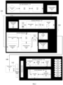
- FIG. 1 depicts a high-level diagram of an example of a neural stimulation system.
- the neural stimulation system may include four major components, namely, a programmer module 102, a RF pulse generator module 106, a transmit (TX) antenna 110 (for example, a patch antenna, slot antenna, or a dipole antenna), and an implanted wireless neural stimulator 114.
- the programmer module 102 may be a computer device, such as a smart phone, running a software application that supports a wireless connection 114, such as Bluetooth ® .
- the application can enable the user to view the system status and diagnostics, change various parameters, increase/decrease the desired stimulus amplitude of the electrode pulses, and adjust feedback sensitivity of the RF pulse generator module 106, among other functions.
- a closed loop feedback control method can be used in which the output signals from the implanted wireless neural stimulator module 114 are monitored and used to determine the appropriate level of neural stimulation current for maintaining effective neuronal activation, or, in some cases, the patient can manually adjust the output signals in an open loop control method.
- the implantable neural stimulator module 114 or RF pulse generator module 114 may be initially programmed to meet the specific parameter settings for each individual patient during the initial implantation procedure. Because medical conditions or the body itself can change over time, the ability to re-adjust the parameter settings may be beneficial to ensure ongoing efficacy of the neural modulation therapy.
- the RF pulse generator module 106 may be connected via wired connection 108 to an external TX antenna 110. Alternatively, both the antenna and the RF pulse generator are located subcutaneously (not shown).
- the signals sent by RF pulse generator module 106 to the implanted stimulator 114 may include both power and parameter-setting attributes in regards to stimulus waveform, amplitude, pulse width, and frequency.
- the RF pulse generator module 106 can also function as a wireless receiving unit that receives feedback signals from the implanted stimulator module 114.
- the RF pulse generator module 106 may contain microelectronics or other circuitry to handle the generation of the signals transmitted to the stimulator module 114 as well as handle feedback signals, such as those from the stimulator module 114.
- the RF pulse generator module 106 may comprise controller subsystem 214, high-frequency oscillator 218, RF amplifier 216, a RF switch, and a feedback subsystem 212.
- the controller subsystem 214 may include a CPU 230 to handle data processing, a memory subsystem 228 such as a local memory, communication subsystem 234 to communicate with programmer module 102 (including receiving stimulation parameters from programmer module), pulse generator circuitry 236, and digital/analog (D/A) converters 232.
- the clinician may have the option of locking and/or hiding certain settings within the programmer interface, thus limiting the patient's ability to view or adjust certain parameters because adjustment of certain parameters may require detailed medical knowledge of neurophysiology, neuroanatomy, protocols for neural modulation, and safety limits of electrical stimulation.
- the controller subsystem 214 may store received parameter settings in the local memory subsystem 228, until the parameter settings are modified by new input data received from the programming module 102.
- the CPU 206 may use the parameters stored in the local memory to control the pulse generator circuitry 236 to generate a stimulus waveform that is modulated by a high frequency oscillator 218 in the range from 300 MHz to 8 GHz.
- the resulting RF signal may then be amplified by RF amplifier 226 and then sent through an RF switch 223 to the TX antenna 110 to reach through depths of tissue to the RX antenna 238.
- the RF signal sent by TX antenna 110 may simply be a power transmission signal used by stimulator module 114 to generate electric pulses.
- a telemetry signal may also be transmitted to the stimulator module 114 to send instructions about the various operations of the stimulator module 114.
- the telemetry signal may be sent by the modulation of the carrier signal (through the skin if external, or through other body tissues if the pulse generator module 106 is implanted subcutaneously).
- the telemetry signal is used to modulate the carrier signal (a high frequency signal) that is coupled onto the implanted antenna(s) 238 and does not interfere with the input received on the same lead to power the implant.
- the telemetry signal and powering signal are combined into one signal, where the RF telemetry signal is used to modulate the RF powering signal, and thus the implanted stimulator is powered directly by the received telemetry signal; separate subsystems in the stimulator harness the power contained in the signal and interpret the data content of the signal.
- the RF switch 223 may be a multipurpose device such as a dual directional coupler, which passes the relatively high amplitude, extremely short duration RF pulse to the TX antenna 110 with minimal insertion loss while simultaneously providing two low-level outputs to feedback subsystem 212; one output delivers a forward power signal to the feedback subsystem 212, where the forward power signal is an attenuated version of the RF pulse sent to the TX antenna 110, and the other output delivers a reverse power signal to a different port of the feedback subsystem 212, where reverse power is an attenuated version of the reflected RF energy from the TX Antenna 110.
- a multipurpose device such as a dual directional coupler, which passes the relatively high amplitude, extremely short duration RF pulse to the TX antenna 110 with minimal insertion loss while simultaneously providing two low-level outputs to feedback subsystem 212; one output delivers a forward power signal to the feedback subsystem 212, where the forward power signal is an attenuated version of the RF pulse sent to the TX antenna
- the RF switch 223 is set to send the forward power signal to feedback subsystem.
- the RF switch 223 can change to a receiving mode in which the reflected RF energy and/or RF signals from the stimulator module 114 are received to be analyzed in the feedback subsystem 212.
- the feedback subsystem 212 of the RF pulse generator module 106 may include reception circuitry to receive and extract telemetry or other feedback signals from the stimulator 114 and/or reflected RF energy from the signal sent by TX antenna 110.
- the feedback subsystem may include an amplifier 226, a filter 224, a demodulator 222, and an A/D converter 220.
- the reverse power signal can be used to detect fault conditions in the RF-power delivery system.
- TX antenna 110 has perfectly matched impedance to the tissue that it contacts, the electromagnetic waves generated from the RF pulse generator 106 pass unimpeded from the TX antenna 110 into the body tissue.
- a large degree of variability may exist in the body types of users, types of clothing worn, and positioning of the antenna 110 relative to the body surface.
- the impedance of the antenna 110 depends on the relative permittivity of the underlying tissue and any intervening materials, and also depends on the overall separation distance of the antenna from the skin, in any given application there can be an impedance mismatch at the interface of the TX antenna 110 with the body surface. When such a mismatch occurs, the electromagnetic waves sent from the RF pulse generator 106 are partially reflected at this interface, and this reflected energy propagates backward through the antenna feed.
- the controller subsystem 214 can measure the reflected-power ratio in real time, and according to preset thresholds for this measurement, the controller subsystem 214 can modify the level of RF power generated by the RF pulse generator 106. For example, for a moderate degree of reflected power the course of action can be for the controller subsystem 214 to increase the amplitude of RF power sent to the TX antenna 110, as would be needed to compensate for slightly non-optimum but acceptable TX antenna coupling to the body. For higher ratios of reflected power, the course of action can be to prevent operation of the RF pulse generator 106 and set a fault code to indicate that the TX antenna 110 has little or no coupling with the body.
- This type of reflected-power fault condition can also be generated by a poor or broken connection to the TX antenna. In either case, it may be desirable to stop RF transmission when the reflected-power ratio is above a defined threshold, because internally reflected power can lead to unwanted heating of internal components, and this fault condition means the system cannot deliver sufficient power to the implanted wireless neural stimulator and thus cannot deliver therapy to the user.
- the controller 242 of the stimulator 114 may transmit informational signals, such as a telemetry signal, through the antenna 238 to communicate with the RF pulse generator module 106 during its receive cycle.
- the telemetry signal from the stimulator 114 may be coupled to the modulated signal on the dipole antenna(s) 238, during the on and off state of the transistor circuit to enable or disable a waveform that produces the corresponding RF bursts necessary to transmit to the external (or remotely implanted) pulse generator module 106.
- the antenna(s) 238 may be connected to electrodes 254 in contact with tissue to provide a return path for the transmitted signal.
- An A/D (not shown) converter can be used to transfer stored data to a serialized pattern that can be transmitted on the pulse modulated signal from the internal antenna(s) 238 of the neural stimulator.
- a telemetry signal from the implanted wireless neural stimulator module 114 may include stimulus parameters such as the power or the amplitude of the current that is delivered to the tissue from the electrodes.
- the feedback signal can be transmitted to the RF pulse generator module 116 to indicate the strength of the stimulus at the nerve bundle by means of coupling the signal to the implanted RX antenna 238, which radiates the telemetry signal to the external (or remotely implanted) RF pulse generator module 106.
- the feedback signal can include either or both an analog and digital telemetry pulse modulated carrier signal. Data such as stimulation pulse parameters and measured characteristics of stimulator performance can be stored in an internal memory device within the implanted neural stimulator 114, and sent on the telemetry signal.
- the frequency of the carrier signal may be in the range of at 300 MHz to 8 GHz.
- the current limiter 248 insures the current level of the pulses applied to the electrodes 254 is not above a threshold current level.
- an amplitude (for example, current level, voltage level, or power level) of the received RF pulse directly determines the amplitude of the stimulus.
- it is the charge per phase that should be limited for safety where the charge delivered by a stimulus phase is the integral of the current).
- the limiter 248 acts as a charge limiter that limits a characteristic (for example, current or duration) of the electrical pulses so that the charge per phase remains below a threshold level (typically, a safe-charge limit).
- the current limiter 248 can automatically limit or "clip" the stimulus phase to maintain the total charge of the phase within the safety limit.
- the current limiter 248 may be a passive current limiting component that cuts the signal to the electrodes 254 once the safe current limit (the threshold current level) is reached. Alternatively, or additionally, the current limiter 248 may communicate with the electrode interface 252 to turn off all electrodes 254 to prevent tissue damaging current levels.
- the repetition rate for the set-B stimulus cycle can be set independently of set A, say for example it could be specified at 25 cycles per second. Or, if the controller 250 was configured to match the repetition rate for set B to that of set A, for such a case the controller 250 can specify the relative start times of the stimulus cycles to be coincident in time or to be arbitrarily offset from one another by some delay interval.
- the controller 250 can arbitrarily shape the stimulus waveform amplitude, and may do so in response to instructions from pulse generator 106.
- the stimulus phase may be delivered by a constant-current source or a constant-voltage source, and this type of control may generate characteristic waveforms that are static, e.g. a constant-current source generates a characteristic rectangular pulse in which the current waveform has a very steep rise, a constant amplitude for the duration of the stimulus, and then a very steep return to baseline.
- the controller 250 can increase or decrease the level of current at any time during the stimulus phase and/or during the charge-balancing phase.
- the controller 250 can deliver arbitrarily shaped stimulus waveforms such as a triangular pulse, sinusoidal pulse, or Gaussian pulse for example.
- the charge-balancing phase can be arbitrarily amplitude-shaped, and similarly a leading anodic pulse (prior to the stimulus phase) may also be amplitude-shaped.
- the stimulator 114 may include a charge-balancing component 246.
- pulses should be charge balanced by having the amount of cathodic current should equal the amount of anodic current, which is typically called biphasic stimulation.
- Charge density is the amount of current times the duration it is applied, and is typically expressed in the units uC/cm 2 .
- no net charge should appear at the electrode-electrolyte interface, and it is generally acceptable to have a charge density less than 30 uC/cm 2 .
- Biphasic stimulating current pulses ensure that no net charge appears at the electrode after each stimulation cycle and the electrochemical processes are balanced to prevent net dc currents.
- Neural stimulator 114 may be designed to ensure that the resulting stimulus waveform has a net zero charge. Charge balanced stimuli are thought to have minimal damaging effects on tissue by reducing or eliminating electrochemical reaction products created at the electrode-tissue interface.
- a stimulus pulse may have a negative- voltage or current, called the cathodic phase of the waveform.
- Stimulating electrodes may have both cathodic and anodic phases at different times during the stimulus cycle.
- An electrode that delivers a negative current with sufficient amplitude to stimulate adjacent neural tissue is called a "stimulating electrode.”
- the stimulating electrode acts as a current sink.
- One or more additional electrodes act as a current source and these electrodes are called “return electrodes.” Return electrodes are placed elsewhere in the tissue at some distance from the stimulating electrodes.
- the return electrode When a typical negative stimulus phase is delivered to tissue at the stimulating electrode, the return electrode has a positive stimulus phase.
- the polarities of each electrode are reversed.
- the charge balance component 246 uses a blocking capacitor(s) placed electrically in series with the stimulating electrodes and body tissue, between the point of stimulus generation within the stimulator circuitry and the point of stimulus delivery to tissue.
- a resistor-capacitor (RC) network may be formed.
- one charge-balance capacitor(s) may be used for each electrode or a centralized capacitor(s) may be used within the stimulator circuitry prior to the point of electrode selection.
- the RC network can block direct current (DC), however it can also prevent low-frequency alternating current (AC) from passing to the tissue.
- the wireless neural stimulator module 114 may create a drive-waveform envelope that follows the envelope of the RF pulse received by the receiving dipole antenna(s) 238.
- the RF pulse generator module 106 can directly control the envelope of the drive waveform within the wireless neural stimulator 114, and thus no energy storage may be required inside the stimulator itself.
- the stimulator circuitry may modify the envelope of the drive waveform or may pass it directly to the charge-balance capacitor and/or electrode-selection stage.
- the implanted neural stimulator 114 may deliver a single-phase drive waveform to the charge balance capacitor or it may deliver multiphase drive waveforms.
- a single-phase drive waveform for example, a negative-going rectangular pulse
- this pulse comprises the physiological stimulus phase
- the charge-balance capacitor is polarized (charged) during this phase.
- the charge balancing function is performed solely by the passive discharge of the charge-balance capacitor, where is dissipates its charge through the tissue in an opposite polarity relative to the preceding stimulus.
- a resistor within the stimulator facilitates the discharge of the charge-balance capacitor.
- the capacitor may allow virtually complete discharge prior to the onset of the subsequent stimulus pulse.
- the amplitude and timing of stimulus and charge-balancing phases is controlled by the amplitude and timing of RF pulses from the RF pulse generator module 106, and in others this control may be administered internally by circuitry onboard the wireless stimulator 114, such as controller 250. In the case of onboard control, the amplitude and timing may be specified or modified by data commands delivered from the pulse generator module 106.
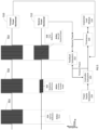
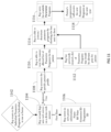
- the user may press the up arrow on the application screen, as shown in block 808.
- the application can include safety maximum limiting algorithms, so if a request to increase current amplitude is recognized by the application as exceeding the preset safety maximum, as shown in block 810, then the application will display an error message, as shown in block 812 and will not communicate with the RF pulse generator module 106. If the user presses the up arrow, as shown in block 808 and the current amplitude request does not exceed the current amplitude maximum allowable value, then the application will send instructions to the RF pulse generator module 106 to increase amplitude, as shown in block814.
- the user can press the down arrow on the application, as shown in block 828. If the current amplitude level is already at zero, the application recognizes that the current amplitude cannot be decreased any further, as shown in block 830 and displays an error message to the user without communicating any data to the RF pulse generator, as shown in block 832. If the current amplitude level is not at zero, the application can send instructions to the RF pulse generator module 106 to decrease current amplitude level accordingly, as shown in block 834.
- the RF pulse generator may then attempt to decrease current amplitude level of stimulation RF pulse generator module 106 and, if successful, the RF pulse generator module 106 may perform a short vibration to physically confirm to the user that the current amplitude level has been decreased, as shown in block 842.
- the RF pulse generator module 106 can send back confirmation of the decreased current amplitude level to the application, as shown in block 838.
- the application then may display the updated current amplitude level, as indicated by block 840. If the current amplitude level decrease or increase fails, the RF pulse generator module 106 can perform a series of short vibrations to alert user, and send an error message to the application, as shown in block 824.
- the application receives the error and may display the data for the user's benefit, as shown in block 826.
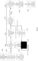
- the user can open the application on their smart device, as indicated by block 704, which first follows the process described in FIG 7 , communicating with the RF pulse generator module 106, authenticating successfully, and displaying the current status of the RF pulse generator module 106, including the current program parameter settings, as indicated by block 812.
- the user can select the program that they wish to use, as shown by block 904.
- the application may then access a library of pre-programmed parameters that have been approved by the Manufacturer's Representative for the user to interchange between as desired and in accordance with the management of their indication, as indicated by block 906.
- a table can be displayed to the user, as shown in block 908 and each row displays a program's codename and lists its basic parameter settings, as shown in block 910, which includes but is not limited to: pulse width, frequency, cycle timing, pulse shape, duration, feedback sensitivity, as shown in block 912.
- the user may then select the row containing the desired parameter preset program to be used, as shown in block 912.
- the application can send instructions to the RF pulse generator module 106 to change the parameter settings, as shown in block 916.
- the RF pulse generator module 106 may attempt to change the parameter settings 154. If the parameter settings are successfully changed, the RF pulse generator module 106 can perform a unique vibration pattern to physically confirm with the user that the parameter settings were changed, as shown in block 920.
- the RF pulse generator module 106 may always perform one sequence of short vibrations to alert the user of an issue and send the application a notification, as shown in block 1010. If there continues to be no confirmation of the application receiving the notification then the RF pulse generator can continue to perform short vibration pulses to notify user, as shown in block 1010. If the application successfully receives the notification, it may display the notification and may need user acknowledgement, as shown in block 1012. If, for example, one minute passes without the notification message on the application being dismissed the application informs the RF pulse generator module 106 about lack of human acknowledgement, as shown in block 1014, and the RF pulse generator module 106 may begin to perform the vibration pulses to notify the user, as shown in block 1010.
- the RF pulse generator module 106 may push a successful battery-change notification to the application, as shown in block 1020.
- the application may then communicate with the RF pulse generator module 106 and displays current system status, as shown in block 1022.
- the Manufacturer's Representative accesses the specific user's profile, as shown in block 1108.
- the Manufacturer's Representative is able to view the current allotted list of parameter programs for the specific user, as shown in block 1110. This list may contain previous active and retired parameter preset programs, as shown in block 1112.
- the Manufacturer's Representative is able to activate/deactivate preset parameter programs by checking the box next to the appropriate row in the table displayed, as shown in block 1114.
- the Manufacturer's Representative may then submit and save the allotted new preset parameter programs, as shown in block 1116.
- the user's programmer application may receive the new preset parameter programs at the next sync with the manufacturer's database.
- the natural inefficiency of the lossy material may lead to a low threshold voltage.
- a zero biased diode rectifier results in a low output impedance for the device.
- a resistor 1204 and a smoothing capacitor 1206 are placed across the output nodes of the bridge rectifier to discharge the electrodes to the ground of the bridge anode.
- the rectification bridge 1202 includes two branches of diode pairs connecting an anode-to-anode and then cathode to cathode.
- the electrodes 1208 and 1210 are connected to the output of the charge balancing circuit 246.
- FIG. 13 is a circuit diagram of another example of a wireless neural stimulator, such as stimulator 114.
- the example shown in FIG. 13 includes multiple electrode control and may employ full closed loop control.
- the stimulator includes an electrode array 254 in which the polarity of the electrodes can be assigned as cathodic or anodic, and for which the electrodes can be alternatively not powered with any energy. When energized, the charged electrodes create a volume conduction field of current density within the tissue.
- the wireless energy is received by the device through the dipole antenna(s) 238.
- the electrode array 254 is controlled through an on-board controller circuit 242 that sends the appropriate bit information to the electrode interface 252 in order to set the polarity of each electrode in the array, as well as power to each individual electrode.
- the lack of power to a specific electrode would set that electrode in a functional OFF position.
- the amount of current sent to each electrode is also controlled through the controller 242.
- the controller current, polarity and power state parameter data shown as the controller output, is be sent back to the antenna(s) 238 for telemetry transmission back to the pulse generator module 106.
- the controller 242 also includes the functionality of current monitoring and sets a bit register counter so that the status of total current drawn can be sent back to the pulse generator module 106.
- At least four diodes can be connected together to form a full wave bridge rectifier 302 attached to the dipole antenna(s) 238.
- Each diode up to 100 micrometers in length, uses a junction potential to prevent the flow of negative electrical current, from cathode to anode, from passing through the device when said current does not exceed the reverse threshold.
- the natural inefficiency of the lossy material may lead to a low threshold voltage.
- a zero biased diode rectifier results in a low output impedance for the device.
- a resistor 1204 and a smoothing capacitor 1206 are placed across the output nodes of the bridge rectifier to discharge the electrodes to the ground of the bridge anode.
- the rectification bridge 1202 may include two branches of diode pairs connecting an anode-to-anode and then cathode to cathode.
- the electrode polarity outputs, both cathode 1208 and anode 1210 are connected to the outputs formed by the bridge connection.
- Charge balancing circuitry 246 and current limiting circuitry 248 are placed in series with the outputs.
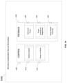
- FIG. 14 is a block diagram showing an example of control functions 1405 and feedback functions 1430 of a wireless implantable neural stimulator 1400, such as the ones described above or further below.
- An example implementation of the implantable neural stimulator 1400 may be implanted lead module 114, as discussed above in association with FIG. 2 .
- Control functions 1405 include functions 1410 for polarity switching of the electrodes and functions 1420 for power-on reset.
- Polarity switching functions 1410 may employ, for example, a polarity routing switch network to assign polarities to electrodes 254.
- the assignment of polarity to an electrode may, for instance, be one of: a cathode (negative polarity), an anode (positive polarity), or a neutral (off) polarity.
- the polarity assignment information for each of the electrodes 254 may be contained in the input signal received by wireless implantable neural stimulator 1400 through Rx antenna 238 from RF pulse generator module 106. Because a programmer module 102 may control RF pulse generator module 106, the polarity of electrodes 254 may be controlled remotely by a programmer through programmer module 102, as shown in Fig. 2 .
- Power-on reset functions 1420 may reset the polarity assignment of each electrode immediately on each power-on event. As will be described in further detail below, this reset operation may cause RF pulse generator module 106 to transmit the polarity assignment information to the wireless implantable neural stimulator 1400. Once the polarity assignment information is received by the wireless implantable neural stimulator 1400, the polarity assignment information may be stored in a register file, or other short term memory component. Thereafter the polarity assignment information may be used to configure the polarity assignment of each electrode. If the polarity assignment information transmitted in response to the reset encodes the same polarity state as before the power-on event, then the polarity state of each electrode can be maintained before and after each power-on event.
- Feedback functions 1430 may additionally include tissue depth estimate functions 1460 to provide data indicating the overall tissue depth that the input radio frequency (RF) signal from the pulse generator module, such as, for example, RF pulse generator module 106, has penetrated before reaching the implanted antenna, such as, for example, RX antenna 238, within the wireless implantable neural stimulator 1400, such as, for example, implanted lead module 114.
- the tissue depth estimate may be provided by comparing the power of the received input signal to the power of the RF pulse transmitted by the RF pulse generator 106. The ratio of the power of the received input signal to the power of the RF pulse transmitted by the RF pulse generator 106 may indicate an attenuation caused by wave propagation through the tissue.
- the second harmonic described below may be received by the RF pulse generator 106 and used with the power of the input signal sent by the RF pulse generator to determine the tissue depth.
- the attenuation may be used to infer the overall depth of wireless implantable neural stimulator 1400 underneath the skin.
- a wireless implantable neural stimulator 1400 may utilize rectification circuitry to convert the input signal (e.g., having a carrier frequency within a range from about 800 MHz to about 6 GHz) to a direct current (DC) power to drive the electrodes 254.
- Some implementations may provide the capability to regulate the DC power remotely.
- Some implementations may further provide different amounts of power to different electrodes, as discussed in further detail below.
- power and impedance sensing circuitry may be used to determine the power delivered to the tissue and the impedance of the tissue.
- a sensing resistor 1518 may be placed in serial connection with the anodic branch 1514.
- Current sensing circuit 1519 senses the current across the resistor 1518 and voltage sensing circuit 1520 senses the voltage across the resistor. The measured current and voltage may correspond to the actual current and voltage applied by the electrodes to the tissue.
- the bits may encode the polarity assignment for each output of the polarity routing switch network as one of: + (positive), - (negative), or 0 (neutral). Each output connects to one electrode and the channel setting determines whether the electrode will be set as an anode (positive), cathode (negative), or off (neutral).
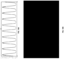
- FIG. 18A and 18BB respectively show an example full-wave rectified sine wave and the corresponding spectrum.
- a full-wave rectified 915 MHz sine wave is being analyzed.
- the second harmonic of the 915 MHz sine wave is an 1830 MHz output harmonic.
- This harmonic wave may be attenuated by the amount of tissue that the harmonic wave needs to pass through before reaching the external harmonic receiver antenna.
- an estimation of the power levels during the propagation of the harmonic wave can reveal the feasibility of the approach.
- the estimation may consider the power of received input signal at the receiving antenna (e.g., at antenna 1505 and at 915 MHz), the power of the second harmonic radiated from the rectified 915MHz waveform, the amount of attenuation for the second harmonic wave to propagate through the tissue medium, and an estimation of the coupling efficiency for the harmonic antenna.
- the worst case assumption for coupling of the harmonics wave to the external receive antenna is that the power radiated at the harmonic frequency by the implanted telemetry antenna (e.g., telemetry antenna 1625) is completely absorbed by external receive antenna.
- the reduction of power levels has been estimated to be about 10 dB utilizing these developed equations.
- the average received power, Pr, at 915 MHz is 0.356 W.
- the power in the second harmonic (1830 MHz) is about -6.16 dB, as obtained from a SPICE simulation using a full wave rectified 915 MHz sine wave.
- the estimate of 10dB means a reduction of a factor of 10, which is acceptable for field operations.
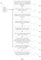
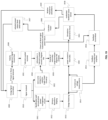
- FIG. 19 is a flow chart illustrating an example of operations of control and feedback functions of the neural stimulator. The operations are described with respect to the wireless implantable neural stimulator 1500, although the operations may be performed by other variations of a wireless implantable neural stimulator, such as the ones described above.
- RF pulse generator module 106 transmits one or more signals containing electrical energy (1900).
- RF pulse generator module 106 may also be known as a microwave field stimulator (MFS) in some implementations.
- the signal may be modulated at a microwave frequency band, for example, from about 800 MHz to about 6GHz.
- RX antenna 1505 of the neural stimulator 1500 (1910) The input signal containing electrical energy is received by RX antenna 1505 of the neural stimulator 1500 (1910).
- RX antenna 1505 may be embedded as a dipole, microstrip, folded dipole or other antenna configuration other than a coiled configuration.
- the input signal is rectified and demodulated by the power management circuitry 1510, as shown by block 1911.
- Some implementations may provide waveform shaping and, in this case, the rectified and demodulated signal is passed to pulse shaping RC timer (1912).
- Charge balancing may be performed by charge balancing circuit 1518 to provide a charged balanced waveform (1913). Thereafter, the shaped and charge balanced pulses are routed to electrodes 254 (1920), which deliver the stimulation to the excitable tissue (1921).
- the current and voltage being delivered to the tissue is measured using the current sensor 1519 and voltage sensor 1520 (1914). These measurements are modulated and amplified (1915) and transmitted to the RF pulse generator module 106 from telemetry antenna 1525 (1916).
- the telemetry antenna 1525 and RX antenna 1505 may utilize the same physical antenna embedded within the neural stimulator 1500.
- the RF pulse generator module 106 may use the measured current and voltage to determine the power delivered to the tissue, as well as the impedance of the tissue.
- the RF pulse generator module 106 may store the received feedback information such as the information encoding the current and voltage.
- the feedback information may be stored, for instance, as a present value in a hardware memory on RF pulse generator module 106.
- RF pulse generator module 106 may calculate the impedance value of the tissue based on the current and voltage delivered to the tissue.
- RF pulse generator module 106 may calculate the power delivered to the tissue based on the stored current and voltage (1950). The RF pulse generator module 106 can then determine whether power level should be adjusted by comparing the calculated power to the desired power stored, for example, in a lookup table stored on the RF pulse generator module 106 (1917). For example, the look-up table may tabulate the optimal amount of power that should be delivered to the tissue for the position of the receive antenna 1505 on neural stimulator 1500 relative to the position of the transmit antenna on RF pulse generator module 106. This relative position may be determined based on the feedback information.
- the power measurements in the feedback information may then be correlated to the optimal value to determine if a power level adjustment should be made to increase or decrease the amplitude of stimulation of the delivered power to the electrodes.
- the power level adjustment information may then enable the RF pulse generator module 106 to adjust parameters of transmission so that the adjusted power is provided to the RX antenna 1505.
- the RF pulse generator module 106 may send an input signal that contains telemetry data such as polarity assignment information (1930). For instance, upon power on, the RF pulse generator module 106 may transmit data encoding the last electrode polarity settings for each electrode before RF pulse generator module 106 was powered off. This data may be sent to telemetry antenna 1525 as a digital data stream embedded on the carrier waveform. In some implementations, the data stream may include telemetry packets. The telemetry packets are received from the RF pulse generator module 106 and subsequently demodulated (1931) by demodulation circuit 1531. The polarity setting information in the telemetry packets is stored in the register file 1532 (1932).
- the polarity of each electrode of electrodes 254 is programmed according to the polarity setting information stored in the register file 1532 (1933).
- the polarity of each electrode may be set as one of: anode (positive), cathode (negative), or neutral (off).
- the polarity setting information is resent from the RF pulse generator module 106 to be stored in the register file 1532 (1932). This is indicated by the arrow 1932 to 1916.
- the information of polarity setting stored in the register file 1532 may then be used to program the polarity of each electrode of electrodes 254 (1933).
- the feature allows for re-programming of a passive device remotely from the RF pulse generator module 106 at the start of each powered session, thus obviating the need of maintaining CMOS memory within the neural stimulator 1500.
Landscapes
- Health & Medical Sciences (AREA)
- Public Health (AREA)
- General Health & Medical Sciences (AREA)
- Nuclear Medicine, Radiotherapy & Molecular Imaging (AREA)
- Radiology & Medical Imaging (AREA)
- Life Sciences & Earth Sciences (AREA)
- Animal Behavior & Ethology (AREA)
- Biomedical Technology (AREA)
- Veterinary Medicine (AREA)
- Engineering & Computer Science (AREA)
- Physics & Mathematics (AREA)
- Neurology (AREA)
- Electromagnetism (AREA)
- Acoustics & Sound (AREA)
- Neurosurgery (AREA)
- Heart & Thoracic Surgery (AREA)
- Electrotherapy Devices (AREA)
Applications Claiming Priority (7)
| Application Number | Priority Date | Filing Date | Title |
|---|---|---|---|
| US201161513397P | 2011-07-29 | 2011-07-29 | |
| PCT/US2012/023029 WO2012103519A2 (en) | 2011-01-28 | 2012-01-27 | Neural stimulator system |
| PCT/US2012/048903 WO2013019757A2 (en) | 2011-07-29 | 2012-07-30 | Remote control of power or polarity selection for a neural stimulator |
| EP12819482.6A EP2736592B1 (de) | 2011-07-29 | 2012-07-30 | Fernsteuerung von leistungs- oder polaritätsauswahl für einen nervenstimulator |
| EP23206731.4A EP4356954B1 (de) | 2011-07-29 | 2012-07-30 | Fernsteuerung der leistungs- oder polaritätsauswahl für einen nervenstimulator |
| EP20168726.6A EP3747507B1 (de) | 2011-07-29 | 2012-07-30 | Fernsteuerung der leistungs- oder polaritätsauswahl für einen nervenstimulator |
| EP18150779.9A EP3338855B1 (de) | 2011-07-29 | 2012-07-30 | Fernsteuerung von leistungs- oder polaritätsauswahl für einen nervenstimulator |
Related Parent Applications (4)
| Application Number | Title | Priority Date | Filing Date |
|---|---|---|---|
| EP20168726.6A Division EP3747507B1 (de) | 2011-07-29 | 2012-07-30 | Fernsteuerung der leistungs- oder polaritätsauswahl für einen nervenstimulator |
| EP23206731.4A Division EP4356954B1 (de) | 2011-07-29 | 2012-07-30 | Fernsteuerung der leistungs- oder polaritätsauswahl für einen nervenstimulator |
| EP18150779.9A Division EP3338855B1 (de) | 2011-07-29 | 2012-07-30 | Fernsteuerung von leistungs- oder polaritätsauswahl für einen nervenstimulator |
| EP12819482.6A Division EP2736592B1 (de) | 2011-07-29 | 2012-07-30 | Fernsteuerung von leistungs- oder polaritätsauswahl für einen nervenstimulator |
Publications (2)
| Publication Number | Publication Date |
|---|---|
| EP4537891A2 true EP4537891A2 (de) | 2025-04-16 |
| EP4537891A3 EP4537891A3 (de) | 2025-05-14 |
Family
ID=47629880
Family Applications (5)
| Application Number | Title | Priority Date | Filing Date |
|---|---|---|---|
| EP12819482.6A Active EP2736592B1 (de) | 2011-07-29 | 2012-07-30 | Fernsteuerung von leistungs- oder polaritätsauswahl für einen nervenstimulator |
| EP20168726.6A Active EP3747507B1 (de) | 2011-07-29 | 2012-07-30 | Fernsteuerung der leistungs- oder polaritätsauswahl für einen nervenstimulator |
| EP23206731.4A Active EP4356954B1 (de) | 2011-07-29 | 2012-07-30 | Fernsteuerung der leistungs- oder polaritätsauswahl für einen nervenstimulator |
| EP18150779.9A Active EP3338855B1 (de) | 2011-07-29 | 2012-07-30 | Fernsteuerung von leistungs- oder polaritätsauswahl für einen nervenstimulator |
| EP24218384.6A Pending EP4537891A3 (de) | 2011-07-29 | 2012-07-30 | Fernsteuerung der leistungs- oder polaritätsauswahl für einen nervenstimulator |
Family Applications Before (4)
| Application Number | Title | Priority Date | Filing Date |
|---|---|---|---|
| EP12819482.6A Active EP2736592B1 (de) | 2011-07-29 | 2012-07-30 | Fernsteuerung von leistungs- oder polaritätsauswahl für einen nervenstimulator |
| EP20168726.6A Active EP3747507B1 (de) | 2011-07-29 | 2012-07-30 | Fernsteuerung der leistungs- oder polaritätsauswahl für einen nervenstimulator |
| EP23206731.4A Active EP4356954B1 (de) | 2011-07-29 | 2012-07-30 | Fernsteuerung der leistungs- oder polaritätsauswahl für einen nervenstimulator |
| EP18150779.9A Active EP3338855B1 (de) | 2011-07-29 | 2012-07-30 | Fernsteuerung von leistungs- oder polaritätsauswahl für einen nervenstimulator |
Country Status (6)
| Country | Link |
|---|---|
| US (4) | US9199089B2 (de) |
| EP (5) | EP2736592B1 (de) |
| JP (1) | JP2014524279A (de) |
| CN (2) | CN104080509B (de) |
| ES (1) | ES3010635T3 (de) |
| WO (1) | WO2013019757A2 (de) |
Families Citing this family (122)
| Publication number | Priority date | Publication date | Assignee | Title |
|---|---|---|---|---|
| US20120277839A1 (en) | 2004-09-08 | 2012-11-01 | Kramer Jeffery M | Selective stimulation to modulate the sympathetic nervous system |
| US9205261B2 (en) | 2004-09-08 | 2015-12-08 | The Board Of Trustees Of The Leland Stanford Junior University | Neurostimulation methods and systems |
| EP1880298B1 (de) | 2005-02-17 | 2016-07-13 | Metacure Limited | Ladegerät mit datentransferfähigkeiten |
| US9008781B2 (en) | 2009-10-22 | 2015-04-14 | The Research Foundation Of The City University Of New York | Method and system for treatment of mobility dysfunction |
| WO2011143233A2 (en) | 2010-05-10 | 2011-11-17 | Spinal Modulation, Inc. | Methods, systems and devices for reducing migration |
| US12115374B2 (en) | 2011-01-28 | 2024-10-15 | Curonix Llc | Microwave field stimulator |
| ES2988349T3 (es) | 2011-01-28 | 2024-11-20 | Curonix Llc | Sistema de estimulador neural |
| EP3586908B1 (de) | 2011-04-04 | 2024-11-13 | Curonix LLC | Implantierbarer neurostimulator mit drahtloser schnittstelle |
| KR101809466B1 (ko) * | 2011-05-27 | 2017-12-18 | 삼성전자주식회사 | 고효율 가변전력 송수신 장치 및 방법 |
| EP2736592B1 (de) | 2011-07-29 | 2018-01-10 | Micron Devices LLC | Fernsteuerung von leistungs- oder polaritätsauswahl für einen nervenstimulator |
| EP2741810B1 (de) | 2011-08-12 | 2021-03-31 | Stimwave Technologies Incorporated | Mikrowellenfeldstimulator |
| EP2755718B8 (de) | 2011-09-15 | 2018-06-06 | Micron Devices LLC | Relaismodul für ein implantat |
| US9764133B2 (en) * | 2012-01-13 | 2017-09-19 | Modular Therapeutx, Llc | Portable TENS apparatus and method of use thereof |
| US8994409B2 (en) * | 2012-05-22 | 2015-03-31 | Agency For Science, Technology And Research | Stimulator and method for processing a stimulation signal |
| US10463858B2 (en) | 2012-07-17 | 2019-11-05 | Stimwave Technologies Incorporated | Devices and methods for treating craniofacial pain |
| WO2014153218A1 (en) | 2013-03-14 | 2014-09-25 | Tyler Perryman Laura | Devices and methods for treating craniofacial pain |
| CN103777797B (zh) * | 2012-10-23 | 2017-06-27 | 联想(北京)有限公司 | 一种信息处理的方法及电子设备 |
| EP2914169B1 (de) * | 2012-10-31 | 2021-12-01 | The Board of Trustees of the Leland Stanford Junior University | Drahtlose implantierbare erfassungsvorrichtungen |
| BR112015013077B1 (pt) * | 2012-12-05 | 2022-02-08 | Micron Devices Llc | Dispositivo para fornecer uma sonda implantável com energia sem fio e sistema e método para modular tecido excitável em um corpo de um paciente |
| WO2014089405A1 (en) | 2012-12-07 | 2014-06-12 | Medtronic, Inc. | Minimally invasive implantable neurostimulation system |
| EP2938393A1 (de) | 2012-12-26 | 2015-11-04 | Micron Devices, LLC | Tragbare antennenanordnung |
| AU2014226176B2 (en) | 2013-03-07 | 2017-05-11 | Imthera Medical, Inc. | Lead splitter for neurostimulation systems |
| KR20160025490A (ko) * | 2013-03-07 | 2016-03-08 | 리서치 파운데이션 오브 더 시티 유니버시티 오브 뉴욕 | 신경 운동 기능 장애를 치료하기 위한 방법 및 시스템 |
| US10994149B2 (en) * | 2013-03-14 | 2021-05-04 | Stimwave Technologies Incorporated | Wireless implantable power receiver system and methods |
| US10098585B2 (en) | 2013-03-15 | 2018-10-16 | Cadwell Laboratories, Inc. | Neuromonitoring systems and methods |
| US20160121115A1 (en) * | 2013-05-15 | 2016-05-05 | Ripple Llc | Systems and methods for electrical stimulation of neural tissue |
| US11229789B2 (en) | 2013-05-30 | 2022-01-25 | Neurostim Oab, Inc. | Neuro activator with controller |
| EP3441109A1 (de) | 2013-05-30 | 2019-02-13 | Graham H. Creasey | Flexibles hautpflaster für ein stimulatorsystem für topische nerven |
| WO2014205407A2 (en) * | 2013-06-22 | 2014-12-24 | Micron Devices Llc | Methods and devices for the selective modulation of excitable tissue |
| US8831747B1 (en) | 2013-11-19 | 2014-09-09 | Pacesetter, Inc. | Leadless neurostimulation device and method including the same |
| US10004913B2 (en) | 2014-03-03 | 2018-06-26 | The Board Of Trustees Of The Leland Stanford Junior University | Methods and apparatus for power conversion and data transmission in implantable sensors, stimulators, and actuators |
| US10434329B2 (en) | 2014-05-09 | 2019-10-08 | The Board Of Trustees Of The Leland Stanford Junior University | Autofocus wireless power transfer to implantable devices in freely moving animals |
| AU2015259305B2 (en) | 2014-05-12 | 2019-09-12 | Curonix Llc | Remote RF power system with low profile transmitting antenna |
| US10265530B1 (en) | 2014-05-29 | 2019-04-23 | Stimwave Technologies Incorporated | Simulation with electrode arrays |
| EP3157620B1 (de) | 2014-06-21 | 2020-04-15 | Nalu Medical, Inc. | Vorrichtung für neuromodulationsbehandlungen von schmerzen und anderen störungen |
| CN106794340A (zh) * | 2014-07-10 | 2017-05-31 | 米克伦设备有限责任公司 | 用于可植入装置的电路 |
| US9572991B2 (en) * | 2014-08-07 | 2017-02-21 | Cardiac Pacemakers, Inc. | Medical device systems and methods with multiple communication modes |
| US9918669B2 (en) | 2014-08-08 | 2018-03-20 | Medtronic Xomed, Inc. | Wireless nerve integrity monitoring systems and devices |
| US12582344B2 (en) | 2014-08-08 | 2026-03-24 | Medtronic Xomed, Inc. | Wireless stimulation probe device for wireless nerve integrity monitoring systems |
| US12201436B2 (en) | 2014-08-08 | 2025-01-21 | Medtronic Xomed, Inc. | Wireless nerve integrity monitoring systems and devices |
| CN106470733A (zh) * | 2014-10-15 | 2017-03-01 | 株式会社色彩七 | 利用移动通信装置的基于平滑肌光活化调制技术的皮肤粘合型低功率光线照射器系统 |
| US10369365B2 (en) | 2014-11-26 | 2019-08-06 | Stimwave Technologies Incorporated | Controller interface for an implantable stimulator device |
| EP3242714B1 (de) | 2014-12-31 | 2021-06-02 | Stimwave Technologies Incorporated | Antennenanordnung |
| WO2016109833A1 (en) | 2014-12-31 | 2016-07-07 | Chad David Andresen | Patch antenna assembly |
| JP6452833B2 (ja) * | 2015-02-04 | 2019-01-16 | ボストン サイエンティフィック ニューロモデュレイション コーポレイション | 神経刺激波形内の電荷回復をプログラムするための方法及び装置 |
| US11077301B2 (en) | 2015-02-21 | 2021-08-03 | NeurostimOAB, Inc. | Topical nerve stimulator and sensor for bladder control |
| US10149976B1 (en) | 2015-03-06 | 2018-12-11 | Micron Devices Llc | Placement of neural stimulators |
| US10092755B1 (en) | 2015-03-09 | 2018-10-09 | Micro Devices Llc | Neural stimulator placement |
| US10272239B1 (en) | 2015-03-10 | 2019-04-30 | Stimwave Technologies Incorporated | Neural stimulator placement |
| US11980465B2 (en) | 2015-04-03 | 2024-05-14 | Medtronic Xomed, Inc. | System and method for omni-directional bipolar stimulation of nerve tissue of a patient via a bipolar stimulation probe |
| US10039915B2 (en) | 2015-04-03 | 2018-08-07 | Medtronic Xomed, Inc. | System and method for omni-directional bipolar stimulation of nerve tissue of a patient via a surgical tool |
| AU2016249420A1 (en) * | 2015-04-17 | 2017-11-09 | Micron Devices Llc | Flexible circuit for an implantable device |
| CN105310680B (zh) * | 2015-05-14 | 2018-03-27 | 南京神桥医疗器械有限公司 | 一种植入式神经信号阻断装置 |
| WO2016205398A1 (en) * | 2015-06-15 | 2016-12-22 | The Regents Of The University Of California | Radio frequency powered adiabatic stimulation with energy replenishment |
| US9867994B2 (en) | 2015-06-19 | 2018-01-16 | Boston Scientific Neuromodulation Corporation | External powering of implantable medical device dependent on energy of provided therapy |
| US10737098B2 (en) | 2015-06-22 | 2020-08-11 | Stimwave Technologies Incorporated | Earpiece assembly to interact with implantable neural stimulators |
| US10188866B2 (en) | 2015-06-24 | 2019-01-29 | Impulse Dynamics Nv | Simple control of complex bio-implants |
| EP3347085B1 (de) | 2015-09-11 | 2023-07-26 | Nalu Medical, Inc. | Vorrichtung für periphere oder spinale stimulation |
| US10445466B2 (en) | 2015-11-18 | 2019-10-15 | Warsaw Orthopedic, Inc. | Systems and methods for post-operative outcome monitoring |
| US10339273B2 (en) | 2015-11-18 | 2019-07-02 | Warsaw Orthopedic, Inc. | Systems and methods for pre-operative procedure determination and outcome predicting |
| US10576292B2 (en) | 2015-11-29 | 2020-03-03 | Boston Scientific Neuromodulation Corporation | Skull-mounted deep brain stimulator |
| US10420950B2 (en) | 2015-11-29 | 2019-09-24 | Boston Scientific Neuromodulation Corporation | Implantable pulse generator usable during a trial stimulation phase and externally powered by magnetic inductive coupling |
| WO2017124082A1 (en) | 2016-01-15 | 2017-07-20 | Richard Lebaron | An implantable relay module |
| CN106983954A (zh) * | 2016-01-20 | 2017-07-28 | 上海力声特医学科技有限公司 | 骶神经刺激器 |
| WO2017142948A1 (en) | 2016-02-19 | 2017-08-24 | Nalu Medical, Inc. | Apparatus with enhanced stimulation waveforms |
| WO2017141257A1 (en) * | 2016-02-21 | 2017-08-24 | Tech Innosphere Engineering Ltd. | Noninvasive electric brain stimulation system |
| WO2017165410A1 (en) | 2016-03-21 | 2017-09-28 | Nalu Medical, Inc. | Devices and methods for positioning external devices in relation to implanted devices |
| US10646164B1 (en) | 2016-05-24 | 2020-05-12 | Stimwave Technologies Incorporated | Pulse-density modulation to synthesize stimulation waveforms on an implantable device |
| US10632314B1 (en) | 2016-06-10 | 2020-04-28 | Stimwave Technologies Incorporated | User interface for a patient user to adjust settings on an implantable device |
| PT3481284T (pt) | 2016-07-07 | 2021-10-14 | Univ California | Implantes utilizando retrodifusão ultrassónica para detetar sinais eletrofisiológicos |
| EP3269424B1 (de) * | 2016-07-15 | 2021-12-01 | ONWARD Medical B.V. | Impulserzeugungssystem |
| WO2018017463A1 (en) | 2016-07-18 | 2018-01-25 | Nalu Medical, Inc. | Methods and systems for treating pelvic disorders and pain conditions |
| WO2018023057A1 (en) | 2016-07-28 | 2018-02-01 | Richard Lebaron | Fabric antenna |
| US9901735B1 (en) * | 2016-08-04 | 2018-02-27 | Y-Brain Inc | Ancillary device for electrical stimulation device and electrical stimulation device |
| US10849517B2 (en) | 2016-09-19 | 2020-12-01 | Medtronic Xomed, Inc. | Remote control module for instruments |
| US10735838B2 (en) * | 2016-11-14 | 2020-08-04 | Corning Optical Communications LLC | Transparent wireless bridges for optical fiber-wireless networks and related methods and systems |
| WO2018126062A1 (en) | 2016-12-30 | 2018-07-05 | Nalu Medical, Inc. | Stimulation apparatus |
| US9935395B1 (en) | 2017-01-23 | 2018-04-03 | Cadwell Laboratories, Inc. | Mass connection plate for electrical connectors |
| EP4417248A3 (de) | 2017-02-24 | 2024-10-23 | Nalu Medical, Inc. | Gerät mit sequenziell implantierten stimulatoren |
| CN117713996A (zh) * | 2017-03-24 | 2024-03-15 | 华为技术有限公司 | 极化码的速率匹配方法及设备 |
| WO2018208992A1 (en) | 2017-05-09 | 2018-11-15 | Nalu Medical, Inc. | Stimulation apparatus |
| US20180333578A1 (en) * | 2017-05-17 | 2018-11-22 | Nuvectra Corporation | System, device, and method for performing long duration pulse width stimulation without uncomfortable rib stimulation |
| EP3706856A4 (de) | 2017-11-07 | 2021-08-18 | Neurostim Oab, Inc. | Nicht-invasiver nervenaktivator mit adaptiver schaltung |
| US11331500B1 (en) | 2017-11-20 | 2022-05-17 | Stimwave Technologies Incorporated | Systems and methods to locate an implantable stimulator device inside a subject |
| AU2019215179B2 (en) | 2018-02-01 | 2024-11-07 | Curonix Llc | Systems and methods to sense stimulation electrode tissue impedance |
| AU2019255373B2 (en) | 2018-04-19 | 2025-02-06 | Iota Biosciences, Inc. | Implants using ultrasonic communication for modulating splenic nerve activity |
| US11033746B2 (en) | 2018-04-19 | 2021-06-15 | Iota Biosciences, Inc. | Implants using ultrasonic communication for neural sensing and stimulation |
| US11253182B2 (en) | 2018-05-04 | 2022-02-22 | Cadwell Laboratories, Inc. | Apparatus and method for polyphasic multi-output constant-current and constant-voltage neurophysiological stimulation |
| US11992339B2 (en) | 2018-05-04 | 2024-05-28 | Cadwell Laboratories, Inc. | Systems and methods for dynamic neurophysiological stimulation |
| US11266841B1 (en) | 2018-06-01 | 2022-03-08 | Stimwave Technologies Incorporated | Securing antennas to wearable articles |
| US11443649B2 (en) | 2018-06-29 | 2022-09-13 | Cadwell Laboratories, Inc. | Neurophysiological monitoring training simulator |
| US10872688B2 (en) * | 2018-07-30 | 2020-12-22 | Arxium, Inc. | Visual analysis pill dispenser |
| PL3843830T3 (pl) * | 2018-08-29 | 2024-08-12 | Iota Biosciences, Inc. | Wszczepialne urządzenie do neuromodulacji w zamkniętej pętli |
| US11439832B2 (en) | 2019-01-09 | 2022-09-13 | Stimwave Technologies Incorporated | Implantable electronic devices |
| US11672990B2 (en) | 2019-01-15 | 2023-06-13 | Stimwave Technologies Incorporated | Headsets for positioning electronic devices |
| US10946199B2 (en) * | 2019-05-02 | 2021-03-16 | Advanced Neuromodulation Systems, Inc. | Neurostimulation method and system for active emulation of passive discharge in presence of MRI/EMI interference |
| US11458311B2 (en) | 2019-06-26 | 2022-10-04 | Neurostim Technologies Llc | Non-invasive nerve activator patch with adaptive circuit |
| AU2020298574B2 (en) | 2019-07-02 | 2025-11-27 | Nalu Medical, Inc. | Stimulation apparatus |
| US11065461B2 (en) | 2019-07-08 | 2021-07-20 | Bioness Inc. | Implantable power adapter |
| AU2020311913B2 (en) * | 2019-07-08 | 2026-01-22 | Bioness Inc. | Apparatus and methods for providing electric energy to a subject |
| CN110327547B (zh) * | 2019-07-17 | 2024-05-10 | 杭州承诺医疗科技有限公司 | 一种多通道多刺激源的脑深部电刺激系统 |
| CN114175743B (zh) * | 2019-08-16 | 2024-06-25 | 华为技术有限公司 | 一种用于信号发送的方法、装置以及用于信号接收的方法、装置 |
| WO2021067873A1 (en) | 2019-10-04 | 2021-04-08 | Nalu Medical, Inc. | Stimulation apparatus |
| KR20220082063A (ko) | 2019-10-17 | 2022-06-16 | 아이오타 바이오사이언시즈 인코퍼레이티드 | 암 환자에서 면역 시스템 활동을 조정하고 암을 치료하기 위한 장치 및 방법 |
| WO2021097342A1 (en) | 2019-11-13 | 2021-05-20 | Stimwave Technologies Incorporated | Manufacturing implantable tissue stimulators |
| EP4017580A4 (de) | 2019-12-16 | 2023-09-06 | Neurostim Technologies LLC | Nicht-invasiver nervenaktivator mit verstärkter ladungsabgabe |
| US12543998B2 (en) | 2020-01-24 | 2026-02-10 | Medtronic Xomed, Inc. | Conductive instrument |
| CN111298292B (zh) * | 2020-03-20 | 2022-03-25 | 北京航空航天大学 | 一种植入式膈肌起搏器 |
| CN113941088B (zh) * | 2020-07-17 | 2025-07-29 | 纽罗西格玛公司 | 用于三叉神经刺激的脉冲发生器 |
| WO2022103774A1 (en) | 2020-11-10 | 2022-05-19 | Nalu Medical, Inc. | Apparatus for delivering enhanced stimulation waveforms |
| CN113144428B (zh) * | 2021-01-21 | 2023-07-04 | 北京工业大学 | 多通道无线光遗传刺激系统及方法 |
| CN113274640A (zh) * | 2021-04-16 | 2021-08-20 | 北京领创医谷科技发展有限责任公司 | 植入式神经刺激器系统 |
| CN112972895A (zh) * | 2021-04-16 | 2021-06-18 | 北京领创医谷科技发展有限责任公司 | 植入式神经刺激器 |
| EP4324511B1 (de) * | 2021-04-16 | 2025-12-17 | Beijing Leading Innovation Medical Valley Co., Ltd | Implantierbares nervenstimulationssystem |
| FR3125970B1 (fr) * | 2021-08-03 | 2023-08-18 | Neurinnov | Dispositif de stimulation neurale intrinsèquement équilibrée |
| CN116531659A (zh) * | 2022-01-25 | 2023-08-04 | 纽罗西格玛公司 | 用于三叉神经刺激的脉冲发生器 |
| CN116943019A (zh) * | 2022-04-20 | 2023-10-27 | 苏州景昱医疗器械有限公司 | 刺激芯片、叠装芯片、脉冲发生器及刺激器 |
| CN116271526A (zh) * | 2023-03-04 | 2023-06-23 | 西北大学 | 基于射频信号的变频变幅度脑电脉冲刺激产生系统及方法 |
| EP4683712A1 (de) * | 2023-03-22 | 2026-01-28 | BIOTRONIK SE & Co. KG | System und verfahren zur hochzuverlässigen übertragung von daten aus einer entfernten quelle zur verwendung in der ausstattungsdokumentation |
| US12191034B2 (en) | 2023-04-03 | 2025-01-07 | Sayed Emal Wahezi | Neuromodulation waveform watermarking and prescribing |
| CN116435943B (zh) * | 2023-04-19 | 2026-05-29 | 国网重庆市电力公司电力科学研究院 | 一种地线除冰装置、方法及系统 |
| CN118490986B (zh) * | 2024-07-16 | 2024-11-12 | 杭州神络医疗科技有限公司 | 针对神经刺激器的无线通讯方法、电子设备和存储介质 |
Family Cites Families (222)
| Publication number | Priority date | Publication date | Assignee | Title |
|---|---|---|---|---|
| US2003101A (en) | 1933-06-03 | 1935-05-28 | Arthur W Asman | Flower holder |
| US2990547A (en) | 1959-07-28 | 1961-06-27 | Boeing Co | Antenna structure |
| US3662758A (en) | 1969-06-30 | 1972-05-16 | Mentor Corp | Stimulator apparatus for muscular organs with external transmitter and implantable receiver |
| US3663758A (en) | 1970-03-24 | 1972-05-16 | Teaching Complements Inc | Speech pattern recognition system |
| US3727616A (en) | 1971-06-15 | 1973-04-17 | Gen Dynamics Corp | Electronic system for the stimulation of biological systems |
| FR2283590A1 (fr) | 1974-08-30 | 1976-03-26 | Commissariat Energie Atomique | Procede de stimulation nerveuse et stimulateur d'application du procede |
| US4102344A (en) | 1976-11-15 | 1978-07-25 | Mentor Corporation | Stimulator apparatus for internal body organ |
| US4223679A (en) | 1979-02-28 | 1980-09-23 | Pacesetter Systems, Inc. | Telemetry means for tissue stimulator system |
| US4793353A (en) * | 1981-06-30 | 1988-12-27 | Borkan William N | Non-invasive multiprogrammable tissue stimulator and method |
| US4612934A (en) * | 1981-06-30 | 1986-09-23 | Borkan William N | Non-invasive multiprogrammable tissue stimulator |
| DE3130104A1 (de) | 1981-07-30 | 1983-02-17 | Messerschmitt-Bölkow-Blohm GmbH, 8000 München | Anordnung zur stimulation eines menschlichen muskels |
| JPS5889075A (ja) | 1981-11-24 | 1983-05-27 | Hitachi Ltd | 共振形スイツチング電源装置 |
| US4494950A (en) | 1982-01-19 | 1985-01-22 | The Johns Hopkins University | Plural module medication delivery system |
| US4561443A (en) | 1983-03-08 | 1985-12-31 | The Johns Hopkins University | Coherent inductive communications link for biomedical applications |
| US4532930A (en) | 1983-04-11 | 1985-08-06 | Commonwealth Of Australia, Dept. Of Science & Technology | Cochlear implant system for an auditory prosthesis |
| AU569636B2 (en) | 1984-09-07 | 1988-02-11 | University Of Melbourne, The | Bipolar paired pulse supplied prosthetic device |
| CA1246680A (en) | 1984-10-22 | 1988-12-13 | James M. Harrison | Power transfer for implanted prosthesis |
| EP0200321A3 (de) | 1985-03-20 | 1987-03-11 | Ingeborg J. Hochmair | Transkutanes Signalübertragungssystem |
| US4592359A (en) | 1985-04-02 | 1986-06-03 | The Board Of Trustees Of The Leland Stanford Junior University | Multi-channel implantable neural stimulator |
| US4628933A (en) | 1985-07-23 | 1986-12-16 | Michelson Robin P | Method and apparatus for visual prosthesis |
| US4837049A (en) | 1986-06-17 | 1989-06-06 | Alfred E. Mann Foundation For Scientific Research | Method of making an electrode array |
| US4750499A (en) | 1986-08-20 | 1988-06-14 | Hoffer Joaquin A | Closed-loop, implanted-sensor, functional electrical stimulation system for partial restoration of motor functions |
| US4736752A (en) | 1986-11-28 | 1988-04-12 | Axelgaard Manufacturing Co., Ltd. | Transcutaneous medical electrode |
| US5058581A (en) | 1990-02-20 | 1991-10-22 | Siemens-Pacesetter, Inc. | Telemetry apparatus and method for implantable tissue stimulator |
| US5314458A (en) | 1990-06-01 | 1994-05-24 | University Of Michigan | Single channel microstimulator |
| US5262793A (en) | 1991-11-18 | 1993-11-16 | Winegard Company | Low profile television antenna for vehicles |
| US5358514A (en) | 1991-12-18 | 1994-10-25 | Alfred E. Mann Foundation For Scientific Research | Implantable microdevice with self-attaching electrodes |
| US5193539A (en) | 1991-12-18 | 1993-03-16 | Alfred E. Mann Foundation For Scientific Research | Implantable microstimulator |
| US5343766A (en) | 1992-02-25 | 1994-09-06 | C & J Industries, Inc. | Switched capacitor transducer |
| JPH05245215A (ja) | 1992-03-03 | 1993-09-24 | Terumo Corp | 心臓ペースメーカ |
| US5626630A (en) | 1994-10-13 | 1997-05-06 | Ael Industries, Inc. | Medical telemetry system using an implanted passive transponder |
| US5583510A (en) | 1994-11-16 | 1996-12-10 | International Business Machines Corporation | Planar antenna in the ISM band with an omnidirectional pattern in the horizontal plane |
| US5591217A (en) | 1995-01-04 | 1997-01-07 | Plexus, Inc. | Implantable stimulator with replenishable, high value capacitive power source and method therefor |
| US5735887A (en) | 1996-12-10 | 1998-04-07 | Exonix Corporation | Closed-loop, RF-coupled implanted medical device |
| US6164284A (en) | 1997-02-26 | 2000-12-26 | Schulman; Joseph H. | System of implantable devices for monitoring and/or affecting body parameters |
| US5991664A (en) | 1997-03-09 | 1999-11-23 | Cochlear Limited | Compact inductive arrangement for medical implant data and power transfer |
| US5861019A (en) | 1997-07-25 | 1999-01-19 | Medtronic Inc. | Implantable medical device microstrip telemetry antenna |
| US6458157B1 (en) | 1997-08-04 | 2002-10-01 | Suaning Gregg Joergen | Retinal stimulator |
| US6647296B2 (en) | 1997-10-27 | 2003-11-11 | Neuropace, Inc. | Implantable apparatus for treating neurological disorders |
| US5995874A (en) | 1998-02-09 | 1999-11-30 | Dew Engineering And Development Limited | Transcutaneous energy transfer device |
| US6175752B1 (en) | 1998-04-30 | 2001-01-16 | Therasense, Inc. | Analyte monitoring device and methods of use |
| US6141588A (en) | 1998-07-24 | 2000-10-31 | Intermedics Inc. | Cardiac simulation system having multiple stimulators for anti-arrhythmia therapy |
| CN1188081C (zh) | 1998-09-04 | 2005-02-09 | 沃尔夫研究有限公司 | 医疗植入系统 |
| US6615081B1 (en) | 1998-10-26 | 2003-09-02 | Birinder R. Boveja | Apparatus and method for adjunct (add-on) treatment of diabetes by neuromodulation with an external stimulator |
| US6611715B1 (en) | 1998-10-26 | 2003-08-26 | Birinder R. Boveja | Apparatus and method for neuromodulation therapy for obesity and compulsive eating disorders using an implantable lead-receiver and an external stimulator |
| AU2492000A (en) | 1999-01-06 | 2000-07-24 | Ball Semiconductor Inc. | Implantable neuro-stimulator |
| US6350335B1 (en) | 1999-02-16 | 2002-02-26 | Lucent Technologies Inc. | Microstrip phase shifters |
| US6463336B1 (en) | 1999-04-01 | 2002-10-08 | Mmtc, Inc | Active bandage suitable for applying pulsed radio-frequencies or microwaves to the skin for medical purposes |
| US6684104B2 (en) | 1999-04-14 | 2004-01-27 | Transneuronix, Inc. | Gastric stimulator apparatus and method for installing |
| US6445955B1 (en) | 1999-07-08 | 2002-09-03 | Stephen A. Michelson | Miniature wireless transcutaneous electrical neuro or muscular-stimulation unit |
| US6516227B1 (en) | 1999-07-27 | 2003-02-04 | Advanced Bionics Corporation | Rechargeable spinal cord stimulator system |
| US7177690B2 (en) | 1999-07-27 | 2007-02-13 | Advanced Bionics Corporation | Implantable system having rechargeable battery indicator |
| US6442434B1 (en) | 1999-10-19 | 2002-08-27 | Abiomed, Inc. | Methods and apparatus for providing a sufficiently stable power to a load in an energy transfer system |
| JP4304558B2 (ja) | 1999-11-14 | 2009-07-29 | ソニー株式会社 | 携帯機器 |
| US6364889B1 (en) | 1999-11-17 | 2002-04-02 | Bayer Corporation | Electronic lancing device |
| JP2001211018A (ja) | 2000-01-28 | 2001-08-03 | Matsushita Electric Ind Co Ltd | アンテナ装置及びそれを用いた腕時計型無線装置 |
| US6466822B1 (en) | 2000-04-05 | 2002-10-15 | Neuropace, Inc. | Multimodal neurostimulator and process of using it |
| AU5211500A (en) | 2000-05-05 | 2001-11-20 | Nokia Corporation | Base station of a communication network, preferably of a mobile telecommunication network |
| ATE336279T1 (de) | 2000-11-16 | 2006-09-15 | Polyvalor Sec | Elektronisches körperimplantat und system zum künstlichen sehen |
| USD460430S1 (en) | 2000-12-28 | 2002-07-16 | Seiko Instruments Inc. | Mobile phone |
| US6445953B1 (en) | 2001-01-16 | 2002-09-03 | Kenergy, Inc. | Wireless cardiac pacing system with vascular electrode-stents |
| US6675045B2 (en) * | 2001-01-16 | 2004-01-06 | Cardiac Pacemakers, Inc. | Split-can dipole antenna for an implantable medical device |
| US6708065B2 (en) * | 2001-03-02 | 2004-03-16 | Cardiac Pacemakers, Inc. | Antenna for an implantable medical device |
| US6889086B2 (en) | 2001-04-06 | 2005-05-03 | Cardiac Pacemakers, Inc. | Passive telemetry system for implantable medical device |
| US6662052B1 (en) | 2001-04-19 | 2003-12-09 | Nac Technologies Inc. | Method and system for neuromodulation therapy using external stimulator with wireless communication capabilites |
| AU2002334749A1 (en) | 2001-09-28 | 2003-04-07 | Northstar Neuroscience, Inc. | Methods and implantable apparatus for electrical therapy |
| US20070213773A1 (en) | 2001-10-26 | 2007-09-13 | Hill Michael R | Closed-Loop Neuromodulation for Prevention and Treatment of Cardiac Conditions |
| US6993393B2 (en) * | 2001-12-19 | 2006-01-31 | Cardiac Pacemakers, Inc. | Telemetry duty cycle management system for an implantable medical device |
| US7231252B2 (en) | 2002-01-21 | 2007-06-12 | Neopraxis Pty Ltd. | FES stimulator having multiple bundled leads |
| US7317948B1 (en) * | 2002-02-12 | 2008-01-08 | Boston Scientific Scimed, Inc. | Neural stimulation system providing auto adjustment of stimulus output as a function of sensed impedance |
| US6888502B2 (en) | 2002-03-05 | 2005-05-03 | Precision Dynamics Corporation | Microstrip antenna for an identification appliance |
| US7853333B2 (en) | 2002-04-08 | 2010-12-14 | Ardian, Inc. | Methods and apparatus for multi-vessel renal neuromodulation |
| US7620451B2 (en) | 2005-12-29 | 2009-11-17 | Ardian, Inc. | Methods and apparatus for pulsed electric field neuromodulation via an intra-to-extravascular approach |
| US7483748B2 (en) | 2002-04-26 | 2009-01-27 | Medtronic, Inc. | Programmable waveform pulses for an implantable medical device |
| US7110823B2 (en) | 2002-06-11 | 2006-09-19 | Advanced Bionics Corporation | RF telemetry link for establishment and maintenance of communications with an implantable device |
| EP2462983A1 (de) | 2002-06-28 | 2012-06-13 | Boston Scientific Neuromodulation Corporation | Mikrostimulator mit unabhängiger Stromquelle und bidirektionalem Telemetriesystem |
| US8386048B2 (en) * | 2002-06-28 | 2013-02-26 | Boston Scientific Neuromodulation Corporation | Systems and methods for communicating with or providing power to an implantable stimulator |
| US7047079B2 (en) * | 2002-07-26 | 2006-05-16 | Advanced Neuromodulation Systems, Inc. | Method and system for energy conservation in implantable stimulation devices |
| USD474982S1 (en) | 2002-08-15 | 2003-05-27 | Nike, Inc. | Portion of a watch |
| SE0202537D0 (sv) | 2002-08-28 | 2002-08-28 | Siemens Elema Ab | Nervstimuleringsapparat |
| US6807446B2 (en) | 2002-09-03 | 2004-10-19 | Celsion Corporation | Monopole phased array thermotherapy applicator for deep tumor therapy |
| AU2002951217A0 (en) | 2002-09-04 | 2002-09-19 | Cochlear Limited | Method and apparatus for measurement of transmitter/receiver separation |
| US7209790B2 (en) | 2002-09-30 | 2007-04-24 | Medtronic, Inc. | Multi-mode programmer for medical device communication |
| EP1551499A1 (de) | 2002-10-04 | 2005-07-13 | Microchips, Inc. | Medizinische vorrichtung zur nervenstimulation und kontrollierten verabreichung von medikamenten |
| US7162305B2 (en) | 2002-10-23 | 2007-01-09 | The Hong Kong Polytechnic University | Functional electrical stimulation system |
| US7512448B2 (en) | 2003-01-10 | 2009-03-31 | Phonak Ag | Electrode placement for wireless intrabody communication between components of a hearing system |
| US7551957B2 (en) | 2003-03-06 | 2009-06-23 | Bioelectronics Corp. | Electromagnetic therapy device and methods |
| IL154801A0 (en) | 2003-03-06 | 2003-10-31 | Karotix Internat Ltd | Multi-channel and multi-dimensional system and method |
| US7253735B2 (en) | 2003-03-24 | 2007-08-07 | Alien Technology Corporation | RFID tags and processes for producing RFID tags |
| AU2003901390A0 (en) | 2003-03-26 | 2003-04-10 | University Of Technology, Sydney | Microwave antenna for cardiac ablation |
| US7221979B2 (en) | 2003-04-30 | 2007-05-22 | Medtronic, Inc. | Methods and apparatus for the regulation of hormone release |
| US6904323B2 (en) | 2003-05-14 | 2005-06-07 | Duke University | Non-invasive apparatus and method for providing RF energy-induced localized hyperthermia |
| US7317947B2 (en) | 2003-05-16 | 2008-01-08 | Medtronic, Inc. | Headset recharger for cranially implantable medical devices |
| US6972727B1 (en) | 2003-06-10 | 2005-12-06 | Rockwell Collins | One-dimensional and two-dimensional electronically scanned slotted waveguide antennas using tunable band gap surfaces |
| US20050004622A1 (en) | 2003-07-03 | 2005-01-06 | Advanced Neuromodulation Systems | System and method for implantable pulse generator with multiple treatment protocols |
| US7392093B2 (en) | 2003-09-26 | 2008-06-24 | Advanced Neuromodulation Systems, Inc. | Electrical stimulation system including a device for partially shielding electrical energy emitted from one or more electrical stimulation leads implanted in a human's body |
| US7729766B2 (en) | 2003-10-02 | 2010-06-01 | Medtronic, Inc. | Circuit board construction for handheld programmer |
| WO2005058145A2 (en) | 2003-12-17 | 2005-06-30 | The Regents Of The University Of Colorado, A Body Corporate | Activeinvasive eeg device and technique |
| WO2005062823A2 (en) | 2003-12-19 | 2005-07-14 | Savacor, Inc. | Digital electrode for cardiac rhythm management |
| EP1588609B1 (de) | 2004-02-27 | 2010-09-08 | IC Services | Verfahren und Satz zum Identifizieren von Tieren |
| EP1744810B1 (de) * | 2004-04-12 | 2018-06-06 | Advanced Neuromodulation Systems, Inc. | Aktive entladungssysteme und verfahren |
| US7894913B2 (en) | 2004-06-10 | 2011-02-22 | Medtronic Urinary Solutions, Inc. | Systems and methods of neuromodulation stimulation for the restoration of sexual function |
| US7038634B2 (en) | 2004-07-02 | 2006-05-02 | Eta Sa Manufacture Horlogère Suisse | Optimization of a loop antenna geometry embedded in a wristband portion of a watch |
| US7162217B2 (en) | 2004-07-02 | 2007-01-09 | Eta Sa Manufacture Horlogère Suisse | Interconnection circuit between two loop antennas embedded in a wristband of a wrist-carried wireless instrument |
| WO2006029090A2 (en) | 2004-09-02 | 2006-03-16 | Proteus Biomedical, Inc. | Methods and apparatus for tissue activation and monitoring |
| US9205261B2 (en) | 2004-09-08 | 2015-12-08 | The Board Of Trustees Of The Leland Stanford Junior University | Neurostimulation methods and systems |
| US20060161216A1 (en) | 2004-10-18 | 2006-07-20 | John Constance M | Device for neuromuscular peripheral body stimulation and electrical stimulation (ES) for wound healing using RF energy harvesting |
| US7532933B2 (en) | 2004-10-20 | 2009-05-12 | Boston Scientific Scimed, Inc. | Leadless cardiac stimulation systems |
| US7647109B2 (en) | 2004-10-20 | 2010-01-12 | Boston Scientific Scimed, Inc. | Leadless cardiac stimulation systems |
| FR2881353B1 (fr) | 2005-02-03 | 2008-12-05 | Vygon Sa | Perfectionnement aux embouts de ponction et aux tubes catheters |
| US7231256B2 (en) | 2005-03-11 | 2007-06-12 | Medtronic, Inc. | Neurostimulation site screening |
| AU2006222983B2 (en) | 2005-03-15 | 2012-08-16 | The Regents Of The University Of California | Method and system for modulating energy expenditure and neurotrophic factors |
| WO2006113802A2 (en) | 2005-04-19 | 2006-10-26 | Compex Technologies, Inc. | Device for administering electrode stimulation of back and abdominal muscles |
| CN100403690C (zh) | 2005-04-30 | 2008-07-16 | 华为技术有限公司 | 用户驻地设备配置管理方法及其系统 |
| US20110040350A1 (en) * | 2005-05-05 | 2011-02-17 | Griffith Glen A | FSK telemetry for cochlear implant |
| US8565891B2 (en) | 2005-06-07 | 2013-10-22 | Fractus, S.A. | Wireless implantable medical device |
| KR101118710B1 (ko) | 2005-07-12 | 2012-03-13 | 메사추세츠 인스티튜트 오브 테크놀로지 | 무선 비-방사성 에너지 전달 |
| WO2007024734A2 (en) | 2005-08-19 | 2007-03-01 | Old Dominion Research Foundation | Ultrawideband antenna for operation in tissue |
| US7640059B2 (en) * | 2005-09-08 | 2009-12-29 | Medtronic, Inc. | External presentation of electrical stimulation parameters |
| US7420516B2 (en) | 2005-10-11 | 2008-09-02 | Motorola, Inc. | Antenna assembly and method of operation thereof |
| WO2007047989A2 (en) | 2005-10-19 | 2007-04-26 | Duke University | Electrode systems and related methods for providing therapeutic differential tissue stimulation |
| EP1949309B1 (de) | 2005-10-21 | 2014-01-15 | The Regents of the University of Colorado | Systeme und verfahren zum empfangen und verwalten von strom in drahtlosen geräten |
| US20090132003A1 (en) | 2005-10-21 | 2009-05-21 | Purdue Research Foundation | Wireless Electrical Stimulation of Neural Injury |
| US20070106337A1 (en) | 2005-11-10 | 2007-05-10 | Electrocore, Inc. | Methods And Apparatus For Treating Disorders Through Neurological And/Or Muscular Intervention |
| WO2007059386A2 (en) | 2005-11-10 | 2007-05-24 | Medtronic, Inc. | Intravascular medical device |
| US20070109208A1 (en) | 2005-11-16 | 2007-05-17 | Microsoft Corporation | Antenna in a shielded enclosure |
| US7436752B2 (en) | 2005-11-17 | 2008-10-14 | Realtek Semiconductor Corp. | Method and apparatus for signal equalization in a light storage system |
| CN101371541A (zh) | 2006-01-11 | 2009-02-18 | 鲍尔卡斯特公司 | 脉冲传输方法 |
| USD529402S1 (en) | 2006-02-13 | 2006-10-03 | Nike, Inc. | Portion of a watch |
| WO2007098202A2 (en) | 2006-02-16 | 2007-08-30 | Imthera Medical, Inc. | An rfid based apparatus, system, and method for therapeutic treatment of a patient |
| US7894905B2 (en) * | 2006-03-13 | 2011-02-22 | Neuropace, Inc. | Implantable system enabling responsive therapy for pain |
| US20100174340A1 (en) | 2006-04-18 | 2010-07-08 | Electrocore, Inc. | Methods and Apparatus for Applying Energy to Patients |
| US8768311B2 (en) | 2006-04-27 | 2014-07-01 | Harris Corporation | Intelligent asymmetric service denial system for mobile cellular devices and associated methods |
| US7869885B2 (en) | 2006-04-28 | 2011-01-11 | Cyberonics, Inc | Threshold optimization for tissue stimulation therapy |
| US7908014B2 (en) | 2006-05-05 | 2011-03-15 | Alfred E. Mann Foundation For Scientific Research | Antenna on ceramic case |
| US20070265690A1 (en) | 2006-05-12 | 2007-11-15 | Yoav Lichtenstein | Position tracking of passive resonance-based transponders |
| US7613522B2 (en) | 2006-06-09 | 2009-11-03 | Cardiac Pacemakers, Inc. | Multi-antenna for an implantable medical device |
| US8644934B2 (en) | 2006-09-13 | 2014-02-04 | Boston Scientific Scimed Inc. | Cardiac stimulation using leadless electrode assemblies |
| US7877139B2 (en) | 2006-09-22 | 2011-01-25 | Cameron Health, Inc. | Method and device for implantable cardiac stimulus device lead impedance measurement |
| EP1903000B1 (de) | 2006-09-25 | 2019-09-18 | Sorin CRM SAS | Implantierbares biokompatibles Bauteil, das ein aktives integriertes Element wie etwa einen Messfühler für einen physiologischen Parameter, ein elektromechanisches Mikrosystem oder einen elektronischen Schaltkreis umfasst |
| US20080077184A1 (en) | 2006-09-27 | 2008-03-27 | Stephen Denker | Intravascular Stimulation System With Wireless Power Supply |
| US20080103558A1 (en) | 2006-10-30 | 2008-05-01 | Stuart Wenzel | Focused electromagnetic-wave and ultrasonic-wave structures for tissue stimulation |
| US8321032B2 (en) * | 2006-11-09 | 2012-11-27 | Greatbatch Ltd. | RFID-enabled AIMD programmer system for identifying MRI compatibility of implanted leads |
| US7818890B2 (en) | 2006-11-27 | 2010-10-26 | Nxp B.V. | Magnetic field sensor circuit |
| US7792588B2 (en) | 2007-01-26 | 2010-09-07 | Medtronic, Inc. | Radio frequency transponder based implantable medical system |
| CN101244313B (zh) * | 2007-02-16 | 2011-06-29 | 财团法人工业技术研究院 | 刺激器、刺激系统及其控制方法 |
| US8264362B2 (en) | 2007-04-30 | 2012-09-11 | Kimberly-Clark Worldwide, Inc. | Embedded antenna for sensing article |
| EP2152149A4 (de) | 2007-05-04 | 2013-05-15 | Univ Arizona | System und verfahren zur drahtlosen übertragung von biopotenzialen |
| US7687678B2 (en) | 2007-05-10 | 2010-03-30 | Cisco Technology, Inc. | Electronic bandage with flexible electronic controller |
| US20090132002A1 (en) | 2007-05-11 | 2009-05-21 | Cvrx, Inc. | Baroreflex activation therapy with conditional shut off |
| US7939346B2 (en) | 2007-05-25 | 2011-05-10 | Wisconsin Alumni Research Foundation | Nanomembranes for remote sensing |
| US7765013B2 (en) | 2007-06-04 | 2010-07-27 | Wisconsin Alumni Research Foundation | Nano- and micro-scale wireless stimulating probe |
| US7630771B2 (en) | 2007-06-25 | 2009-12-08 | Microtransponder, Inc. | Grooved electrode and wireless microtransponder system |
| WO2009020938A1 (en) | 2007-08-05 | 2009-02-12 | Neostim, Inc. | Monophasic multi-coil arrays for trancranial magnetic stimulation |
| US8702640B2 (en) | 2007-08-17 | 2014-04-22 | The Invention Science Fund I, Llc | System, devices, and methods including catheters configured to monitor and inhibit biofilm formation |
| US8366652B2 (en) | 2007-08-17 | 2013-02-05 | The Invention Science Fund I, Llc | Systems, devices, and methods including infection-fighting and monitoring shunts |
| JP2011500203A (ja) | 2007-10-16 | 2011-01-06 | ミルックス・ホールディング・エスエイ | 医療デバイスにエネルギーを供給する方法および装置 |
| WO2009052480A2 (en) | 2007-10-18 | 2009-04-23 | Integrated Sensing Systems, Inc. | Miniature wireless system for deep brain stimulation |
| CN101185789B (zh) | 2007-11-06 | 2010-06-09 | 浙江大学 | 植入式神经微刺激和采集遥控芯片 |
| CN101217320B (zh) * | 2008-01-21 | 2010-12-22 | 清华大学 | 基于脉冲位置调制方式的经皮双向无线通信装置 |
| US20110098583A1 (en) | 2009-09-15 | 2011-04-28 | Texas Instruments Incorporated | Heart monitors and processes with accelerometer motion artifact cancellation, and other electronic systems |
| US8738147B2 (en) | 2008-02-07 | 2014-05-27 | Cardiac Pacemakers, Inc. | Wireless tissue electrostimulation |
| USD612543S1 (en) | 2008-02-22 | 2010-03-23 | Marseille Jean D | Wrist supporting device |
| US8332040B1 (en) | 2008-03-10 | 2012-12-11 | Advanced Neuromodulation Systems, Inc. | External charging device for charging an implantable medical device and methods of regulating duty of cycle of an external charging device |
| DE102008002228A1 (de) | 2008-06-05 | 2009-12-10 | Biotronik Crm Patent Ag | Langgestrecktes Implantat mit externer Energieeinkopplung |
| CN101352596B (zh) | 2008-09-19 | 2011-06-29 | 清华大学 | 体外供电式植入医疗仪器 |
| SE0901000A2 (en) | 2008-10-10 | 2010-07-20 | Milux Holding Sa | A voice control system for an implant |
| CN107898498B (zh) | 2008-10-21 | 2021-06-11 | 微立方有限责任公司 | 将能量应用于身体组织的方法及装置 |
| EP2373378B1 (de) | 2008-10-27 | 2017-04-26 | Spinal Modulation Inc. | Selektive stimulationssysteme und signalparameter für medizinische erkrankungen |
| US8497804B2 (en) | 2008-10-31 | 2013-07-30 | Medtronic, Inc. | High dielectric substrate antenna for implantable miniaturized wireless communications and method for forming the same |
| US9597505B2 (en) | 2008-10-31 | 2017-03-21 | Medtronic, Inc. | Implantable medical device crosstalk evaluation and mitigation |
| US8332037B2 (en) | 2008-11-05 | 2012-12-11 | Incube Labs, Llc | Housing structure for a medical implant including a monolithic substrate |
| US8242968B2 (en) | 2008-11-12 | 2012-08-14 | Winegard Company | Mobile television antenna with integrated UHF digital booster |
| EP2346567A4 (de) | 2008-11-13 | 2012-04-25 | Proteus Biomedical Inc | Multiplex-multielektroden-neurostimulationsvorrichtung |
| US8626310B2 (en) | 2008-12-31 | 2014-01-07 | Medtronic, Inc. | External RF telemetry module for implantable medical devices |
| WO2010081134A1 (en) | 2009-01-12 | 2010-07-15 | Purdue Research Foundation | Miniature stent-based implantable wireless monitoring devices |
| US9444213B2 (en) | 2009-03-09 | 2016-09-13 | Nucurrent, Inc. | Method for manufacture of multi-layer wire structure for high efficiency wireless communication |
| EP2406655B1 (de) | 2009-03-09 | 2019-01-30 | NuCurrent, Inc. | System und verfahren für drahtlose leistungsübertragung bei implantierten medizinischen vorrichtungen |
| US8154402B2 (en) | 2009-03-12 | 2012-04-10 | Raytheon Company | Wireless temperature sensor network |
| US8320850B1 (en) | 2009-03-18 | 2012-11-27 | Rf Micro Devices, Inc. | Power control loop using a tunable antenna matching circuit |
| US10020075B2 (en) | 2009-03-24 | 2018-07-10 | Leaf Healthcare, Inc. | Systems and methods for monitoring and/or managing patient orientation using a dynamically adjusted relief period |
| AU2010236196B2 (en) | 2009-04-16 | 2015-11-12 | Boston Scientific Neuromodulation Corporation | Deep brain stimulation current steering with split electrodes |
| US8046909B2 (en) | 2009-04-24 | 2011-11-01 | Advanced Neuromodulation Systems, Inc. | Method of fabricating stimulation lead |
| US8634928B1 (en) | 2009-06-16 | 2014-01-21 | The Board Of Trustees Of The Leland Stanford Junior University | Wireless power transmission for implantable medical devices |
| US8406896B2 (en) | 2009-06-29 | 2013-03-26 | Boston Scientific Neuromodulation Corporation | Multi-element contact assemblies for electrical stimulation systems and systems and methods of making and using |
| WO2011016510A1 (ja) | 2009-08-06 | 2011-02-10 | テルモ株式会社 | 電気刺激装置 |
| JP2011055912A (ja) | 2009-09-07 | 2011-03-24 | Terumo Corp | 電気刺激装置 |
| AU2009222439B2 (en) | 2009-09-28 | 2011-07-21 | Cochlear Limited | Method and circuitry for measurement and control of stimulation current |
| US20110074342A1 (en) | 2009-09-30 | 2011-03-31 | Nellcor Puritan Bennett Llc | Wireless electricity for electronic devices |
| JP5858920B2 (ja) | 2009-10-05 | 2016-02-10 | ザ リージェンツ オブ ザ ユニバーシティ オブ カリフォルニア | 神経障害又は病態の治療用三叉神経刺激システム |
| US8390516B2 (en) | 2009-11-23 | 2013-03-05 | Harris Corporation | Planar communications antenna having an epicyclic structure and isotropic radiation, and associated methods |
| JP5015309B2 (ja) | 2009-11-24 | 2012-08-29 | ヤマハ発動機株式会社 | 車両用油圧式緩衝器 |
| US8538538B2 (en) | 2009-11-25 | 2013-09-17 | Medtronic, Inc. | Medical electrical stimulation with implantable simulated case electrode |
| TW201117849A (en) * | 2009-11-30 | 2011-06-01 | Unimed Invest Inc | Implantable pulsed-radiofrequency micro-stimulation system |
| EP2515996B1 (de) | 2009-12-23 | 2019-09-18 | Setpoint Medical Corporation | Nervenstimulatoren und systeme zur behandlung von chronischer entzündung |
| CN101773701A (zh) * | 2010-01-11 | 2010-07-14 | 杭州诺尔康神经电子科技有限公司 | 神经刺激器 |
| US9216297B2 (en) | 2010-04-05 | 2015-12-22 | Medtronic, Inc. | Flexible recharge coil techniques |
| CN201676401U (zh) | 2010-04-09 | 2010-12-22 | 浙江大学 | 一种经皮刺激仪 |
| US9044616B2 (en) | 2010-07-01 | 2015-06-02 | Boston Scientific Neuromodulation Corporation | Charging system for an implantable medical device employing magnetic and electric fields |
| AU2011314378A1 (en) | 2010-10-15 | 2013-05-02 | Searete Llc | Surface scattering antennas |
| ES2988349T3 (es) | 2011-01-28 | 2024-11-20 | Curonix Llc | Sistema de estimulador neural |
| US8880189B2 (en) | 2011-02-23 | 2014-11-04 | John D. LIPANI | System and method for electrical stimulation of the lumbar vertebral column |
| EP3586908B1 (de) | 2011-04-04 | 2024-11-13 | Curonix LLC | Implantierbarer neurostimulator mit drahtloser schnittstelle |
| US8989867B2 (en) | 2011-07-14 | 2015-03-24 | Cyberonics, Inc. | Implantable nerve wrap for nerve stimulation configured for far field radiative powering |
| TW201304272A (zh) | 2011-07-15 | 2013-01-16 | Wistron Neweb Corp | 隨身電子裝置之天線結構及隨身無線電子裝置 |
| EP2736592B1 (de) | 2011-07-29 | 2018-01-10 | Micron Devices LLC | Fernsteuerung von leistungs- oder polaritätsauswahl für einen nervenstimulator |
| USD658302S1 (en) | 2011-08-02 | 2012-04-24 | Nixon Amy H | Hand brace |
| EP2741810B1 (de) | 2011-08-12 | 2021-03-31 | Stimwave Technologies Incorporated | Mikrowellenfeldstimulator |
| EP2755718B8 (de) | 2011-09-15 | 2018-06-06 | Micron Devices LLC | Relaismodul für ein implantat |
| US8903502B2 (en) | 2012-05-21 | 2014-12-02 | Micron Devices Llc | Methods and devices for modulating excitable tissue of the exiting spinal nerves |
| EP2743786B1 (de) | 2012-12-17 | 2018-10-31 | The Swatch Group Research and Development Ltd. | Tragbare elektronische Vorrichtung und Herstellungsverfahren einer solchen Vorrichtung |
| EP2938393A1 (de) | 2012-12-26 | 2015-11-04 | Micron Devices, LLC | Tragbare antennenanordnung |
| USD703204S1 (en) | 2013-01-02 | 2014-04-22 | Tomtom International B.V. | Watch module |
| US20140266935A1 (en) | 2013-03-15 | 2014-09-18 | Senseonics, Incorporated | Mini flat antenna system |
| USD709873S1 (en) | 2013-03-15 | 2014-07-29 | Samsung Electronics Co., Ltd. | Electronic device |
| USD701504S1 (en) | 2013-03-15 | 2014-03-25 | Microsoft Corporation | Electronic band |
| JP1522550S (de) | 2013-08-01 | 2018-04-16 | ||
| JP1515100S (de) | 2013-08-05 | 2017-12-25 | ||
| USD734330S1 (en) | 2014-01-14 | 2015-07-14 | Compal Electronics, Inc. | Wearable device |
| USD725652S1 (en) | 2014-02-18 | 2015-03-31 | Kyocera Corporation | Portable terminal |
| AU2015259305B2 (en) | 2014-05-12 | 2019-09-12 | Curonix Llc | Remote RF power system with low profile transmitting antenna |
| USD721701S1 (en) | 2014-08-25 | 2015-01-27 | Khalid Al-Nasser | Smart watch |
-
2012
- 2012-07-30 EP EP12819482.6A patent/EP2736592B1/de active Active
- 2012-07-30 CN CN201280037814.1A patent/CN104080509B/zh active Active
- 2012-07-30 EP EP20168726.6A patent/EP3747507B1/de active Active
- 2012-07-30 WO PCT/US2012/048903 patent/WO2013019757A2/en not_active Ceased
- 2012-07-30 EP EP23206731.4A patent/EP4356954B1/de active Active
- 2012-07-30 EP EP18150779.9A patent/EP3338855B1/de active Active
- 2012-07-30 EP EP24218384.6A patent/EP4537891A3/de active Pending
- 2012-07-30 ES ES23206731T patent/ES3010635T3/es active Active
- 2012-07-30 US US13/562,221 patent/US9199089B2/en active Active
- 2012-07-30 CN CN201710675346.5A patent/CN107789730B/zh active Active
- 2012-07-30 JP JP2014524017A patent/JP2014524279A/ja active Pending
-
2013
- 2013-10-31 US US14/068,828 patent/US9757571B2/en active Active
-
2018
- 2018-03-08 US US15/694,330 patent/US10420947B2/en active Active
-
2019
- 2019-09-23 US US16/578,557 patent/US20200016415A1/en not_active Abandoned
Also Published As
| Publication number | Publication date |
|---|---|
| EP3747507A1 (de) | 2020-12-09 |
| EP2736592B1 (de) | 2018-01-10 |
| EP4356954A1 (de) | 2024-04-24 |
| EP2736592A4 (de) | 2015-05-27 |
| ES3010635T3 (en) | 2025-04-04 |
| US9199089B2 (en) | 2015-12-01 |
| EP3338855B1 (de) | 2020-04-15 |
| US20120330384A1 (en) | 2012-12-27 |
| US10420947B2 (en) | 2019-09-24 |
| EP3747507B1 (de) | 2023-11-01 |
| CN107789730B (zh) | 2020-11-10 |
| JP2014524279A (ja) | 2014-09-22 |
| CN107789730A (zh) | 2018-03-13 |
| US20180169423A1 (en) | 2018-06-21 |
| EP4356954C0 (de) | 2024-12-11 |
| US9757571B2 (en) | 2017-09-12 |
| EP4537891A3 (de) | 2025-05-14 |
| EP2736592A2 (de) | 2014-06-04 |
| EP3747507C0 (de) | 2023-11-01 |
| US20160279428A9 (en) | 2016-09-29 |
| WO2013019757A2 (en) | 2013-02-07 |
| HK1252467A1 (zh) | 2019-05-24 |
| CN104080509A (zh) | 2014-10-01 |
| EP4356954B1 (de) | 2024-12-11 |
| EP3338855A1 (de) | 2018-06-27 |
| WO2013019757A3 (en) | 2014-05-08 |
| US20140058480A1 (en) | 2014-02-27 |
| CN104080509B (zh) | 2017-09-08 |
| US20200016415A1 (en) | 2020-01-16 |
Similar Documents
| Publication | Publication Date | Title |
|---|---|---|
| US10420947B2 (en) | Polarity reversing lead | |
| EP2741810B1 (de) | Mikrowellenfeldstimulator | |
| US10471262B2 (en) | Neural stimulator system | |
| US20220088398A1 (en) | Polarity Reversing Lead | |
| US12115374B2 (en) | Microwave field stimulator | |
| HK1252467B (en) | Remote control of power or polarity selection for a neural stimulator |
Legal Events
| Date | Code | Title | Description |
|---|---|---|---|
| PUAI | Public reference made under article 153(3) epc to a published international application that has entered the european phase |
Free format text: ORIGINAL CODE: 0009012 |
|
| STAA | Information on the status of an ep patent application or granted ep patent |
Free format text: STATUS: THE APPLICATION HAS BEEN PUBLISHED |
|
| REG | Reference to a national code |
Ref country code: DE Ref legal event code: R079 Free format text: PREVIOUS MAIN CLASS: A61N0001360000 Ipc: A61N0001050000 Ref country code: DE Ref legal event code: R079 Ref document number: 602012082209 Country of ref document: DE Free format text: PREVIOUS MAIN CLASS: A61N0001360000 Ipc: A61N0001050000 |
|
| PUAL | Search report despatched |
Free format text: ORIGINAL CODE: 0009013 |
|
| AC | Divisional application: reference to earlier application |
Ref document number: 2736592 Country of ref document: EP Kind code of ref document: P Ref document number: 3338855 Country of ref document: EP Kind code of ref document: P Ref document number: 3747507 Country of ref document: EP Kind code of ref document: P Ref document number: 4356954 Country of ref document: EP Kind code of ref document: P |
|
| AK | Designated contracting states |
Kind code of ref document: A2 Designated state(s): AL AT BE BG CH CY CZ DE DK EE ES FI FR GB GR HR HU IE IS IT LI LT LU LV MC MK MT NL NO PL PT RO RS SE SI SK SM TR |
|
| AK | Designated contracting states |
Kind code of ref document: A3 Designated state(s): AL AT BE BG CH CY CZ DE DK EE ES FI FR GB GR HR HU IE IS IT LI LT LU LV MC MK MT NL NO PL PT RO RS SE SI SK SM TR |
|
| RIC1 | Information provided on ipc code assigned before grant |
Ipc: A61N 1/36 20060101ALI20250404BHEP Ipc: A61N 1/372 20060101ALI20250404BHEP Ipc: A61N 1/05 20060101AFI20250404BHEP |
|
| STAA | Information on the status of an ep patent application or granted ep patent |
Free format text: STATUS: REQUEST FOR EXAMINATION WAS MADE |
|
| 17P | Request for examination filed |
Effective date: 20251114 |
|
| GRAP | Despatch of communication of intention to grant a patent |
Free format text: ORIGINAL CODE: EPIDOSNIGR1 |
|
| STAA | Information on the status of an ep patent application or granted ep patent |
Free format text: STATUS: GRANT OF PATENT IS INTENDED |
|
| RIC1 | Information provided on ipc code assigned before grant |
Ipc: A61N 1/05 20060101AFI20260219BHEP Ipc: A61N 1/372 20060101ALI20260219BHEP Ipc: A61N 1/36 20060101ALI20260219BHEP |
|
| INTG | Intention to grant announced |
Effective date: 20260309 |
|
| GRAS | Grant fee paid |
Free format text: ORIGINAL CODE: EPIDOSNIGR3 |
|
| GRAA | (expected) grant |
Free format text: ORIGINAL CODE: 0009210 |
|
| STAA | Information on the status of an ep patent application or granted ep patent |
Free format text: STATUS: THE PATENT HAS BEEN GRANTED |