EP4535359A2 - Magnetische speicherzelle auf der basis des orbitalen drehimpuls - Google Patents
Magnetische speicherzelle auf der basis des orbitalen drehimpuls Download PDFInfo
- Publication number
- EP4535359A2 EP4535359A2 EP22315221.6A EP22315221A EP4535359A2 EP 4535359 A2 EP4535359 A2 EP 4535359A2 EP 22315221 A EP22315221 A EP 22315221A EP 4535359 A2 EP4535359 A2 EP 4535359A2
- Authority
- EP
- European Patent Office
- Prior art keywords
- oam
- layer
- ferromagnetic
- ferro
- lay
- Prior art date
- Legal status (The legal status is an assumption and is not a legal conclusion. Google has not performed a legal analysis and makes no representation as to the accuracy of the status listed.)
- Pending
Links
Images


Classifications
-
- G—PHYSICS
- G11—INFORMATION STORAGE
- G11C—STATIC STORES
- G11C11/00—Digital stores characterised by the use of particular electric or magnetic storage elements; Storage elements therefor
- G11C11/02—Digital stores characterised by the use of particular electric or magnetic storage elements; Storage elements therefor using magnetic elements
- G11C11/16—Digital stores characterised by the use of particular electric or magnetic storage elements; Storage elements therefor using magnetic elements using elements in which the storage effect is based on magnetic spin effect
- G11C11/161—Digital stores characterised by the use of particular electric or magnetic storage elements; Storage elements therefor using magnetic elements using elements in which the storage effect is based on magnetic spin effect details concerning the memory cell structure, e.g. the layers of the ferromagnetic memory cell
-
- G—PHYSICS
- G11—INFORMATION STORAGE
- G11C—STATIC STORES
- G11C11/00—Digital stores characterised by the use of particular electric or magnetic storage elements; Storage elements therefor
- G11C11/02—Digital stores characterised by the use of particular electric or magnetic storage elements; Storage elements therefor using magnetic elements
- G11C11/16—Digital stores characterised by the use of particular electric or magnetic storage elements; Storage elements therefor using magnetic elements using elements in which the storage effect is based on magnetic spin effect
- G11C11/165—Auxiliary circuits
- G11C11/1675—Writing or programming circuits or methods
Definitions
- MRAM Magnetoresistive Random Access Memory
- SV Spin Valve
- MTJ Magnetic Tunnel Junction
- SRAM Static Random Access Memory
- eDRAM embedded Dynamic Random Access Memory
- MRAMs Magneticoresistive Random Access Memory
- SRAM static random Access Memory
- MRAMs are devices able to store bits of data by means of magnetization state in tri-layer elements.
- a tri-layer element comprises a stack of two ferromagnetic layers separated by a non-magnetic spacer.
- the tri-layer element When the spacer is conductive the tri-layer element is called a Spin Valve (SV) and when the spacer is insulating the tri-layer element is called a Magnetic Tunnel Junction (MTJ).
- SV Spin Valve
- MTJ Magnetic Tunnel Junction
- TLE tri-layer element
- One of the two ferromagnetic layer has a pinned (or fixed) magnetization while the other one has a magnetization that can be oriented, and they are therefore often referred to as the pinned ferromagnetic layer (or fixed ferromagnetic layer, or also reference ferromagnetic layer) and the ferromagnetic free layer, respectively.
- a tri-layer element comprises other layers in addition to those cited so far, used to improve control over the physical properties of the device and/or inject currents therein and/or that are necessary for its manufacturing process.
- a tri-layer element (TLE)exhibits two equilibrium states: a low-resistance state in which magnetizations of the two ferromagnetic layers are in a parallel state, i.e. magnetizations of both ferromagnetic layers are oriented towards a same direction, and a high-resistance state in which magnetizations of the two ferromagnetic layers are in an antiparallel state, i.e. magnetizations of the two ferromagnetic layers are respectively oriented towards two opposite directions.
- an MRAM memory array comprises MRAM memory cells each comprising an MTJ in which these two states and their corresponding electrical resistance values are associated to bit values, "0" or "1".
- bit values are read by flowing an electrical current through the two ferroelectric layers of the tri-layer element (TLE) to determine its electrical resistance value, associated to a recorded bit value.
- TLE tri-layer element
- the ferromagnetic pinned layer is used as a reference ferromagnetic layer and its magnetization is stable over the lifetime of the device.
- the ferromagnetic free layer can be written (i.e. its magnetization orientation can be controlled) at will by application of a current or a magnetic field.
- MRAM Spin Transfer Torque MRAM
- SOT-MRAM Spin Orbit Torque MRAM
- an electrical current designated as "writing current” is used to write the state of the free ferromagnetic layer in the MTJ of each MRAM cell.
- An active field of research in MRAMs consists in reducing the energy consumption of the writing current and improving the operation speed and the endurance or aging of the cell while preserving the retention efficiency of the memory bit in order to manufacture more efficient MRAM devices.
- the inventors propose to make use of another mechanism to control the state of a ferromagnetic layer of an MRAM device: the Orbital Angular Momentum (OAM).
- OAM Orbital Angular Momentum
- the present invention aims at providing MRAM cells, designated as OAM-MRAM cells, for Orbital Angular Momentum-MRAM cells, that exploit the orbital angular momentum (OAM) to write the state of the ferromagnetic free layer of a tri-layer element (TLE) such as a magnetic tunnel junction or a spin-valve, and that have a reduced energy consumption for the writing current while preserving the advantages of conventional MRAM devices, and in particular compared to SOT-MRAM cells.
- OAM-MRAM cells for Orbital Angular Momentum-MRAM cells
- OAM orbital angular momentum
- TLE tri-layer element
- An OAM-MRAM cell according to the invention has an overall structure similar to that of an SOT-MRAM cell, with a tri-layer element (TLE) controlled by means of three electric terminals or to a SOT-assisted STT-MRAM cell, with a tri-layer element controlled by means of two or three electric terminals.
- TLE tri-layer element
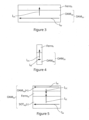
- Fig. 1 illustrates an OAM-MRAM cell 100 with three terminals materialized respectively as electrically conductive layers CL1, CL2 and CL3 for connections with the circuitry controlling the cell: the first terminal is used for circulating both of a writing current I W and a reading current I R , and the second and the third terminals are dedicated each to one of the writing current I W and the reading current I R .
- an OAM-MRAM cell includes a tri-layer element (TLE) comprising a ferromagnetic free layer Ferro f and a pinned ferromagnetic layer Ferro p separated by a spacer SP, and an OAM structure OAM Str adjacent to the ferromagnetic free layer Ferrof of the tri-layer element (TLE) as illustrated by Fig. 2 , this OAM structure.
- OAM Str being configured to generate the orbital torques upon circulation therein of a writing current Iw.
- the ensemble formed by the OAM structure OAM Str and the TLE is interposed between first and the third terminals, and the first and the second terminals are on the same side of the OAM structure OAM Str .
- a capping layer may be interposed between the tri-layer element (TLE) and the conductive line CL1 ; this capping layer can comprise an electrically conductive layer, an antiferromagnetic layer or a synthetic antiferromagnet (SAF) including a metallic non-magnetic spacer layer and a ferromagnetic layer or a plurality of such layers in alternating order; further, the cap layer may comprise any additional layer required by the practitioner to attain any specific functions and/or specifications for the OAM-MRAM cell.
- TLE tri-layer element
- SAF synthetic antiferromagnet
- the ferromagnetic layers Ferro f and Ferro p can comprise a ferromagnetic material including a metal or alloy having a specific perpendicular magnetic anisotropy whereby magnetizations of these layers are oriented substantially vertically (perpendicular to the plane of the ferromagnetic layers, configuration known as out-of-plane or perpendicular magnetic anisotropy PMA).
- Such metal or alloy can comprise FePt, FePd, CoPt, or a rare earth/transition metal alloy, in particular GdCo, TdFeCo, or Co, Fe, CoFe, Ni, CoNi, CoFeB, FeB.
- the ferromagnetic layers Ferro f and Ferro p can comprise a metal or alloy with magnetizations oriented parallel to the plane of the ferromagnetic layers Ferro f and Ferro p (in-plane magnetic anisotropy).
- Such metal or alloy can comprise FePt, FePd, CoPt, or a rare earth/transition metal alloy, in particular GdCo, TdFeCo, or Co, Fe, CoFe, Ni, CoNi, CoFeB, FeB.
- the thickness of the ferromagnetic layers Ferro f and Ferro p can be comprised between 0.5 nm and 100 nm and preferably between 1 and 3 nm.
- the spacer in made on a non-magnetic electrically conducting layer can comprise Cu, Ru, Cr or other metallic conductors known to lend themselves to the GMR effect.
- the spacer is a non-magnetic electrically insulating layer, for example an oxide layer such as an MgO layer of an Al 2 O 3 layer.
- the orbital torques (OT) are magnetic torques that act on the magnetization of a ferromagnetic layer that are generated by a charge current I W flowing within an OAM layer OAM lay part of the OAM structure OAM Str .
- the ferromagnetic layer has to be able to absorb orbital angular momentum for conversion into magnetic torques through spin-orbit interaction (SOI).
- SOI spin-orbit interaction
- materials and/or structures that are adequate to generate orbital torques OT from the OAM layer for practical applications are distinct from materials and/or structures that are adequate to generate spin orbit torques SOT as in SOT-MRAM.
- the present patent application has for objective to present structures and materials adequate to generate efficiently orbital torques for practical application in the control of the magnetic of the ferromagnetic free layer of a tri-layer element (TLE) in an MRAM cell.
- TLE tri-layer element
- the OAM layer OAM lay needs to comprise materials presenting an orbital conductivity ⁇ OH greater than 2 ⁇ 10 3 ( ⁇ /e) ( ⁇ .cm) -1 , i.e. Sc, Ti, V, Cr, Mn, Fe, Co, Y, Zr, Nb, Mo, Tc, Ru, Rh, Lu, Hf, Ta, W, Re, Os, Ir, Pt, Au and preferably greater than 6 ⁇ 10 3 ( ⁇ /e) ( ⁇ .cm) -1 , i.e.
- the orbital conductivity can be determined, for example, by ST-FMR or harmonic Hall voltage measurements.
- the orbital angular momentum carried by the orbital current is not directly absorbed by the ferromagnetic layer itself but is converted into a spin angular momentum carried by a spin current by an additional SO layer SO lay that is interposed between the OAM layer OHE lay and the ferromagnetic layer and into which the spin current is injected.
- a SO layer is a layer whose spin orbit interaction induces the conversion of an orbital current I OC into a spin current I SC , or, otherwise stated, the conversion of an orbital angular momentum into a spin angular momentum.
- the conversion is operated by Spin Orbit Interaction (SOI) in the SO layer SO lay , thus, for practical applications, the SO layer SO lay needs to comprise materials having a spin orbit interaction coefficient greater than 0.02 Ry, or heavy metals such W, Pt, Ta, Mo, Bi, and Hf or topological insulators such as Bi2Se3, BiSb and WTe2, for example ; these materials can be used individually as such, as oxides or as alloys of these materials or these oxides, or as multilayers of these materials, oxides or alloys.
- SOI Spin Orbit Interaction
- This OAM structure is configured to make use of the first mechanism, so that the writing current (I W ), when flowing within the OAM structure (OAM Str ), can write a magnetic state of the free ferromagnetic free layer Ferro f by injecting an orbital current I OC generated by the OAM layer OAM lay , directly into the ferromagnetic free layer Ferro f .
- the current I W flows within the OAM layer, thus alongside, or substantially in parallel to, the ferromagnetic free layer, so that the generated orbital current I OC flows perpendicularly to the ferromagnetic free layer and is injected therein.
- This orbital current is absorbed by the ferromagnetic free layer through spin-orbit interaction which results in the writing of the magnetic state of the ferromagnetic free layer by the generated orbital torques (OT) acting on its magnetization, as described in the article by Dongwook et al., "Orbital torque: Torque generation by orbital current injection", in Phys. Rev. Research 2, 013177 - published February 20, 2020 .
- This configuration is derived from the first configuration that makes use of the first mechanism with corresponding advantages, and one may refer to Fig. 3 for illustration.
- the ferromagnetic free layer presents intrinsic Perpendicular Magnetic Anisotropy PMA, which can be achieved by forming the ferromagnetic free layer as a multilayer of Co/Ni, Tb/Co or Co/Pt bi-layers.
- This configuration may also be applied to the ferromagnetic free layer of the 2 nd configuration, for example with one layer of the bi-layers having the-function of the SO layer SO lay .
- This configuration is derived from the 1 st configuration that makes use of the first mechanism.
- the ferromagnetic free layer Ferro f has a perpendicular magnetic anisotropy, an aspect ratio thickness/width greater than 1 that may favorize the apparition of perpendicular magnetization thanks to the shape anisotropy, and presents a thickness comprised between 3 nm and 100 nm.
- This configuration may also be applied to the ferromagnetic free layer of the 2 nd configuration.
- TLE tri-layer elements
- the OAM structure OAM Str of Fig. 2 is illustrated by Fig. 5 and comprises a SOT layer SOT lay distinct from the OAM layer OAM lay , a ferromagnetic writing layer Ferro w being interposed between the OAM layer OAM lay and the SOT layer SOT lay .
- the SOT mechanism designates spin orbit torques, and a SOT layer is defined as a layer configured to produce a spin current, I SC upon circulation of a charge current parallel to and within the SOT layer, of a magnitude and a sign function of a spin conductivity of the material constituting the SOT layer.
- an orbital current I OC generated by the OAM layer OAM lay and a spin current I SC generated by the SOT layer SOT lay each apply a respective torque to the magnetization of the ferromagnetic writing layer Ferro w .
- the spin conductivity of the SOT layer and the spin conductivity of the OAM layer are of opposite signs, as illustrated by the symbols "+" and "-" associated to the layers OAM lay and SOT lay in Fig. 5 .
- the SOT layer SOT lay comprises at least one material presenting an spin conductivity ⁇ SH greater than 0.3 ⁇ 10 3 ( ⁇ /e) ( ⁇ .cm) -1 , i.e. Ni, Rh, Pd, Ir and Pt, or greater than 0.8 ⁇ 10 3 ( ⁇ /e) ( ⁇ .cm) -1 ; these materials can be used individually as such, as oxides or as alloys of these materials or these oxides, or as multilayers of these materials, oxides or alloys.
- the spin conductivity can be determined, for example, by ST-FMR or harmonic Hall voltage measurements.
- An OAM structure having the present configuration and in which the OAM layer, the ferromagnetic free layer and the SO layer being respectively made of Ru, a multilayer of Co/Ni and Pt can be given as example.
- the SOT layer helps growing a thick composite ferromagnet composed of the two ferromagnetic writing layers by isolating the crystal structures of these two ferromagnet writing layers from one another so that the additional ferromagnetic writing layer can be easily grown on top of the ferromagnetic free layer.
- the ferromagnetic free layer Ferro f may constitute the additional ferromagnetic writing layer, in which case the tri-layer element TRE and the OAM structure OAM Str are intermixed.
- An exemplary structure is the following, the OAM layer, the ferromagnetic writing layer, the SOT layer and the additional ferromagnetic writing layer are respectively made of Ru, Ni, W and CoFeB.
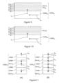
- This configuration is derived from the 2 nd configuration illustrated by Fig. 7 and thus makes use of the second mechanism detailed above and is illustrated by Fig. 8 .
- orbital currents I OC are generated by the OAM layers, injected into the respective SO layers that convert them into spin orbit currents I SC injected into the ferromagnetic writing layer where they apply respective torques to the magnetization of this layer.
- the spin conductivity of the bilayers SO lay /OAM lay each formed on a side of the ferromagnetic writing layer are of opposite signs, as illustrated by the symbols "+" and "-" associated in Fig. 8 .
- alloy and the bi-layer are a CoPt alloy and Co/Pt bi-layer, respectively, that can be associated with an OAM layer made of Ru.
- the material having a spin orbit interaction such as Pt, can convert orbital currents to spin currents, thereby writing the magnetic state of the ferromagnetic free layer.
- Fig. 9 illustrates the configuration with a Co/Pt multilayer, with the Pt layers indicated as Pt have the function of SO layers and the Co layers indicated as Co have the function of ferromagnetic layers.
- Such a configuration can be applied to any of the previous configurations, with the advantages that Ni is highly efficient to absorb the torque imparted by the orbital current, the Co/Ni multilayer presents an intrinsic perpendicular magnetic anisotropy which is favorable to the OAM-MRAM memory dots density and can be very thick.
- This OAM structure is configured to make use of the first mechanism.
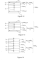
- the OAM structure OAM Str Fig. 2 comprises a plurality of OAM layers (OAM+, OAM-) and a plurality of ferromagnetic writing layers Ferro w that can be distributed according to the two variants (A) and (B) illustrated by Fig. 11 .
- the ferromagnetic writing layers Ferro w are sandwiched between two consecutive OAM layers having spin conductivity of opposite signs, OAM layers having a positive spin conductivity (indicated as OAM+) alternating with OHA layers having a negative spin conductivity (indicated as OAM-).
- two OAM layers having spin conductivity of opposite signs are adjacent to each other and interposed between two consecutive ferromagnetic writing layers Ferro w .
- a ferromagnetic writing layer Ferro w is interposed between the SO layer SO lay and the SOT layer SOT lay , the SO layer SO lay being interposed between the ferromagnetic writing layer Ferro w and the OAM layer OAM lay .
- OAM structure having the present configuration and in which the OAM layer, the SO layer, the ferromagnetic writing later and the SOT layer being respectively made of Ru, Pt, Co or a multilayer of Co/Ni, and Pt can be given as example.
- This OAM structure is configured to write the magnetic state of the ferromagnetic free layer Ferro f via a ferromagnetic writing layer Ferro w by using both of the first mechanism and the second mechanism, as illustrated by Fig. 13 .
- the SOI layer (SOI lay ) is interposed between the OAM layer (OAM lay ) and the ferromagnetic free layer (Ferro f ), and the ferromagnetic free layer (Ferro f ) is interposed between the SOI layer (SOI) and an additional OAM layer ( ad OAM lay ).
- the first mechanism is applied between the additional OAM layer and the ferromagnetic free layer
- the second mechanism is applied between the OAM layer, the SOI layer and the ferromagnetic free layer, as described previously by injection, respectively of an orbital current I OC and a spin current I SC into the ferromagnetic free layer.
- the currents I OC and I SC apply respective torques to the magnetization of the ferromagnetic free layer, and for these torques to have effects that add-up instead of cancelling one another, the spin conductivity of the additional OAM layer ad OAM lay and the spin conductivity of the bilayer formed by the OAM layer OAM lay and SO layer SO lay are of opposite signs, as illustrated by the symbols "+" and "-" associated to the layers ad OAM lay and the bilayer SO lay /OAM lay in Fig. 13 .
- This OAM structure is configured to write the magnetic state of the ferromagnetic free layer Ferro f by using both of the first mechanism and the second mechanism, as illustrated by Fig. 14 .
- orbital currents I OC are generated by the OAM layers, injected into the respective SO layers that convert them into spin orbit currents I SC injected into the ferromagnetic writing layers where they apply respective torques to the magnetization of these layers.
- the spin conductivity of the OAM layer alone and the bilayer formed by the OAM and SO layers are of opposite signs, as illustrated by the symbols "+" and "-" associated to the bilayers SO lay /OAM lay in Fig. 14 .
Landscapes
- Engineering & Computer Science (AREA)
- Computer Hardware Design (AREA)
- Hall/Mr Elements (AREA)
- Semiconductor Memories (AREA)
- Mram Or Spin Memory Techniques (AREA)
Priority Applications (1)
| Application Number | Priority Date | Filing Date | Title |
|---|---|---|---|
| EP22315221.6A EP4535359A3 (de) | 2022-09-30 | 2022-09-30 | Magnetische speicherzelle auf der basis des orbitalen drehimpuls |
Applications Claiming Priority (1)
| Application Number | Priority Date | Filing Date | Title |
|---|---|---|---|
| EP22315221.6A EP4535359A3 (de) | 2022-09-30 | 2022-09-30 | Magnetische speicherzelle auf der basis des orbitalen drehimpuls |
Publications (2)
| Publication Number | Publication Date |
|---|---|
| EP4535359A2 true EP4535359A2 (de) | 2025-04-09 |
| EP4535359A3 EP4535359A3 (de) | 2025-04-16 |
Family
ID=83899434
Family Applications (1)
| Application Number | Title | Priority Date | Filing Date |
|---|---|---|---|
| EP22315221.6A Pending EP4535359A3 (de) | 2022-09-30 | 2022-09-30 | Magnetische speicherzelle auf der basis des orbitalen drehimpuls |
Country Status (1)
| Country | Link |
|---|---|
| EP (1) | EP4535359A3 (de) |
Family Cites Families (1)
| Publication number | Priority date | Publication date | Assignee | Title |
|---|---|---|---|---|
| US10726893B2 (en) * | 2018-08-02 | 2020-07-28 | Sandisk Technologies Llc | Perpendicular SOT-MRAM memory cell using spin swapping induced spin current |
-
2022
- 2022-09-30 EP EP22315221.6A patent/EP4535359A3/de active Pending
Non-Patent Citations (4)
| Title |
|---|
| DONGJOON LEE: "Orbital Torque , in magnetic bilayers", NATURE COMMUNICATIONS, vol. 12, 2021, pages 6710 |
| DONGJOON LEE: "Orbital Torque in magnetic bilayers", NATURE COMMUNICATIONS, vol. 12, 2021, pages 6710 |
| DONGWOOK ET AL.: "Orbital torque: Torque generation by orbital current injection", PHYS. REV. RESEARCH, vol. 2, 20 February 2020 (2020-02-20), pages 013177 |
| SHILEI DING ET AL.: "Observation of the Orbital Rashba-Edelstein Magnetoresistance", PHYSICAL REVIEW LETTERS, vol. 128, no. 6, 10 February 2022 (2022-02-10), pages 067201 |
Also Published As
| Publication number | Publication date |
|---|---|
| EP4535359A3 (de) | 2025-04-16 |
Similar Documents
| Publication | Publication Date | Title |
|---|---|---|
| US10978234B2 (en) | Magnetic stack, multilayer, tunnel junction, memory point and sensor comprising such a stack | |
| JP4873338B2 (ja) | スピン注入デバイス及びこれを用いた磁気装置 | |
| US8072800B2 (en) | Magnetic element having perpendicular anisotropy with enhanced efficiency | |
| CN109560193B (zh) | 基于人工反铁磁固定层的磁性结构及sot-mram | |
| US9343658B2 (en) | Magnetic memory bits with perpendicular magnetization switched by current-induced spin-orbit torques | |
| CN109037434B (zh) | 基于人工反铁磁自由层的隧道结器件及磁性随机存储装置 | |
| US10651369B2 (en) | Magnetoresistive element and magnetic memory | |
| EP4236663B1 (de) | Spinstrom-magnetisierungsumkehrelement, magnetoresistives element und magnetischer speicher | |
| US7957181B2 (en) | Magnetic tunnel junction magnetic memory | |
| CN109244233B (zh) | 基于人工反铁磁固定层的磁性隧道结器件及随机存储装置 | |
| CN108010549B (zh) | 一种自旋极化电流发生器及其磁性装置 | |
| TWI530945B (zh) | Memory elements and memory devices | |
| JP2020031234A (ja) | スピン流磁化反転素子 | |
| JP4970113B2 (ja) | 磁気抵抗素子及び磁気メモリ | |
| TWI487155B (zh) | Memory elements and memory devices | |
| JP6972542B2 (ja) | スピン流磁化反転素子、磁気抵抗効果素子および磁気メモリ | |
| JP2007523480A (ja) | スピン転移を利用する磁気素子の熱支援スイッチングを提供するための方法及びシステム | |
| US20190189912A1 (en) | Structures Enabling Voltage Control of Oxidation Within Magnetic Heterostructures | |
| CN105684178A (zh) | 基于自旋力矩转移的磁性随机存取储存器(stt-mram)和磁头 | |
| US20130108889A1 (en) | Magnetoresistance Device and Memory Device Including the Magnetoresistance Device | |
| CN112652701A (zh) | 一种反铁磁结构及基于反铁磁结构的磁随机存储器 | |
| KR20130095753A (ko) | 자성 소자,및 상기 자성 소자로부터의 판독과 상기 자성 소자로의 기입 방법 | |
| EP4535359A2 (de) | Magnetische speicherzelle auf der basis des orbitalen drehimpuls | |
| JP2013012733A (ja) | 磁気スタックおよびこのようなスタックを備えたメモリセル | |
| WO2010125641A1 (ja) | トンネル磁気抵抗効果素子、それを用いた磁気メモリセル及びランダムアクセスメモリ |
Legal Events
| Date | Code | Title | Description |
|---|---|---|---|
| PUAI | Public reference made under article 153(3) epc to a published international application that has entered the european phase |
Free format text: ORIGINAL CODE: 0009012 |
|
| STAA | Information on the status of an ep patent application or granted ep patent |
Free format text: STATUS: THE APPLICATION HAS BEEN PUBLISHED |
|
| PUAB | Information related to the publication of an a document modified or deleted |
Free format text: ORIGINAL CODE: 0009199EPPU |
|
| PUAI | Public reference made under article 153(3) epc to a published international application that has entered the european phase |
Free format text: ORIGINAL CODE: 0009012 |
|
| PUAL | Search report despatched |
Free format text: ORIGINAL CODE: 0009013 |
|
| AK | Designated contracting states |
Kind code of ref document: A2 Designated state(s): AL AT BE BG CH CY CZ DE DK EE ES FI FR GB GR HR HU IE IS IT LI LT LU LV MC MK MT NL NO PL PT RO RS SE SI SK SM TR |
|
| AK | Designated contracting states |
Kind code of ref document: A3 Designated state(s): AL AT BE BG CH CY CZ DE DK EE ES FI FR GB GR HR HU IE IS IT LI LT LU LV MC MK MT NL NO PL PT RO RS SE SI SK SM TR |
|
| STAA | Information on the status of an ep patent application or granted ep patent |
Free format text: STATUS: REQUEST FOR EXAMINATION WAS MADE |
|
| 17P | Request for examination filed |
Effective date: 20251014 |