EP4535342A1 - Anzeigemodul mit mehreren scangruppen, modulare anzeigevorrichtung und verfahren zur steuerung davon - Google Patents
Anzeigemodul mit mehreren scangruppen, modulare anzeigevorrichtung und verfahren zur steuerung davon Download PDFInfo
- Publication number
- EP4535342A1 EP4535342A1 EP23889151.9A EP23889151A EP4535342A1 EP 4535342 A1 EP4535342 A1 EP 4535342A1 EP 23889151 A EP23889151 A EP 23889151A EP 4535342 A1 EP4535342 A1 EP 4535342A1
- Authority
- EP
- European Patent Office
- Prior art keywords
- scan
- display module
- driver
- comprised
- controller
- Prior art date
- Legal status (The legal status is an assumption and is not a legal conclusion. Google has not performed a legal analysis and makes no representation as to the accuracy of the status listed.)
- Pending
Links
Images



Classifications
-
- G—PHYSICS
- G06—COMPUTING OR CALCULATING; COUNTING
- G06F—ELECTRIC DIGITAL DATA PROCESSING
- G06F3/00—Input arrangements for transferring data to be processed into a form capable of being handled by the computer; Output arrangements for transferring data from processing unit to output unit, e.g. interface arrangements
- G06F3/14—Digital output to display device ; Cooperation and interconnection of the display device with other functional units
- G06F3/1423—Digital output to display device ; Cooperation and interconnection of the display device with other functional units controlling a plurality of local displays, e.g. CRT and flat panel display
- G06F3/1446—Digital output to display device ; Cooperation and interconnection of the display device with other functional units controlling a plurality of local displays, e.g. CRT and flat panel display display composed of modules, e.g. video walls
-
- G—PHYSICS
- G09—EDUCATION; CRYPTOGRAPHY; DISPLAY; ADVERTISING; SEALS
- G09F—DISPLAYING; ADVERTISING; SIGNS; LABELS OR NAME-PLATES; SEALS
- G09F9/00—Indicating arrangements for variable information in which the information is built-up on a support by selection or combination of individual elements
- G09F9/30—Indicating arrangements for variable information in which the information is built-up on a support by selection or combination of individual elements in which the desired character or characters are formed by combining individual elements
- G09F9/302—Indicating arrangements for variable information in which the information is built-up on a support by selection or combination of individual elements in which the desired character or characters are formed by combining individual elements characterised by the form or geometrical disposition of the individual elements
-
- G—PHYSICS
- G09—EDUCATION; CRYPTOGRAPHY; DISPLAY; ADVERTISING; SEALS
- G09F—DISPLAYING; ADVERTISING; SIGNS; LABELS OR NAME-PLATES; SEALS
- G09F9/00—Indicating arrangements for variable information in which the information is built-up on a support by selection or combination of individual elements
- G09F9/30—Indicating arrangements for variable information in which the information is built-up on a support by selection or combination of individual elements in which the desired character or characters are formed by combining individual elements
- G09F9/302—Indicating arrangements for variable information in which the information is built-up on a support by selection or combination of individual elements in which the desired character or characters are formed by combining individual elements characterised by the form or geometrical disposition of the individual elements
- G09F9/3026—Video wall, i.e. stackable semiconductor matrix display modules
-
- G—PHYSICS
- G09—EDUCATION; CRYPTOGRAPHY; DISPLAY; ADVERTISING; SEALS
- G09G—ARRANGEMENTS OR CIRCUITS FOR CONTROL OF INDICATING DEVICES USING STATIC MEANS TO PRESENT VARIABLE INFORMATION
- G09G3/00—Control arrangements or circuits, of interest only in connection with visual indicators other than cathode-ray tubes
- G09G3/006—Electronic inspection or testing of displays and display drivers, e.g. of LED or LCD displays
-
- G—PHYSICS
- G09—EDUCATION; CRYPTOGRAPHY; DISPLAY; ADVERTISING; SEALS
- G09G—ARRANGEMENTS OR CIRCUITS FOR CONTROL OF INDICATING DEVICES USING STATIC MEANS TO PRESENT VARIABLE INFORMATION
- G09G3/00—Control arrangements or circuits, of interest only in connection with visual indicators other than cathode-ray tubes
- G09G3/20—Control arrangements or circuits, of interest only in connection with visual indicators other than cathode-ray tubes for presentation of an assembly of a number of characters, e.g. a page, by composing the assembly by combination of individual elements arranged in a matrix no fixed position being assigned to or needed to be assigned to the individual characters or partial characters
- G09G3/22—Control arrangements or circuits, of interest only in connection with visual indicators other than cathode-ray tubes for presentation of an assembly of a number of characters, e.g. a page, by composing the assembly by combination of individual elements arranged in a matrix no fixed position being assigned to or needed to be assigned to the individual characters or partial characters using controlled light sources
- G09G3/30—Control arrangements or circuits, of interest only in connection with visual indicators other than cathode-ray tubes for presentation of an assembly of a number of characters, e.g. a page, by composing the assembly by combination of individual elements arranged in a matrix no fixed position being assigned to or needed to be assigned to the individual characters or partial characters using controlled light sources using electroluminescent panels
- G09G3/32—Control arrangements or circuits, of interest only in connection with visual indicators other than cathode-ray tubes for presentation of an assembly of a number of characters, e.g. a page, by composing the assembly by combination of individual elements arranged in a matrix no fixed position being assigned to or needed to be assigned to the individual characters or partial characters using controlled light sources using electroluminescent panels semiconductive, e.g. using light-emitting diodes [LED]
-
- G—PHYSICS
- G09—EDUCATION; CRYPTOGRAPHY; DISPLAY; ADVERTISING; SEALS
- G09G—ARRANGEMENTS OR CIRCUITS FOR CONTROL OF INDICATING DEVICES USING STATIC MEANS TO PRESENT VARIABLE INFORMATION
- G09G3/00—Control arrangements or circuits, of interest only in connection with visual indicators other than cathode-ray tubes
- G09G3/20—Control arrangements or circuits, of interest only in connection with visual indicators other than cathode-ray tubes for presentation of an assembly of a number of characters, e.g. a page, by composing the assembly by combination of individual elements arranged in a matrix no fixed position being assigned to or needed to be assigned to the individual characters or partial characters
- G09G3/22—Control arrangements or circuits, of interest only in connection with visual indicators other than cathode-ray tubes for presentation of an assembly of a number of characters, e.g. a page, by composing the assembly by combination of individual elements arranged in a matrix no fixed position being assigned to or needed to be assigned to the individual characters or partial characters using controlled light sources
- G09G3/30—Control arrangements or circuits, of interest only in connection with visual indicators other than cathode-ray tubes for presentation of an assembly of a number of characters, e.g. a page, by composing the assembly by combination of individual elements arranged in a matrix no fixed position being assigned to or needed to be assigned to the individual characters or partial characters using controlled light sources using electroluminescent panels
- G09G3/32—Control arrangements or circuits, of interest only in connection with visual indicators other than cathode-ray tubes for presentation of an assembly of a number of characters, e.g. a page, by composing the assembly by combination of individual elements arranged in a matrix no fixed position being assigned to or needed to be assigned to the individual characters or partial characters using controlled light sources using electroluminescent panels semiconductive, e.g. using light-emitting diodes [LED]
- G09G3/3208—Control arrangements or circuits, of interest only in connection with visual indicators other than cathode-ray tubes for presentation of an assembly of a number of characters, e.g. a page, by composing the assembly by combination of individual elements arranged in a matrix no fixed position being assigned to or needed to be assigned to the individual characters or partial characters using controlled light sources using electroluminescent panels semiconductive, e.g. using light-emitting diodes [LED] organic, e.g. using organic light-emitting diodes [OLED]
- G09G3/3216—Control arrangements or circuits, of interest only in connection with visual indicators other than cathode-ray tubes for presentation of an assembly of a number of characters, e.g. a page, by composing the assembly by combination of individual elements arranged in a matrix no fixed position being assigned to or needed to be assigned to the individual characters or partial characters using controlled light sources using electroluminescent panels semiconductive, e.g. using light-emitting diodes [LED] organic, e.g. using organic light-emitting diodes [OLED] using a passive matrix
-
- G—PHYSICS
- G09—EDUCATION; CRYPTOGRAPHY; DISPLAY; ADVERTISING; SEALS
- G09G—ARRANGEMENTS OR CIRCUITS FOR CONTROL OF INDICATING DEVICES USING STATIC MEANS TO PRESENT VARIABLE INFORMATION
- G09G5/00—Control arrangements or circuits for visual indicators common to cathode-ray tube indicators and other visual indicators
- G09G5/001—Arbitration of resources in a display system, e.g. control of access to frame buffer by video controller and/or main processor
-
- G—PHYSICS
- G09—EDUCATION; CRYPTOGRAPHY; DISPLAY; ADVERTISING; SEALS
- G09G—ARRANGEMENTS OR CIRCUITS FOR CONTROL OF INDICATING DEVICES USING STATIC MEANS TO PRESENT VARIABLE INFORMATION
- G09G5/00—Control arrangements or circuits for visual indicators common to cathode-ray tube indicators and other visual indicators
- G09G5/003—Details of a display terminal, the details relating to the control arrangement of the display terminal and to the interfaces thereto
- G09G5/006—Details of the interface to the display terminal
-
- G—PHYSICS
- G09—EDUCATION; CRYPTOGRAPHY; DISPLAY; ADVERTISING; SEALS
- G09G—ARRANGEMENTS OR CIRCUITS FOR CONTROL OF INDICATING DEVICES USING STATIC MEANS TO PRESENT VARIABLE INFORMATION
- G09G2300/00—Aspects of the constitution of display devices
- G09G2300/02—Composition of display devices
- G09G2300/026—Video wall, i.e. juxtaposition of a plurality of screens to create a display screen of bigger dimensions
-
- G—PHYSICS
- G09—EDUCATION; CRYPTOGRAPHY; DISPLAY; ADVERTISING; SEALS
- G09G—ARRANGEMENTS OR CIRCUITS FOR CONTROL OF INDICATING DEVICES USING STATIC MEANS TO PRESENT VARIABLE INFORMATION
- G09G2310/00—Command of the display device
- G09G2310/02—Addressing, scanning or driving the display screen or processing steps related thereto
- G09G2310/0202—Addressing of scan or signal lines
-
- G—PHYSICS
- G09—EDUCATION; CRYPTOGRAPHY; DISPLAY; ADVERTISING; SEALS
- G09G—ARRANGEMENTS OR CIRCUITS FOR CONTROL OF INDICATING DEVICES USING STATIC MEANS TO PRESENT VARIABLE INFORMATION
- G09G2310/00—Command of the display device
- G09G2310/02—Addressing, scanning or driving the display screen or processing steps related thereto
- G09G2310/0202—Addressing of scan or signal lines
- G09G2310/0213—Addressing of scan or signal lines controlling the sequence of the scanning lines with respect to the patterns to be displayed, e.g. to save power
-
- G—PHYSICS
- G09—EDUCATION; CRYPTOGRAPHY; DISPLAY; ADVERTISING; SEALS
- G09G—ARRANGEMENTS OR CIRCUITS FOR CONTROL OF INDICATING DEVICES USING STATIC MEANS TO PRESENT VARIABLE INFORMATION
- G09G2310/00—Command of the display device
- G09G2310/02—Addressing, scanning or driving the display screen or processing steps related thereto
- G09G2310/0264—Details of driving circuits
- G09G2310/0267—Details of drivers for scan electrodes, other than drivers for liquid crystal, plasma or OLED displays
-
- G—PHYSICS
- G09—EDUCATION; CRYPTOGRAPHY; DISPLAY; ADVERTISING; SEALS
- G09G—ARRANGEMENTS OR CIRCUITS FOR CONTROL OF INDICATING DEVICES USING STATIC MEANS TO PRESENT VARIABLE INFORMATION
- G09G2310/00—Command of the display device
- G09G2310/08—Details of timing specific for flat panels, other than clock recovery
-
- G—PHYSICS
- G09—EDUCATION; CRYPTOGRAPHY; DISPLAY; ADVERTISING; SEALS
- G09G—ARRANGEMENTS OR CIRCUITS FOR CONTROL OF INDICATING DEVICES USING STATIC MEANS TO PRESENT VARIABLE INFORMATION
- G09G2330/00—Aspects of power supply; Aspects of display protection and defect management
- G09G2330/02—Details of power systems and of start or stop of display operation
- G09G2330/021—Power management, e.g. power saving
-
- G—PHYSICS
- G09—EDUCATION; CRYPTOGRAPHY; DISPLAY; ADVERTISING; SEALS
- G09G—ARRANGEMENTS OR CIRCUITS FOR CONTROL OF INDICATING DEVICES USING STATIC MEANS TO PRESENT VARIABLE INFORMATION
- G09G2330/00—Aspects of power supply; Aspects of display protection and defect management
- G09G2330/10—Dealing with defective pixels
-
- G—PHYSICS
- G09—EDUCATION; CRYPTOGRAPHY; DISPLAY; ADVERTISING; SEALS
- G09G—ARRANGEMENTS OR CIRCUITS FOR CONTROL OF INDICATING DEVICES USING STATIC MEANS TO PRESENT VARIABLE INFORMATION
- G09G2330/00—Aspects of power supply; Aspects of display protection and defect management
- G09G2330/12—Test circuits or failure detection circuits included in a display system, as permanent part thereof
-
- G—PHYSICS
- G09—EDUCATION; CRYPTOGRAPHY; DISPLAY; ADVERTISING; SEALS
- G09G—ARRANGEMENTS OR CIRCUITS FOR CONTROL OF INDICATING DEVICES USING STATIC MEANS TO PRESENT VARIABLE INFORMATION
- G09G2360/00—Aspects of the architecture of display systems
- G09G2360/04—Display device controller operating with a plurality of display units
-
- G—PHYSICS
- G09—EDUCATION; CRYPTOGRAPHY; DISPLAY; ADVERTISING; SEALS
- G09G—ARRANGEMENTS OR CIRCUITS FOR CONTROL OF INDICATING DEVICES USING STATIC MEANS TO PRESENT VARIABLE INFORMATION
- G09G2360/00—Aspects of the architecture of display systems
- G09G2360/12—Frame memory handling
-
- G—PHYSICS
- G09—EDUCATION; CRYPTOGRAPHY; DISPLAY; ADVERTISING; SEALS
- G09G—ARRANGEMENTS OR CIRCUITS FOR CONTROL OF INDICATING DEVICES USING STATIC MEANS TO PRESENT VARIABLE INFORMATION
- G09G2370/00—Aspects of data communication
- G09G2370/04—Exchange of auxiliary data, i.e. other than image data, between monitor and graphics controller
-
- G—PHYSICS
- G09—EDUCATION; CRYPTOGRAPHY; DISPLAY; ADVERTISING; SEALS
- G09G—ARRANGEMENTS OR CIRCUITS FOR CONTROL OF INDICATING DEVICES USING STATIC MEANS TO PRESENT VARIABLE INFORMATION
- G09G2370/00—Aspects of data communication
- G09G2370/08—Details of image data interface between the display device controller and the data line driver circuit
Definitions
- the disclosure relates to a display module, a modular display apparatus, and a control method thereof, and more particularly, to a display module including a plurality of scan groups, a modular display apparatus including a plurality of display modules, and a control method thereof.
- size and form of the modular display apparatuses may be changed according to a number of display apparatuses, a size of the display apparatus that form the modular display apparatus, and the like.
- a driver IC for driving a plurality of scan lines and a plurality of data lines may be necessary, and if a number of pixels increase, a number of driver ICs may also increase.
- a number of scan groups may increase according to display apparatuses becoming large-scaled, and with the number of scan groups increasing, a number of pins required at the controller that transmits a PWM signal to a driver IC may also increase according to the number of scan groups increasing.
- a modular display apparatus includes a plurality of display modules, and a controller configured to control the plurality of display modules, and the plurality of display modules include a plurality of scan groups, respectively, the controller is configured to transmit an image signal corresponding to the respective display modules based on an image frame, and the respective scan groups included in a first display module from among the plurality of display modules include a plurality of scan lines arranged in one direction, a plurality of data lines arranged in a direction perpendicular to the plurality of scan lines, light emitting diodes (LEDs) generated at a cross area of the scan lines and the data lines, and at least one driver integrated circuit (IC) configured to provide a scan signal to the plurality of scan lines with a progressive scan method during a time period corresponding to the image frame, and provide the image signal to the data lines corresponding to the scan lines through which the scan signal is provided, and the plurality of scan groups included in the first display module is connected in a daisy chain method.
- LEDs light emitting diodes
- a control method of a modular display apparatus formed of a plurality of display modules includes transmitting an image signal corresponding to the plurality of display modules, respectively, based on an image frame by a controller, providing a scan signal to a plurality of scan lines included in a first display module with a progressive scan method during a time period corresponding to the image frame by at least one driver IC, and providing the image signal to data lines corresponding to scan lines through which the scan signal is provided from among a plurality of data lines arranged in a direction perpendicular to the plurality of scan lines by the at least one driver IC, and a plurality of scan groups included in the plurality of display modules, respectively, is connected in a daisy chain method.
- expressions "A or B,” “least one of A and/or B,” “one or more of A and/or B” and the like, may include all possible combinations of items enumerated together.
- “A or B,” “at least one of A and B” or “at least one of A or B” may indicate all of 1) a case where only A is included, 2) a case where only B is included, or 3) a case where both A and B are included.
- FIG. 1 is a diagram illustrating a modular display apparatus according to one or more embodiments.
- a modular display apparatus 100 may include a plurality of display modules 110. Each of the display modules 110 may be physically connected and form one display.
- the modular display apparatus 100 may be realized as a television (TV), but is not limited thereto.
- the modular display apparatus 100 may be applicable without limitation so long as it is an apparatus that includes a display function such as, for example, and without limitation, a video wall, a large format display (LFD), a digital signage, a digital information display (DID), a projector display, and the like.
- a display function such as, for example, and without limitation, a video wall, a large format display (LFD), a digital signage, a digital information display (DID), a projector display, and the like.
- the plurality of display modules 110 may be respectively realized as displays of various forms such as, for example, and without limitation, a liquid crystal display (LCD), an organic light-emitting diode (OLED), a liquid crystal on silicon (LCoS), a digital light processing (DLP), a quantum dot (QD) display panel, a quantum dot light-emitting diodes (QLED) micro light-emitting diodes ( ⁇ LED), a mini LED, and the like.
- the plurality of display modules 110 may respectively be realized as, for example, and without limitation, a touch screen coupled with a touch sensor, a flexible display, a rollable display, a 3-dimensional (3D) display, and the like.
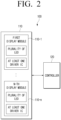
- FIG. 2 is a block diagram illustrating a modular display apparatus according to one or more embodiments.
- the modular display apparatus 100 may include the plurality of display modules 110, and the modular display apparatus 100 may display an image frame using the plurality of display modules 110.
- the modular display apparatus 100 may include the plurality of display modules 110 arranged in a matrix form (e.g., a 8x4 form).
- the 8x4 form is merely one embodiment for convenience of description, and arrangement forms, numbers, and the like of the plurality of display modules 110 that form the modular display apparatus 100 may be variously modified according to a specification of the modular display apparatus 100 (e.g., resolution, size, etc.), a manufacturing objective of a manufacturer, and the like.
- the plurality of display modules 110 included in the modular display apparatus 100 may respectively include a plurality of LEDs, and at least one driver IC.
- a first display module 110-1 may include a plurality of scan lines and a plurality of data lines (or, plurality of channels), and the plurality of scan lines may be arranged in one direction (e.g., horizontal direction), and the plurality of data lines may be arranged in a direction perpendicular to the plurality of scan lines (e.g., vertical direction).
- the plurality of display modules 110 may respectively operate in a passive matrix method.
- the controller 120 may include at least one processor, and the at least one processor may control the overall operation of the modular display apparatus 100.
- the plurality of operations may be performed by one processor, or performed by a plurality of processors.
- the first operation, the second operation, and the third operation may all be performed by a first processor, or the first operation and the second operation may be performed by the first processor (e.g., a generic-purpose processor) and the third operation may be performed by a second processor (e.g., an artificial intelligence dedicated processor).
- the at least one processor may be realized as a single core processor that includes one core, or as at least one multicore processor that includes a plurality of cores (e.g., a homogeneous multicore or a heterogeneous multicore). If the at least one processor is realized as a multicore processor, each of the cores included in the multicore processor may include a memory inside the processor such as a cache memory and an on-chip memory, and a common cache shared by the plurality of cores may be included in the multicore processor.
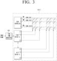
- FIG. 3 is a diagram illustrating a detailed configuration of any one from among a plurality of display modules according to one or more embodiments.
- the scan controller may sequentially turn-on the plurality of scan lines during one sub frame period (e.g., 260.4 ⁇ sec), and turn-on each of the scan lines 64 times during the time period corresponding to the image frame.
- one sub frame period e.g. 260.4 ⁇ sec
- the scan controller may divide one sub frame period back into an n-number of periods (a number of the plurality of scan lines), turn-on a switch of a first scan line (Scan line 1) during a first period T1, and control the LEDs corresponding to the first scan line (Scan line 1) to emit light.
- a switch of the remaining scan lines (Scan line 2 to Scan line n) may be turned-off during the first period T1.
- the LEDs corresponding to a second scan line (Scan line 2) may be controlled to emit light by turning-off the switch of the first scan line (Scan line 1), and turning-on a switch of the second scan line (Scan line 2).
- a switch of the remaining scan lines (Scan line 1, and Scan line 3 to Scan line n) except for the second scan line (Scan line 2) may be turned-off even during the second period T2.
- the whole pixels may all be configured to emit light during the sub frame period.
- the data lines of the plurality of scan lines (Scan line 1 to Scan line n), that is, the plurality of data lines may be configured so as to connect to at least one driver IC (e.g., a first driver IC to an nth driver IC), and if the plurality of scan lines are sequentially turned-on, the plurality of scan lines may be designated as a scan group.
- Each of the display modules 110 may include at least one scan group.
- the first display module 110-1 may include a plurality of scan groups, and the plurality of scan groups may be connected in a daisy chain method. The detailed description thereof will be provided below.
- the scan group may drive the plurality of data lines within the scan group using at least one driver IC.
- the driver IC may drive 32 scan lines and 16 data lines during the time period corresponding to one image frame, and if the scan group includes 32 scan lines and 160 data lines, the scan group may be driven by at least 10 driver ICs.
- the first driver IC may drive a first data line to a sixteenth data line
- a second driver IC may drive a seventeenth data line to a thirty second data line
- a tenth driver IC may drive a one hundred forty fifth data line to a one hundred sixtieth data line.
- the controller 120 may be configured to identify brightness of each of the pixels included in one scan group based on an image frame, and adjust a duty of a PWM signal based on the brightness of each of the pixels.
- the PWM signal may be referred to as an image signal, a driving signal, and the like, but will be collectively referred to as the PWM signal for convenience of description.
- the controller 120 may transmit the PWM signal to the first driver IC included in the first display module 110-1.
- the first driver IC may control a magnitude of current based on the received PWM signal, and adjust brightness of each of the pixels corresponding to the first driver IC within the scan group.
- the first driver IC may adjust brightness of each of the pixels corresponding to the first driver IC through data lines connected to the first driver IC.
- the controller 120 may transmit a PWM signal corresponding to the driver ICs included within the scan group, that is, each of the first driver IC to the tenth driver IC to the first driver IC. Because the driver ICs included within the scan group according to an example are connected according to the daisy chain method, the first driver IC may sequentially transmit the PWM signal received from the controller 120 to the remaining driver ICs (i.e., a second driver IC to an nth driver IC).
- the nth driver IC may control a magnitude of current based on the PWM signal received from a nth-1 driver IC, and adjust brightness of each of the pixels corresponding to the nth driver IC within the scan group. For example, the nth driver IC may adjust brightness of each of the pixels corresponding to the nth driver IC through data lines connected to the nth driver IC.
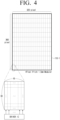
- FIG. 4 is a diagram illustrating a modular display apparatus of a first pixel pitch according to one or more embodiments.
- Distance e.g., a pixel pitch between the plurality of LEDs included in each of the display modules, according to one or more embodiments of the disclosure, may be variously modified according to a manufacturing objective of a manufacturer.
- one driver IC may drive 30 scan lines and 16 data lines during the time period corresponding to one image frame, and if the scan group includes 30 scan lines and 320 data lines, the one scan group may be driven by at least 20 driver ICs.
- the controller 120 may transmit a PWM signal that corresponds to each of the 20 driver ICs included in the scan group to the first driver IC (e.g., the driver IC to which the first data line to the sixteenth data line are connected).
- the first driver IC may transmit a PWM signal corresponding to each of the remaining 19 driver ICs to the second driver IC (e.g., the driver IC to which the seventeenth data line to the thirty second data line are connected).
- the first display module 110-1 may include 12 scan groups.
- FIG. 5 is a diagram illustrating a plurality of scan groups included in a modular display apparatus of a first pixel pitch according to one or more embodiments.
- a size of the display module is the same, a number of the plurality of LEDs mounted to a display module may decrease as the pixel pitch, that is, a distance between the plurality of LED devices mounted to the display module increases.
- a resolution of the display module may decrease because the number of the plurality of LEDs mountable to the display module decreases.
- the controller 120 of the modular display apparatus 100 may be connected to each of the scan groups (e.g., a first scan group to a third scan group) included in the first display module 110-1, and transmit the PWM signal to plurality of scan groups, respectively.
- the scan groups e.g., a first scan group to a third scan group
- the first display module 110-1 may include 3 scan groups, and the controller 120 may transmit a PWM signal corresponding to each of 5 driver ICs included in the first scan group (SCAN GROUP 1) to the first driver IC of the first scan group (SCAN GROUP 1).
- the first driver IC from among the 5 driver ICs included in the first scan group may sequentially transmit the PWM signal corresponding to the remaining driver ICs (e.g., the second driver IC to a fifth driver IC) connected according to the daisy chain method.
- the controller 120 may be connected to each of the scan groups (e.g., the first scan group to the third scan group) included in each of a second display module 110-2 to the sixteenth display module 110-16, and transmit the PWM signal to the plurality of scan groups, respectively.
- the scan groups e.g., the first scan group to the third scan group
- the controller 120 may be connected to each of the scan groups (e.g., the first scan group to the third scan group) included in each of a second display module 110-2 to the sixteenth display module 110-16, and transmit the PWM signal to the plurality of scan groups, respectively.
- an nth display module 110-n may include 3 scan groups, and the controller 120 may transmit the PWM signal corresponding to each of the 5 driver ICs included in the first scan group (SCAN GROUP 1) to the first driver IC of the first scan group (SCAN GROUP 1).
- the first driver IC from among the 5 driver ICs included in the first scan group may sequentially transmit the PWM signal corresponding to the remaining driver ICs (e.g., the second driver IC to the fifth driver IC) connected according to the daisy chain method.
- the controller 120 may transmit a PWM signal to each of the 12 scan groups included in the first display module 110-1 with the 1.5 mm pixel pitch and control the plurality of LEDs corresponding to the 320x360 resolution, but may control the plurality of LEDs corresponding to the 320x360 resolution by transmitting a PWM signal to the 3 scan groups, that is, to each of a total of 48 scan groups included in each of the first display module 110-1 to the sixteenth display module 110-16 with the 6.0 mm pixel pitch.
- the plurality of scan groups included in each of the display modules 110 may be connected with the daisy chain method. The detailed description thereof will be provided with reference to FIG. 8 .
- FIG. 8 is a diagram illustrating a plurality of scan groups connected in a daisy chain method according to one or more embodiments.
- the controller 120 may obtain a PWM signal corresponding to the first display module 110-1.
- the PWM signal corresponding to the first display module 110-1 may a PWM signal buffered to correspond to a connection order of the plurality of scan groups (e.g., the first scan group to the third scan group) according to the daisy chain method included in the first display module 110-1.
- the detailed description thereof will be provided below.
- the PWM signal corresponding to the first scan group may include a PWM signal corresponding to each of the 20 driver ICs included in the first scan group.
- the PWM signal corresponding to the first scan group may drive 320 data lines. That is, a size of the PWM signal corresponding to the first scan group that the controller 120 is configured to transmit to the first scan group may correspond to a bandwidth loadable by the controller 120 during the time period corresponding to the image frame or a maximum size of a signal transmittable by the controller 120 to the first driver IC included in the first scan group.
- the PWM signal corresponding to the first scan group may include a PWM signal corresponding to each of the 5 driver ICs included in the first scan group.
- the PWM signal corresponding to the first scan group may drive 80 data lines.
- a size of the PWM signal corresponding to the first scan group that the controller 120 transmits to the first scan group may be less than a bandwidth loadable by the controller 120 from the memory stored with the image frame during the time period corresponding to the image frame, or less than a maximum size of a signal transmittable by the controller 120 to the first driver IC included in the first scan group.
- the controller 120 may transmit a PWM signal corresponding to the first display module 110-1, and the PWM signal corresponding to the first display module 110-1 may include a PWM signal corresponding to the first display module 110-1, a PWM signal corresponding to the first scan group, a PWM signal corresponding to a second scan group, and a PWM signal corresponding to the third scan group altogether.
- the PWM signal corresponding to the first scan group may drive 240 data lines. Accordingly, a size of the PWM signal corresponding to the first scan group that the controller 120 transmits to the first scan group may be less than a bandwidth loadable by the controller 120 from the memory stored with the image frame during the time period corresponding to the image frame, or less than a maximum size of a signal transmittable by the controller 120 to the first driver IC included in the first scan group.
- the controller 120 transmits the PWM signal to the first driver IC included in the first scan group and not transmit the PWM signal to the first driver IC included in each of the scan groups (the first scan group to the third scan group) included in the first display module 110-1, the PWM signal corresponding to each of the scan groups included in the first display module 110-1 may be transmitted using 1 pin.
- the controller 120 may be realized with a relatively low-performance and low-cost FPGA.
- FIG. 9 is a diagram illustrating an image signal according to one or more embodiments.
- the controller 120 may transmit the PWM signal corresponding to the first display module 110-1 to the first display module 110-1.
- the controller 120 may transmit a PWM signal (1A -> 2A -> 3A -> 4A -> 5A) corresponding to each of the first driver IC to the fifth driver IC of the first scan group to the first driver IC of the first scan group included in the first display module 110-1.
- the PWM signal transmitted to the first driver IC of the first scan group by the controller 120 may be a PWM signal (1A -> 2A -> 3A -> 4A -> 5A) buffered to correspond to a connection order of the first driver IC to the fifth driver IC according to the daisy chain method.
- the controller 120 may transmit a PWM signal (1B -> 2B -> 3B -> 4B -> 5B) corresponding to each of the first driver IC to the fifth driver IC of the second scan group to the first driver IC of the second scan group included in the first display module 110-1, and transmit a PWM signal (1C -> 2C -> 3C -> 4C -> 5C) corresponding to each of the first driver IC to the fifth driver IC of the third scan group to the first driver IC of the third scan group included in the first display module 110-1.
- At least 3 pins are required because the controller 120 is connected to each of the first scan group to the third scan group.
- the controller 120 may obtain a PWM signal corresponding to the first display module 110-1 buffered to correspond to the connection order of the plurality of scan groups.
- the controller 120 may obtain a PWM signal corresponding to the first display module 110-1 by arranging the PWM signal corresponding to each of the driver ICs (e.g., 15 driver ICs) included in the first display module 110-1 in an order of a PWM signal 1C corresponding to the fifth driver IC of the third scan group -> ... -> a PWM signal 5C corresponding to the first driver IC of the third scan group -> PWM signal 1B corresponding to the fifth driver IC of the second scan group -> ... -> a PWM signal 5B corresponding to the first driver IC of the second scan group -> a PWM signal 1A corresponding to the fifth driver IC of the first scan group -> ...
- the driver ICs e.g., 15 driver ICs
- -> a PWM signal 5A corresponding to the first driver IC of the first scan group (i.e., 1C -> 2C -> 3C -> 4C -> 5C -> 1B -> 2B -> 3B -> 4B -> 5B -> 1A -> 2A -> 3A -> 4A -> 5A) taking into consideration i) the connection order according to the daisy chain method between the plurality of scan groups and ii) the connection order according to the daisy chain method between the driver ICs within the scan group.
- the controller 120 may transmit the PWM corresponding to the first display module 110-1 to the first driver IC included in the first scan group included in the first display module 110-1.
- the controller 120 may obtain a PWM signal corresponding to the first display module 110-1, a PWM signal corresponding to the second display module 110-2, and a PWM signal corresponding to a third display module 110-3, respectively.
- a driver IC e.g., fifth driver IC
- a scan group e.g., third scan group
- the fifth driver IC of the driver IC e.g., first scan group
- the fifth driver IC of the second scan group e.g., and the fifth driver IC of the third scan group from among the driver ICs included in each of the scan groups transmitting the output signal to the controller 120
- the controller 120 may include a multiplexer IC, and the first display module 110-1 may include the switch IC.
- a multiplexer IC and a switch IC may be connected and a bidirectional communication between the controller 120 and the first display module 110-1 may be possible.
- the multiplexer IC may transmit a PWM signal corresponding to the first display module 110-1 to the switch IC.
- the switch IC may transmit, based on the PWM signal corresponding to the first display module 110-1 being received from the controller 120, the PWM signal to the first driver IC included in the first scan group from among the plurality of scan groups included in the first display module 110-1.
- the switch IC may transmit, based on an output signal being received from the driver IC (e.g., fifth driver IC) connected last according to the daisy chain method from among the driver ICs included in a scan group (e.g., third scan group) connected last according to the daisy chain method from among the plurality of scan groups, the output signal to the controller 120.
- the multiplexer IC may transmit, based on the output signal being received from the switch IC, the output signal to the TCON included in the controller 120.
- the modular display apparatus 100 may further include a memory.
- the memory may store data necessary for the various embodiments of the disclosure.
- the memory may be realized in a memory form embedded to the modular display apparatus 100 according to data storage use, or realized in a memory form attachable to or detachable from the modular display apparatus 100.
- data for the driving of the modular display apparatus 100 may be stored in a memory embedded to the modular display apparatus 100, and data for an expansion function of the modular display apparatus 100 may be stored in a memory attachable to and detachable from the modular display apparatus 100.
- the memory embedded in the modular display apparatus 100 may be realized as at least one from among a volatile memory (e.g., a dynamic random access memory (DRAM), a static RAM (SRAM), or a synchronous dynamic RAM (SDRAM)), or a non-volatile memory (e.g., one time programmable read only memory (OTPROM), programmable ROM (PROM), erasable and programmable ROM (EPROM), electrically erasable and programmable ROM (EEPROM), mask ROM, flash ROM, a flash memory (e.g., NAND flash or NOR flash), a hard disk drive (HDD) or a solid state drive (SSD)).
- a volatile memory e.g., a dynamic random access memory (DRAM),
- the memory may be realized in a form such as, for example, and without limitation, a memory card (e.g., a compact flash (CF), a secure digital (SD), a micro secure digital (micro-SD), a mini secure digital (mini-SD), an extreme digital (xD), a multi-media card (MMC), etc.), an external memory (e.g., USB memory) connectable to a USB port (e.g., USB memory), or the like.
- a memory card e.g., a compact flash (CF), a secure digital (SD), a micro secure digital (micro-SD), a mini secure digital (mini-SD), an extreme digital (xD), a multi-media card (MMC), etc.
- an external memory e.g., USB memory connectable to a USB port (e.g., USB memory), or the like.
- the memory may store at least one instruction or a computer program including the instructions for controlling the modular display apparatus 100.
- the memory may store image data which includes the plurality of image frames.
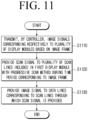
- FIG. 11 is a flowchart illustrating a control method of a modular display apparatus according to one or more embodiments.
- a control method of the modular display apparatus formed of the plurality of display modules may include, first, transmitting, by the controller, image signals corresponding respectively to the plurality of display modules based on an image frame (S1110).
- a scan signal is provided, by the at least one driver IC, to the plurality of scan lines included in the first display module with a progressive scan method during the time period corresponding to the image frame (S1120).
- An image signal is provided, by the at least one driver IC, to the data line corresponding to the scan line through which the scan signal is provided from among the plurality of data lines arranged in a direction perpendicular to the plurality of scan lines (S1130).
- the plurality of scan groups included in each of the display modules may be connected in the daisy chain method.
- step S1110 of transmitting the image signal may include obtaining an image signal corresponding to the first display module from an image frame and transmitting the image signal corresponding to the first display module, and the image signal corresponding to the first display module may be buffered to correspond to the connection order of the plurality of scan groups according to the daisy chain method included in the first display module.
- the transmitting the image signal corresponding to the first display module may include transmitting the image signal to the at least one driver IC included in the first scan group from among the plurality of scan groups included in the first display module and transmitting, by the at least one driver IC included in the first scan group, the image signal to the at least one driver IC included in the second scan group included in the first display module according to the daisy chain method.
- the size of the image signal corresponding to each of the display modules may correspond to a bandwidth loadable during the time period corresponding to the image frame by the controller.
- the control method may further include the at least one driver IC included in the scan group connected last according to the daisy chain method from among the plurality of scan groups included in the first display module from among the plurality of display modules transmitting an output signal to the controller and identifying open LED information corresponding to the first display module based on the output signal.
- the plurality of display modules may respectively include the switch IC
- the transmitting the image signal may include receiving an image signal corresponding to the first display module from the controller by the switch IC included in the first display module and transmitting the image signal to the at least one driver IC included in the first scan group from among the plurality of scan groups included in the first display module
- the transmitting the output signal may include transmitting the output signal to the controller based on the output signal being received from the at least one driver IC included in the scan group connected last from among the plurality of scan groups included in the first display module by the switch IC included in the first display module.
- the controller may include the multiplexer IC, the transmitting the image signal may include transmitting the image signal corresponding to the first display module to the switch IC by the multiplexer IC, and the identifying open LED information may include receiving an output signal from the switch IC by the multiplexer IC and identifying open LED information corresponding to the first display module based on the output signal.
- the identifying open LED information may include identifying whether an error of the plurality of LEDs included in the first display module occurred based on the open LED information.
- the transmitting the image signal may include transmitting the image signal corresponding to the second display module to the at least one driver IC included in the scan group connected first according to the daisy chain method from among the plurality of scan groups included in the second display module from among the plurality of display modules, and the control method according to an example may further include receiving the output signal corresponding to the second display module from the at least one driver IC included in the scan group connected last according to the daisy chain method from among the plurality of scan groups included in the second display module.
- the various embodiments of the disclosure may be applicable to not only electronic apparatuses, but also to all types of electronic apparatuses that include the display.
- embodiments described above may be realized in a recordable medium which is readable by a computer or a device similar to the computer using software, hardware, or the combination of software and hardware.
- embodiments described herein may be realized by the processor itself.
- embodiments such as the procedures and functions described herein may be realized with a separate software.
- the respective software may perform one or more functions and operations described herein.
- the computer instructions for performing processing operations in an electronic apparatus according to the various embodiments described above may be stored in a non-transitory computer-readable medium.
- the computer instructions stored in this non-transitory computer-readable medium may cause a specific device to perform a processing operation from an electronic apparatus according to the above-described various embodiments when executed by a processor of the specific device.
- the non-transitory computer readable medium may refer to a medium that stores data semi-permanently rather than storing data for a very short time, such as a register, a cache, a memory, or the like, and is readable by a device.
- Specific examples of the non-transitory computer readable medium may include, for example, and without limitation, a compact disc (CD), a digital versatile disc (DVD), a hard disc, a Blu-ray disc, a USB, a memory card, a ROM, and the like.
Landscapes
- Engineering & Computer Science (AREA)
- Theoretical Computer Science (AREA)
- Physics & Mathematics (AREA)
- General Physics & Mathematics (AREA)
- Computer Hardware Design (AREA)
- Multimedia (AREA)
- Human Computer Interaction (AREA)
- General Engineering & Computer Science (AREA)
- Control Of Indicators Other Than Cathode Ray Tubes (AREA)
Applications Claiming Priority (2)
| Application Number | Priority Date | Filing Date | Title |
|---|---|---|---|
| KR1020220150150A KR20240069041A (ko) | 2022-11-11 | 2022-11-11 | 복수의 스캔 그룹을 포함하는 디스플레이 모듈, 모듈러 디스플레이 장치 및 그 제어 방법 |
| PCT/KR2023/017894 WO2024101893A1 (ko) | 2022-11-11 | 2023-11-08 | 복수의 스캔 그룹을 포함하는 디스플레이 모듈, 모듈러 디스플레이 장치 및 그 제어 방법 |
Publications (2)
| Publication Number | Publication Date |
|---|---|
| EP4535342A1 true EP4535342A1 (de) | 2025-04-09 |
| EP4535342A4 EP4535342A4 (de) | 2025-06-18 |
Family
ID=91028082
Family Applications (1)
| Application Number | Title | Priority Date | Filing Date |
|---|---|---|---|
| EP23889151.9A Pending EP4535342A4 (de) | 2022-11-11 | 2023-11-08 | Anzeigemodul mit mehreren scangruppen, modulare anzeigevorrichtung und verfahren zur steuerung davon |
Country Status (3)
| Country | Link |
|---|---|
| US (2) | US12474882B2 (de) |
| EP (1) | EP4535342A4 (de) |
| CN (1) | CN119768855A (de) |
Families Citing this family (1)
| Publication number | Priority date | Publication date | Assignee | Title |
|---|---|---|---|---|
| EP4535341A4 (de) * | 2022-11-23 | 2025-10-29 | Samsung Electronics Co Ltd | Anzeigemodul, modulare anzeigevorrichtung mit mehreren anzeigemodulen und steuerungsverfahren dafür |
Family Cites Families (20)
| Publication number | Priority date | Publication date | Assignee | Title |
|---|---|---|---|---|
| JP4665375B2 (ja) * | 2000-07-28 | 2011-04-06 | 日亜化学工業株式会社 | ディスプレイ装置 |
| JP2011520231A (ja) | 2008-05-06 | 2011-07-14 | コーニンクレッカ フィリップス エレクトロニクス エヌ ヴィ | Led駆動ユニット |
| KR100903822B1 (ko) | 2008-10-17 | 2009-06-25 | 주식회사 아크로텍 | 발광 다이오드 백라이트 유닛 및 이를 포함하는 디스플레이장치 |
| US8207954B2 (en) * | 2008-11-17 | 2012-06-26 | Global Oled Technology Llc | Display device with chiplets and hybrid drive |
| US8344659B2 (en) | 2009-11-06 | 2013-01-01 | Neofocal Systems, Inc. | System and method for lighting power and control system |
| US20120299480A1 (en) * | 2009-11-06 | 2012-11-29 | Neofocal Systems, Inc. | System And Method For Current Modulated Data Transmission |
| US8779696B2 (en) | 2011-10-24 | 2014-07-15 | Advanced Analogic Technologies, Inc. | Low cost LED driver with improved serial bus |
| US9740276B2 (en) * | 2013-02-12 | 2017-08-22 | Nec Display Solutions, Ltd. | Electronic device and method for controlling electronic device |
| US9582237B2 (en) * | 2013-12-31 | 2017-02-28 | Ultravision Technologies, Llc | Modular display panels with different pitches |
| CN104252841B (zh) | 2014-09-15 | 2017-03-08 | 西安诺瓦电子科技有限公司 | Led显示控制方法及控制卡、led显示屏系统 |
| KR102088683B1 (ko) | 2015-09-04 | 2020-03-13 | 삼성전자주식회사 | 영상표시장치 및 영상표시장치의 구동 방법 |
| KR102457644B1 (ko) | 2016-04-05 | 2022-10-20 | 엘지디스플레이 주식회사 | 표시장치 및 이의 동작방법 |
| KR102627278B1 (ko) | 2016-09-22 | 2024-01-23 | 엘지디스플레이 주식회사 | 멀티비전 시스템 |
| WO2020008585A1 (ja) | 2018-07-05 | 2020-01-09 | 三菱電機株式会社 | Led表示システム、led表示装置およびled表示制御装置 |
| KR102608951B1 (ko) | 2018-09-06 | 2023-12-04 | 삼성전자주식회사 | 디스플레이 장치 및 디스플레이 장치의 제어방법 |
| US20200211446A1 (en) | 2018-09-10 | 2020-07-02 | Ultravision Technologies, Llc | Display Panels with Embedded Control System |
| KR102687644B1 (ko) * | 2019-07-12 | 2024-07-24 | 삼성전자주식회사 | 전자 장치 및 그 제어 방법 |
| US11982905B2 (en) | 2020-05-22 | 2024-05-14 | Apple Inc. | Electronic device display with a backlight having light-emitting diodes and driver integrated circuits in an active area |
| KR102812629B1 (ko) | 2020-10-08 | 2025-05-27 | 삼성전자주식회사 | 백라이트 시스템, 이를 포함하는 디스플레이 장치 및 백라이트 시스템의 데이터 전달 방법 |
| US11488548B2 (en) | 2020-10-08 | 2022-11-01 | Samsung Electronics Co., Ltd. | Backlight system, display device including the backlight system and method of transferring data in the backlight system |
-
2023
- 2023-11-08 EP EP23889151.9A patent/EP4535342A4/de active Pending
- 2023-11-08 CN CN202380063134.5A patent/CN119768855A/zh active Pending
- 2023-12-20 US US18/391,083 patent/US12474882B2/en active Active
-
2025
- 2025-11-13 US US19/388,513 patent/US20260072633A1/en active Pending
Also Published As
| Publication number | Publication date |
|---|---|
| EP4535342A4 (de) | 2025-06-18 |
| CN119768855A (zh) | 2025-04-04 |
| US12474882B2 (en) | 2025-11-18 |
| US20260072633A1 (en) | 2026-03-12 |
| US20240160397A1 (en) | 2024-05-16 |
Similar Documents
| Publication | Publication Date | Title |
|---|---|---|
| US20260072633A1 (en) | Display module comprising a plurality of scan groups, modular display apparatus and control method thereof | |
| US10134328B2 (en) | Display device and driving method thereof | |
| US9858898B2 (en) | Display driving apparatus and display driving method thereof | |
| KR102608951B1 (ko) | 디스플레이 장치 및 디스플레이 장치의 제어방법 | |
| US20180061299A1 (en) | Timing controller and display driving circuit including the same | |
| JP2008107777A (ja) | タイミングコントローラ及びこれを備える液晶表示装置 | |
| KR102728919B1 (ko) | 유기 발광 표시 장치 | |
| KR20210019900A (ko) | 디스플레이 장치 및 그 제어 방법 | |
| CN117456939B (zh) | 背光单元的控制方法及设备 | |
| US10607550B2 (en) | Digital control driving method and driving display device | |
| KR20240069041A (ko) | 복수의 스캔 그룹을 포함하는 디스플레이 모듈, 모듈러 디스플레이 장치 및 그 제어 방법 | |
| CN116798350A (zh) | 电子装置 | |
| US10665152B2 (en) | Light emitting diode display device and method of operating the same | |
| KR20200114691A (ko) | 디스플레이 장치 및 그 제어 방법 | |
| KR20200123640A (ko) | 디스플레이 장치 및 그 제어 방법 | |
| EP4535340A1 (de) | Anzeigevorrichtung mit mehreren treiber-ic's, modulare anzeigevorrichtung und steuerverfahren dafür | |
| CN114093314B (zh) | 一种地址设定方法、设备和显示装置 | |
| KR102816080B1 (ko) | 디스플레이 시스템 | |
| EP4535341A1 (de) | Anzeigemodul, modulare anzeigevorrichtung mit mehreren anzeigemodulen und steuerungsverfahren dafür | |
| EP4730313A1 (de) | Modulare anzeigevorrichtung und verfahren zur steuerung davon | |
| US12573339B2 (en) | Display device operating with time-division and control method thereof | |
| KR102672652B1 (ko) | 디스플레이 장치 및 그의 데이터 전송 방법 | |
| KR20240067679A (ko) | 복수의 드라이버 ic를 포함하는 디스플레이 장치, 모듈러 디스플레이 장치 및 그 제어 방법 | |
| US20260044297A1 (en) | Display apparatus for power supply control, modular display apparatus and control method thereof | |
| KR20240076313A (ko) | 디스플레이 모듈, 복수의 디스플레이 모듈을 포함하는 모듈러 디스플레이 장치 및 그 제어 방법 |
Legal Events
| Date | Code | Title | Description |
|---|---|---|---|
| STAA | Information on the status of an ep patent application or granted ep patent |
Free format text: STATUS: THE INTERNATIONAL PUBLICATION HAS BEEN MADE |
|
| PUAI | Public reference made under article 153(3) epc to a published international application that has entered the european phase |
Free format text: ORIGINAL CODE: 0009012 |
|
| STAA | Information on the status of an ep patent application or granted ep patent |
Free format text: STATUS: REQUEST FOR EXAMINATION WAS MADE |
|
| 17P | Request for examination filed |
Effective date: 20241231 |
|
| AK | Designated contracting states |
Kind code of ref document: A1 Designated state(s): AL AT BE BG CH CY CZ DE DK EE ES FI FR GB GR HR HU IE IS IT LI LT LU LV MC ME MK MT NL NO PL PT RO RS SE SI SK SM TR |
|
| A4 | Supplementary search report drawn up and despatched |
Effective date: 20250515 |
|
| RIC1 | Information provided on ipc code assigned before grant |
Ipc: G09G 3/3216 20160101ALI20250512BHEP Ipc: G06F 3/14 20060101ALI20250512BHEP Ipc: G09F 9/302 20060101ALI20250512BHEP Ipc: G09G 5/00 20060101ALI20250512BHEP Ipc: G09G 3/00 20060101ALI20250512BHEP Ipc: G09G 3/32 20160101AFI20250512BHEP |
|
| DAV | Request for validation of the european patent (deleted) | ||
| DAX | Request for extension of the european patent (deleted) |