EP4534968A1 - Pressure sensor - Google Patents
Pressure sensor Download PDFInfo
- Publication number
- EP4534968A1 EP4534968A1 EP23815581.6A EP23815581A EP4534968A1 EP 4534968 A1 EP4534968 A1 EP 4534968A1 EP 23815581 A EP23815581 A EP 23815581A EP 4534968 A1 EP4534968 A1 EP 4534968A1
- Authority
- EP
- European Patent Office
- Prior art keywords
- sensor chip
- pressure
- housing
- pressure sensor
- strain
- Prior art date
- Legal status (The legal status is an assumption and is not a legal conclusion. Google has not performed a legal analysis and makes no representation as to the accuracy of the status listed.)
- Pending
Links
Images



Classifications
-
- G—PHYSICS
- G01—MEASURING; TESTING
- G01L—MEASURING FORCE, STRESS, TORQUE, WORK, MECHANICAL POWER, MECHANICAL EFFICIENCY, OR FLUID PRESSURE
- G01L19/00—Details of, or accessories for, apparatus for measuring steady or quasi-steady pressure of a fluent medium insofar as such details or accessories are not special to particular types of pressure gauges
- G01L19/0007—Fluidic connecting means
- G01L19/0023—Fluidic connecting means for flowthrough systems having a flexible pressure transmitting element
-
- G—PHYSICS
- G01—MEASURING; TESTING
- G01L—MEASURING FORCE, STRESS, TORQUE, WORK, MECHANICAL POWER, MECHANICAL EFFICIENCY, OR FLUID PRESSURE
- G01L19/00—Details of, or accessories for, apparatus for measuring steady or quasi-steady pressure of a fluent medium insofar as such details or accessories are not special to particular types of pressure gauges
- G01L19/06—Means for preventing overload or deleterious influence of the measured medium on the measuring device or vice versa
- G01L19/0627—Protection against aggressive medium in general
- G01L19/0654—Protection against aggressive medium in general against moisture or humidity
-
- G—PHYSICS
- G01—MEASURING; TESTING
- G01L—MEASURING FORCE, STRESS, TORQUE, WORK, MECHANICAL POWER, MECHANICAL EFFICIENCY, OR FLUID PRESSURE
- G01L19/00—Details of, or accessories for, apparatus for measuring steady or quasi-steady pressure of a fluent medium insofar as such details or accessories are not special to particular types of pressure gauges
- G01L19/06—Means for preventing overload or deleterious influence of the measured medium on the measuring device or vice versa
- G01L19/0672—Leakage or rupture protection or detection
-
- G—PHYSICS
- G01—MEASURING; TESTING
- G01L—MEASURING FORCE, STRESS, TORQUE, WORK, MECHANICAL POWER, MECHANICAL EFFICIENCY, OR FLUID PRESSURE
- G01L9/00—Measuring steady of quasi-steady pressure of fluid or fluent solid material by electric or magnetic pressure-sensitive elements; Transmitting or indicating the displacement of mechanical pressure-sensitive elements, used to measure the steady or quasi-steady pressure of a fluid or fluent solid material, by electric or magnetic means
- G01L9/0041—Transmitting or indicating the displacement of flexible diaphragms
- G01L9/0051—Transmitting or indicating the displacement of flexible diaphragms using variations in ohmic resistance
Definitions
- the present invention relates to a pressure sensor, particularly to a pressure sensor that can be provided in a dispensing device.
- An object of the invention is to provide a pressure sensor in which a decrease in sensitivity or a leakage of a fluid can be prevented even when the pressure sensor receives a pressure from the fluid.
- a pressure sensor includes: a housing having therein a space serving as a fluid flow channel; a sensor chip including a strain detection unit and formed of a thin-film semiconductor; and a strain transmission material provided inside the housing.
- the strain transmission material includes a pressure-receiving surface in contact with the space, and a bonding surface positioned at an opposite side of the strain transmission material from the pressure-receiving surface and fixed to an inner surface of the housing. The entire sensor chip is embedded in the strain transmission material.
- a pressure sensor according to Embodiment 1 of the invention will be described with reference to FIGS. 1 to 5 .
- a configuration in which the pressure sensor according to the present embodiment is provided in a sample dispensing mechanism of a dispensing device will be described as an example.
- FIG. 1 is a diagram showing a basic configuration of a dispensing device 1 including a pressure sensor 15 according to the present embodiment.
- the dispensing device 1 includes a flow channel system, a sample dispensing mechanism 13, and a control unit 14.
- the flow channel system of the dispensing device 1 includes a nozzle 2, a syringe pump 4, a solenoid valve 5, a gear pump 6, and a tank 7 that stores system water, and these components are connected by a pipe 8.
- the sample dispensing mechanism 13 includes an arm 16 including a nozzle 2, and aspirates and discharges a liquid (for example, a sample or the system water) through the nozzle 2.
- the control unit 14 controls the dispensing device 1. For example, a motor for driving the sample dispensing mechanism 13 or the like is controlled by the control unit 14.
- the syringe pump 4 includes a container 9, a plunger 10, a ball screw 11, and a drive motor 12.
- the drive motor 12 is controlled by the control unit 14.
- system water 21 which is water for syringe pressure transmission.
- a pressure due to the syringe pump 4 is transmitted into the pipe 8, so that the nozzle 2 can aspirate or discharge a liquid 22 (for example, the sample or the system water).
- the plunger 10 in the syringe pump 4 When the nozzle 2 aspirates the liquid 22, the plunger 10 in the syringe pump 4 is pulled from the container 9 while the solenoid valve 5 is in a closed state. When the nozzle 2 discharges the liquid 22, the plunger 10 in the syringe pump 4 is pushed into the container 9 while the solenoid valve 5 is in the closed state. When the nozzle 2 aspirates the liquid 22 such as the sample, the nozzle 2 aspirates the liquid 22 after aspirating dividing air 23 for division, so that the liquid 22 does not mix with the system water 21 in the pipe 8.
- the pressure sensor 15a when the sensor chip 31 is deformed by receiving the pressure p from the fluid as the measurement target, a force in a direction in which the joint is peeled off is generated on a bonding surface between the sensor chip 31 and the bonding agent 40 and a bonding surface between the housing 32 and the bonding agent 40. For this reason, in the pressure sensor 15a in the related art, there is a concern that the sensor chip 31 may be peeled off from the housing 32 when the sensor chip 31 receives an excessive pressure or a repeated pressure.
- the normal direction of the sensor chip 31 is defined as a "upper-lower direction”
- an extending direction of the flow channel 33 (the direction in which the fluid flows through the flow channel 33) is defined as a “flow channel direction”
- a direction orthogonal to the upper-lower direction and the flow channel direction is defined as a "horizontal direction”.
- Screw portions are provided at both ends of the flow channel 33 in the flow channel direction.
- the flow channel 33 can be connected to the pipe 8 of the dispensing device 1 via a joint by the screw portion.
- the entire sensor chip 31 and a part of the lead frame 45 are embedded inside the strain transmission material 36.
- the strain transmission material 36 includes the pressure-receiving surface 36a that is in contact with the fluid flow channel 33 and receives the pressure from the fluid, and the bonding surface 36b that is positioned at the opposite side of the strain transmission material 36 from the pressure-receiving surface 36a and is in contact with the inner surface of the housing 32 (that is, the wall surface of the flow channel 33), and that the entire sensor chip 31 is embedded in the strain transmission material 36.
- the pressure sensor 15 can prevent a decrease in sensitivity of the sensor chip 31 due to the peeling off and a leakage of the fluid from a portion to which the sensor chip 31 is bonded.
- the aperture 45a provided in the lead frame 45 preferably has a shape having a longitudinal direction and a lateral direction, for example, a rectangular shape, an elliptical shape, or a rounded rectangular shape.
- FIG. 5 shows, as an example, the aperture 45a having the rectangular shape in which the longitudinal direction is the flow channel direction and the lateral direction is the horizontal direction.
- the cap member 34 includes a cavity 34a.
- the cavity 34a is a recess provided in a surface of the cap member 34 in contact with the sensor chip 31 and surrounding a periphery of the strain gauge portion 31b.
- a portion of the sensor chip 31 facing the cavity 34a is deformable, and the deformable portion functions as the diaphragm portion 31a.
- the cavity 34a preferably has a shape having the longitudinal direction and the lateral direction, for example, a rectangular shape, an elliptical shape, or a rounded rectangular shape.
- FIG. 6 shows, as an example, the cavity 34a having the elliptical shape (oval) in which the longitudinal direction is the flow channel direction and the lateral direction is the horizontal direction.
- the invention is not limited to the above-described embodiments and may include various modifications.
- the embodiments have been described in detail to facilitate understanding of the invention, and the invention is not necessarily limited to those including all configurations described above.
- a part of configurations of one embodiment can be replaced with a configuration of another embodiment.
- a configuration of another embodiment can be added to a configuration of one embodiment.
- a part of a configuration in each embodiment may be deleted, or may be added with or replaced with another configuration.
Landscapes
- Physics & Mathematics (AREA)
- General Physics & Mathematics (AREA)
- Measuring Fluid Pressure (AREA)
Abstract
Description
- The present invention relates to a pressure sensor, particularly to a pressure sensor that can be provided in a dispensing device.
- A pressure sensor for measuring a pressure of a fluid is implemented by, for example, a thin-film semiconductor strain sensor, and is used in a dispensing device. The dispensing device is provided in, for example, an automatic analyzer, and aspirates or discharges a sample (specimen) or a reagent which is a liquid by a nozzle. The pressure sensor provided in the dispensing device may be used to detect an abnormality such as clogging or air suction of the nozzle.
-
PTL 1 describes an example of a pressure sensor in the related art that measures a pressure of a fluid. The pressure sensor disclosed inPTL 1 includes a sensor chip supported by a base plate. The sensor chip includes a sensor diaphragm that generates strain according to the pressure of the fluid, and detects the pressure. The base plate is bonded to a support diaphragm. A center portion of the support diaphragm includes a pressure introduction hole for introducing the pressure of the fluid to the sensor chip. A pressure-receiving portion of the sensor chip is positioned in the same direction as a bonding portion of the sensor chip to the base plate with respect to the sensor chip. - PTL 1:
JP2006-003234A - In the pressure sensor in the related art that is implemented by the thin-film semiconductor strain sensor, as described in
PTL 1, the sensor chip is generally fixed to a housing (or a base) of the pressure sensor, and the bonding portion of the sensor chip to the housing and the pressure-receiving portion of the sensor chip are generally at positions in the same direction with respect to the sensor chip. In this structure, a fluid flow channel is formed in the housing, and not only the pressure-receiving portion of the sensor chip but also the bonding portion of the sensor chip to the housing is in direct contact with the fluid. Therefore, when the bonding portion of the sensor chip to the housing receives the pressure of the fluid, a tensile stress is generated in a direction in which the bonding portion is peeled off from the housing, and the bonding portion may be peeled off from the housing. The peeling off of the bonding portion of the sensor chip to the housing causes a decrease in sensitivity of the pressure sensor and a leakage of the fluid from the bonding portion. As described above, in the pressure sensor in the related art, there is a concern that when the pressure from the fluid is received, the tensile stress is generated in the bonding portion of the sensor chip to the housing, which causes the decrease in the sensitivity or the leakage of the fluid. - An object of the invention is to provide a pressure sensor in which a decrease in sensitivity or a leakage of a fluid can be prevented even when the pressure sensor receives a pressure from the fluid.
- A pressure sensor according to the invention includes: a housing having therein a space serving as a fluid flow channel; a sensor chip including a strain detection unit and formed of a thin-film semiconductor; and a strain transmission material provided inside the housing. The strain transmission material includes a pressure-receiving surface in contact with the space, and a bonding surface positioned at an opposite side of the strain transmission material from the pressure-receiving surface and fixed to an inner surface of the housing. The entire sensor chip is embedded in the strain transmission material.
- According to the invention, it is possible to provide a pressure sensor in which a decrease in sensitivity or a leakage of a fluid can be prevented even when the pressure sensor receives a pressure from the fluid.
-
- [
FIG. 1] FIG. 1 is a diagram showing a basic configuration of a dispensing device including a pressure sensor according toEmbodiment 1 of the invention. - [
FIG. 2] FIG. 2 is a diagram showing an internal state of a pipe in an arm immediately after a nozzle aspirates a liquid. - [
FIG. 3] FIG. 3 is a schematic view showing an example of a cross section of a pressure sensor in the related art. - [
FIG. 4A] FIG. 4A is an exploded perspective view of the pressure sensor according toEmbodiment 1. - [
FIG. 4B] FIG. 4B is a cross-sectional view of the pressure sensor according toEmbodiment 1 taken along a plane orthogonal to a direction of a flow channel. - [
FIG. 5] FIG. 5 is an exploded perspective view showing only a sensor chip, a bonding wire, and a lead frame in the pressure sensor according toEmbodiment 1. - [
FIG. 6] FIG. 6 is an exploded perspective view showing only a sensor chip, a bonding wire, a lead frame, and a cap member in a pressure sensor according toEmbodiment 2 of the invention. - A pressure sensor according to the invention includes a housing constituting a fluid flow channel and a sensor chip provided inside the housing, and even when the pressure sensor receives a pressure from a fluid, a tensile stress is not generated in a bonding portion of the sensor chip to the housing, so that a decrease in sensitivity or a leakage of the fluid can be prevented. Therefore, the invention can provide a highly reliable pressure sensor.
- Hereinafter, a pressure sensor according to an embodiment of the invention will be described with reference to the drawings. In the drawings used in the present specification, the same or corresponding components are denoted by the same reference numerals, and repeated description of these components may be omitted.
- A pressure sensor according to
Embodiment 1 of the invention will be described with reference toFIGS. 1 to 5 . Hereinafter, a configuration in which the pressure sensor according to the present embodiment is provided in a sample dispensing mechanism of a dispensing device will be described as an example. -
FIG. 1 is a diagram showing a basic configuration of adispensing device 1 including apressure sensor 15 according to the present embodiment. Thedispensing device 1 includes a flow channel system, asample dispensing mechanism 13, and acontrol unit 14. - The flow channel system of the
dispensing device 1 includes anozzle 2, asyringe pump 4, asolenoid valve 5, agear pump 6, and atank 7 that stores system water, and these components are connected by apipe 8. Thesample dispensing mechanism 13 includes anarm 16 including anozzle 2, and aspirates and discharges a liquid (for example, a sample or the system water) through thenozzle 2. Thecontrol unit 14 controls thedispensing device 1. For example, a motor for driving thesample dispensing mechanism 13 or the like is controlled by thecontrol unit 14. - The
syringe pump 4 includes acontainer 9, aplunger 10, aball screw 11, and adrive motor 12. Thedrive motor 12 is controlled by thecontrol unit 14. - The
arm 16 includes thepressure sensor 15 according to the present embodiment therein. Since thearm 16 moves thenozzle 2 to a position where the liquid is aspirated and discharged, thearm 16 can be rotationally moved and moved up and down. -
FIG. 2 is a diagram showing an internal state of thepipe 8 in thearm 16 immediately after thenozzle 2 aspirates the liquid. - An inside of the
pipe 8 is filled withsystem water 21 which is water for syringe pressure transmission. A pressure due to thesyringe pump 4 is transmitted into thepipe 8, so that thenozzle 2 can aspirate or discharge a liquid 22 (for example, the sample or the system water). - When the
nozzle 2 aspirates theliquid 22, theplunger 10 in thesyringe pump 4 is pulled from thecontainer 9 while thesolenoid valve 5 is in a closed state. When thenozzle 2 discharges theliquid 22, theplunger 10 in thesyringe pump 4 is pushed into thecontainer 9 while thesolenoid valve 5 is in the closed state. When thenozzle 2 aspirates theliquid 22 such as the sample, thenozzle 2 aspirates theliquid 22 after aspirating dividingair 23 for division, so that theliquid 22 does not mix with thesystem water 21 in thepipe 8. - After the
nozzle 2 discharges theliquid 22, cleaning of thenozzle 2 is performed. During the cleaning of thenozzle 2, thesystem water 21 inside thenozzle 2 is pushed out of thenozzle 2 simultaneously with application of cleaning water to an outer wall of thenozzle 2. When thesystem water 21 is pushed out of thenozzle 2 during the cleaning of thenozzle 2, thesolenoid valve 5 is opened to utilize a pressure of thegear pump 6. Therefore, during the cleaning of thenozzle 2, thesystem water 21 is pushed out under a pressure higher than that when being pushed out by thesyringe pump 4. - In the
dispensing device 1, thepressure sensor 15 is provided on thepipe 8 in order to detect an abnormality such as clogging or air suction of thenozzle 2, which may occur during a dispensing operation. Thepressure sensor 15 monitors a pressure of thesystem water 21, and detects a pressure change occurring when the abnormality occurs in thenozzle 2. - An arrangement position of the
pressure sensor 15 can be freely determined. In the present embodiment, as an example, in order to sense the pressure change of thenozzle 2 sensitively, thepressure sensor 15 is provided inside thearm 16 at a position relatively close to thenozzle 2. Thepressure sensor 15 is not limited to being provided inside of thearm 16, and may be provided on, for example, a side surface of thesample dispensing mechanism 13. - A structure of a general pressure sensor in the related art and problems thereof will be described with reference to
FIG. 3 . -
FIG. 3 is a schematic view showing an example of a cross section of apressure sensor 15a in the related art. Thepressure sensor 15a includes asensor chip 31 formed of a thin-film semiconductor and ahousing 32 to which thesensor chip 31 is bonded, and a fluid flowing through aflow channel 35 is a measurement target. Astrain gauge portion 31b is provided on a surface of a center portion of thesensor chip 31. The cross section shown inFIG. 3 is a cross section taken along a plane passing through thestrain gauge portion 31b and along a normal direction of thesensor chip 31.FIG. 3 shows thesensor chip 31 deformed by receiving a pressure p from the fluid. - The
sensor chip 31 is disposed to receive the pressure p of the fluid flowing through theflow channel 35, and is bonded to thehousing 32 by abonding agent 40. The fluid flowing through theflow channel 35 as the measurement target is, for example, thesystem water 21. Thesensor chip 31 is further deformed by the pressure p of the fluid as the measurement target, and measures the pressure p of the fluid as the measurement target by measuring strain due to the deformation. The strain is measured by thestrain gauge portion 31b. - In the
pressure sensor 15a, when thesensor chip 31 is deformed by receiving the pressure p from the fluid as the measurement target, a force in a direction in which the joint is peeled off is generated on a bonding surface between thesensor chip 31 and thebonding agent 40 and a bonding surface between thehousing 32 and thebonding agent 40. For this reason, in thepressure sensor 15a in the related art, there is a concern that thesensor chip 31 may be peeled off from thehousing 32 when thesensor chip 31 receives an excessive pressure or a repeated pressure. Further, in thepressure sensor 15a in the related art, since a part of the surface of thesensor chip 31 or the bonding surface described above is in contact with the fluid as the measurement target or outside air, there is a concern that deterioration of the bonding surface or a decrease in a bonding force may occur due to an influence of a humidity on the fluid as the measurement target or the outside air. - The
pressure sensor 15 according to the present embodiment can solve these problems. A structure and characteristics of thepressure sensor 15 according to the present embodiment will be described with reference toFIGS. 4A ,4B , and5 . -
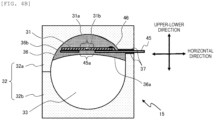
FIGS. 4A and4B are diagrams showing an example of the structure of thepressure sensor 15 according to the present embodiment.FIG. 4A is an exploded perspective view of thepressure sensor 15.FIG. 4B is a cross-sectional view of thepressure sensor 15 taken along a plane orthogonal to an extending direction of a flow channel. - The
pressure sensor 15 includes thesensor chip 31 formed of the thin-film semiconductor, thehousing 32 accommodating thesensor chip 31, and astrain transmission material 36 provided inside thehousing 32, and a fluid flowing through aflow channel 33 is the measurement target. Thefluid flow channel 33 is a space formed inside thehousing 32. Thestrain gauge portion 31b as a strain detection unit is provided on the surface of the center portion of thesensor chip 31. The fluid flowing through theflow channel 33 as the measurement target is, for example, thesystem water 21. - The cross section shown in
FIG. 4B is a cross section taken along a plane (plane along the normal direction of the sensor chip 31) passing through thestrain gauge portion 31b and orthogonal to a direction in which the fluid flows through theflow channel 33. - Here, the normal direction of the
sensor chip 31 is defined as a "upper-lower direction", an extending direction of the flow channel 33 (the direction in which the fluid flows through the flow channel 33) is defined as a "flow channel direction", and a direction orthogonal to the upper-lower direction and the flow channel direction is defined as a "horizontal direction". - The
housing 32 includes anupper housing 32a and alower housing 32b positioned below theupper housing 32a, and includes, in thehousing 32, theflow channel 33 through which thesystem water 21 flows. Theupper housing 32a and thelower housing 32b are in contact with each other, and acontact surface 32c of theupper housing 32a and thelower housing 32b is sealed with a sealing member, so that thesystem water 21 does not leak from thehousing 32. For example, an O-ring or a sealing agent can be used as the sealing member. It should be noted that it is not always necessary for thehousing 32 to be constituted by two parts (theupper housing 32a and thelower housing 32b), and for example, thehousing 32 may be configured with one part, for example, by insert molding, or may be configured with three or more parts. - Screw portions (not shown) are provided at both ends of the
flow channel 33 in the flow channel direction. Theflow channel 33 can be connected to thepipe 8 of thedispensing device 1 via a joint by the screw portion. - The
strain transmission material 36 is fixed to an inner surface of the housing 32 (that is, a wall surface of the flow channel 33). A surface of thestrain transmission material 36 fixed to the inner surface of thehousing 32 is referred to as abonding surface 36b. When coming into contact with thesystem water 21 flowing through theflow channel 33, thestrain transmission material 36 is compressed by a pressure of thesystem water 21. A surface of thestrain transmission material 36 in contact with thesystem water 21 is referred to as a pressure-receivingsurface 36a. The pressure-receivingsurface 36a is a surface that is in contact with the space that is thefluid flow channel 33 and receives the pressure of thesystem water 21. Thebonding surface 36b is positioned at an opposite side of thestrain transmission material 36 from the pressure-receivingsurface 36a. Thestrain transmission material 36 can be made of a flexible elastic body, and can be made of a gel substance such as silicone gel. - The
pressure sensor 15 may include alead frame 45 electrically connected to thesensor chip 31. Thelead frame 45 is provided to be in contact with thesensor chip 31 in the upper-lower direction. Note that a upper-lower relationship between positions of thelead frame 45 and thesensor chip 31 can be freely determined, and either thelead frame 45 or thesensor chip 31 may be provided on an upper side (position close to the inner surface of thehousing 32 inFIG. 4B ). In the present embodiment, as an example, thesensor chip 31 is positioned on the upper side of thelead frame 45. - The
entire sensor chip 31 and a part of thelead frame 45 are embedded inside thestrain transmission material 36. - The
lead frame 45 includes anaperture 45a which is an opening (hole) penetrating thelead frame 45. Theaperture 45a opens in a range facing a portion of thesensor chip 31 including thestrain gauge portion 31b. That is, a portion of thelead frame 45 facing thestrain gauge portion 31b of thesensor chip 31 and a peripheral portion thereof is opened as theaperture 45a. - A portion of the
sensor chip 31 released by theaperture 45a (that is, a portion facing theaperture 45a) is adiaphragm portion 31a which is a deformation portion. Thelead frame 45 includes theaperture 45a, so that the strain generated by the compression of thestrain transmission material 36 is transmitted from thestrain transmission material 36 to thediaphragm portion 31a of thesensor chip 31, and thediaphragm portion 31a is bent and deformed. Thesensor chip 31 measures the pressure of thesystem water 21 flowing through theflow channel 33 inside thehousing 32 by measuring the strain with thestrain gauge portion 31b. - The
lead frame 45 is provided to extract an output from thesensor chip 31. A lead portion of thelead frame 45 is electrically connected to an electrode portion of thesensor chip 31 by abonding wire 46. A part of thelead frame 45 protrudes to an outside of thehousing 32, and the lead portion extends to a protruding portion. A sealingmember 37 seals between thelead frame 45 and thehousing 32. Any member can be used as the sealingmember 37, for example, thestrain transmission material 36 may be used as the sealingmember 37, an O-ring may be used, or a gasket or the like formed on thelead frame 45 may be used. - The
sensor chip 31 can be electrically connected to the outside of thehousing 32 by the lead portion of thelead frame 45. In the pressure sensor in the related art, when thesensor chip 31 is provided inside thehousing 32, it is difficult to electrically connect thesensor chip 31 to the outside of thehousing 32 by connecting a wire to thesensor chip 31. In thepressure sensor 15 according to the present embodiment, thesensor chip 31 can be electrically connected to the outside of thehousing 32 by thelead frame 45 electrically connected to thesensor chip 31. - The characteristics of the
pressure sensor 15 according to the present embodiment are that thestrain transmission material 36 includes the pressure-receivingsurface 36a that is in contact with thefluid flow channel 33 and receives the pressure from the fluid, and thebonding surface 36b that is positioned at the opposite side of thestrain transmission material 36 from the pressure-receivingsurface 36a and is in contact with the inner surface of the housing 32 (that is, the wall surface of the flow channel 33), and that theentire sensor chip 31 is embedded in thestrain transmission material 36. - Due to the characteristic that the
bonding surface 36b is positioned at the opposite side of thestrain transmission material 36 from the pressure-receivingsurface 36a, in thestrain transmission material 36, when the pressure-receivingsurface 36a receives the pressure from the fluid, a compressive stress is generated in thebonding surface 36b. That is, in thestrain transmission material 36, when the pressure-receivingsurface 36a receives the pressure from the fluid, a force is generated in a direction in which thebonding surface 36b is pressed against thehousing 32, and thus in principle, thebonding surface 36b does not peel off from thehousing 32. - Due to the characteristic that the
entire sensor chip 31 is embedded in thestrain transmission material 36, a boundary surface between thesensor chip 31 and thestrain transmission material 36 is not exposed to thesystem water 21 or the outside air. Therefore, the decrease in the bonding force between thesensor chip 31 and thestrain transmission material 36 due to the humidity of thesystem water 21 or the outside air does not occur. - Accordingly, even when receiving the pressure from the fluid, the
pressure sensor 15 according to the present embodiment can prevent a decrease in sensitivity of thesensor chip 31 due to the peeling off and a leakage of the fluid from a portion to which thesensor chip 31 is bonded. -
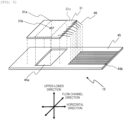
FIG. 5 is an exploded perspective view showing only thesensor chip 31, thebonding wire 46, and thelead frame 45 in thepressure sensor 15 according to the present embodiment. Anelectrode portion 31c of thesensor chip 31 is electrically connected to alead portion 45b of thelead frame 45 by thebonding wire 46. - The
aperture 45a provided in thelead frame 45 preferably has a shape having a longitudinal direction and a lateral direction, for example, a rectangular shape, an elliptical shape, or a rounded rectangular shape.FIG. 5 shows, as an example, theaperture 45a having the rectangular shape in which the longitudinal direction is the flow channel direction and the lateral direction is the horizontal direction. - The
diaphragm portion 31a of thesensor chip 31 is a portion of thesensor chip 31 that is released by theaperture 45a. For this reason, a shape of thediaphragm portion 31a is determined according to the shape of theaperture 45a, and is preferably a shape having the longitudinal direction and the lateral direction, for example, a rectangular shape, an elliptical shape, or a rounded rectangular shape. - When the
diaphragm portion 31a having the longitudinal direction and the lateral direction is deformed by receiving the pressure from thesystem water 21, a difference in a magnitude occurs between strain in the longitudinal direction and strain in the lateral direction in thestrain gauge portion 31b. - Where the
diaphragm portion 31a has the shape having the longitudinal direction and the lateral direction, it is preferable to use, as thesensor chip 31, a sensor chip that detects the respective strain in the longitudinal direction and the lateral direction of thestrain gauge portion 31b and outputs a difference in the strain therebetween. By using such asensor chip 31 capable of detecting anisotropy of the strain, thepressure sensor 15 can improve pressure detection sensitivity. An existing sensor chip can be used as such asensor chip 31. - In addition, when such a
sensor chip 31 is used, it is possible to reduce an influence of thermal strain that generates isotropic strain, that is, an influence of a temperature change. Accordingly, thepressure sensor 15 can reduce a change in output characteristics due to the temperature change. - It is preferable that the
strain transmission material 36 is made of a material having rigidity sufficiently smaller than rigidity of thehousing 32. In general, thehousing 32 is made of a material having sufficiently high rigidity, so that deformation due to the pressure of thesystem water 21 is sufficiently small. Thestrain transmission material 36 has rigidity sufficiently smaller than that of thehousing 32, so that only thestrain transmission material 36 is efficiently deformed due to a water pressure of thesystem water 21. Accordingly, thepressure sensor 15 can improve the pressure detection sensitivity. - A pressure sensor according to
Embodiment 2 of the invention will be described with reference toFIG. 6 . Thepressure sensor 15 according to the present embodiment has the same configuration as thepressure sensor 15 according toEmbodiment 1, but is different from thepressure sensor 15 according toEmbodiment 1 in that thesensor chip 31 includes a cap member. Hereinafter, thepressure sensor 15 according to the present embodiment will be described mainly with respect to the differences from thepressure sensor 15 according toEmbodiment 1. -
FIG. 6 is an exploded perspective view showing only thesensor chip 31, thebonding wire 46, thelead frame 45, and acap member 34 in thepressure sensor 15 according to the present embodiment. - The
cap member 34 is a member that is provided on the surface of thesensor chip 31 and covers and protects thestrain gauge portion 31b. Thecap member 34 is provided on the surface of thesensor chip 31 opposite a surface in contact with thelead frame 45 in the upper-lower direction, and is embedded in thestrain transmission material 36. Thecap member 34 may be made of, for example, silicon, and is bonded to thesensor chip 31 using an adhesive member such as a thermosetting adhesive. - The
cap member 34 includes acavity 34a. Thecavity 34a is a recess provided in a surface of thecap member 34 in contact with thesensor chip 31 and surrounding a periphery of thestrain gauge portion 31b. A portion of thesensor chip 31 facing thecavity 34a is deformable, and the deformable portion functions as thediaphragm portion 31a. Thecavity 34a preferably has a shape having the longitudinal direction and the lateral direction, for example, a rectangular shape, an elliptical shape, or a rounded rectangular shape.FIG. 6 shows, as an example, thecavity 34a having the elliptical shape (oval) in which the longitudinal direction is the flow channel direction and the lateral direction is the horizontal direction. - An outline of the
cavity 34a when thecavity 34a is projected onto thesensor chip 31 is referred to as an outershape projection line 51 of thecavity 34a. An outline of theaperture 45a when theaperture 45a is projected onto thesensor chip 31 is referred to as an outershape projection line 50 of theaperture 45a. An outline of thecap member 34 when thecap member 34 is projected onto thesensor chip 31 is referred to as an outershape projection line 52 of thecap member 34. In thepressure sensor 15 according to the present embodiment, the outershape projection line 51 of thecavity 34a is positioned closer to astrain gauge portion 31b side (inside) than the outershape projection line 50 of theaperture 45a, and the outershape projection line 52 of thecap member 34 is positioned more inward than theoutline 53 of thesensor chip 31. - The
sensor chip 31 included in thepressure sensor 15 according to the present embodiment is small, and is generally manufactured by using a semiconductor process to dice a sensor chip formed in a lattice shape on a silicon wafer into a rectangular shape. Since the outershape projection line 52 of thecap member 34 is positioned more inward than theoutline 53 of thesensor chip 31, it is possible to adopt a manufacturing method in which thecap member 34 is formed by a semiconductor process on the wafer on which the sensor chip is formed and then is diced. Accordingly, an external dimension and an arrangement position of thecap member 34 can be determined with high accuracy using the semiconductor process. - The outer
shape projection line 51 of thecavity 34a is positioned more inward than the outershape projection line 50 of theaperture 45a, so that the shape of thediaphragm portion 31a is determined by the outershape projection line 51 of thecavity 34a. Thecap member 34 can be manufactured with higher accuracy by the semiconductor process. Therefore, in thepressure sensor 15 according to the present embodiment, a manufacturing variation of the shape of thediaphragm portion 31a determined by the shape of thecavity 34a of thecap member 34 can be extremely reduced. Accordingly, the variation in the sensitivity of thesensor chip 31 due to the variation in the shape of thediaphragm portion 31a can also be reduced. - The
pressure sensor 15 according to the present embodiment has an effect of reducing variations in the sensitivity of thesensor chip 31 in addition to the effect of thepressure sensor 15 according toEmbodiment 1. - The invention is not limited to the above-described embodiments and may include various modifications. For example, the embodiments have been described in detail to facilitate understanding of the invention, and the invention is not necessarily limited to those including all configurations described above. A part of configurations of one embodiment can be replaced with a configuration of another embodiment. A configuration of another embodiment can be added to a configuration of one embodiment. A part of a configuration in each embodiment may be deleted, or may be added with or replaced with another configuration.
-
- 1: dispensing device
- 2: nozzle
- 4: syringe pump
- 5: solenoid valve
- 6: gear pump
- 7: tank
- 8: pipe
- 9: container
- 10: plunger
- 11: ball screw
- 12: drive motor
- 13: sample dispensing mechanism
- 14: control unit
- 15: pressure sensor
- 15a: pressure sensor of related art
- 16: arm
- 21: system water
- 22: liquid
- 23: dividing air
- 31: sensor chip
- 31a: diaphragm portion
- 31b: strain gauge portion
- 31c: electrode portion
- 32: housing
- 32a: upper housing
- 32b: lower housing
- 32c: contact surface between upper housing and lower housing
- 33: flow channel
- 34: cap member
- 34a: cavity
- 35: flow channel
- 36: strain transmission material
- 36a: pressure-receiving surface
- 36b: bonding surface
- 37: sealing member
- 40: bonding agent
- 45: lead frame
- 45a: aperture
- 45b: lead portion
- 46: bonding wire
- 50: outer shape projection line of aperture
- 51: outer shape projection line of cavity
- 52: outer shape projection line of cap member
- 53: outline of sensor chip
Claims (5)
- A pressure sensor comprising:a housing having therein a space serving as a fluid flow channel;a sensor chip including a strain detection unit and formed of a thin-film semiconductor; anda strain transmission material provided inside the housing, whereinthe strain transmission material includes a pressure-receiving surface in contact with the space, and a bonding surface positioned at an opposite side of the strain transmission material from the pressure-receiving surface and fixed to an inner surface of the housing, andthe entire sensor chip is embedded inside the strain transmission material.
- The pressure sensor according to claim 1, wherein
the strain transmission material has rigidity smaller than that of the housing. - The pressure sensor according to claim 1, further comprising:a lead frame provided in contact with the sensor chip and electrically connected to an electrode of the sensor chip, whereinthe lead frame includes an opening that opens in a range facing a portion of the sensor chip including the strain detection unit.
- The pressure sensor according to claim 3, further comprising:a cap member provided on a surface of the sensor chip opposite a surface in contact with the lead frame, whereinthe cap member includes a recess having a shape having a longitudinal direction and a lateral direction and surrounding a periphery of the strain detection unit on a surface in contact with the sensor chip, andwhen the recess, the opening, and the cap member are projected onto the sensor chip, an outline of the projected recess is positioned more inward than an outline of the projected opening, and an outline of the projected cap member is positioned more inward than an outline of the projected sensor chip.
- The pressure sensor according to claim 3, wherein
a part of the lead frame is embedded in the strain transmission material, and another part of the lead frame protrudes to an outside of the housing.
Applications Claiming Priority (2)
| Application Number | Priority Date | Filing Date | Title |
|---|---|---|---|
| JP2022088556A JP7817080B2 (en) | 2022-05-31 | 2022-05-31 | Pressure Sensor |
| PCT/JP2023/014233 WO2023233819A1 (en) | 2022-05-31 | 2023-04-06 | Pressure sensor |
Publications (2)
| Publication Number | Publication Date |
|---|---|
| EP4534968A1 true EP4534968A1 (en) | 2025-04-09 |
| EP4534968A4 EP4534968A4 (en) | 2026-04-22 |
Family
ID=89026184
Family Applications (1)
| Application Number | Title | Priority Date | Filing Date |
|---|---|---|---|
| EP23815581.6A Pending EP4534968A4 (en) | 2022-05-31 | 2023-04-06 | PRESSURE SENSOR |
Country Status (5)
| Country | Link |
|---|---|
| US (1) | US20250283770A1 (en) |
| EP (1) | EP4534968A4 (en) |
| JP (1) | JP7817080B2 (en) |
| CN (1) | CN119173748A (en) |
| WO (1) | WO2023233819A1 (en) |
Families Citing this family (2)
| Publication number | Priority date | Publication date | Assignee | Title |
|---|---|---|---|---|
| WO2025079724A1 (en) | 2023-10-11 | 2025-04-17 | 日本製鉄株式会社 | Steel material and pressure vessel |
| CN117800113B (en) * | 2024-02-27 | 2024-05-28 | 中央储备粮三明直属库有限公司 | Intelligent bucket type lifting bin discharger |
Family Cites Families (8)
| Publication number | Priority date | Publication date | Assignee | Title |
|---|---|---|---|---|
| JP2771923B2 (en) * | 1992-06-02 | 1998-07-02 | 三菱電機株式会社 | Semiconductor pressure sensor |
| US5581038A (en) * | 1994-04-04 | 1996-12-03 | Sentir, Inc. | Pressure measurement apparatus having a reverse mounted transducer and overpressure guard |
| JPH09138172A (en) * | 1995-11-14 | 1997-05-27 | Fujikura Ltd | Semiconductor pressure sensor and method of manufacturing the same |
| DE19626084C2 (en) * | 1996-06-28 | 2003-04-17 | Infineon Technologies Ag | Pressure sensor device for mounting on the assembly surface of a printed circuit board |
| US6394986B1 (en) * | 1999-11-06 | 2002-05-28 | Millar Instruments, Inc. | Pressure sensing module for a catheter pressure transducer |
| JP6862964B2 (en) * | 2017-03-17 | 2021-04-21 | 富士電機株式会社 | Manufacturing method of semiconductor pressure sensor device and semiconductor pressure sensor device |
| JP7251510B2 (en) * | 2020-03-31 | 2023-04-04 | 株式会社デンソー | Pressure sensor for evaporative fuel leak inspection device |
| DE102020206027B4 (en) * | 2020-05-13 | 2024-10-02 | Festo Se & Co. Kg | Pressure sensor device and fluid guide device equipped therewith |
-
2022
- 2022-05-31 JP JP2022088556A patent/JP7817080B2/en active Active
-
2023
- 2023-04-06 CN CN202380039571.3A patent/CN119173748A/en active Pending
- 2023-04-06 WO PCT/JP2023/014233 patent/WO2023233819A1/en not_active Ceased
- 2023-04-06 US US18/859,386 patent/US20250283770A1/en active Pending
- 2023-04-06 EP EP23815581.6A patent/EP4534968A4/en active Pending
Also Published As
| Publication number | Publication date |
|---|---|
| WO2023233819A1 (en) | 2023-12-07 |
| EP4534968A4 (en) | 2026-04-22 |
| CN119173748A (en) | 2024-12-20 |
| JP7817080B2 (en) | 2026-02-18 |
| US20250283770A1 (en) | 2025-09-11 |
| JP2023176326A (en) | 2023-12-13 |
Similar Documents
| Publication | Publication Date | Title |
|---|---|---|
| US20250283770A1 (en) | Pressure sensor | |
| JP7274526B2 (en) | System and method for measuring fluid flow pressure | |
| US8104352B2 (en) | Pressure measurement unit for determining fluid pressure within medical disposables | |
| US6649046B2 (en) | Device for measuring negative pressures in an extracorporeal blood circuit | |
| US6820490B2 (en) | Systems and methods for measuring pressure | |
| US11215577B2 (en) | Test system for analyzing a sample of a bodily fluid | |
| US4683894A (en) | Disposable physiological pressure sensing system | |
| BR112015001962B1 (en) | FLUID RESERVOIR AND FLUID PRESSURE MEASUREMENT UNIT TO MEASURE A FLUID PRESSURE IN THE SAME | |
| WO2017166696A1 (en) | Blood gas analyzer and blood gas biochemical test card thereof | |
| CN110657925B (en) | Method for testing hermetic seal of package | |
| US20240230441A9 (en) | Pressure Sensor Module and Dispensing Device | |
| US11000646B2 (en) | Infusion device for acting onto a tube set | |
| WO2017166693A1 (en) | Blood gas analyzer and blood gas biochemical test card thereof | |
| EA023071B1 (en) | Apparatus for treating a medical liquid, and method for checking the leaktightness of the apparatus | |
| EP4443126A1 (en) | Pressure sensor module and dispensing device having pressure sensor module | |
| KR20020082315A (en) | Device for injecting liquid transmitting pressure of pressure gage and sensor protector, injecting method using this and diapram housing equipped with nipple | |
| CN116159606A (en) | Microfluidic detection system for refrigerator and refrigerator | |
| CN1323983A (en) | Leakage amount detector | |
| WO2017166692A1 (en) | Blood gas analyzer and blood gas biochemical test card thereof | |
| JP3373453B2 (en) | Automatic dispensing device | |
| JP7592191B2 (en) | Pressure sensor and dispensing device | |
| CN221903671U (en) | Trace hemostix convenient for detecting and sampling | |
| CN114930164B (en) | Solid ion selective electrode | |
| EP4394342A1 (en) | Pressure sensor | |
| KR20130063935A (en) | Device for storing reagent, and method discharging reagent of the said device |
Legal Events
| Date | Code | Title | Description |
|---|---|---|---|
| STAA | Information on the status of an ep patent application or granted ep patent |
Free format text: STATUS: THE INTERNATIONAL PUBLICATION HAS BEEN MADE |
|
| PUAI | Public reference made under article 153(3) epc to a published international application that has entered the european phase |
Free format text: ORIGINAL CODE: 0009012 |
|
| STAA | Information on the status of an ep patent application or granted ep patent |
Free format text: STATUS: REQUEST FOR EXAMINATION WAS MADE |
|
| 17P | Request for examination filed |
Effective date: 20241022 |
|
| AK | Designated contracting states |
Kind code of ref document: A1 Designated state(s): AL AT BE BG CH CY CZ DE DK EE ES FI FR GB GR HR HU IE IS IT LI LT LU LV MC ME MK MT NL NO PL PT RO RS SE SI SK SM TR |
|
| DAV | Request for validation of the european patent (deleted) | ||
| DAX | Request for extension of the european patent (deleted) | ||
| A4 | Supplementary search report drawn up and despatched |
Effective date: 20260319 |
|
| RIC1 | Information provided on ipc code assigned before grant |
Ipc: G01L 9/00 20060101AFI20260313BHEP Ipc: G01L 7/00 20060101ALI20260313BHEP Ipc: G01L 19/06 20060101ALI20260313BHEP Ipc: G01L 19/14 20060101ALI20260313BHEP Ipc: G01L 19/00 20060101ALI20260313BHEP |