EP4534941A1 - Circulation device for two-phase cooling system and refrigerant circulation method in circulation device for two-phase cooling system - Google Patents
Circulation device for two-phase cooling system and refrigerant circulation method in circulation device for two-phase cooling system Download PDFInfo
- Publication number
- EP4534941A1 EP4534941A1 EP23811640.4A EP23811640A EP4534941A1 EP 4534941 A1 EP4534941 A1 EP 4534941A1 EP 23811640 A EP23811640 A EP 23811640A EP 4534941 A1 EP4534941 A1 EP 4534941A1
- Authority
- EP
- European Patent Office
- Prior art keywords
- refrigerant
- evaporator
- circulation device
- cooling system
- bypass line
- Prior art date
- Legal status (The legal status is an assumption and is not a legal conclusion. Google has not performed a legal analysis and makes no representation as to the accuracy of the status listed.)
- Pending
Links
Images





Classifications
-
- F—MECHANICAL ENGINEERING; LIGHTING; HEATING; WEAPONS; BLASTING
- F25—REFRIGERATION OR COOLING; COMBINED HEATING AND REFRIGERATION SYSTEMS; HEAT PUMP SYSTEMS; MANUFACTURE OR STORAGE OF ICE; LIQUEFACTION SOLIDIFICATION OF GASES
- F25B—REFRIGERATION MACHINES, PLANTS OR SYSTEMS; COMBINED HEATING AND REFRIGERATION SYSTEMS; HEAT PUMP SYSTEMS
- F25B13/00—Compression machines, plants or systems, with reversible cycle
-
- F—MECHANICAL ENGINEERING; LIGHTING; HEATING; WEAPONS; BLASTING
- F28—HEAT EXCHANGE IN GENERAL
- F28D—HEAT-EXCHANGE APPARATUS, NOT PROVIDED FOR IN ANOTHER SUBCLASS, IN WHICH THE HEAT-EXCHANGE MEDIA DO NOT COME INTO DIRECT CONTACT
- F28D15/00—Heat-exchange apparatus with the intermediate heat-transfer medium in closed tubes passing into or through the conduit walls ; Heat-exchange apparatus employing intermediate heat-transfer medium or bodies
- F28D15/02—Heat-exchange apparatus with the intermediate heat-transfer medium in closed tubes passing into or through the conduit walls ; Heat-exchange apparatus employing intermediate heat-transfer medium or bodies in which the medium condenses and evaporates, e.g. heat pipes
- F28D15/06—Control arrangements therefor
-
- F—MECHANICAL ENGINEERING; LIGHTING; HEATING; WEAPONS; BLASTING
- F25—REFRIGERATION OR COOLING; COMBINED HEATING AND REFRIGERATION SYSTEMS; HEAT PUMP SYSTEMS; MANUFACTURE OR STORAGE OF ICE; LIQUEFACTION SOLIDIFICATION OF GASES
- F25B—REFRIGERATION MACHINES, PLANTS OR SYSTEMS; COMBINED HEATING AND REFRIGERATION SYSTEMS; HEAT PUMP SYSTEMS
- F25B23/00—Machines, plants or systems, with a single mode of operation not covered by groups F25B1/00 - F25B21/00, e.g. using selective radiation effect
- F25B23/006—Machines, plants or systems, with a single mode of operation not covered by groups F25B1/00 - F25B21/00, e.g. using selective radiation effect boiling cooling systems
-
- F—MECHANICAL ENGINEERING; LIGHTING; HEATING; WEAPONS; BLASTING
- F25—REFRIGERATION OR COOLING; COMBINED HEATING AND REFRIGERATION SYSTEMS; HEAT PUMP SYSTEMS; MANUFACTURE OR STORAGE OF ICE; LIQUEFACTION SOLIDIFICATION OF GASES
- F25B—REFRIGERATION MACHINES, PLANTS OR SYSTEMS; COMBINED HEATING AND REFRIGERATION SYSTEMS; HEAT PUMP SYSTEMS
- F25B25/00—Machines, plants or systems, using a combination of modes of operation covered by two or more of the groups F25B1/00 - F25B23/00
- F25B25/005—Machines, plants or systems, using a combination of modes of operation covered by two or more of the groups F25B1/00 - F25B23/00 using primary and secondary systems
-
- F—MECHANICAL ENGINEERING; LIGHTING; HEATING; WEAPONS; BLASTING
- F25—REFRIGERATION OR COOLING; COMBINED HEATING AND REFRIGERATION SYSTEMS; HEAT PUMP SYSTEMS; MANUFACTURE OR STORAGE OF ICE; LIQUEFACTION SOLIDIFICATION OF GASES
- F25B—REFRIGERATION MACHINES, PLANTS OR SYSTEMS; COMBINED HEATING AND REFRIGERATION SYSTEMS; HEAT PUMP SYSTEMS
- F25B39/00—Evaporators; Condensers
- F25B39/02—Evaporators
-
- F—MECHANICAL ENGINEERING; LIGHTING; HEATING; WEAPONS; BLASTING
- F25—REFRIGERATION OR COOLING; COMBINED HEATING AND REFRIGERATION SYSTEMS; HEAT PUMP SYSTEMS; MANUFACTURE OR STORAGE OF ICE; LIQUEFACTION SOLIDIFICATION OF GASES
- F25B—REFRIGERATION MACHINES, PLANTS OR SYSTEMS; COMBINED HEATING AND REFRIGERATION SYSTEMS; HEAT PUMP SYSTEMS
- F25B39/00—Evaporators; Condensers
- F25B39/04—Condensers
-
- F—MECHANICAL ENGINEERING; LIGHTING; HEATING; WEAPONS; BLASTING
- F25—REFRIGERATION OR COOLING; COMBINED HEATING AND REFRIGERATION SYSTEMS; HEAT PUMP SYSTEMS; MANUFACTURE OR STORAGE OF ICE; LIQUEFACTION SOLIDIFICATION OF GASES
- F25B—REFRIGERATION MACHINES, PLANTS OR SYSTEMS; COMBINED HEATING AND REFRIGERATION SYSTEMS; HEAT PUMP SYSTEMS
- F25B41/00—Fluid-circulation arrangements
- F25B41/20—Disposition of valves, e.g. of on-off valves or flow control valves
- F25B41/24—Arrangement of shut-off valves for disconnecting a part of the refrigerant cycle, e.g. an outdoor part
-
- F—MECHANICAL ENGINEERING; LIGHTING; HEATING; WEAPONS; BLASTING
- F25—REFRIGERATION OR COOLING; COMBINED HEATING AND REFRIGERATION SYSTEMS; HEAT PUMP SYSTEMS; MANUFACTURE OR STORAGE OF ICE; LIQUEFACTION SOLIDIFICATION OF GASES
- F25B—REFRIGERATION MACHINES, PLANTS OR SYSTEMS; COMBINED HEATING AND REFRIGERATION SYSTEMS; HEAT PUMP SYSTEMS
- F25B49/00—Arrangement or mounting of control or safety devices
- F25B49/02—Arrangement or mounting of control or safety devices for compression type machines, plants or systems
-
- F—MECHANICAL ENGINEERING; LIGHTING; HEATING; WEAPONS; BLASTING
- F28—HEAT EXCHANGE IN GENERAL
- F28D—HEAT-EXCHANGE APPARATUS, NOT PROVIDED FOR IN ANOTHER SUBCLASS, IN WHICH THE HEAT-EXCHANGE MEDIA DO NOT COME INTO DIRECT CONTACT
- F28D15/00—Heat-exchange apparatus with the intermediate heat-transfer medium in closed tubes passing into or through the conduit walls ; Heat-exchange apparatus employing intermediate heat-transfer medium or bodies
- F28D15/02—Heat-exchange apparatus with the intermediate heat-transfer medium in closed tubes passing into or through the conduit walls ; Heat-exchange apparatus employing intermediate heat-transfer medium or bodies in which the medium condenses and evaporates, e.g. heat pipes
-
- F—MECHANICAL ENGINEERING; LIGHTING; HEATING; WEAPONS; BLASTING
- F28—HEAT EXCHANGE IN GENERAL
- F28D—HEAT-EXCHANGE APPARATUS, NOT PROVIDED FOR IN ANOTHER SUBCLASS, IN WHICH THE HEAT-EXCHANGE MEDIA DO NOT COME INTO DIRECT CONTACT
- F28D15/00—Heat-exchange apparatus with the intermediate heat-transfer medium in closed tubes passing into or through the conduit walls ; Heat-exchange apparatus employing intermediate heat-transfer medium or bodies
- F28D15/02—Heat-exchange apparatus with the intermediate heat-transfer medium in closed tubes passing into or through the conduit walls ; Heat-exchange apparatus employing intermediate heat-transfer medium or bodies in which the medium condenses and evaporates, e.g. heat pipes
- F28D15/0266—Heat-exchange apparatus with the intermediate heat-transfer medium in closed tubes passing into or through the conduit walls ; Heat-exchange apparatus employing intermediate heat-transfer medium or bodies in which the medium condenses and evaporates, e.g. heat pipes with separate evaporating and condensing chambers connected by at least one conduit; Loop-type heat pipes; with multiple or common evaporating or condensing chambers
-
- H—ELECTRICITY
- H05—ELECTRIC TECHNIQUES NOT OTHERWISE PROVIDED FOR
- H05K—PRINTED CIRCUITS; CASINGS OR CONSTRUCTIONAL DETAILS OF ELECTRIC APPARATUS; MANUFACTURE OF ASSEMBLAGES OF ELECTRICAL COMPONENTS
- H05K7/00—Constructional details common to different types of electric apparatus
- H05K7/20—Modifications to facilitate cooling, ventilating, or heating
- H05K7/2029—Modifications to facilitate cooling, ventilating, or heating using a liquid coolant with phase change in electronic enclosures
- H05K7/20327—Accessories for moving fluid, for connecting fluid conduits, for distributing fluid or for preventing leakage, e.g. pumps, tanks or manifolds
-
- H—ELECTRICITY
- H05—ELECTRIC TECHNIQUES NOT OTHERWISE PROVIDED FOR
- H05K—PRINTED CIRCUITS; CASINGS OR CONSTRUCTIONAL DETAILS OF ELECTRIC APPARATUS; MANUFACTURE OF ASSEMBLAGES OF ELECTRICAL COMPONENTS
- H05K7/00—Constructional details common to different types of electric apparatus
- H05K7/20—Modifications to facilitate cooling, ventilating, or heating
- H05K7/2029—Modifications to facilitate cooling, ventilating, or heating using a liquid coolant with phase change in electronic enclosures
- H05K7/20336—Heat pipes, e.g. wicks or capillary pumps
-
- F—MECHANICAL ENGINEERING; LIGHTING; HEATING; WEAPONS; BLASTING
- F25—REFRIGERATION OR COOLING; COMBINED HEATING AND REFRIGERATION SYSTEMS; HEAT PUMP SYSTEMS; MANUFACTURE OR STORAGE OF ICE; LIQUEFACTION SOLIDIFICATION OF GASES
- F25B—REFRIGERATION MACHINES, PLANTS OR SYSTEMS; COMBINED HEATING AND REFRIGERATION SYSTEMS; HEAT PUMP SYSTEMS
- F25B2339/00—Details of evaporators; Details of condensers
- F25B2339/02—Details of evaporators
-
- F—MECHANICAL ENGINEERING; LIGHTING; HEATING; WEAPONS; BLASTING
- F25—REFRIGERATION OR COOLING; COMBINED HEATING AND REFRIGERATION SYSTEMS; HEAT PUMP SYSTEMS; MANUFACTURE OR STORAGE OF ICE; LIQUEFACTION SOLIDIFICATION OF GASES
- F25B—REFRIGERATION MACHINES, PLANTS OR SYSTEMS; COMBINED HEATING AND REFRIGERATION SYSTEMS; HEAT PUMP SYSTEMS
- F25B2400/00—Component parts or details not otherwise provided for in this subclass
- F25B2400/04—Refrigeration circuit bypassing means
- F25B2400/0409—Refrigeration circuit bypassing means for evaporators
-
- F—MECHANICAL ENGINEERING; LIGHTING; HEATING; WEAPONS; BLASTING
- F25—REFRIGERATION OR COOLING; COMBINED HEATING AND REFRIGERATION SYSTEMS; HEAT PUMP SYSTEMS; MANUFACTURE OR STORAGE OF ICE; LIQUEFACTION SOLIDIFICATION OF GASES
- F25B—REFRIGERATION MACHINES, PLANTS OR SYSTEMS; COMBINED HEATING AND REFRIGERATION SYSTEMS; HEAT PUMP SYSTEMS
- F25B2600/00—Control issues
- F25B2600/25—Control of valves
- F25B2600/2501—Bypass valves
-
- F—MECHANICAL ENGINEERING; LIGHTING; HEATING; WEAPONS; BLASTING
- F25—REFRIGERATION OR COOLING; COMBINED HEATING AND REFRIGERATION SYSTEMS; HEAT PUMP SYSTEMS; MANUFACTURE OR STORAGE OF ICE; LIQUEFACTION SOLIDIFICATION OF GASES
- F25B—REFRIGERATION MACHINES, PLANTS OR SYSTEMS; COMBINED HEATING AND REFRIGERATION SYSTEMS; HEAT PUMP SYSTEMS
- F25B2600/00—Control issues
- F25B2600/25—Control of valves
- F25B2600/2519—On-off valves
-
- F—MECHANICAL ENGINEERING; LIGHTING; HEATING; WEAPONS; BLASTING
- F25—REFRIGERATION OR COOLING; COMBINED HEATING AND REFRIGERATION SYSTEMS; HEAT PUMP SYSTEMS; MANUFACTURE OR STORAGE OF ICE; LIQUEFACTION SOLIDIFICATION OF GASES
- F25B—REFRIGERATION MACHINES, PLANTS OR SYSTEMS; COMBINED HEATING AND REFRIGERATION SYSTEMS; HEAT PUMP SYSTEMS
- F25B2700/00—Sensing or detecting of parameters; Sensors therefor
- F25B2700/04—Refrigerant level
Definitions
- a two-phase cooling system in which a refrigerant is circulated by connecting a removable evaporator to a connection is known.
- a circulation device for such a two-phase cooling system is disclosed in Japanese Patent Laid-Open No. 2003-179375 , for example.
- 2003-179375 discloses that it is advantageous to connect a connection between an evaporative cold plate inlet and the liquid conduit, and a connection between an evaporative cold plate outlet and the vapor conduit by removable connection means. That is, Japanese Patent Laid-Open No. 2003-179375 discloses a cooling apparatus in which the evaporative cold plate (evaporator) is attachable to and detachable from a structure including the condenser, the vapor conduit, and the liquid conduit.
- the working fluid with an increased temperature circulates, and thus the cooled working fluid cannot be flowed into the evaporative cold plate. Therefore, immediately after the evaporative cold plate is reattached, the evaporative cold plate cannot immediately cool a target to be cooled. Therefore, it is desired to be able to flow a cooled, low-temperature working fluid (refrigerant) into the evaporative cold plate (evaporator) even immediately after the evaporative cold plate (evaporator) is removed and then reconnected, and to be able to immediately cool the target to be cooled by the evaporative cold plate (evaporator).
- refrigerant low-temperature working fluid
- the present invention is intended to solve at least one of the above problems.
- the present invention aims to provide a circulation device for a two-phase cooling system and a refrigerant circulation method in a circulation device for a two-phase cooling system in which a cooled, low-temperature refrigerant can be flowed into a removable evaporator even immediately after the evaporator is removed and then reconnected, and a target to be cooled can be immediately cooled by the evaporator.
- FIG. 1 shows the circulation device 100 for a two-phase cooling system with a removable evaporator 80 connected thereto.
- the circulation device 100 for a two-phase cooling system constitutes a two-phase cooling system 200 in which a refrigerant is circulated by connecting the removable evaporator 80 to the circulation device 100 for a two-phase cooling system.
- the term "with the removable evaporator 80 connected thereto" refers to a normal operating state in which the evaporator 80 is attached to the circulation device 100 for a two-phase cooling system and cools a heat source 81 (target to be cooled), for example.
- inlet side of the inlet connection 41 refers to the inlet side of the evaporator 80
- outlet side of the outlet connection 42 refers to the outlet side of the evaporator 80
- inlet side of the inlet side shut-off valve 51 refers to the inlet side of the evaporator 80
- outlet side of the outlet side shut-off valve 52 refers to the outlet side of the evaporator 80.
- a first end of the bypass line 75 is connected to the bifurcation 76 formed in the first refrigerant flow path 71, and a second end of the bypass line 75 is connected to the junction 77 formed in the second refrigerant flow path 72.
- upstream of the pump 10 refers to a portion upstream of the pump 10 and does not include the pump 10.
- downstream of the pump 10 refers to a portion downstream of the pump 10 and does not include the pump 10. The same applies to the terms “upstream of the condenser 20" and “downstream of the condenser 20", the terms “upstream of the reservoir 30" and “downstream of the reservoir 30”, and the term “upstream of the evaporator 80" and "downstream of the evaporator 80.
- the pump 10 takes in the liquid phase refrigerant 1 from the inlet of the pump 10 and discharges the liquid phase refrigerant 1 from the outlet of the pump 10.
- the pump 10 is a centrifugal pump.
- the pump 10 is not limited to a centrifugal pump.
- the pump 10 may be a mixed flow pump, an axial flow pump, or another known pump.
- the pump 10 may also be a positive displacement pump.
- the reservoir 30 stores the liquid refrigerant 1.
- the reservoir 30 separates bubbles (gas-phase refrigerant) contained in the gas-liquid mixed refrigerant 2 and stores the separated bubbles in an upper portion of the reservoir 30.
- the reservoir 30 is provided downstream of the condenser 20 in the third refrigerant flow path 73.
- the reservoir 30 allows the liquid refrigerant 1 to flow thereinto from the inlet of the reservoir 30 and allows the liquid refrigerant 1 to flow out from the outlet of the reservoir 30.
- the reservoir 30 sends the liquid refrigerant 1 to the pump 10 via the fourth refrigerant flow path 74.
- the heat source 81 is provided on one surface of the cold plate 82.
- the evaporator 80 and the heat source 81 are integrally formed.
- the refrigerant flow path 83 shown in FIG. 1 is a schematic view.
- the refrigerant flow path 83 may have a structure that is bent a plurality of times inside the evaporator 80 in order to perform efficient heat exchange.
- the refrigerant flow path 83 may be formed so as to split into a plurality of paths at the inlet, pass through the inside of the evaporator 80, and merge into one path at the outlet.
- the structure of the evaporator 80 is not particularly limited.
- the refrigerant is carbon dioxide.
- the refrigerant may be chlorofluorocarbon or ammonia, for example.
- FIG. 2 shows the circulation device 100 for a two-phase cooling system without the removable evaporator 80 connected thereto.
- the term "without the removable evaporator 80 connected thereto" refers to a state in which the evaporator 80 is removed from the circulation device 100 for a two-phase cooling system due to maintenance of the heat source 81 or the evaporator 80, for example.
- the inlet side shut-off valve 51 and the outlet side shut-off valve 52 are in a closed state.
- Refrigerant circulation in the circulation device 100 for a two-phase cooling system with the evaporator 80 connected to the inlet connection 41 and the outlet connection 42 is now described with reference to FIG. 1 .
- the inlet side shut-off valve 51 and the outlet side shut-off valve 52 are fully closed to prevent the liquid refrigerant 1 from flowing out from the inlet connection 41 and the gas-liquid mixed refrigerant 2 from flowing out from the outlet connection 42.
- the liquid refrigerant 1 flows into the bypass line 75 except for the refrigerant that flows between the bifurcation 76 and the inlet side shut-off valve 51.
- the liquid refrigerant 1 that flows in from the bypass line 75 flows through the second refrigerant flow path 72 and flows into the condenser 20.
- the liquid refrigerant 1 is pumped from the pump 10.
- the liquid refrigerant 1 flows through the first refrigerant flow path 71.
- the liquid refrigerant 1 flows into the bypass line 75.
- the liquid refrigerant 1 that has flowed into the bypass line 75 flows through the orifice 61 provided in the bypass line 75 and flows into the junction 77 of the second refrigerant flow path 72.
- the liquid refrigerant 1 that has flowed into the junction 77 flows through the second refrigerant flow path 72 and flows into the condenser 20, except for the refrigerant that flows between the junction 77 and the outlet side shut-off valve 52.
- the liquid refrigerant 1 that has flowed into the condenser 20 is cooled or maintained in a cooled state.
- the liquid refrigerant 1 flows from the condenser 20 through the third refrigerant flow path 73 into the reservoir 30.
- the refrigerant that has flowed into the reservoir 30 flows through the fourth refrigerant flow path 74 into the pump 10.
- the liquid refrigerant 1 can be circulated through the bypass line 75, and thus the liquid refrigerant 1 can be continuously cooled by the condenser 20. Therefore, even immediately after the removable evaporator 80 is removed from the inlet connection 41 and the outlet connection 42 and then reconnected, the cooled, low-temperature liquid refrigerant 1 can be flowed into the evaporator 80, and the heat source 81 can be immediately cooled by the evaporator 80.
- the refrigerant circulation method includes a step of circulating the refrigerant not through the inlet connection 41 and the outlet connection 42 but through the bypass line 75 operable to allow the refrigerant to flow therethrough when at least the evaporator 80 is not connected to the inlet connection 41 and the outlet connection 42, and a step of cooling the refrigerant that has flowed through the bypass line 75 into the condenser 20. Accordingly, even when the removable evaporator 80 is not connected to the inlet connection 41 and the outlet connection 42, the liquid refrigerant 1 can be circulated through the bypass line 75, and thus the liquid refrigerant 1 can be continuously cooled by the condenser 20.
- the cooled, low-temperature liquid refrigerant 1 can be flowed into the evaporator 80, and the heat source 81 can be immediately cooled by the evaporator 80.
- the circulation device 100 for a two-phase cooling system is configured as follows such that the following advantages are further obtained.
- the liquid phase refrigerant 1 can be circulated through the bypass line 75 in the normal operating state in which the evaporator 80 is connected to the inlet connection 41 and the outlet connection 42, the liquid refrigerant 1 can be circulated through the bypass line 75. Therefore, it is possible to reduce or prevent the occurrence of malfunctions in the circulation device 100 for a two-phase cooling system caused by an increase in pressure at the outlet of the pump 10 due to an inability to circulate the refrigerant.
- the circulation device 100 for a two-phase cooling system further includes the flow regulator 60 in the bypass line 75.
- the flow regulator 60 can reduce a portion of the flow path cross-sectional area of the bypass line 75, and thus the pressure loss of the bypass line 75 can be increased. Thus, it is possible to reduce the flow rate of the refrigerant flowing into the bypass line 75 when the evaporator 80 is connected to the circulation device 100 for a two-phase cooling system.
- the flow rate of the refrigerant flowing into the evaporator 80 and the flow rate of the refrigerant flowing into the bypass line 75 can be adjusted such that the flow rate of the refrigerant flowing into the evaporator 80 is greater than the flow rate of the refrigerant flowing into the bypass line 75.
- the flow regulator 60 includes the orifice 61 to adjust the flow rate of the refrigerant flowing through the bypass line 75.
- the orifice 61 can increase the pressure loss of the bypass line 75, and thus the flow rate of the refrigerant flowing into the bypass line 75 can be reduced. Therefore, the flow rate of the liquid refrigerant 1 flowing into the evaporator 80 at the bifurcation 76 and the flow rate of the liquid refrigerant 1 flowing into the bypass line 75 can be adjusted with a simple configuration such that the flow rate of the refrigerant flowing into the evaporator 80 is greater than the flow rate of the refrigerant flowing into the bypass line 75.
- the bypass line 75 branches at the portion downstream of the pump 10 and upstream of the inlet connection 41, and is connected to the portion downstream of the outlet connection 42 and upstream of the condenser 20. Accordingly, the bypass line 75 is not directly connected to the condenser 20, but is connected to the flow path between the outlet connection 42 and the condenser 20. Therefore, a plurality of refrigerant flow paths are not connected to the condenser 20, and thus the configuration of the condenser 20 can be further simplified. Consequently, an increase in the size of the circulation device 100 for a two-phase cooling system can be further reduced or prevented.
- the inlet side shut-off valve opening-closing mechanism 53 is configured to switch the inlet side shut-off valve 51 between an open state and a closed state.
- the inlet side shut-off valve opening-closing mechanism 53 includes a motor etc., for example.
- the inlet side shut-off valve opening-closing mechanism 53 is connected to a controller 91 (see FIG. 6 ).
- the inlet side shut-off valve 51 is opened and closed by the inlet side shut-off valve opening-closing mechanism 53 under the control of the controller 91.
- the outlet side shut-off valve opening-closing mechanism 54 is configured to switch the outlet side shut-off valve 52 between an open state and a closed state.
- the outlet side shut-off valve opening-closing mechanism 54 includes a motor etc., for example.
- the outlet side shut-off valve opening-closing mechanism 54 is connected to the controller 91 (see FIG. 6 ).
- the outlet side shut-off valve 52 is opened and closed by the outlet side shut-off valve opening-closing mechanism 54 under the control of the controller 91.
- the configurations of the inlet side shut-off valve opening-closing mechanism 53 and the outlet side shut-off valve opening-closing mechanism 54 are not particularly limited as long as the same are known valve opening-closing mechanisms.
- the storage 92 stores the set storage amount of the refrigerant in the reservoir 30 described below, a program for setting the set storage amount, etc.
- the set storage amount includes a set liquid level 5 (see FIG. 7 ) described below.
- the program for setting the set storage amount includes a program for setting the set liquid level 5.
- the volatile storage device is used for temporary storage when the controller 91 performs calculations.
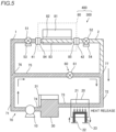
- the evaporator 80 is connected to the inlet connection 41 and the outlet connection 42.
- the inlet side shut-off valve 51 is in a closed state, and the outlet side shut-off valve 52 is in an open state.
- a heat source 81 is not generating heat.
- a liquid refrigerant 1 is pumped from a pump 10.
- the liquid refrigerant 1 flows through a first refrigerant flow path 71.
- the inlet side shut-off valve 51 is in a fully closed state, and thus the liquid refrigerant 1 flows into a bypass line 75 at a bifurcation 76 of the first refrigerant flow path 71, except for the refrigerant that flows between the bifurcation 76 and the inlet side shut-off valve 51.
- the liquid refrigerant 1 that has flowed into the bypass line 75 flows into a junction 77 of a second refrigerant flow path 72.
- the liquid refrigerant 1 that has flowed into the junction 77 flows through the second refrigerant flow path 72 into a condenser 20.
- the refrigerant that has flowed into the condenser 20 flows through a third refrigerant flow path 73 into the reservoir 30.
- the refrigerant that has flowed into the reservoir 30 flows through a fourth refrigerant flow path 74 into the pump 10.
- the liquid refrigerant 1 is not pumped from the pump 10 to the evaporator 80. Therefore, the liquid refrigerant 1 circulating through the circulation device 300 for a two-phase cooling system does not flow into the evaporator 80 in the refrigerant recovery state. Then, immediately after the inlet side shut-off valve 51 is fully closed, the liquid refrigerant 1 remains in a refrigerant flow path 83 inside the evaporator 80. Although the heat source 81 has stopped generating heat, the temperature inside the evaporator 80 rises due to heat from the outside air.
- the gas-phase refrigerant of the gas-liquid mixed refrigerant 2 in the evaporator 80 flows out of the evaporator 80 toward the junction 77 of the second refrigerant flow path 72, and flows out so as to push the liquid refrigerant of the gas-liquid mixed refrigerant 2 in the evaporator 80 out of the evaporator 80. Then, at the junction 77, the gas-liquid mixed refrigerant 2 that has flowed out of the evaporator 80 merges with the liquid refrigerant 1 that has flowed in from the bypass line 75, and the gas-phase refrigerant contained in the merged gas-liquid mixed refrigerant 2 is condensed.
- the refrigerant remaining in the refrigerant flow path inside the evaporator 80 is recovered into the reservoir 30.
- the flow path 83 inside the evaporator 80 cannot be evacuated, and thus all of the refrigerant inside the evaporator 80 cannot be recovered.
- the set liquid level 5 is set based on the liquid level 4 of the liquid refrigerant 1 stored in the reservoir 30 in a state in which the evaporator 80 is not connected.
- the set liquid level 5 refers to the liquid level of the liquid refrigerant 1 stored in the reservoir 30 in the refrigerant recovery state, which is set by subtracting a margin such as the amount of refrigerant in the evaporator 80 that cannot be recovered described above from the liquid level 4 of the liquid refrigerant 1 stored in the reservoir 30 in a state in which the evaporator 80 is not connected. Therefore, when the liquid level of the liquid refrigerant stored in the reservoir 30 in the refrigerant recovery state becomes equal to or greater than the set liquid level 5, it can be considered that the refrigerant remaining in the evaporator 80 has been recovered into reservoir 30.
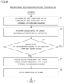
- step S3 when the acquired liquid level 3 of the liquid refrigerant 1 is equal to or greater than the set liquid level 5 (Yes in step S3), the process advances to step S4, and when the acquired liquid level 3 is less than the set liquid level 5 (No in step S3), the process advances to step S2.
- step S4 the controller 91 closes the outlet side shut-off valve 52 using the outlet side shut-off valve opening-closing mechanism 54. After that, the process advances to step S5.
- step S5 the controller 91 stops the operation of the pump 10. After that, the refrigerant recovery process is terminated.
- the circulation device 300 for a two-phase cooling system further includes the inlet side shut-off valve 51 between the bifurcation 76 at which the bypass line 75 branches on the downstream side of the pump 10, and the inlet connection 41 to open and close the refrigerant flow path, and when the refrigerant is recovered from the evaporator 80, the refrigerant is circulated through the bypass line 75 without passing through the evaporator 80, and the refrigerant in the evaporator 80 is led to the condenser 20, in the refrigerant recovery state in which the evaporator 80 is connected to the inlet connection 41 and the outlet connection 42 and the inlet side shut-off valve 51 is closed.
- the inlet side shut-off valve 51 is closed such that the circulating liquid refrigerant 1 does not flow into the evaporator 80 and heat is input to the evaporator 80 from the outside air, and thus the temperature inside the evaporator 80 rises. Therefore, the temperature and pressure of the liquid refrigerant 1 remaining in the evaporator 80 rise, and a portion of the liquid refrigerant 1 in the evaporator 80 is evaporated and changes into the gas-liquid mixed refrigerant 2.
- a pressure difference is generated between the pressure of the gas-phase refrigerant contained in the gas-liquid mixed refrigerant 2 in the evaporator 80 and the pressure of the liquid refrigerant 1 circulating in the path from the junction 77 of the second refrigerant flow path 72 through the condenser 20, the reservoir 30, the pump 10, and the bypass line 75, and thus the gas-liquid mixed refrigerant 2 in the evaporator 80 can be caused to flow out of the evaporator 80 toward the junction 77 of the second refrigerant flow path 72.
- the liquid refrigerant 1 in the evaporator 80 can be changed into the gas-liquid mixed refrigerant 2 due to the rise in the temperature inside the evaporator 80, and thus there is no need to provide additional equipment such as a heater to change the refrigerant into the gas-liquid mixed refrigerant 2. For these reasons, an increase in the number of components and the complexity of the structure can be reduced or prevented, and the refrigerant remaining in the refrigerant flow path 83 inside the evaporator 80 can be easily recovered.
- the circulation device 300 for a two-phase cooling system further includes the detector 31 to detect the amount of recovered refrigerant, and the controller 91 configured or programmed to stop the operation of the pump 10 to terminate the refrigerant recovery process based on the detection result of the detector 31. Accordingly, the refrigerant recovery process can be terminated based on the detection result of the detector 31 that detects the amount of recovered refrigerant. Therefore, the refrigerant recovery process can be reliably performed based on the detection result of the detector 31 that detects the amount of recovered refrigerant.
- the circulation device 300 for a two-phase cooling system further includes the reservoir 30 downstream of the condenser 20 and upstream of the pump 10, and the detector 31 is operable to detect the amount of refrigerant stored in the reservoir 30 as the amount of recovered refrigerant. Accordingly, based on the detection result of the amount of refrigerant stored in the reservoir 30 as the amount of recovered refrigerant, the operation of the pump 10 can be stopped to terminate the refrigerant recovery process. Therefore, the detection result of the amount of recovered refrigerant can be acquired by the simple configuration of the detector 31, and thus the complexity of the structure of the circulation device 300 for a two-phase cooling system can be reduced or prevented.
- the controller 91 is configured or programmed to, in the refrigerant recovery state, perform a control to stop the operation of the pump 10 to terminate the refrigerant recovery process when the amount of stored refrigerant detected by the detector 31 while the refrigerant is circulating through the bypass line 75 without passing through the evaporator 80 becomes equal to or greater than the set storage amount, which is set in advance. Accordingly, based on the set storage amount, it is possible to more easily detect whether the refrigerant remaining in the evaporator 80 has been recovered into the reservoir 30. Therefore, based on the set storage amount, the refrigerant recovery process can be more easily and reliably performed.
- the circulation device 300 for a two-phase cooling system further includes the outlet side shut-off valve 52 between the outlet connection 42 and the connection portion to which the bypass line 75 is connected on the downstream side of the outlet connection 42 to open and close the refrigerant flow path, and the controller 91 is configured or programmed to, based on the detection result of the detector 31, perform a control to close the outlet side shut-off valve 52 to prevent the refrigerant from flowing out from the outlet side shut-off valve 52 toward the outlet connection 42.
- the refrigerant circulation method includes circulating the refrigerant not through the evaporator 80 but through the bypass line 75 and leading the refrigerant in the evaporator 80 to the condenser 20, in the refrigerant recovery state in which the evaporator 80 is connected to the inlet connection 41 and the outlet connection 42 and the inlet side shut-off valve 51 between the bifurcation 76 at which the bypass line 75 branches and the inlet connection 41 is closed, when the refrigerant is recovered from the evaporator 80, and stopping the refrigerant circulation to terminate the refrigerant recovery process based on the detection result of the amount of recovered refrigerant.
- the inlet side shut-off valve 51 is closed such that the circulating liquid refrigerant 1 does not flow into the evaporator 80 and heat is input to the evaporator 80 from the outside air, and thus the temperature inside the evaporator 80 rises. Therefore, the temperature and pressure of the liquid refrigerant 1 remaining in the evaporator 80 rise, and a portion of the liquid refrigerant 1 is evaporated and changes into the gas-liquid mixed refrigerant 2.
- a pressure difference is generated between the pressure of the gas-phase refrigerant contained in the gas-liquid mixed refrigerant 2 in the evaporator 80 and the pressure of the liquid refrigerant 1 circulating in the path from the junction 77 of the second refrigerant flow path 72 through the condenser 20, the reservoir 30, the pump 10, and the bypass line 75, and thus the gas-liquid mixed refrigerant 2 in the evaporator 80 can be caused to flow out of the evaporator 80 toward the junction 77 of the second refrigerant flow path 72.
- the liquid refrigerant 1 in the evaporator 80 can be changed into the gas-liquid mixed refrigerant 2 due to the rise in the temperature inside the evaporator 80, and thus there is no need to provide additional equipment such as a heater to change the refrigerant into the gas-liquid mixed refrigerant 2. For these reasons, an increase in the number of components and the complexity of the structure can be reduced or prevented, and the refrigerant remaining in the refrigerant flow path 83 inside the evaporator 80 can be easily recovered.
- the present invention is not limited to this.
- the flow regulator 60 may not be provided in the bypass line 75.
- the distributions of the flow rate of the refrigerant flowing into the evaporator 80 and the flow rate of the refrigerant flowing into the bypass line 75 in a state in which the evaporator 80 is connected can be adjusted by the pipe diameter and/or flow path length of the bypass line 75, for example.
- the present invention is not limited to this.
- the flow rate of the refrigerant flowing into the evaporator 80 may be equal to the flow rate of the refrigerant flowing into the bypass line 75, or the flow rate of the refrigerant flowing into the evaporator 80 may be less than the flow rate of the refrigerant flowing into the bypass line 75.
- the flow regulator 60 may include a flow rate adjustment valve 62.
- the flow rate adjustment valve 62 is not particularly limited as long as the same is a known valve such as a needle valve that can be shut off and adjust the flow rate.
- the opening degree adjustment of the flow rate adjustment valve 62 may be performed manually or by computer control.
- the opening degree of the flow rate adjustment valve 62 may be adjusted according to the cooling level of the target to be cooled, which is the heat source 81.
- the opening degree of the flow rate adjustment valve 62 in a state in which the need for cooling the target to be cooled is lower than in the normal operating state can be larger than the opening degree of the flow rate adjustment valve 62 in the normal operating state.
- the flow rate of the refrigerant flowing into the evaporator 80 can be less than the flow rate of the refrigerant flowing into the bypass line 75, for example.
- the present invention is not limited to this.
- both the inlet side shut-off valve 51 and the outlet side shut-off valve 52 may not be provided, or either the inlet side shut-off valve 51 or the outlet side shut-off valve 52 may not be provided.
- bypass line 75 is connected to the portion downstream of the outlet connection 42 and upstream of the condenser 20 in the aforementioned first embodiment, the present invention is not limited to this.
- the bypass line 75 may be directly connected to the condenser 20 and may not be connected to the flow path between the outlet connection 42 and the condenser 20.
- the present invention is not limited to this.
- the reservoir 30 may not be provided.
- the circulation device 100 for a two-phase cooling system is portable has been shown in the first embodiment, the present invention is not limited to this.
- the circulation device 100 for a two-phase cooling system may be fixed in position.
- the detector 31 is a liquid level sensor, and detects the amount of refrigerant stored in the reservoir 30 as the amount of recovered refrigerant by measuring the liquid level 3 of the liquid refrigerant 1 stored in the reservoir 30
- the present invention is not limited to this.
- the detector may be a differential pressure level sensor, and may detect the amount of refrigerant stored in the reservoir as the amount of recovered refrigerant by measuring the height of the liquid level based on a difference between a pressure at the bottom of the reservoir and a pressure at the liquid level.
- the detector may be another known sensor.
- the set liquid level 5 is set by the controller 91
- the present invention is not limited to this.
- the set liquid level 5 may be set by a user.
- the amount of change 6 per unit time of the liquid level of the liquid refrigerant 1 stored in the reservoir 30 is the largest, and as time t passes, the amount of change 6 per unit time of the liquid level of the liquid refrigerant 1 becomes smaller. Therefore, the amount of change per unit time in the liquid level of the liquid refrigerant 1 is set in advance as a set change amount 7.
- the set change amount 7 is a reference value at which it can be considered that the refrigerant remaining in the evaporator 80 has been recovered into the reservoir 30.
- the set change amount 7 is set in advance by the user and is stored in the storage 92.
- the controller 91 performs a control to close the inlet side shut-off valve 51 using the inlet side shut-off valve opening-closing mechanism 53, a control to close the outlet side shut-off valve 52 using the outlet side shut-off valve opening-closing mechanism 54 based on the set storage amount, and a control to stop the operation of the pump 10 based on the set storage amount
- the present invention is not limited to this.
- the user may perform any or all of an operation to close the inlet side shut-off valve 51, an operation to close the outlet side shut-off valve 52 based on the set storage amount, and an operation to stop the operation of the pump 10 based on the set storage amount.
- the controller may not be provided.
- the circulation device 300 for a two-phase cooling system may further include a notifier 93, and the controller 91 may notify the user using the notifier 93 that the amount of stored refrigerant detected by the detector 31 has become equal to or greater than the set storage amount, or that the amount of change in the amount of stored refrigerant detected by the detector 31 has become equal to or less than the set change amount.
- the user can recognize that the amount of stored refrigerant detected by the detector 31 has become equal to or greater than the set storage amount, or that the amount of change in the amount of stored refrigerant detected by the detector 31 has become equal to or less than the set change amount, and thus the user can be promptly caused to execute an operation to close the outlet side shut-off valve 52 and an operation to stop the operation of the pump 10.
- the user When the user is notified of the above by the notifier 93, the user performs an operation to close the outlet side shut-off valve 52 and an operation to stop the operation of the pump 10.
- the notifier 93 may include an audio output 95 instead of or in addition to the display 94, and the controller 91 may control the audio output 95 to announce that "the refrigerant has been recovered" when the amount of stored refrigerant detected by the detector 31 becomes equal to or greater than the set storage amount, which is set in advance, or when the amount of change in the amount of stored refrigerant detected by the detector 31 becomes equal to or less than the set change amount.
- the circulation device for a two-phase cooling system according to item 1 or 2, further comprising: a flow regulator in the bypass line.
- the circulation device for a two-phase cooling system according to any one of items 1 to 8, further comprising: a reservoir downstream of the condenser and upstream of the pump.
Landscapes
- Engineering & Computer Science (AREA)
- Physics & Mathematics (AREA)
- Thermal Sciences (AREA)
- Mechanical Engineering (AREA)
- General Engineering & Computer Science (AREA)
- Life Sciences & Earth Sciences (AREA)
- Sustainable Development (AREA)
- Microelectronics & Electronic Packaging (AREA)
- Air-Conditioning For Vehicles (AREA)
Applications Claiming Priority (2)
| Application Number | Priority Date | Filing Date | Title |
|---|---|---|---|
| JP2022086867 | 2022-05-27 | ||
| PCT/JP2023/017737 WO2023228765A1 (ja) | 2022-05-27 | 2023-05-11 | 二相冷却システム用循環装置および二相冷却システム用循環装置における冷媒循環方法 |
Publications (1)
| Publication Number | Publication Date |
|---|---|
| EP4534941A1 true EP4534941A1 (en) | 2025-04-09 |
Family
ID=88919066
Family Applications (1)
| Application Number | Title | Priority Date | Filing Date |
|---|---|---|---|
| EP23811640.4A Pending EP4534941A1 (en) | 2022-05-27 | 2023-05-11 | Circulation device for two-phase cooling system and refrigerant circulation method in circulation device for two-phase cooling system |
Country Status (7)
| Country | Link |
|---|---|
| US (1) | US20250093079A1 (https=) |
| EP (1) | EP4534941A1 (https=) |
| JP (1) | JP7831594B2 (https=) |
| KR (1) | KR20250004027A (https=) |
| CN (1) | CN119278349A (https=) |
| TW (1) | TWI886486B (https=) |
| WO (1) | WO2023228765A1 (https=) |
Families Citing this family (1)
| Publication number | Priority date | Publication date | Assignee | Title |
|---|---|---|---|---|
| WO2026053407A1 (ja) * | 2024-09-09 | 2026-03-12 | 株式会社島津製作所 | 二相冷却システム用循環装置および二相冷却システム |
Family Cites Families (10)
| Publication number | Priority date | Publication date | Assignee | Title |
|---|---|---|---|---|
| JPS62119620A (ja) * | 1985-11-20 | 1987-05-30 | Fujitsu Ltd | 冷却水供給装置 |
| US6828675B2 (en) | 2001-09-26 | 2004-12-07 | Modine Manufacturing Company | Modular cooling system and thermal bus for high power electronics cabinets |
| JP4258363B2 (ja) * | 2003-02-20 | 2009-04-30 | 三菱電機株式会社 | 冷凍空調装置、冷凍空調装置の運転方法 |
| JP4063229B2 (ja) * | 2004-02-19 | 2008-03-19 | 三菱電機株式会社 | 配管洗浄方法および配管洗浄装置 |
| CN101382362A (zh) * | 2007-09-04 | 2009-03-11 | 乐金电子(天津)电器有限公司 | 窗式空调器卸荷阀管路结构 |
| IT1400806B1 (it) * | 2010-07-05 | 2013-07-02 | Emerson Network Power Srl | Dispositivo economizzatore di consumi per macchine refrigeratrici di tipo chiller |
| JP6998780B2 (ja) * | 2018-02-02 | 2022-01-18 | 株式会社デンソー | 冷凍サイクル装置 |
| KR102518852B1 (ko) * | 2018-11-07 | 2023-04-10 | 신와 콘트롤즈 가부시키가이샤 | 유체 온조 시스템 및 냉동 장치 |
| JP2022068386A (ja) * | 2019-03-14 | 2022-05-10 | 株式会社光商事 | 調圧・バイパス制御ユニット |
| CN112413941B (zh) * | 2020-11-24 | 2024-07-09 | 珠海格力电器股份有限公司 | 液泵系统、空调系统及液泵系统的控制方法 |
-
2023
- 2023-05-11 JP JP2024523033A patent/JP7831594B2/ja active Active
- 2023-05-11 KR KR1020247039756A patent/KR20250004027A/ko active Pending
- 2023-05-11 CN CN202380042883.XA patent/CN119278349A/zh active Pending
- 2023-05-11 WO PCT/JP2023/017737 patent/WO2023228765A1/ja not_active Ceased
- 2023-05-11 EP EP23811640.4A patent/EP4534941A1/en active Pending
- 2023-05-15 TW TW112117867A patent/TWI886486B/zh active
-
2024
- 2024-11-26 US US18/961,310 patent/US20250093079A1/en active Pending
Also Published As
| Publication number | Publication date |
|---|---|
| US20250093079A1 (en) | 2025-03-20 |
| WO2023228765A1 (ja) | 2023-11-30 |
| JP7831594B2 (ja) | 2026-03-17 |
| CN119278349A (zh) | 2025-01-07 |
| JPWO2023228765A1 (https=) | 2023-11-30 |
| TW202403250A (zh) | 2024-01-16 |
| KR20250004027A (ko) | 2025-01-07 |
| TWI886486B (zh) | 2025-06-11 |
Similar Documents
| Publication | Publication Date | Title |
|---|---|---|
| DK2718642T3 (en) | Multi-evaporator cooling circuits | |
| US20250093079A1 (en) | Circulation device for two-phase cooling system and refrigerant circulation method in circulation device for two-phase cooling system | |
| US10352592B2 (en) | Ejector system and methods of operation | |
| JP2012243035A (ja) | 電子機器の冷却システム | |
| US10794160B2 (en) | Geothermal heat recovery device and geothermal heat recovery device operating method | |
| CN106574812A (zh) | 室外机以及制冷循环装置 | |
| CN115956316A (zh) | 电池调温系统 | |
| US20220238896A1 (en) | Cooling system for two-phase refrigerant | |
| EP3163219A1 (en) | Chiller system | |
| US20250321030A1 (en) | Variable-frequency drive cooling device, cooling method and air conditioning apparatus | |
| US11994325B2 (en) | Control device, refrigerator, control method, and abnormality detection method | |
| US12359878B2 (en) | Dryout detection for cooling device | |
| Xia et al. | A review on the operational instability of vapor compression system | |
| JPWO2023228765A5 (https=) | ||
| JP2007127334A (ja) | 熱媒加熱冷却装置 | |
| CN101688710B (zh) | 用于在吸收式冷却器中进行排热的方法和系统 | |
| JP6987988B2 (ja) | 冷却装置、冷却装置を備えた露光装置、冷却装置を備えた産業用機器 | |
| US12589631B2 (en) | Method for controlling a refrigeration system of a vehicle | |
| CN106996663A (zh) | 用于板式蒸发器的气液分离器与板式蒸发器 | |
| EP4403848A1 (en) | Air conditioner | |
| KR20240051749A (ko) | 오일회수시스템, 이를 포함하는 냉동시스템 및 냉동시스템의 제어방법 | |
| JP7265963B2 (ja) | ターボ冷凍機 | |
| TW201437581A (zh) | 用於冷凍劑系統之壓力控制技術 | |
| KR102869909B1 (ko) | 오일회수시스템, 이를 포함하는 냉동시스템 및 냉동시스템의 제어방법 | |
| CN121499129A (zh) | 一种基于传感器载气降膜式换热器测试控制方法及系统 |
Legal Events
| Date | Code | Title | Description |
|---|---|---|---|
| STAA | Information on the status of an ep patent application or granted ep patent |
Free format text: STATUS: THE INTERNATIONAL PUBLICATION HAS BEEN MADE |
|
| PUAI | Public reference made under article 153(3) epc to a published international application that has entered the european phase |
Free format text: ORIGINAL CODE: 0009012 |
|
| STAA | Information on the status of an ep patent application or granted ep patent |
Free format text: STATUS: REQUEST FOR EXAMINATION WAS MADE |
|
| 17P | Request for examination filed |
Effective date: 20241219 |
|
| AK | Designated contracting states |
Kind code of ref document: A1 Designated state(s): AL AT BE BG CH CY CZ DE DK EE ES FI FR GB GR HR HU IE IS IT LI LT LU LV MC ME MK MT NL NO PL PT RO RS SE SI SK SM TR |
|
| DAV | Request for validation of the european patent (deleted) | ||
| DAX | Request for extension of the european patent (deleted) |