EP4534893A1 - Lampeneinheit und verfahren zur belüftung des körpergehäuses der lampe - Google Patents
Lampeneinheit und verfahren zur belüftung des körpergehäuses der lampe Download PDFInfo
- Publication number
- EP4534893A1 EP4534893A1 EP23816132.7A EP23816132A EP4534893A1 EP 4534893 A1 EP4534893 A1 EP 4534893A1 EP 23816132 A EP23816132 A EP 23816132A EP 4534893 A1 EP4534893 A1 EP 4534893A1
- Authority
- EP
- European Patent Office
- Prior art keywords
- lamp unit
- pump
- ventilation
- opening portion
- body housing
- Prior art date
- Legal status (The legal status is an assumption and is not a legal conclusion. Google has not performed a legal analysis and makes no representation as to the accuracy of the status listed.)
- Withdrawn
Links
Images


Classifications
-
- F—MECHANICAL ENGINEERING; LIGHTING; HEATING; WEAPONS; BLASTING
- F21—LIGHTING
- F21S—NON-PORTABLE LIGHTING DEVICES; SYSTEMS THEREOF; VEHICLE LIGHTING DEVICES SPECIALLY ADAPTED FOR VEHICLE EXTERIORS
- F21S45/00—Arrangements within vehicle lighting devices specially adapted for vehicle exteriors, for purposes other than emission or distribution of light
- F21S45/30—Ventilation or drainage of lighting devices
- F21S45/33—Ventilation or drainage of lighting devices specially adapted for headlamps
-
- F—MECHANICAL ENGINEERING; LIGHTING; HEATING; WEAPONS; BLASTING
- F21—LIGHTING
- F21S—NON-PORTABLE LIGHTING DEVICES; SYSTEMS THEREOF; VEHICLE LIGHTING DEVICES SPECIALLY ADAPTED FOR VEHICLE EXTERIORS
- F21S45/00—Arrangements within vehicle lighting devices specially adapted for vehicle exteriors, for purposes other than emission or distribution of light
- F21S45/20—Promoting gas flow in lighting devices, e.g. directing flow toward the cover glass for demisting
-
- F—MECHANICAL ENGINEERING; LIGHTING; HEATING; WEAPONS; BLASTING
- F21—LIGHTING
- F21V—FUNCTIONAL FEATURES OR DETAILS OF LIGHTING DEVICES OR SYSTEMS THEREOF; STRUCTURAL COMBINATIONS OF LIGHTING DEVICES WITH OTHER ARTICLES, NOT OTHERWISE PROVIDED FOR
- F21V15/00—Protecting lighting devices from damage
- F21V15/01—Housings, e.g. material or assembling of housing parts
-
- F—MECHANICAL ENGINEERING; LIGHTING; HEATING; WEAPONS; BLASTING
- F21—LIGHTING
- F21V—FUNCTIONAL FEATURES OR DETAILS OF LIGHTING DEVICES OR SYSTEMS THEREOF; STRUCTURAL COMBINATIONS OF LIGHTING DEVICES WITH OTHER ARTICLES, NOT OTHERWISE PROVIDED FOR
- F21V31/00—Gas-tight or water-tight arrangements
- F21V31/03—Gas-tight or water-tight arrangements with provision for venting
-
- F—MECHANICAL ENGINEERING; LIGHTING; HEATING; WEAPONS; BLASTING
- F21—LIGHTING
- F21W—INDEXING SCHEME ASSOCIATED WITH SUBCLASSES F21K, F21L, F21S and F21V, RELATING TO USES OR APPLICATIONS OF LIGHTING DEVICES OR SYSTEMS
- F21W2102/00—Exterior vehicle lighting devices for illuminating purposes
-
- F—MECHANICAL ENGINEERING; LIGHTING; HEATING; WEAPONS; BLASTING
- F21—LIGHTING
- F21Y—INDEXING SCHEME ASSOCIATED WITH SUBCLASSES F21K, F21L, F21S and F21V, RELATING TO THE FORM OR THE KIND OF THE LIGHT SOURCES OR OF THE COLOUR OF THE LIGHT EMITTED
- F21Y2101/00—Point-like light sources
-
- F—MECHANICAL ENGINEERING; LIGHTING; HEATING; WEAPONS; BLASTING
- F21—LIGHTING
- F21Y—INDEXING SCHEME ASSOCIATED WITH SUBCLASSES F21K, F21L, F21S and F21V, RELATING TO THE FORM OR THE KIND OF THE LIGHT SOURCES OR OF THE COLOUR OF THE LIGHT EMITTED
- F21Y2115/00—Light-generating elements of semiconductor light sources
- F21Y2115/10—Light-emitting diodes [LED]
Definitions
- the present invention relates to a lamp unit and a ventilation method for a body housing of a lamp.
- Patent Literature 1 describes a vehicle lamp including a lamp chamber composed of a lamp body and a light-transmitting cover.
- a ventilation hole is formed in at least one portion of the light-transmitting cover to allow communication between the inside space and external space of the lamp chamber.
- a filter with waterproof and moisture-diffusing properties is attached to cover the ventilation hole.
- Patent Literature 1 JP 2018-45879 A
- Patent Literature 1 leaves room for reexamination from the viewpoint of preventing fogging inside a lamp or effectively removing fogging that has occurred inside a lamp.
- the present invention provides a lamp unit that is advantageous for preventing fogging inside a lamp or effectively removing fogging that has occurred inside a lamp.
- the present invention provides a lamp unit including:
- the present invention also provides a ventilation method for a body housing of a lamp
- the above lamp unit is advantageous for preventing fogging inside a lamp or effectively removing fogging that has occurred inside a lamp.
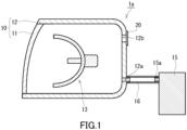
- a lamp unit 1a includes a body housing 10, a light source 13, and a pump 15.
- the body housing 10 includes a light-transmitting member 11, a body wall 12, a first opening portion 12a, and a second opening portion 12b.
- the body wall 12 is joined to the light-transmitting member 11 to form a housing.
- the first opening portion 12a and the second opening portion 12b are positioned in the body wall 12 and each form an opening communicating with the external space of the housing.
- the light source 13 is disposed inside the body housing 10.
- the pump 15 has a gas discharge port 15a, and the gas discharge port 15a is connected to the first opening portion 12a.
- the gas discharge port 15a is connected to the first opening portion 12a, for example, via a flow path member, such as a tube.
- the gas discharge port 15a may be directly connected to the first opening portion 12a.
- the lamp unit 1a for example, operation of the pump 15 sends air from the external space into the inside of the housing of the lamp unit 1a through the first opening portion 12a.
- moisture present inside the housing of the lamp unit 1a is directed to the outside of the housing through the second opening portion 12b. Therefore, in the lamp unit 1a, fogging is less likely to occur on the inner surface of the light-transmitting member 11. Even if fogging occurs on the inner surface of the light-transmitting member 11, the fogging is likely to be effectively removed.
- the light-transmitting member 11 is disposed, for example, in front of the light source 13 in the traveling direction of light generated from the light source 13. In the lamp unit 1a, the light-transmitting member 11 transmits light generated from the light source 13.
- the body wall 12 is disposed, for example, to cover the rear and lateral sides of the light source 13 with respect to the traveling direction of light generated from the light source 13.
- the body wall 12 is joined to the light-transmitting member 11 in a state where the body wall 12 is in contact with the periphery of the light-transmitting member 11.
- the manner of joining the body wall 12 and the light-transmitting member 11 to each other is not limited to a particular manner.
- the body wall 12 and the light-transmitting member 11 are joined to each other, for example, by snap-fitting or screwing.
- the body wall 12 is composed of, for example, a non-light-transmitting member.
- the light source 13 is not limited to a particular light source.
- the light source 13 may be a halogen lamp, an HID lamp, or an LED lamp.
- the lamp unit 1a includes, for example, a ventilation member 20.
- the ventilation member 20 is a member for ventilation between the body housing 10 and the external space of the body housing 10.
- the ventilation member 20 is provided at the second opening portion 12b.
- the ventilation member 20 is, for example, attached to a portion of the body wall 12 that abuts the second opening portion 12b such that the ventilation member 20 covers the second opening portion 12b in a ventilatable manner.
- the ventilation member 20 is not limited to a particular member as long as the ventilation member 20 allows ventilation between the body housing 10 and the external space of the body housing 10.
- the ventilation member 20 is, for example, a gas-permeable member that prevents the entry of foreign substances such as water and dust.
- the ventilation member 20 may include a known gas-permeable membrane, or may include a porous body, such as a woven fabric, a nonwoven fabric, or foam, a mesh, or a net.
- the gas-permeable membrane may be subjected to a liquid-repellent treatment as necessary.
- the liquid-repellent treatment is performed, for example, by forming, on the gas-permeable membrane, a liquid-repellent coating film containing a fluorine surface modifier having a perfluoroalkyl group.
- the formation of the liquid-repellent coating film is not limited to a particular method, and is performed, for example, by coating a porous resin membrane with a solution or dispersion of a fluorine surface modifier having a perfluoroalkyl group by a method such as air spray coating, electrostatic spray coating, dip coating, spin coating, roll coating, curtain flow coating, or impregnation.
- electrodeposition coating or plasma polymerization may be employed to form the liquid-repellent coating film.
- the pump 15 is not limited to a particular pump as long as the pump 15 has the gas discharge port 15a.
- the pump 15 has a maximum discharge pressure P dis_max of, for example, 0.5 to 20 kPa. In this case, in the lamp unit 1a, fogging is less likely to occur on the inner surface of the light-transmitting member 11. Even if fogging occurs, the fogging is likely to be effectively removed without breakage of the body housing 10 or the ventilation member 20.
- the maximum discharge pressure P dis_max is desirably 10 kPa or less, more desirably 5 kPa or less, and even more desirably 4 kPa or less.
- the arrangement of the first opening portion 12a and the second opening portion 12b in the body wall 12 is not limited to a particular arrangement.
- the first opening portion 12a and the second opening portion 12b are arranged, for example, at opposite end portions in a specific direction.
- the first opening portion 12a and the second opening portion 12b, in the respective portions of the outer surface of the body wall 12, are arranged at a pair of corners in a diagonal relationship.
- the body wall 12 may have a plurality of the first opening portions 12a.
- the lamp unit 1a may include a plurality of the pumps 15, with the gas discharge ports 15a of the plurality of pumps 15 connected to separate first opening portions 12a.
- the gas discharge port 15a of a single pump 15 may be connected to the plurality of first opening portions 12a.
- the body wall 12 may have a plurality of the second opening portions 12b. As shown in FIG. 2B , the body wall 12 may have two second opening portions 12b, for example. In plan view of the portion of the outer surface of the body wall 12 that forms the rear of the lamp unit 1a, the first opening portion 12a and each of the plurality of second opening portions 12b are arranged, for example, at opposite end portions in different specific directions.
- the two second opening portions 12b, in the respective portions of the outer surface of the body wall 12, are arranged, for example, at a pair of corners adjacent to each other. For example, as shown in FIG.
- one of the plurality of second opening portions 12b is arranged away from a straight line L that intersects both the first opening portion 12a and another second opening portion 12b. At least one of the first opening portion 12a and the plurality of second opening portions 12b may be positioned in the side portion of the body wall 12.
- the body wall 12 may have an opening portion communicating with the external space of the body housing 10, in addition to the first opening portion 12a and the second opening portion 12b.
- the body wall 12 has three opening portions or less.
- the shape of the first opening portion 12a and the second opening portion 12b are not limited to particular shapes.
- the end portion of the opening portion that abuts the external space of the body housing 10 may be positioned flush with the periphery of the opening portion, or may be positioned at the tip of a portion protruding from the periphery of the opening portion.
- the ventilation member 20 may be a patch-type ventilation member, a snap-fit type ventilation member, a cap-type ventilation member, or any other type of ventilation member.
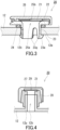
- FIG. 3 shows an example of the ventilation member 20, where the ventilation member 20 is a snap-fit type ventilation member.
- the ventilation member 20 includes a gas-permeable membrane 21, a supporting portion 22, and a protruding portion 23.
- the supporting portion 22 is an annular and plate-shaped portion in which a through hole forming a portion of a ventilation path 25a is formed at the center, and the gas-permeable membrane 21 is fixed to the supporting portion 22 to cover the through hole.
- the protruding portion 23 is a tubular portion protruding from the supporting portion 22 at the center of the supporting portion 22.
- the protruding portion 23 includes a plurality of leg portions 23g arranged away from each other around the axis of the protruding portion 23.
- each of the plurality of leg portions 23g has a protrusion 23a protruding outward in a direction perpendicular to the axis of the supporting portion 22.
- the protrusion 23a faces an inner surface 12m of the body wall 12.
- the ventilation member 20 is configured such that the protrusion 23a allows the ventilation member 20 to snap-fit onto the body wall 12.
- the ventilation member 20 further includes a sealing member 24, for example.
- the sealing member 24 is disposed around the protruding portion 23 at a corner formed by the outer surface of the protruding portion 23 and the supporting portion 22.
- the sealing member 24 is an annular member and is disposed in contact with the supporting portion 22 and the outer surface of the body wall 12. This seals the ventilation path 25a against the space outside the body wall 12 between the supporting portion 22 and the outer surface of the body wall 12.
- FIG. 4 shows an example of the ventilation member 20, where the ventilation member 20 is a cap-type ventilation member.
- the cap-type ventilation member 20 includes, for example, the gas-permeable membrane 21, a cap 27, and an inner member 28.
- the ventilation member 20 is attached to the body wall 12 with the inner surface of the inner member 28 in contact with the outer surface of a protruding portion 12p. Consequently, an airtight state is maintained between the inner surface of the inner member 28 and the outer surface of the protruding portion 12p.
- the protruding portion 12p is a tubular portion protruding outward in the body wall 12, inside which the second opening portion 12b is formed.
- the inner member 28 is a tubular member.
- the combination of the body housing 10, the pump 15, and the ventilation member 20 is not limited to a particular combination.
- the body housing 10, the pump 15, and the ventilation member 20 form a combination satisfying the requirements represented by the following expressions (Ia) and (Ib).
- fogging is less likely to occur on the inner surface of the light-transmitting member 11. Even if fogging occurs, the fogging is likely to be more effectively removed.
- p is the pressure [kPa] inside the body housing 10 during operation of the pump 15
- t is the discharge time [s] of the pump 15
- P is the air permeability coefficient [cm 3 /(Pa•s•cm 2 )] of the ventilation member 20
- A is the permeable area [cm 2 ] of the ventilation member 20
- V is the spatial volume [cm 3 ] inside the lamp unit 1a.
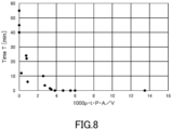
- the pressure p is a gauge pressure. 1000 p ⁇ t ⁇ P ⁇ A / V ⁇ 3.0 0 ⁇ t ⁇ 300
- the combination of the body housing 10, the pump 15, and the ventilation member 20 may satisfy the requirement 1000p•t•P•A/V ⁇ 4, 1000p•t•P•A/V ⁇ 5, or 1000p•t•P•A/V ⁇ 10.
- the combination of the body housing 10, the pump 15, and the ventilation member 20 satisfies the requirement 1000p•t•P•A/V ⁇ 20, for example.
- the pressure p inside the body housing 10 can be regulated, for example, by a valve disposed between the gas discharge port 15a and the first opening portion 12a.
- the function may be used to regulate the pressure p.
- the time t is desirably 240 seconds or less, and more desirably 180 seconds. Owing to the satisfaction of the requirement (Ia), fogging is less likely to occur on the inner surface of the light-transmitting member 11, even with a discharge time t of the pump 15 being as short as described above. Even if fogging occurs, the fogging is likely to be effectively removed.
- the time t may be 10 seconds or more.
- the permeability coefficient P is not limited to a particular value.
- the permeability coefficient P is, for example, adjusted such that the requirement in (Ia) is satisfied.
- the permeability coefficient P is, for example, 0.00008 to 0.80293 [cm 3 /(Pa•s•cm 2 )]. In this case, the requirement (Ia) is likely to be satisfied and fogging is less likely to occur on the inner surface of the light-transmitting member 11. Even if fogging occurs, the fogging is likely to be more effectively removed.
- the permeability coefficient P is desirably 0.00008 to 0.8 [cm 3 /(Pa•s•cm 2 )], more desirably 0.0008 to 0.16 [cm 3 /(Pa•s•cm 2 )], and even more desirably 0.004 to 0.03 [cm 3 /(Pa•s•cm 2 )].
- the permeable area A of the ventilation member 20 is the area of the air-permeable portion of the ventilation member 20.
- the effective area of the air-permeable portion of the gas-permeable membrane corresponds to the permeable area A.
- the ventilation member 20 for example, in the case where the periphery of the gas-permeable membrane is fixed to a given supporting member and the inner side of the periphery of the gas-permeable membrane abuts the ventilation path, the area of the portion of the gas-permeable membrane that abuts the ventilation path on the inner side of the periphery of the gas-permeable membrane can correspond to the permeable area A.
- the area of the inner portion of the annular adhesive tape can correspond to the permeable area A.
- the area of the inner portion of the welded portion can correspond to the permeable area A.
- the lamp unit 1a includes a plurality of the ventilation members 20, the sum total of the permeable areas of the ventilation members 20 can correspond to the permeable area A.
- the permeable area A of the ventilation member 20 is not limited to a particular value.
- the permeable area A is, for example, adjusted such that the requirement in (Ia) is satisfied.
- the permeable area A is, for example, 0.03142 to 50.26548 cm 2 . In this case, the requirement in (Ia) is likely to be satisfied. Even if fogging occurs on the inner surface of the light-transmitting member 11, the fogging is likely to be more effectively removed.
- the permeable area A may be 0.785 to 38.48 cm 2 or 1.767 to 28.27 cm 2 .
- W2 is the weight [kg] of the lamp unit 1a after water injection
- W1 is the weight [kg] of the lamp unit 1a before water injection
- ⁇ w is the density of water, 1.0 ⁇ 10 -3 kg/cm 3 .
- the spatial volume V is not limited to a particular value.
- the spatial volume V is, for example, adjusted such that the requirement in (Ia) is satisfied.
- the spatial volume V is, for example, 1000 to 20000 cm 3 . Owing to the spatial volume V being 1000 cm 3 or more, light generated from the light source 13 is likely to be emitted in a desired state. Owing to the spatial volume V being 20000 cm 3 or less, fogging is less likely to occur on the inner surface of the light-transmitting member 11. Even if fogging occurs, the fogging is likely to be effectively removed.
- the spatial volume V is desirably 2000 to 18000 cm 3 , and more desirably 3000 to 15000 cm 3 .
- ventilation of the body housing 10 is performed by operation of the pump 15.
- the pump 15 for example, discharges a gas toward the body housing 10 such that the requirements represented by the above expressions (Ia) and (Ib) are satisfied.
- the lamp unit 1a is not limited to a particular application.
- the lamp unit 1a is for a vehicle.
- events such as vehicle washing and rainfall rapidly cool the inside of the lamp and fogging is likely to occur on the inner surface of the light-transmitting member.
- fogging is less likely to occur on the inner surface of the light-transmitting member, and even if fogging occurs, the fogging is likely to be effectively removed. Therefore, the lamp unit 1a can enhance the value of a vehicle including the lamp unit 1a.
- the lamp unit 1a may be a lamp unit for a headlight, a lamp unit for a small light, a lamp unit for a fog light, or a lamp unit for a brake light.
- the dried headlamp C was transferred into a thermo-hygrostat maintained in an environment with a temperature of 40°C and a relative humidity of 90% and allowed to stand for 24 hours. Thus, the humidity control process for the headlamp C was performed.
- the headlamp C was taken out of the thermo-hygrostat and left in an environment with a temperature of 20°C and a relative humidity of 65% for 1 hour. Thus, the air inside the headlamp C was displaced.
- the suction port of FLEXTAILGEAR portable compact pump TINY PUMP X was covered with a gas-permeable membrane to obtain a pump according to the example. This pump had a maximum discharge pressure of 3.5 kPa.
- the gas-permeable membrane was fixed to the pump with a double-sided adhesive tape.
- the air permeability coefficient of this gas-permeable membrane was 0.01204 cm 3 /(Pa•s•cm 2 ). This permeability coefficient was determined by dividing the air volume [cm 3 /(cm 2 •s)] obtained according to Frajour type method (Method A) specified in JIS L 1096:2010 by the pressure of 125 Pa indicated by the inclined barometer of a Fra journey type testing machine. An opening portion formed at the upper left of the rear of the headlamp C and the discharge port of the pump according to the example were connected to each other via a flow path member that includes a polyvinyl chloride tube. A pressure gauge and a valve were attached to the flow path member at points along the flow path.
- the air permeability coefficient P of the gas-permeable membrane a was 0.01204 cm 3 /(Pa•s•cm 2 ).
- the permeability coefficient P of the gas-permeable membrane was determined by dividing the air volume [cm 3 /(cm 2 •s)] obtained according to Frajour type method (Method A) specified in JIS L 1096:2010 by the pressure of 125 Pa indicated by the inclined barometer of a Fra journey type testing machine.
- the permeable area A of the gas-permeable membrane a was 20.43 cm 2 .
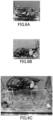
- FIG. 5A is a photograph of the front of the headlamp of Chery Tiggo 8
- FIG. 5B is a photograph of the bottom of this headlamp
- FIG. 5C is a photograph of the rear of the lamp unit according to Example 1A.
- the region enclosed by the dashed line near the sign "p" indicates the position of the opening portion connected to the discharge port of the pump
- the region enclosed by the dashed line near the sign "m” indicates the position of the opening portion covered with the gas-permeable membrane.
- a gas-permeable membrane b was used in place of the gas-permeable membrane a. Except for this, the same procedure as in Example 1A was performed to produce a lamp unit according to Example 1B.
- the permeability coefficient P of the gas-permeable membrane b was 0.00127 cm 3 /(Pa•s•cm 2 ).
- the headlamp was not connected to the pump according to the example, did not use the gas-permeable membrane a, and was hermetically sealed. Except for this, the same procedure as in Example 1A was performed to produce a lamp unit according to Comparative Example 1.
- the dried headlamp G was transferred into a thermo-hygrostat maintained in an environment with a temperature of 40°C and a relative humidity of 90% and allowed to stand for 24 hours. Thus, the humidity control process for the headlamp G was performed.
- the headlamp G was taken out of the thermo-hygrostat and left in an environment with a temperature of 20°C and a relative humidity of 65% for 1 hour. Thus, the air inside the headlamp G was displaced.
- An opening portion formed at the left end portion of the rear of the headlamp G and the discharge port of the pump according to the example were connected to each other via a flow path member that includes a polyvinyl chloride tube.
- a pressure gauge and a valve were attached to the flow path member at points along the flow path.
- FIG. 6A is a photograph of the front of the headlamp of GEELY Emgrand X7
- FIG. 6B is a photograph of the rear of this headlamp
- FIG. 6C is a photograph of the rear of the lamp unit according to Example 2A.
- the region enclosed by the dashed line near the sign “p” indicates the position of the opening portion connected to the discharge port of the pump
- the region enclosed by the dashed line near the sign “m” indicates the position of the opening portion covered with the gas-permeable membrane.
- the permeable area A of the gas-permeable membrane a was changed to 2.85 cm 2 . Except for this, the same procedure as in Example 2A was performed to produce a lamp unit according to Example 2B.
- the headlamp was not connected to the pump according to the example, did not use the gas-permeable membrane a, and was hermetically sealed. Except for this, the same procedure as in Example 2A was performed to produce a lamp unit according to Comparative Example 2.
- the dried headlamp F was transferred into a thermo-hygrostat maintained in an environment with a temperature of 40°C and a relative humidity of 90% and allowed to stand for 24 hours. Thus, the humidity control process for the headlamp F was performed.
- the headlamp F was taken out of the thermo-hygrostat and left in an environment with a temperature of 20°C and a relative humidity of 65% for 1 hour. Thus, the air inside the headlamp F was displaced.
- An opening portion formed at the lower right end portion of the rear of the headlamp F and the discharge port of the pump according to the example were connected to each other via a flow path member that includes a polyvinyl chloride tube.
- a pressure gauge was attached to the flow path member at a point along the flow path.
- FIG. 7A is a photograph of the front of the headlamp of Ford Escape
- FIG. 7B is a photograph of the rear of this headlamp
- FIG. 7C is a photograph of the rear of the lamp unit according to Example 3A.
- the region enclosed by the dashed line near the sign “p” indicates the position of the opening portion connected to the discharge port of the pump
- the region enclosed by the dashed line near the sign “m” indicates the position of the opening portion covered with the gas-permeable membrane.
- the permeable area A of the gas-permeable membrane a was changed to 10.21 cm 2 . Except for this, the same procedure as in Example 3A was performed to produce a lamp unit according to Example 3B.
- the gas-permeable membrane b was used in place of the gas-permeable membrane a, and the permeable area A of the gas-permeable membrane b was adjusted to 38.48 cm 2 . Except for this, the same procedure as in Example 3A was performed to produce a lamp unit according to Example 3C.
- the permeability coefficient P of the gas-permeable membrane b was 0.00127 cm 3 /(Pa•s•cm 2 ).
- the headlamp was not connected to the pump according to the example, did not use the gas-permeable membrane a, and was hermetically sealed. Except for this, the same procedure as in Example 3A was performed to produce a lamp unit according to Comparative Example 3.
- Ventilation performance was evaluated for the lamp units according to the examples and comparative examples.
- the lamp units produced were each placed in an environment with a temperature of 20°C and a relative humidity of 65%, and eight beam lamps were arranged in front of the lens of each lamp unit.
- the beam lamps used were the diffusing beam lamp BRF 110V 120W Type 150 manufactured by Kyokko Electric Industrial Co., Ltd.
- the distance between each lamp unit and the eight beam lamps was adjusted to approximately 700 mm.
- the eight beam lamps were lighted, and each lamp unit was illuminated with light emitted from the eight beam lamps for 2 hours.
- the temperature of the lens surface of each lamp unit increased from the start of lighting of the eight beam lamps.
- each lamp unit was warmed as described above, the evaluation of ventilation performance may employ a method for warming each lamp unit other than the method using beam lamps.
- the pump in the lamp unit was activated.
- a 90-second water pouring was performed on the lens surface of each lamp unit.
- the temperature of the water used for the water pouring was approximately 11°C.
- the lens surface was checked for the presence or absence of fogging. In the case where fogging was observed, the time T required for the fogging to be removed was measured. Additionally, in the case where no fogging was observed, the time was determined to be 0 minutes.
- the pump was activated and operated according to the following Pattern I or Pattern II.
- the pressure p inside the housing of the lamp unit during operation of the pump was read from the pressure gauge.
- the pressure p is a gauge pressure.
- Table 1 shows the pump unit used for each evaluation, the operation pattern of the pump, the pressure p [kPa] inside the housing of the lamp unit during operation of the pump, the discharge time t [s] of the pump, and the time T [min] required for fogging to be removed.
- FIG. 8 shows the relationship between the time T required for fogging to be removed and the value of 1000•p•t•P•A/V in each evaluation.
- Pattern I Operate the pump for a given discharge time t before water pouring, and stop the pump immediately before the start of water pouring.
- Pattern II Operate the pump during water pouring as well, and stop the pump 1 minute after the start of water pouring.
- a first aspect of the present invention provides a lamp unit including:
- a second aspect of the present invention provides the lamp unit according to the first aspect, further including a ventilation member for ventilation between the body housing and the external space, wherein the ventilation member is provided at the second opening portion.
- a third aspect of the present invention provides the lamp unit according to the first or second aspect, wherein the pump has a maximum discharge pressure of 0.5 to 20.0 kPa.
- a fourth aspect of the present invention provides the lamp unit according to the second aspect, wherein
- a fifth aspect of the present invention provides the lamp unit according to the second aspect, wherein the air permeability coefficient of the ventilation member is 0.00008 to 0.80293 cm 3 /(Pa•s•cm 2 ).
- a sixth aspect of the present invention provides the lamp unit according to the second aspect, wherein the permeable area of the ventilation member is 0.03142 to 50.26548 cm 2 .
- a seventh aspect of the present invention provides the lamp unit according to any one of the first to sixth aspects, wherein the spatial volume inside the lamp unit is 1000 to 20000 cm 3 .
- An eighth aspect of the present invention provides the lamp unit according to any one of the first to seventh aspects, being for a vehicle.
- a ninth aspect of the present invention provides a ventilation method for a body housing of a lamp
Landscapes
- Engineering & Computer Science (AREA)
- General Engineering & Computer Science (AREA)
- Arrangement Of Elements, Cooling, Sealing, Or The Like Of Lighting Devices (AREA)
- Non-Portable Lighting Devices Or Systems Thereof (AREA)
Applications Claiming Priority (2)
| Application Number | Priority Date | Filing Date | Title |
|---|---|---|---|
| JP2022090339A JP2023177597A (ja) | 2022-06-02 | 2022-06-02 | ランプユニット及びランプの本体筐体の換気方法 |
| PCT/JP2023/020370 WO2023234375A1 (ja) | 2022-06-02 | 2023-05-31 | ランプユニット及びランプの本体筐体の換気方法 |
Publications (2)
| Publication Number | Publication Date |
|---|---|
| EP4534893A1 true EP4534893A1 (de) | 2025-04-09 |
| EP4534893A4 EP4534893A4 (de) | 2026-01-07 |
Family
ID=89024949
Family Applications (1)
| Application Number | Title | Priority Date | Filing Date |
|---|---|---|---|
| EP23816132.7A Withdrawn EP4534893A4 (de) | 2022-06-02 | 2023-05-31 | Lampeneinheit und verfahren zur belüftung des körpergehäuses der lampe |
Country Status (5)
| Country | Link |
|---|---|
| EP (1) | EP4534893A4 (de) |
| JP (1) | JP2023177597A (de) |
| KR (1) | KR20250016302A (de) |
| CN (1) | CN119137411A (de) |
| WO (1) | WO2023234375A1 (de) |
Families Citing this family (1)
| Publication number | Priority date | Publication date | Assignee | Title |
|---|---|---|---|---|
| JP7607814B1 (ja) * | 2024-02-29 | 2024-12-27 | 川村 敬一 | 車載機器の通気構造 |
Family Cites Families (9)
| Publication number | Priority date | Publication date | Assignee | Title |
|---|---|---|---|---|
| JPH077004U (ja) * | 1993-06-30 | 1995-01-31 | 市光工業株式会社 | 車両用灯具 |
| JP2006334537A (ja) * | 2005-06-03 | 2006-12-14 | Nitto Denko Corp | 通気部材および通気部材キットならびにこれらを用いた通気筐体および通気タンク |
| JP6068886B2 (ja) * | 2012-03-30 | 2017-01-25 | 日東電工株式会社 | 換気システム |
| KR20160014452A (ko) * | 2014-07-29 | 2016-02-11 | 현대모비스 주식회사 | 차량용 헤드램프 |
| JP6803130B2 (ja) * | 2014-11-19 | 2020-12-23 | 日東電工株式会社 | ランプ |
| JP2018045879A (ja) | 2016-09-14 | 2018-03-22 | 株式会社小糸製作所 | 車両用灯具 |
| CN107917404A (zh) * | 2017-10-18 | 2018-04-17 | 浙江零跑科技有限公司 | 一种汽车前照灯降温、防雾系统及该车灯系统的车辆 |
| CN212029406U (zh) * | 2020-06-15 | 2020-11-27 | 姚乐淑 | 汽车灯具 |
| CN114001324A (zh) * | 2020-07-28 | 2022-02-01 | 浙江金业汽车部件有限公司 | 不起雾的汽车灯具 |
-
2022
- 2022-06-02 JP JP2022090339A patent/JP2023177597A/ja active Pending
-
2023
- 2023-05-31 KR KR1020247042968A patent/KR20250016302A/ko active Pending
- 2023-05-31 EP EP23816132.7A patent/EP4534893A4/de not_active Withdrawn
- 2023-05-31 CN CN202380040234.6A patent/CN119137411A/zh active Pending
- 2023-05-31 WO PCT/JP2023/020370 patent/WO2023234375A1/ja not_active Ceased
Also Published As
| Publication number | Publication date |
|---|---|
| CN119137411A (zh) | 2024-12-13 |
| EP4534893A4 (de) | 2026-01-07 |
| KR20250016302A (ko) | 2025-02-03 |
| JP2023177597A (ja) | 2023-12-14 |
| WO2023234375A1 (ja) | 2023-12-07 |
Similar Documents
| Publication | Publication Date | Title |
|---|---|---|
| CN101189058B (zh) | 透气构件和配套透气构件以及使用它们的透气壳体和透气容器 | |
| EP2833706A1 (de) | Belüftungssystem | |
| EP4534893A1 (de) | Lampeneinheit und verfahren zur belüftung des körpergehäuses der lampe | |
| JP6928078B2 (ja) | チェックバルブ | |
| KR101244582B1 (ko) | 통기 부재와 이것을 이용한 통기 하우징 | |
| JP4276246B2 (ja) | 閉鎖されたランプハウジング内の通気装置 | |
| EP2583733B1 (de) | Wasserdichter und luftdurchlässiger filter und seine verwendung | |
| CN105814359B (zh) | 车辆用灯具 | |
| KR102058425B1 (ko) | 제습용 더스트 커버 | |
| CN108370648A (zh) | 透气调湿单元及设备 | |
| WO2000047932A9 (en) | Headlight assembly humidity control system | |
| WO2000047932A1 (en) | Headlight assembly humidity control system | |
| CN218565274U (zh) | 一种防止车灯流挂并且降低车灯雾气的透气阀组件 | |
| JP4498996B2 (ja) | 筐体の通気構造 | |
| WO2017187544A1 (ja) | Ptfeフィルムを用いた成形体フィルター、及びそれを用いた医療吸引器用ディスポーザブルバッグまたは容器 | |
| CN110410751A (zh) | 一种红外可逆干燥剂组件及应用 | |
| WO2020085211A1 (ja) | 通気部品 | |
| KR102281021B1 (ko) | 자동차 헤드라이트 결로방지 제습제 및 제습제품 | |
| JP2963173B2 (ja) | ランプ | |
| JPH01279502A (ja) | 車両用灯具 | |
| CN121623528A (zh) | 一种模块化干燥除雾装置 | |
| WO2026042330A1 (ja) | 紫外光照射装置 | |
| JP2001267063A (ja) | エレクトロルミネッセンス素子用部材およびそれを内蔵したエレクトロルミネッセンス素子 |
Legal Events
| Date | Code | Title | Description |
|---|---|---|---|
| STAA | Information on the status of an ep patent application or granted ep patent |
Free format text: STATUS: THE INTERNATIONAL PUBLICATION HAS BEEN MADE |
|
| PUAI | Public reference made under article 153(3) epc to a published international application that has entered the european phase |
Free format text: ORIGINAL CODE: 0009012 |
|
| STAA | Information on the status of an ep patent application or granted ep patent |
Free format text: STATUS: REQUEST FOR EXAMINATION WAS MADE |
|
| 17P | Request for examination filed |
Effective date: 20241205 |
|
| AK | Designated contracting states |
Kind code of ref document: A1 Designated state(s): AL AT BE BG CH CY CZ DE DK EE ES FI FR GB GR HR HU IE IS IT LI LT LU LV MC ME MK MT NL NO PL PT RO RS SE SI SK SM TR |
|
| DAV | Request for validation of the european patent (deleted) | ||
| DAX | Request for extension of the european patent (deleted) | ||
| A4 | Supplementary search report drawn up and despatched |
Effective date: 20251205 |
|
| RIC1 | Information provided on ipc code assigned before grant |
Ipc: F21S 45/30 20180101AFI20251201BHEP Ipc: F21V 15/01 20060101ALI20251201BHEP Ipc: F21V 31/03 20060101ALI20251201BHEP Ipc: F21W 102/00 20180101ALI20251201BHEP Ipc: F21Y 101/00 20160101ALI20251201BHEP Ipc: F21Y 115/10 20160101ALI20251201BHEP Ipc: F21S 45/20 20180101ALI20251201BHEP Ipc: F21S 45/33 20180101ALI20251201BHEP |
|
| STAA | Information on the status of an ep patent application or granted ep patent |
Free format text: STATUS: THE APPLICATION HAS BEEN WITHDRAWN |
|
| 18W | Application withdrawn |
Effective date: 20260122 |