EP4534876A1 - Ventile für ladungsträgerstrahlmikroskop, ventilelement und ladungsträgerstrahlmikroskop - Google Patents
Ventile für ladungsträgerstrahlmikroskop, ventilelement und ladungsträgerstrahlmikroskop Download PDFInfo
- Publication number
- EP4534876A1 EP4534876A1 EP24189127.4A EP24189127A EP4534876A1 EP 4534876 A1 EP4534876 A1 EP 4534876A1 EP 24189127 A EP24189127 A EP 24189127A EP 4534876 A1 EP4534876 A1 EP 4534876A1
- Authority
- EP
- European Patent Office
- Prior art keywords
- valve
- valve member
- opening
- sealing ring
- charged particle
- Prior art date
- Legal status (The legal status is an assumption and is not a legal conclusion. Google has not performed a legal analysis and makes no representation as to the accuracy of the status listed.)
- Pending
Links
Images


Classifications
-
- F—MECHANICAL ENGINEERING; LIGHTING; HEATING; WEAPONS; BLASTING
- F16—ENGINEERING ELEMENTS AND UNITS; GENERAL MEASURES FOR PRODUCING AND MAINTAINING EFFECTIVE FUNCTIONING OF MACHINES OR INSTALLATIONS; THERMAL INSULATION IN GENERAL
- F16K—VALVES; TAPS; COCKS; ACTUATING-FLOATS; DEVICES FOR VENTING OR AERATING
- F16K3/00—Gate valves or sliding valves, i.e. cut-off apparatus with closing members having a sliding movement along the seat for opening and closing
- F16K3/02—Gate valves or sliding valves, i.e. cut-off apparatus with closing members having a sliding movement along the seat for opening and closing with flat sealing faces; Packings therefor
- F16K3/0218—Gate valves or sliding valves, i.e. cut-off apparatus with closing members having a sliding movement along the seat for opening and closing with flat sealing faces; Packings therefor with only one sealing face
-
- F—MECHANICAL ENGINEERING; LIGHTING; HEATING; WEAPONS; BLASTING
- F16—ENGINEERING ELEMENTS AND UNITS; GENERAL MEASURES FOR PRODUCING AND MAINTAINING EFFECTIVE FUNCTIONING OF MACHINES OR INSTALLATIONS; THERMAL INSULATION IN GENERAL
- F16K—VALVES; TAPS; COCKS; ACTUATING-FLOATS; DEVICES FOR VENTING OR AERATING
- F16K3/00—Gate valves or sliding valves, i.e. cut-off apparatus with closing members having a sliding movement along the seat for opening and closing
- F16K3/02—Gate valves or sliding valves, i.e. cut-off apparatus with closing members having a sliding movement along the seat for opening and closing with flat sealing faces; Packings therefor
- F16K3/16—Gate valves or sliding valves, i.e. cut-off apparatus with closing members having a sliding movement along the seat for opening and closing with flat sealing faces; Packings therefor with special arrangements for separating the sealing faces or for pressing them together
- F16K3/18—Gate valves or sliding valves, i.e. cut-off apparatus with closing members having a sliding movement along the seat for opening and closing with flat sealing faces; Packings therefor with special arrangements for separating the sealing faces or for pressing them together by movement of the closure members
-
- F—MECHANICAL ENGINEERING; LIGHTING; HEATING; WEAPONS; BLASTING
- F16—ENGINEERING ELEMENTS AND UNITS; GENERAL MEASURES FOR PRODUCING AND MAINTAINING EFFECTIVE FUNCTIONING OF MACHINES OR INSTALLATIONS; THERMAL INSULATION IN GENERAL
- F16K—VALVES; TAPS; COCKS; ACTUATING-FLOATS; DEVICES FOR VENTING OR AERATING
- F16K51/00—Other details not peculiar to particular types of valves or cut-off apparatus
- F16K51/02—Other details not peculiar to particular types of valves or cut-off apparatus specially adapted for high-vacuum installations
-
- H—ELECTRICITY
- H01—ELECTRIC ELEMENTS
- H01J—ELECTRIC DISCHARGE TUBES OR DISCHARGE LAMPS
- H01J37/00—Discharge tubes with provision for introducing objects or material to be exposed to the discharge, e.g. for the purpose of examination or processing thereof
- H01J37/02—Details
- H01J37/04—Arrangements of electrodes and associated parts for generating or controlling the discharge, e.g. electron-optical arrangement or ion-optical arrangement
- H01J37/09—Diaphragms; Shields associated with electron or ion-optical arrangements; Compensation of disturbing fields
-
- H—ELECTRICITY
- H01—ELECTRIC ELEMENTS
- H01J—ELECTRIC DISCHARGE TUBES OR DISCHARGE LAMPS
- H01J37/00—Discharge tubes with provision for introducing objects or material to be exposed to the discharge, e.g. for the purpose of examination or processing thereof
- H01J37/02—Details
- H01J37/18—Vacuum locks ; Means for obtaining or maintaining the desired pressure within the vessel
-
- H—ELECTRICITY
- H01—ELECTRIC ELEMENTS
- H01J—ELECTRIC DISCHARGE TUBES OR DISCHARGE LAMPS
- H01J2237/00—Discharge tubes exposing object to beam, e.g. for analysis treatment, etching, imaging
- H01J2237/18—Vacuum control means
- H01J2237/186—Valves
Definitions
- the present application relates to valves for charged particle beam microscopes, valve members of such valves and to corresponding charged particle beam microscopes
- Charged particle beam microscopes are a type of microscopes where a charged particle beam, for example an electron beam or an ion beam, is guided to a sample, and the interaction between the charged particle beam and the sample is used for generating an image.
- Examples for charged partial beam microscopes are transmission electron microscopes (TEMs) and scanning electron microscopes (SEM).
- TEMs transmission electron microscopes
- SEM scanning electron microscopes
- MSEM Multi-SEMs
- the charged particle beam is at least for the most part guided through a vacuum onto the sample.
- a vacuum usually an ultra high vacuum (UHV) is used (1 ⁇ 10 -9 mbar or better), while in other parts the beam passes through a high vacuum (e.g. 1 ⁇ 10 -6 mbar or better) is sufficient.
- UHV ultra high vacuum
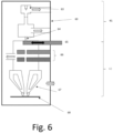
- a valve is used in some configurations to separate a first part where the charged particle beam is generated from a second chamber where the sample resides.
- the charged particle beam is focused onto a sample 68 via an objective lens 67.
- Detectors 66 serve for detecting the signal, e.g. scattered particles, secondary particles and/or radiation, as mentioned above.
- the pressure again may be higher than in lower stage 62, e.g. 1 ⁇ 10 -5 mbar or less. It should be noted that pressures here are given only by way of example and may vary depending on the implementation.
- valve 65 is provided which may be used to separate upper chamber 61 from lower chamber 62. For example, in case of a loss of vacuum in lower chamber 62, valve 65 may be closed, to preserve the vacuum in upper chamber 61 and protect cathode 63. Also, when charged particle beam microscope is not in use or when the sample is changed, valve 65 may be closed.
- the present application generally relates to such valves which may be used in charged particle beam microscopes to separate areas from each other in a gas-tight manner, for example upper chamber 61 and lower chamber 62 of Fig. 6 .
- Other parts of such charged particle beam microscopes may be implemented in any conventional manner, and Fig. 6 shows merely a simple non-limiting example.
- the shielding member may prevent a charging of the sealing ring in the second position.
- the second position may be offset from the first position in a direction parallel to a plane in which the opening is provided.
- the sealing member may for example be made of a metal.
- the shielding member may extend to a height at least corresponding to a height of the sealing ring above the first surface in the second position. In some embodiments, this may provide a good shielding of the sealing ring.
- the sealing ring may for example be an O-ring made of a rubber material.
- the shielding member may be attached to the second surface of the valve member body opposite the first surface. In some embodiments, this may give some resiliency to the arrangement of the shielding member coupled to the valve member body.
- the valve may further comprise a valve housing member which extends below the valve member.
- the shielding member may be configured to electrically contact at least a conducting part of the valve housing member in the second position. This may allow for a biasing of the valve member in the second position via the valve housing member and for shielding member.
- the valve housing member may be configured to be set to a high voltage potential at least when the valve member is in the second position, such that the valve member is biased with the high voltage potential in the second position via the shielding member.
- the shielding member may be configured to electrically contact a conducting portion of the valve seat when the valve member is in the first position. In this way, in the first position the valve member may be biased via the valve seat, for example to a ground potential if the valve seat is configured to be set to a ground potential at least when the valve is in the first position.
- valve member may include an electrical contact spring at a further side surface thereof, which is configured to receive a first voltage in the first position and a second voltage in the second position, for example the high voltage and ground potential mentioned above.
- the first voltage may be a high voltage
- the second voltage may correspond to ground.
- the valve seat may comprise a further shielding member around the opening, where the sealing ring is configured to abut against the further shielding member in the first position and shielded by the shielding member in the second position.
- This further shielding member in some embodiments may provide an additional shielding for the sealing ring.
- This further shielding member may also be used independently from the shielding member, such that in a second aspect a valve for a charged particle beam microscope is provided, comprising: a valve seat comprising an opening, and a shielding member around the opening, and a valve member comprising a valve member body and a sealing ring on the first surface of the valve member body, wherein the valve member is movable between a first position where the sealing ring abuts against the shielding member to seal around the opening and a second position where the valve member is spaced for apart from the opening and the sealing ring is shielded by the shielding member.
- the valve may further comprise a flexible electrically conducting wire coupled to the valve member body, via which the valve member may be biased, for example to the first and/or second voltage mentioned above.
- a flexible electrically conducting wire coupled to the valve member body, via which the valve member may be biased, for example to the first and/or second voltage mentioned above.
- an electrical contact may be provided adjacent to the valve seat, such that the valve member contacts the electrical contact in the second position. This also serves for biasing the valve member in the second position and may also be used independently from some of the features above.
- the electrical contact may form part of a recess where the valve member is positioned when in the second position.
- a suitable vacuum compatible lubricant may be provided at portions where the valve member comes to sliding contact with other parts like the valve housing member.
- the lubricant may be provided where the shielding member electrically contacts a conducting part of the valve housing member or where the electrical contact spring at the further side surface comes into contact with other elements.
- the lubricant may be based on a fluoropolymer or a silicone grease.
- the lubricant may be highly inert, i.e. not prone to entering chemical reactions, and therefore in some embodiments may also protect against corrosion.
- suitable lubricants may be based on polyfluoroethylene (PFE) with a viscosity of the order of 250-300 mm 2 /s at 20°C, a TOC (degassing) value of at or below 20ng/mg when at 200°C for 2min as analyzed by GC-MS (combine gas chromatography and mass spectrometry).
- PFE polyfluoroethylene
- TOC degassing
- valve for a charged particle beam microscope comprising:
- valve members are provided.
- a charged particle beam microscope comprising any of the valves discussed above is provided.
- valves and valve members for charged particle beam microscopes will be discussed.
- the valves and valve members discussed may in particular separate a first chamber where a charged particle beam like an electron beam is generated from a second chamber where the sample is provided, for example to preserve a vacuum.
- the valves discussed may be used as valve 65 in the charged particle beam microscope of Fig. 6 described above.
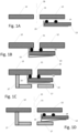
- Fig. 1A is a side view of a valve according to an embodiment in an open position
- Fig. 1B is a side view of the valve of Fig. 1A in a closed position
- Figures 1E and 1F show perspective views of example implementations of the valve of Figures 1A and 1B .
- valve of Figures 1A, 1B include a valve seat 12 with an opening 11.
- a charged particle beam 16 for example an electron beam, passes through opening 11.
- the valve further comprises a valve member including a valve member body 13, a sealing ring 14 disposed on a first side of the valve member body 13, and a shielding 15.
- a valve member including a valve member body 13, a sealing ring 14 disposed on a first side of the valve member body 13, and a shielding 15.
- sealing ring 14 seals around opening 11, for example to prevent a vacuum loss.
- shielding 15 may be attached to second side of valve member body 13 opposite the first side (where sealing ring 14 is provided), such that shielding member 15 is fixed in a spring-like manner.
- shielding member 15 In the closed position of Fig. 1B , as shown shielding member 15 then abuts against valve seat 12 and establishes an electrical contact to valve seat 12.
- Valve seat 12 in the closed position may for example be set to a ground potential, and this contact of shielding member 15 to valve seat 12 contributes to also setting the valve member to ground potential.
- in the open position shielding member 15 may press against valve housing member 17, such that in the open position shielding member 15 may be biased via valve housing member 17, for example to a high voltage potential.
- in the open position shielding member 15 is not in contact with valve housing member 17 in the open position.
- valve member of Fig. 1E and 1F has an electrical spring contact 18 at a side thereof, which in the embodiment of Figures 1E and 1F is formed with shielding member 15 in one piece. In other embodiments, an implementation using separate pieces or elements for shielding member 15 may be used. Electrical spring contact 18 serves to additionally provide the conventional contacting for biasing the valve member, as explained in the introductory portion with respect to Figures 5C and 5D, see electrical spring contact 18 thereof. In this case, the biasing via shielding member 15 as shown in Figures 1B, 1C for the contact to the valve seat and in Fig. 1D for the contact to valve housing member 17 provides an additional contact to the conventional contact via electrical spring contact 18.
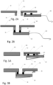
- Figures 2A and 2B illustrate a valve according to a further embodiment, where Fig. 2A shows the open case where the valve member is in the second position, and Fig. 2B shows the closed case where opening 11 is sealed.
- a further shielding 21 is provided which extends from valve seat 12 and surrounds opening 11.
- further shielding 21 is interposed between the sealing ring 14 and the charged particle beam 16, such that a charging of sealing ring 14 is prevented or at least reduced.
- sealing ring 14 abuts against further shielding 21, thus sealing opening 11.
- further shielding 21 may be combined with shielding 15 discussed previously.
- Fig. 3A and 3B illustrate a valve according to a further embodiment.
- Fig. 3A shows the second position (open position)
- Fig. 3B shows the first position (close position).
- a valve seat 32 which has a recess 31, into which sealing ring 14 is positioned in the open case of Fig. 3A , such that sealing ring 14 is shielded from charged particle beam 16.
- an electrically conducting element 33 is provided, against which valve member body 13 abuts in the second position, thus providing an electrical contact for biasing the valve member.
- shielding member 15 is provided and has the function as explained with reference to Figures 1A-1K, in particular abuts against valve seat 32 in the first position of Fig. 3B where the sealing ring 14 is pressed against valve seat 32 to seal around opening 11. Nevertheless, the recess and the electrical contact element 33 of Figures 3A and 3B may be provided independently from shielding member 15.
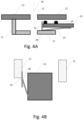
- a lubricant is used at points where a sliding electrical contact is established. This is illustrated in Figures 4A and 4B.
- Fig. 4A reproduces Fig. 1D .
- Reference numeral 40 indicates where shielding member 15 comes into sliding contact with valve housing member 17, which may correspond to the contact established by protrusion 19, as shown in Figures 1H and 1J.
- Fig. 4B shows a top view where electrical spring contact 18 comes into contact with valve housing member 17 or any other point, and as indicated by reference numeral 41 here also a lubricant may be used.
- the lubricant may protect from mechanical abrasion and generation of particles.
- Such an abrasion besides problems which may generated by free particles in the charged particle beam microscope itself, may increase the surface of the corresponding contact elements like electrical spring contact 18 or shielding member 15, which in turn may increase an oxidation or other chemical reaction, which may reduce the quality of the electrical contact.
- shielding 15 may be made of copper, bronze, or brass (like chromed brass), and in charged particle beam microscope NOCI gas may react with such metal to form copper chloride, which may provide an electrical isolation.Such NOCl gas is used as processing gas to locally etch structures in the samples by means of the electron beam, but may also inadvertedly react with other components in the device.
- Suitable lubricants include fluoropolymers like so called TEM oil., or silicone grease based lubricants. [Examples include APIEZON ® high vacuum grease or silicone high vacuum grease by Plano GmbH, or Lit-Oil 300 or 500 oils from the Zeiss Material catalog.
- various embodiments herein may increase the reliability of biasing of the valve member and/or may provide a shielding for a sealing ring, which may in some embodiments prevent or mitigate a deterioration of image quality or image position drift of the charged particle beam microscope.
Landscapes
- Engineering & Computer Science (AREA)
- General Engineering & Computer Science (AREA)
- Chemical & Material Sciences (AREA)
- Analytical Chemistry (AREA)
- Mechanical Engineering (AREA)
- Sliding Valves (AREA)
- Lift Valve (AREA)
- Details Of Valves (AREA)
- Analysing Materials By The Use Of Radiation (AREA)
Applications Claiming Priority (1)
| Application Number | Priority Date | Filing Date | Title |
|---|---|---|---|
| DE102023118986 | 2023-07-18 |
Publications (1)
| Publication Number | Publication Date |
|---|---|
| EP4534876A1 true EP4534876A1 (de) | 2025-04-09 |
Family
ID=91958913
Family Applications (1)
| Application Number | Title | Priority Date | Filing Date |
|---|---|---|---|
| EP24189127.4A Pending EP4534876A1 (de) | 2023-07-18 | 2024-07-17 | Ventile für ladungsträgerstrahlmikroskop, ventilelement und ladungsträgerstrahlmikroskop |
Country Status (4)
| Country | Link |
|---|---|
| US (1) | US20250029808A1 (de) |
| EP (1) | EP4534876A1 (de) |
| JP (1) | JP2025020087A (de) |
| TW (1) | TW202509986A (de) |
Citations (6)
| Publication number | Priority date | Publication date | Assignee | Title |
|---|---|---|---|---|
| JP2008293773A (ja) * | 2007-05-24 | 2008-12-04 | Jeol Ltd | 荷電粒子ビーム装置 |
| US20150228449A1 (en) * | 2012-10-01 | 2015-08-13 | Hitachi High-Technologies Corporation | Charged Particle Beam Device, Position Adjusting Method for Diaphragm, and Diaphragm Position Adjusting Jig |
| US10290522B2 (en) * | 2013-05-30 | 2019-05-14 | Hitachi High-Technologies Corporation | Conductive interface system between vacuum chambers in a charged particle beam device |
| US20220375732A1 (en) * | 2021-05-18 | 2022-11-24 | Vat Holding Ag | High-frequency grounding device and vacuum valve having high-frequency grounding device |
| EP4131326A1 (de) * | 2020-03-26 | 2023-02-08 | National Institute for Materials Science | Elektronenkanonenkammer für ein rasterelektronenmikroskop, elektronenkanone damit und rasterelektronenmikroskop |
| EP4206643A1 (de) * | 2021-12-30 | 2023-07-05 | Fei Company | Verfahren und vorrichtung zur herstellung einer probe eines oder mehrerer moleküle zur bildgebung mit einem kryoelektronenmikroskop |
-
2024
- 2024-07-04 TW TW113125120A patent/TW202509986A/zh unknown
- 2024-07-08 JP JP2024109713A patent/JP2025020087A/ja active Pending
- 2024-07-12 US US18/771,293 patent/US20250029808A1/en active Pending
- 2024-07-17 EP EP24189127.4A patent/EP4534876A1/de active Pending
Patent Citations (6)
| Publication number | Priority date | Publication date | Assignee | Title |
|---|---|---|---|---|
| JP2008293773A (ja) * | 2007-05-24 | 2008-12-04 | Jeol Ltd | 荷電粒子ビーム装置 |
| US20150228449A1 (en) * | 2012-10-01 | 2015-08-13 | Hitachi High-Technologies Corporation | Charged Particle Beam Device, Position Adjusting Method for Diaphragm, and Diaphragm Position Adjusting Jig |
| US10290522B2 (en) * | 2013-05-30 | 2019-05-14 | Hitachi High-Technologies Corporation | Conductive interface system between vacuum chambers in a charged particle beam device |
| EP4131326A1 (de) * | 2020-03-26 | 2023-02-08 | National Institute for Materials Science | Elektronenkanonenkammer für ein rasterelektronenmikroskop, elektronenkanone damit und rasterelektronenmikroskop |
| US20220375732A1 (en) * | 2021-05-18 | 2022-11-24 | Vat Holding Ag | High-frequency grounding device and vacuum valve having high-frequency grounding device |
| EP4206643A1 (de) * | 2021-12-30 | 2023-07-05 | Fei Company | Verfahren und vorrichtung zur herstellung einer probe eines oder mehrerer moleküle zur bildgebung mit einem kryoelektronenmikroskop |
Also Published As
| Publication number | Publication date |
|---|---|
| TW202509986A (zh) | 2025-03-01 |
| US20250029808A1 (en) | 2025-01-23 |
| JP2025020087A (ja) | 2025-02-12 |
Similar Documents
| Publication | Publication Date | Title |
|---|---|---|
| US6816574B2 (en) | X-ray tube high voltage connector | |
| US8598524B2 (en) | Slider bearing for use with an apparatus comprising a vacuum chamber | |
| US20200058462A1 (en) | X-ray tube and x-ray generation device | |
| US9099276B1 (en) | High-voltage energy-dispersive spectroscopy using a low-voltage scanning electron microscope | |
| EP4534876A1 (de) | Ventile für ladungsträgerstrahlmikroskop, ventilelement und ladungsträgerstrahlmikroskop | |
| US5026995A (en) | Particle beam surface analyzer | |
| US9666404B2 (en) | Charged particle source arrangement for a charged particle beam device, charged particle beam device for sample inspection, and method for providing a primary charged particle beam for sample inspection in a charged particle beam | |
| JP5648114B1 (ja) | 試料の表面観察に用いられる試料ホルダー及びその制御方法 | |
| EP0617452B1 (de) | Ladungsträger Analysator | |
| US6630667B1 (en) | Compact, high collection efficiency scintillator for secondary electron detection | |
| US20240250469A1 (en) | Hydraulic electrical connector assembly | |
| US8502163B2 (en) | Charged particle beam device, vacuum valve therefor and operation thereof | |
| US4739133A (en) | Electrical switching apparatus | |
| Kurihara | Low-aberration einzel lens for a focused-ion-beam system | |
| GB2174550A (en) | Vacuum devices | |
| CN114188201B (zh) | 电极布置、用于电极布置的接触组件、带电粒子束装置和减小电极布置中的电场强度的方法 | |
| US11469072B2 (en) | Charged particle beam apparatus, scanning electron microscope, and method of operating a charged particle beam apparatus | |
| EP4576149A2 (de) | Elektrisches verbindungssystem | |
| US12412713B2 (en) | Contact assembly | |
| JP5828056B1 (ja) | マルチ断面観察ホルダー | |
| Turner | Electron microscope techniques for surface characterization | |
| JPH11176369A (ja) | 真空装置における電気絶縁構造 |
Legal Events
| Date | Code | Title | Description |
|---|---|---|---|
| PUAI | Public reference made under article 153(3) epc to a published international application that has entered the european phase |
Free format text: ORIGINAL CODE: 0009012 |
|
| STAA | Information on the status of an ep patent application or granted ep patent |
Free format text: STATUS: THE APPLICATION HAS BEEN PUBLISHED |
|
| AK | Designated contracting states |
Kind code of ref document: A1 Designated state(s): AL AT BE BG CH CY CZ DE DK EE ES FI FR GB GR HR HU IE IS IT LI LT LU LV MC ME MK MT NL NO PL PT RO RS SE SI SK SM TR |
|
| STAA | Information on the status of an ep patent application or granted ep patent |
Free format text: STATUS: THE APPLICATION IS DEEMED TO BE WITHDRAWN |