EP4534860A2 - Kupplungssysteme - Google Patents
Kupplungssysteme Download PDFInfo
- Publication number
- EP4534860A2 EP4534860A2 EP25160098.7A EP25160098A EP4534860A2 EP 4534860 A2 EP4534860 A2 EP 4534860A2 EP 25160098 A EP25160098 A EP 25160098A EP 4534860 A2 EP4534860 A2 EP 4534860A2
- Authority
- EP
- European Patent Office
- Prior art keywords
- securing apparatus
- support member
- release
- mobile equipment
- base
- Prior art date
- Legal status (The legal status is an assumption and is not a legal conclusion. Google has not performed a legal analysis and makes no representation as to the accuracy of the status listed.)
- Pending
Links
Images


Classifications
-
- A—HUMAN NECESSITIES
- A61—MEDICAL OR VETERINARY SCIENCE; HYGIENE
- A61M—DEVICES FOR INTRODUCING MEDIA INTO, OR ONTO, THE BODY; DEVICES FOR TRANSDUCING BODY MEDIA OR FOR TAKING MEDIA FROM THE BODY; DEVICES FOR PRODUCING OR ENDING SLEEP OR STUPOR
- A61M5/00—Devices for bringing media into the body in a subcutaneous, intra-vascular or intramuscular way; Accessories therefor, e.g. filling or cleaning devices, arm-rests
- A61M5/14—Infusion devices, e.g. infusing by gravity; Blood infusion; Accessories therefor
- A61M5/1414—Hanging-up devices
- A61M5/1415—Stands, brackets or the like for supporting infusion accessories
-
- F—MECHANICAL ENGINEERING; LIGHTING; HEATING; WEAPONS; BLASTING
- F16—ENGINEERING ELEMENTS AND UNITS; GENERAL MEASURES FOR PRODUCING AND MAINTAINING EFFECTIVE FUNCTIONING OF MACHINES OR INSTALLATIONS; THERMAL INSULATION IN GENERAL
- F16M—FRAMES, CASINGS OR BEDS OF ENGINES, MACHINES OR APPARATUS, NOT SPECIFIC TO ENGINES, MACHINES OR APPARATUS PROVIDED FOR ELSEWHERE; STANDS; SUPPORTS
- F16M11/00—Stands or trestles as supports for apparatus or articles placed thereon ; Stands for scientific apparatus such as gravitational force meters
- F16M11/02—Heads
- F16M11/04—Means for attachment of apparatus; Means allowing adjustment of the apparatus relatively to the stand
- F16M11/041—Allowing quick release of the apparatus
-
- F—MECHANICAL ENGINEERING; LIGHTING; HEATING; WEAPONS; BLASTING
- F16—ENGINEERING ELEMENTS AND UNITS; GENERAL MEASURES FOR PRODUCING AND MAINTAINING EFFECTIVE FUNCTIONING OF MACHINES OR INSTALLATIONS; THERMAL INSULATION IN GENERAL
- F16B—DEVICES FOR FASTENING OR SECURING CONSTRUCTIONAL ELEMENTS OR MACHINE PARTS TOGETHER, e.g. NAILS, BOLTS, CIRCLIPS, CLAMPS, CLIPS OR WEDGES; JOINTS OR JOINTING
- F16B2/00—Friction-grip releasable fastenings
- F16B2/02—Clamps, i.e. with gripping action effected by positive means other than the inherent resistance to deformation of the material of the fastening
- F16B2/06—Clamps, i.e. with gripping action effected by positive means other than the inherent resistance to deformation of the material of the fastening external, i.e. with contracting action
- F16B2/10—Clamps, i.e. with gripping action effected by positive means other than the inherent resistance to deformation of the material of the fastening external, i.e. with contracting action using pivoting jaws
-
- F—MECHANICAL ENGINEERING; LIGHTING; HEATING; WEAPONS; BLASTING
- F16—ENGINEERING ELEMENTS AND UNITS; GENERAL MEASURES FOR PRODUCING AND MAINTAINING EFFECTIVE FUNCTIONING OF MACHINES OR INSTALLATIONS; THERMAL INSULATION IN GENERAL
- F16M—FRAMES, CASINGS OR BEDS OF ENGINES, MACHINES OR APPARATUS, NOT SPECIFIC TO ENGINES, MACHINES OR APPARATUS PROVIDED FOR ELSEWHERE; STANDS; SUPPORTS
- F16M13/00—Other supports for positioning apparatus or articles; Means for steadying hand-held apparatus or articles
- F16M13/02—Other supports for positioning apparatus or articles; Means for steadying hand-held apparatus or articles for supporting on, or attaching to, an object, e.g. tree, gate, window-frame, cycle
- F16M13/022—Other supports for positioning apparatus or articles; Means for steadying hand-held apparatus or articles for supporting on, or attaching to, an object, e.g. tree, gate, window-frame, cycle repositionable
-
- B—PERFORMING OPERATIONS; TRANSPORTING
- B60—VEHICLES IN GENERAL
- B60P—VEHICLES ADAPTED FOR LOAD TRANSPORTATION OR TO TRANSPORT, TO CARRY, OR TO COMPRISE SPECIAL LOADS OR OBJECTS
- B60P7/00—Securing or covering of load on vehicles
- B60P7/06—Securing of load
- B60P7/08—Securing to the vehicle floor or sides
- B60P7/0807—Attachment points
- B60P7/0815—Attachment rails or trellis
-
- F—MECHANICAL ENGINEERING; LIGHTING; HEATING; WEAPONS; BLASTING
- F16—ENGINEERING ELEMENTS AND UNITS; GENERAL MEASURES FOR PRODUCING AND MAINTAINING EFFECTIVE FUNCTIONING OF MACHINES OR INSTALLATIONS; THERMAL INSULATION IN GENERAL
- F16B—DEVICES FOR FASTENING OR SECURING CONSTRUCTIONAL ELEMENTS OR MACHINE PARTS TOGETHER, e.g. NAILS, BOLTS, CIRCLIPS, CLAMPS, CLIPS OR WEDGES; JOINTS OR JOINTING
- F16B2/00—Friction-grip releasable fastenings
- F16B2/02—Clamps, i.e. with gripping action effected by positive means other than the inherent resistance to deformation of the material of the fastening
- F16B2/06—Clamps, i.e. with gripping action effected by positive means other than the inherent resistance to deformation of the material of the fastening external, i.e. with contracting action
- F16B2/12—Clamps, i.e. with gripping action effected by positive means other than the inherent resistance to deformation of the material of the fastening external, i.e. with contracting action using sliding jaws
-
- F—MECHANICAL ENGINEERING; LIGHTING; HEATING; WEAPONS; BLASTING
- F16—ENGINEERING ELEMENTS AND UNITS; GENERAL MEASURES FOR PRODUCING AND MAINTAINING EFFECTIVE FUNCTIONING OF MACHINES OR INSTALLATIONS; THERMAL INSULATION IN GENERAL
- F16B—DEVICES FOR FASTENING OR SECURING CONSTRUCTIONAL ELEMENTS OR MACHINE PARTS TOGETHER, e.g. NAILS, BOLTS, CIRCLIPS, CLAMPS, CLIPS OR WEDGES; JOINTS OR JOINTING
- F16B5/00—Joining sheets or plates, e.g. panels, to one another or to strips or bars parallel to them
- F16B5/06—Joining sheets or plates, e.g. panels, to one another or to strips or bars parallel to them by means of clamps or clips
- F16B5/0607—Joining sheets or plates, e.g. panels, to one another or to strips or bars parallel to them by means of clamps or clips joining sheets or plates to each other
- F16B5/0621—Joining sheets or plates, e.g. panels, to one another or to strips or bars parallel to them by means of clamps or clips joining sheets or plates to each other in parallel relationship
- F16B5/0657—Joining sheets or plates, e.g. panels, to one another or to strips or bars parallel to them by means of clamps or clips joining sheets or plates to each other in parallel relationship at least one of the plates providing a raised structure, e.g. of the doghouse type, for connection with the clamps or clips of the other plate
-
- F—MECHANICAL ENGINEERING; LIGHTING; HEATING; WEAPONS; BLASTING
- F16—ENGINEERING ELEMENTS AND UNITS; GENERAL MEASURES FOR PRODUCING AND MAINTAINING EFFECTIVE FUNCTIONING OF MACHINES OR INSTALLATIONS; THERMAL INSULATION IN GENERAL
- F16B—DEVICES FOR FASTENING OR SECURING CONSTRUCTIONAL ELEMENTS OR MACHINE PARTS TOGETHER, e.g. NAILS, BOLTS, CIRCLIPS, CLAMPS, CLIPS OR WEDGES; JOINTS OR JOINTING
- F16B5/00—Joining sheets or plates, e.g. panels, to one another or to strips or bars parallel to them
- F16B5/06—Joining sheets or plates, e.g. panels, to one another or to strips or bars parallel to them by means of clamps or clips
- F16B5/0685—Joining sheets or plates to strips or bars
-
- F—MECHANICAL ENGINEERING; LIGHTING; HEATING; WEAPONS; BLASTING
- F16—ENGINEERING ELEMENTS AND UNITS; GENERAL MEASURES FOR PRODUCING AND MAINTAINING EFFECTIVE FUNCTIONING OF MACHINES OR INSTALLATIONS; THERMAL INSULATION IN GENERAL
- F16M—FRAMES, CASINGS OR BEDS OF ENGINES, MACHINES OR APPARATUS, NOT SPECIFIC TO ENGINES, MACHINES OR APPARATUS PROVIDED FOR ELSEWHERE; STANDS; SUPPORTS
- F16M2200/00—Details of stands or supports
- F16M2200/02—Locking means
- F16M2200/025—Locking means for translational movement
- F16M2200/028—Locking means for translational movement by positive interaction, e.g. male-female connections
Definitions
- the present disclosure relates to coupling systems for releasably securing mobile equipment to a support surface.
- the stop member has a wedge shaped portion with a thinner end of the wedge facing the open access end of the pocket, and wherein the resilient lock mechanism is configured to permit the stop member to move into the recess as the release member is slid into the pocket.
- a perimeter of the body of the release member is circular in shape, such that the release member can be rotated within the pocket in one or both of the lock position and the release position when the base member is coupled to the release member.
- a coupling device for releasably securing a mobile equipment to a support surface
- the coupling device comprising a base member connectable to the support surface, and a release member connectable to the mobile equipment, the base member and the release member being releasably connectable together in a coupled position
- the release member comprising a plate-like body with a first side, the first side defining a planar contact face, and a second side having a collar extending therefrom, the collar positioned inwardly of a perimeter of the release member to define a flange portion
- the base member having: a front face including a planar contact portion for contacting the contact face of the release member; a shoulder extending around a portion of a periphery of the planar portion to define a pocket for receiving the release member, the shoulder engageable with a portion of the flange of the release member when the release member is positioned on the base member; an open access end through which the release member can be slidingly inserted and
- the planar contact face of the release member has an anti-friction layer.
- the coupling device further comprises a damping member attachable to a back face of the base member and arranged to be positioned between the base portion and the surface in use, the damping member being arranged to absorb vibration and/or shock.
- the coupling device further comprises a top plate attachable to the collar of the release member and attachable to the mobile equipment.
- support member is a base support member for supporting a base of the mobile equipment.
- each arm has a distal end having a claw extending along a portion of a front face of the mobile equipment.
- the securing apparatus further comprises at least one clamp attached to the support member for releasably attaching the support member to the support surface.
- the clamp comprises a main body, a clamping screw, a handle, a movable jaw and a disengagement mechanism to release the clamping screw, the disengagement mechanism comprising a slider moveable by a button and in engagement with the clamping screw; and a cam having a thread engageable with a thread of the clamping screw and pivotable relative to the clamping screw to engage and disengage the threads of the clamping screw by modulation of the button.
- the at least one hook has a free end and a pivot end to which it is attached to the support member, and is moveable by the pivot end between a deployed position in which the free end extends away from the support plate, and a retracted position in which the at least one hook lies against the support member or another hook.
- the securing apparatus further comprises an IV pole mounting member, for mounting an IV pole in a substantially vertical position.
- Embodiments of one or more of the securing apparatus, clamp and coupling device enable the securing and the release of the mobile equipment by a single person, and do not require more than one person.
- Embodiments of one or more of the securing apparatus, clamp and coupling device enable the unconstrained use of the mobile equipment during transportation by allowing access to required parts of the mobile equipment, and not obscuring or blocking those parts.
- Embodiments of one or more of the securing apparatus, clamp and coupling device enable the mobile equipment to be easily secured and removed to the support surface by a sliding action to couple the base member and the release member of the coupling device. Release of the mobile equipment from the support surface can be achieved by a single push button. Rotation of the mobile equipment whilst the mobile equipment is retained on the support surface is possible in certain embodiments of the coupling device that permit rotation.
- the term "about” in the context of a given value or range refers to a value or range that is within 20%, preferably within 10%, and more preferably within 5% of the given value or range.
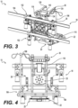
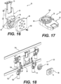
- the securing apparatus 10 holding a mobile equipment 12, which is a monitoring device 14 having a screen 16.
- the securing apparatus 10 comprises a frame 18 for supporting the mobile equipment, the frame 18 having one or more support members, and the coupling device 20 associated with the frame 18 and releasably attachable to the mobile equipment 12.
- One or more of the support members are attachable to the support surface.
- the coupling device 20 will be described in further detail below.
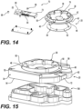
- the coupling device 20 comprises a base member 34 connectable to the support surface, and a release member connectable to the mobile equipment 12, the base member 34 and the release member 36 being releasably connectable together in a coupled position.
- the release member 36 has a body 38 which is a plate-like and has a first side 40 and a second side 42.
- the first side 40 of the release member body 38 defines a planar contact face 44 for contacting the base member 34.
- the second side 42 of the release member 36 has a collar 46 extending therefrom, the collar 46 positioned inwardly of a perimeter 48 of the release member 36 to define a flange portion 50 of the release member 36.
- the base member 34 comprises a plurality of spring loaded ball bearings 88 partially extending from recesses 90 formed in the planar contact portion 56 of the front side 52 of the base member 34 and engageable with corresponding recesses 92 defined in the planar contact face 44 of the release member 36.
- the spring loaded ball bearings 88 and the recesses 92 can guide the movement of the release member 36 relative to the base member 34.
- the coupling device 20 further comprises a top plate 98 attachable to the collar 46 of the release member 36 and attachable to the mobile equipment 12. As best seen in FIG. 7 , the top plate 98 is attached to the collar 46 by fasteners 100, such as screws. The top plate has an opening formed therein.
- the release member 36 when the base member 34 and the release member 36 are coupled together and in the lock position, the release member 36 is rotatable within the pocket 62 whilst maintaining the coupling.
- the perimeter 48 of the plate-like body 38 of the release member 36 is circular in shape
- the stop member 66 of the base member 34 is positioned substantially centrally of the planar contact portion 56
- the opening 76 of the release member 36 is positioned substantially centrally of the plate-like body 38, such that the release member 36 can be rotated within the pocket 62 when the stop member 66 is in the lock position.
- the stop member 66 can be considered to function also as a pivot point in these embodiments.
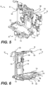
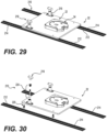
- the backing support member 26 comprises a pair of struts 118 extending upwardly from the base support member 22.
- An axis 120 of the struts 118 is transverse to an axis 122 of the base support member 22 ( FIG. 6 ).
- the coupling device 20 is positioned between the pair of struts 118 at a distance about midway along the struts 118.
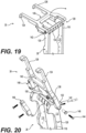
- a housing 148 is attached, such as by screws, to the top end 128 of the struts 118 at the back side and is sized and shaped to abut against an end of the struts 118 to delimit the movement of the top restraining member 30 downwardly.
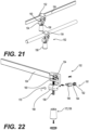
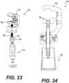
- the clamp 152 of FIG. 22 and 23 differs from the clamp 152 of FIG. 21 in that it has a clamping handle 172 which has the characteristics of torque wrench so as not to deform the clamp 152 or deform the piece on which the clamp 152 is attached to.
- the clamping handle 172 comprises a nut 174 which supports the handle 172.
- a connector 176 is filled and blocked by the nut 174.
- the connector 176 is round on the outside and has teeth that are square on one side and round on the other.
- the connector 176 is of the hexagonal type so as to be driven by the handle 172 which has the same internal shape.
- the connector 176 has a smooth hole in the center to freely rotate around the clamping screw 156.
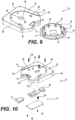
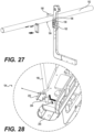
- the securing apparatus 10 comprises two hooks 180 attached to the frame 18 for releasably attaching the securing apparatus 10 to a horizontal support member 182, such as a pole or rail, on the support surface.
- each hook 180 has a free end 184 and a pivot end 186.
- Each hook 180 is pivotably attached to the struts 118 of the backing support member 26 by the pivot end 186.
- Each hook 180 is moveable between a deployed position in which the free end 184 extends away from the support member 182, and a retracted position in which the two hooks 180 lie substantially flat.
- the securing apparatus 10 comprises an IV pole mounting member 194, for mounting an IV pole 196 in a substantially vertical position, ready for use.
- an IV pole locking mechanism 198 ( FIG. 28 ) for securing the IV pole 196 in the IV pole mounting member 194.
- FIG. 28 is a close-up of the IV pole locking mechanism 198.
- the IV pole locking mechanism 198 comprises a housing 200 including a locking plate 202 having a rod lock slot 204, through which an end of the IV pole 196 is extended, and a spring 206 resiliently biasing the plate 202 away from the securing apparatus 10. Exerting a force on the locking plate 202 engages an edge of the rod lock slot 204 into a notch in the end of the IV pole 196 to retain the IV pole 196 in position.
Landscapes
- Engineering & Computer Science (AREA)
- General Engineering & Computer Science (AREA)
- Mechanical Engineering (AREA)
- Health & Medical Sciences (AREA)
- Biomedical Technology (AREA)
- Veterinary Medicine (AREA)
- Hematology (AREA)
- Life Sciences & Earth Sciences (AREA)
- Animal Behavior & Ethology (AREA)
- General Health & Medical Sciences (AREA)
- Public Health (AREA)
- Heart & Thoracic Surgery (AREA)
- Anesthesiology (AREA)
- Vascular Medicine (AREA)
- Fittings On The Vehicle Exterior For Carrying Loads, And Devices For Holding Or Mounting Articles (AREA)
- Casings For Electric Apparatus (AREA)
- Clamps And Clips (AREA)
- Pivots And Pivotal Connections (AREA)
- Mounting Of Printed Circuit Boards And The Like (AREA)
Applications Claiming Priority (3)
| Application Number | Priority Date | Filing Date | Title |
|---|---|---|---|
| US201962909408P | 2019-10-02 | 2019-10-02 | |
| PCT/CA2020/051329 WO2021062558A1 (en) | 2019-10-02 | 2020-10-02 | Coupling systems |
| EP20871589.6A EP4042424A4 (de) | 2019-10-02 | 2020-10-02 | Kopplungssysteme |
Related Parent Applications (1)
| Application Number | Title | Priority Date | Filing Date |
|---|---|---|---|
| EP20871589.6A Division EP4042424A4 (de) | 2019-10-02 | 2020-10-02 | Kopplungssysteme |
Publications (2)
| Publication Number | Publication Date |
|---|---|
| EP4534860A2 true EP4534860A2 (de) | 2025-04-09 |
| EP4534860A3 EP4534860A3 (de) | 2025-07-09 |
Family
ID=75336680
Family Applications (2)
| Application Number | Title | Priority Date | Filing Date |
|---|---|---|---|
| EP25160098.7A Pending EP4534860A3 (de) | 2019-10-02 | 2020-10-02 | Kupplungssysteme |
| EP20871589.6A Pending EP4042424A4 (de) | 2019-10-02 | 2020-10-02 | Kopplungssysteme |
Family Applications After (1)
| Application Number | Title | Priority Date | Filing Date |
|---|---|---|---|
| EP20871589.6A Pending EP4042424A4 (de) | 2019-10-02 | 2020-10-02 | Kopplungssysteme |
Country Status (4)
| Country | Link |
|---|---|
| US (2) | US11353155B2 (de) |
| EP (2) | EP4534860A3 (de) |
| CA (1) | CA3153484C (de) |
| WO (1) | WO2021062558A1 (de) |
Families Citing this family (11)
| Publication number | Priority date | Publication date | Assignee | Title |
|---|---|---|---|---|
| EP4534860A3 (de) * | 2019-10-02 | 2025-07-09 | Technologies CGC Inc. | Kupplungssysteme |
| CA3177448A1 (en) * | 2020-05-25 | 2021-12-02 | Technologies Cgc Inc. | Support systems for supporting equipment |
| DE102020119909A1 (de) * | 2020-07-28 | 2022-02-03 | Markus Schaub | Gerätehaltevorrichtung, insbesondere zur Befestigung eines mobilen medizinischen Gerätes, und medizinische Vorrichtung hiermit |
| CA3130720A1 (en) * | 2020-09-14 | 2022-03-14 | Technologies Cgc Inc. | Lockable coupling device |
| US11890118B2 (en) | 2021-03-24 | 2024-02-06 | Stryker Corporation | Patient support apparatus with support assembly for medical device |
| USD1018268S1 (en) * | 2021-08-16 | 2024-03-19 | The Braun Corporation | Wheelchair coupling mechanism |
| DE102022108457B4 (de) * | 2022-04-07 | 2024-03-28 | Starmed GmbH | Gerätehalter zur Aufnahme eines medizinischen Geräts |
| US12440410B2 (en) * | 2022-05-13 | 2025-10-14 | Technologies Cgc Inc. | Support assembly attachable to a patient support and patient support having same |
| USD1024048S1 (en) * | 2022-06-28 | 2024-04-23 | Annex Products Pty Ltd | Mounting head |
| USD1024049S1 (en) * | 2022-06-28 | 2024-04-23 | Annex Products Pty Ltd | Mounting head |
| DE102023112354A1 (de) * | 2023-05-10 | 2024-11-14 | Markus Schaub | Vorrichtung zur Aufnahme und Befestigung medizinischer Geräte |
Family Cites Families (27)
| Publication number | Priority date | Publication date | Assignee | Title |
|---|---|---|---|---|
| US4511158A (en) | 1982-08-27 | 1985-04-16 | Mt. Sinai Medical Center Of Greater Miami | Intravenous infusion pole attachment |
| US5152486A (en) | 1991-04-12 | 1992-10-06 | Kabanek Joseph R | Operating room table mate |
| US5362021A (en) | 1992-05-11 | 1994-11-08 | Phillips Medical Group, Inc. | Multi-adjustable surgical tray apparatus |
| US6247674B1 (en) * | 1999-09-02 | 2001-06-19 | Datascope Investment Corp. | Folding bedrail mount for a patient monitor |
| AU4596401A (en) | 2000-03-23 | 2001-10-03 | Ferno Washington | Iv pole |
| US7458743B2 (en) | 2000-09-25 | 2008-12-02 | The United States Of America As Represented By The Secretary Of The Army | Critical care platform for litters |
| GB0211231D0 (en) * | 2002-05-16 | 2002-06-26 | Fisco Tools Ltd | Quick-release arrangement |
| US20050258204A1 (en) * | 2004-05-21 | 2005-11-24 | Evans Michael S | Container with clip for storing and carrying trimmer line strips |
| US7273203B2 (en) * | 2005-02-23 | 2007-09-25 | Carnevali Jeffrey D | Locking device support |
| US8104729B2 (en) | 2007-03-09 | 2012-01-31 | Hill-Rom Services, Inc. | Transferable patient care equipment support |
| DE102008039651A1 (de) * | 2008-08-15 | 2010-02-18 | Weinmann Geräte für Medizin GmbH + Co. KG | Vorrichtung zur Halterung |
| US9367984B2 (en) | 2011-04-14 | 2016-06-14 | GCX Corporation | Enhanced modular drawer structures, systems, and methods |
| EP2842512B1 (de) | 2012-04-23 | 2022-08-10 | Terumo Kabushiki Kaisha | Gestell für medizinische vorrichtung |
| DE202012101686U1 (de) * | 2012-05-08 | 2012-09-21 | Easytrans As | Medizinisches Ausrüstungsbrett |
| CN102734379B (zh) * | 2012-06-09 | 2013-12-11 | 哈尔滨工业大学 | 基于电磁与静压气浮复合支撑的主动隔振装置 |
| JP5934447B2 (ja) | 2012-11-09 | 2016-06-15 | フレゼニウス ヴィアル エスアーエスFresenius Vial SAS | 医療装置をロックするロックシステム |
| US9944217B2 (en) * | 2013-02-11 | 2018-04-17 | Ferno-Washington, Inc. | Equipment mounting system |
| US10307313B2 (en) | 2013-02-11 | 2019-06-04 | Ferno-Washington, Inc. | Equipment mounting system |
| DK3354246T3 (en) * | 2013-02-11 | 2020-02-03 | Ferno Washington | Udstyrsmonteringssystem |
| US20150090849A1 (en) | 2013-09-30 | 2015-04-02 | Covidien Lp | Medical device supporting apparatus |
| CN203585745U (zh) * | 2013-11-22 | 2014-05-07 | 深圳迈瑞生物医疗电子股份有限公司 | 医疗设备支撑装置 |
| US20160324701A1 (en) | 2014-01-13 | 2016-11-10 | Ferno-Washington, Inc. | Accessory clamp for emergency cots |
| CN107466349B (zh) * | 2015-04-20 | 2020-02-14 | 创新办公产品公司 | 具有改进的翻转器和摩擦接头的铰接支撑臂 |
| DE102017110001B4 (de) * | 2017-05-09 | 2022-02-10 | Steffen Siemens | Befestigungsvorrichtung zur Befestigung eines medizinischen Geräts |
| US10869976B2 (en) * | 2017-06-30 | 2020-12-22 | Koninklijke Philips N.V. | Ventilator mount system |
| EP4534860A3 (de) * | 2019-10-02 | 2025-07-09 | Technologies CGC Inc. | Kupplungssysteme |
| US11007951B1 (en) * | 2020-02-28 | 2021-05-18 | National Creative Enterprises, Inc. | Mounting assembly |
-
2020
- 2020-10-02 EP EP25160098.7A patent/EP4534860A3/de active Pending
- 2020-10-02 WO PCT/CA2020/051329 patent/WO2021062558A1/en not_active Ceased
- 2020-10-02 CA CA3153484A patent/CA3153484C/en active Active
- 2020-10-02 EP EP20871589.6A patent/EP4042424A4/de active Pending
-
2021
- 2021-10-18 US US17/503,672 patent/US11353155B2/en active Active
-
2022
- 2022-05-06 US US17/738,658 patent/US11725770B2/en active Active
Also Published As
| Publication number | Publication date |
|---|---|
| US11353155B2 (en) | 2022-06-07 |
| US20220034444A1 (en) | 2022-02-03 |
| CA3153484A1 (en) | 2021-04-08 |
| CA3153484C (en) | 2025-07-22 |
| US20220268396A1 (en) | 2022-08-25 |
| WO2021062558A1 (en) | 2021-04-08 |
| EP4042424A4 (de) | 2023-10-25 |
| EP4042424A1 (de) | 2022-08-17 |
| US11725770B2 (en) | 2023-08-15 |
| EP4534860A3 (de) | 2025-07-09 |
Similar Documents
| Publication | Publication Date | Title |
|---|---|---|
| US11353155B2 (en) | Coupling systems | |
| JP6564467B2 (ja) | 容器取付アセンブリ | |
| US20250312205A1 (en) | Mounting apparatus for securing equipment to a patient transport system | |
| US6493890B2 (en) | Critical care platform for litters | |
| US20030115671A1 (en) | Critical care platform for litters | |
| US12310901B2 (en) | Coupling systems for releasably coupling equipment to a patient transport systems | |
| US20240084962A1 (en) | Remote Release Assembly for a Surface Mount | |
| KR20170032426A (ko) | 장치 장착 시스템 | |
| WO2006110440A1 (en) | Stanchion and cross rail assembly | |
| CN113438937A (zh) | 快速释放锚和配件 | |
| US20030046764A1 (en) | Critical care platform for litters | |
| US20250251075A1 (en) | Mounting assembly | |
| CN113693837B (zh) | 转运设备及具有其的车辆 | |
| US9631651B2 (en) | Quick release clamp for stretcher carriers and the like | |
| KR102894129B1 (ko) | 신속-해제 앵커 및 피팅부 |
Legal Events
| Date | Code | Title | Description |
|---|---|---|---|
| PUAI | Public reference made under article 153(3) epc to a published international application that has entered the european phase |
Free format text: ORIGINAL CODE: 0009012 |
|
| STAA | Information on the status of an ep patent application or granted ep patent |
Free format text: STATUS: REQUEST FOR EXAMINATION WAS MADE |
|
| 17P | Request for examination filed |
Effective date: 20250225 |
|
| AC | Divisional application: reference to earlier application |
Ref document number: 4042424 Country of ref document: EP Kind code of ref document: P |
|
| AK | Designated contracting states |
Kind code of ref document: A2 Designated state(s): AL AT BE BG CH CY CZ DE DK EE ES FI FR GB GR HR HU IE IS IT LI LT LU LV MC MK MT NL NO PL PT RO RS SE SI SK SM TR |
|
| REG | Reference to a national code |
Ref country code: DE Ref legal event code: R079 Free format text: PREVIOUS MAIN CLASS: F16B0005060000 Ipc: A61M0005140000 |
|
| PUAL | Search report despatched |
Free format text: ORIGINAL CODE: 0009013 |
|
| AK | Designated contracting states |
Kind code of ref document: A3 Designated state(s): AL AT BE BG CH CY CZ DE DK EE ES FI FR GB GR HR HU IE IS IT LI LT LU LV MC MK MT NL NO PL PT RO RS SE SI SK SM TR |
|
| RIC1 | Information provided on ipc code assigned before grant |
Ipc: F16B 2/12 20060101ALN20250605BHEP Ipc: F16B 2/10 20060101ALN20250605BHEP Ipc: F16B 5/06 20060101ALI20250605BHEP Ipc: A61M 5/14 20060101AFI20250605BHEP |