EP4534786A1 - Vehicle door assembly and vehicle - Google Patents
Vehicle door assembly and vehicle Download PDFInfo
- Publication number
- EP4534786A1 EP4534786A1 EP23814770.6A EP23814770A EP4534786A1 EP 4534786 A1 EP4534786 A1 EP 4534786A1 EP 23814770 A EP23814770 A EP 23814770A EP 4534786 A1 EP4534786 A1 EP 4534786A1
- Authority
- EP
- European Patent Office
- Prior art keywords
- handle
- assembly
- vehicle door
- unlocking
- pivot shaft
- Prior art date
- Legal status (The legal status is an assumption and is not a legal conclusion. Google has not performed a legal analysis and makes no representation as to the accuracy of the status listed.)
- Pending
Links
Images


Classifications
-
- E—FIXED CONSTRUCTIONS
- E05—LOCKS; KEYS; WINDOW OR DOOR FITTINGS; SAFES
- E05B—LOCKS; ACCESSORIES THEREFOR; HANDCUFFS
- E05B85/00—Details of vehicle locks not provided for in groups E05B77/00 - E05B83/00
- E05B85/10—Handles
- E05B85/14—Handles pivoted about an axis parallel to the wing
- E05B85/18—Handles pivoted about an axis parallel to the wing a longitudinal grip part being pivoted about an axis parallel to the longitudinal axis of the grip part
-
- E—FIXED CONSTRUCTIONS
- E05—LOCKS; KEYS; WINDOW OR DOOR FITTINGS; SAFES
- E05B—LOCKS; ACCESSORIES THEREFOR; HANDCUFFS
- E05B13/00—Devices preventing the key or the handle or both from being used
- E05B13/002—Devices preventing the key or the handle or both from being used locking the handle
-
- E—FIXED CONSTRUCTIONS
- E05—LOCKS; KEYS; WINDOW OR DOOR FITTINGS; SAFES
- E05B—LOCKS; ACCESSORIES THEREFOR; HANDCUFFS
- E05B81/00—Power-actuated vehicle locks
- E05B81/24—Power-actuated vehicle locks characterised by constructional features of the actuator or the power transmission
- E05B81/26—Output elements
- E05B81/28—Linearly reciprocating elements
-
- E—FIXED CONSTRUCTIONS
- E05—LOCKS; KEYS; WINDOW OR DOOR FITTINGS; SAFES
- E05B—LOCKS; ACCESSORIES THEREFOR; HANDCUFFS
- E05B85/00—Details of vehicle locks not provided for in groups E05B77/00 - E05B83/00
- E05B85/10—Handles
- E05B85/103—Handles creating a completely closed wing surface
-
- E—FIXED CONSTRUCTIONS
- E05—LOCKS; KEYS; WINDOW OR DOOR FITTINGS; SAFES
- E05B—LOCKS; ACCESSORIES THEREFOR; HANDCUFFS
- E05B15/00—Other details of locks; Parts for engagement by bolts of fastening devices
- E05B15/004—Lost motion connections
Definitions
- the present disclosure relates to the field of vehicle technology, and in particular to a vehicle door assembly and a vehicle.
- the hidden door handle extends outward to unlock the door when it is necessary to open the door.
- the extension of the door handle is easily hindered, thus affecting the normal unlocking of the door.
- the present disclosure aims to solve at least one of the technical problems existing in the prior art.
- the present disclosure provides a vehicle door assembly, which can achieve complete hiding of the handle by rotating the handle toward the inner side of the vehicle door.
- the present disclosure further provides a vehicle including the vehicle door assembly.
- An embodiment according to a first aspect of the present disclosure provides a vehicle door assembly, including: a vehicle door, the vehicle door is provided with a handle groove; an unlocking assembly, the unlocking assembly is arranged in the vehicle door for unlocking the vehicle door; and a handle assembly, the handle assembly is arranged in the handle groove, the handle assembly includes a handle and a first pivot shaft, the first pivot shaft is pivotally arranged in the handle groove, the handle is arranged on the first pivot shaft, and the handle has a retracted position and an unlocking position; wherein, when the handle is in the retracted position, the handle is located at the opening of the handle groove and does not protrude beyond the surface of the vehicle door; when the handle is in the unlocking position, the handle is located in the handle groove, and the handle is in contact with the unlocking assembly, so as to drive the unlocking assembly to unlock the vehicle door under the action of an external force.
- the handle is rotated inwardly to ensure that the handle is always in a hidden state, which not only can reduce the wind resistance, but also can avoid the trouble that the outward-extending hidden handle cannot be opened in a freezing environment.
- the power assembly includes a driving member and a transmission device, the transmission device is transmission-connected between the first pivot shaft and the driving member.
- the transmission device includes: a transmission member, a rocker arm and a slider, the transmission member is transmission-connected to the first pivot shaft, the slider is transmission-connected to the driving member, a sliding slot is provided in the slider, the rocker arm is connected to the transmission member, and one end of the rocker arm is inserted into the sliding slot, wherein, when the driving member pushes the slider to reciprocate, the inside wall of the sliding slot drives the rocker arm to swing back and forth, and the rocker arm drives the first pivot shaft to rotate by the transmission member.
- the at least two transmission members include a driving gear and a driven gear
- the diameter of the driving gear is larger than the diameter of the driven gear
- the driving gear and the driven gear are meshed for transmission
- the driving gear is arranged on the rocker arm
- the driven gear is arranged on the first pivot shaft.
- the slider further includes: a mounting groove, the driving member is provided with a limiting plate, and the limiting plate is embedded in the mounting groove.
- the vehicle door assembly also includes a shell and a fixing plate, the handle groove is formed between the shell and the vehicle door, the fixing plate is connected to the shell, the first pivot shaft and the second pivot shaft are both connected to the fixing plate.
- the vehicle door assembly further includes: a locking assembly; the locking assembly includes a locking block and a puller, the locking block is connected to the puller, wherein, when the handle is in the retracted position, the locking block extends to the back of the handle to block the rotation of the handle.
- An embodiment according to a second aspect of the present disclosure provides a vehicle, including: a vehicle door assembly according to the above embodiment of the first aspect of the present disclosure.
- first and second are used merely for the purpose of description, and shall not be construed as indicating or implying relative importance or implying a quantity of indicated technical features. Therefore, a feature restricted by “first” or “second” may explicitly indicate or implicitly include at least one of such features.
- “multiple” means at least two, for example, two or three.
- a vehicle door assembly 100 that is provided in the embodiment of the present disclosure is described below with reference to FIGS. 1 to 8 .
- the vehicle door assembly 100 includes a vehicle door 1, an unlocking assembly 2, and a handle assembly 3.
- the unlocking assembly 2 is arranged in the vehicle door 1 to unlock the vehicle door 1.
- a handle groove 11 is provided in the vehicle door 1, and the handle assembly 3 is arranged in the handle groove 11.
- the handle assembly 3 includes a handle 31 and a first pivot shaft 32.
- the first pivot shaft 32 is pivotally arranged in the handle groove 11.
- the handle 31 is arranged on the first pivot shaft 32.
- the handle 31 has a retracted position and an unlocking position. When the handle 31 is in the retracted position, the handle 31 is located at the opening of the handle groove 11 and does not protrude beyond the surface of the vehicle door 1.
- the handle 31 is located in the handle groove 11, and the handle 31 is in contact with the unlocking assembly 2, so as to drive the unlocking assembly 2 to unlock the vehicle door 1 under the action of an external force.
- the handle 31 will rotate toward the inner side of the vehicle door 1 when in use.
- the handle 31 will not protrude beyond the surface of the vehicle door 1 even when it is in the unlocking position, so that the handle 31 can be completely hidden.
- Such a structural design on the one hand, is conducive to reducing wind resistance and fuel consumption; on the other hand, the handle 31 is integrated with the shape of the vehicle door 1, thereby increasing the texture of the vehicle door assembly 100.
- the power assembly 4 includes a driving member 5 and a transmission device 6, and the transmission device 6 is transmission-connected between the first pivot shaft 32 and the driving member 5.
- the driving member 5 drives the first pivot shaft 32 to rotate by the transmission device 6, and the first pivot shaft 32 rotates together with the handle 31, so that the handle 31 reciprocates between the retracted position and the unlocking position. Since the rotation angle of the handle 31 is relatively large, if the driving member 5 is directly connected to the first pivot shaft 32, it is easy to cause the stroke of the driving member 5 to be too long, and the stroke space required is relatively large, which is not conducive to the arrangement of the power assembly 4. Therefore, by providing the transmission member 61, it is possible to avoid the driving member 5 being directly connected to the first pivot shaft 32 for transmission, thereby reducing the stroke space occupied by the driving member 5, and facilitating the arrangement of the power assembly 4.
- the driving member 5 when the handle needs to be used to unlock the vehicle door 1, the driving member 5 will transmit power by the transmission device 6, thereby driving the handle 31 to rotate toward the inner side of the vehicle to the unlocking position, and then the user presses the handle 31 and drives the unlocking assembly 2 to rotate, thereby opening the vehicle door 1 by the unlocking assembly 2.
- the transmission device 6 needs to set a clearance space.
- the telescopic rod of the driving member 5 When in use, the telescopic rod of the driving member 5 will extend, driving the slider 63 to move. At this time, the inside wall of the sliding slot 631 close to the driving member 5 will push the rocker arm 62 to rotate forward, and the rocker arm 62 transmits power to the first pivot shaft 32 by the transmission member 61, thereby driving the handle 31 to rotate to the unlocking position. Subsequently, when the user needs to unlock the vehicle door 1, press the handle 31 hard, thereby driving the unlocking assembly 2 to rotate. At this time, the first pivot shaft 32 will transmit the effect of this force to the transmission member 61, thereby causing the rocker arm 62 to continue to rotate forward, that is, the rocker arm 62 rotates alone to the side away from the driving member 5.
- the segmented motion characteristics of the handle 31 can be effectively realized, which not only has a simple structure and low functional cost, but is also stable and not easy to be damaged, thereby improving the reliability of the transmission device 6.
- the second pivot shaft 22 is arranged on one side of the first pivot shaft 32.
- the unlocking swing arm 21 is arranged under the unlocking position and is in close contact with the handle 31, so that it is convenient for the user to press the handle 31 to drive the unlocking swing arm 21 to rotate.
- the unlocking fastener 23 also rotates under the drive of the second pivot shaft 22, so that the lock core of the vehicle door 1 can be disengaged from the door bolt, thereby unlocking the vehicle door 1.
- the shell 7 is arranged in the vehicle door 1, and the periphery of the shell 7 is connected to the inside wall of the vehicle door 1.
- the setting of the shell 7 can protect the rotation of the handle 31 and the unlocking swing arm 21 in the handle groove 11, thereby preventing other components in the vehicle door 1 from interfering with the rotation of the handle 31 and the unlocking swing arm 21 which affects the normal unlocking function of the vehicle door 1.
- the shell 7 can also serve as a fixing seat, that is, the fixing plate 71 is arranged on the shell 7, so as to facilitate the first pivot shaft 32 and the second pivot shaft 22 to be assembled on the fixing plate 71, thereby simplifying the assembly structure and improving the integration of the vehicle door assembly 100.
- the vehicle door assembly 100 further includes a locking assembly 8, the locking assembly 8 includes a locking block 81 and a puller 82, and the locking block 81 is connected to the puller 82.
- the locking block 81 extends to the back of the handle 31 to lock the rotation of the handle 31.
- the rotation of the handle 31 is locked by the locking block 81, thereby playing an anti-theft role and preventing external force from violently pushing the handle 31 to rotate inward to open the vehicle door 1.
- the vehicle according to the embodiment of the present disclosure includes the vehicle door assembly 100 of the above embodiment.
- a vehicle using the above-mentioned vehicle door assembly 100 can improve the overall texture and operating comfort, which is conducive to improving the market competitiveness of the vehicle.
Landscapes
- Lock And Its Accessories (AREA)
Abstract
Description
- The present disclosure relates to the field of vehicle technology, and in particular to a vehicle door assembly and a vehicle.
- At present, the door handles of most cars are exposed, but as competition in the automobile market continues to intensify, the door handles are gradually developing into hidden door handles.
- In the related art, the hidden door handle extends outward to unlock the door when it is necessary to open the door. However, when the vehicle is in a freezing environment, the extension of the door handle is easily hindered, thus affecting the normal unlocking of the door. There are also hidden handles that leave the door handles exposed all the time while the car is driving. This not only increases air resistance, but also easy to make consumers mistakenly believe that the handles are faulty.
- The present disclosure aims to solve at least one of the technical problems existing in the prior art. To this end, the present disclosure provides a vehicle door assembly, which can achieve complete hiding of the handle by rotating the handle toward the inner side of the vehicle door.
- The present disclosure further provides a vehicle including the vehicle door assembly.
- An embodiment according to a first aspect of the present disclosure provides a vehicle door assembly, including: a vehicle door, the vehicle door is provided with a handle groove; an unlocking assembly, the unlocking assembly is arranged in the vehicle door for unlocking the vehicle door; and a handle assembly, the handle assembly is arranged in the handle groove, the handle assembly includes a handle and a first pivot shaft, the first pivot shaft is pivotally arranged in the handle groove, the handle is arranged on the first pivot shaft, and the handle has a retracted position and an unlocking position; wherein, when the handle is in the retracted position, the handle is located at the opening of the handle groove and does not protrude beyond the surface of the vehicle door; when the handle is in the unlocking position, the handle is located in the handle groove, and the handle is in contact with the unlocking assembly, so as to drive the unlocking assembly to unlock the vehicle door under the action of an external force.
- According to the vehicle door assembly in an embodiment of the present disclosure, the handle is rotated inwardly to ensure that the handle is always in a hidden state, which not only can reduce the wind resistance, but also can avoid the trouble that the outward-extending hidden handle cannot be opened in a freezing environment.
- According to some embodiments of the present disclosure, the vehicle door assembly further includes: a power assembly, which is transmission-connected to the first pivot shaft to drive the handle to rotate between the retracted position and the unlocking position.
- According to some embodiments of the present disclosure, the power assembly includes a driving member and a transmission device, the transmission device is transmission-connected between the first pivot shaft and the driving member.
- According to some embodiments of the present disclosure, the transmission device includes: a transmission member, a rocker arm and a slider, the transmission member is transmission-connected to the first pivot shaft, the slider is transmission-connected to the driving member, a sliding slot is provided in the slider, the rocker arm is connected to the transmission member, and one end of the rocker arm is inserted into the sliding slot, wherein, when the driving member pushes the slider to reciprocate, the inside wall of the sliding slot drives the rocker arm to swing back and forth, and the rocker arm drives the first pivot shaft to rotate by the transmission member.
- According to some embodiments of the present disclosure, there are at least two transmission members, and the at least two transmission members include a driving gear and a driven gear, the diameter of the driving gear is larger than the diameter of the driven gear, the driving gear and the driven gear are meshed for transmission, the driving gear is arranged on the rocker arm, and the driven gear is arranged on the first pivot shaft.
- According to some embodiments of the present disclosure, the slider further includes: a mounting groove, the driving member is provided with a limiting plate, and the limiting plate is embedded in the mounting groove.
- According to some embodiments of the present disclosure, the unlocking assembly includes an unlocking swing arm, a second pivot shaft and an unlocking fastener, the second pivot shaft is respectively transmission-connected to the unlocking swing arm and the unlocking fastener, and the unlocking swing arm rotates around the second pivot shaft under the action of the handle and drives the unlocking fastener to rotate to unlock the vehicle door.
- According to some embodiments of the present disclosure, the vehicle door assembly also includes a shell and a fixing plate, the handle groove is formed between the shell and the vehicle door, the fixing plate is connected to the shell, the first pivot shaft and the second pivot shaft are both connected to the fixing plate.
- According to some embodiments of the present disclosure, the vehicle door assembly further includes: a locking assembly; the locking assembly includes a locking block and a puller, the locking block is connected to the puller, wherein, when the handle is in the retracted position, the locking block extends to the back of the handle to block the rotation of the handle.
- An embodiment according to a second aspect of the present disclosure provides a vehicle, including: a vehicle door assembly according to the above embodiment of the first aspect of the present disclosure.
- The additional aspects and advantages of the present disclosure are partially provided in the following descriptions, some of which will become apparent from the following descriptions or may be learned from practices of the present disclosure.
- The above and/or additional aspects and advantages of the present disclosure will become apparent and easily understood from the description of the embodiments in conjunction with the following drawings, in which:
-
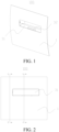
FIG. 1 is a schematic drawing of a vehicle door assembly according to an embodiment of the present disclosure; -
FIG. 2 is a front view of a vehicle door assembly according to an embodiment of the present disclosure; -
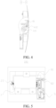
FIG. 3 is a cross-sectional view along line A-A inFIG. 2 ; -
FIG. 4 is a cross-sectional view along line B-B inFIG. 2 ; -
FIG. 5 is a rear view of a vehicle door assembly according to an embodiment of the present disclosure; -
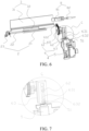
FIG. 6 is a schematic drawing of the handle assembly and the unlocking assembly according to an embodiment of the present disclosure; -
FIG. 7 is an enlarged view of the circled portion C inFIG. 6 ; and -
FIG. 8 is an assembly drawing of the locking assembly and the handle according to an embodiment of the present disclosure. -
- 100. Vehicle door assembly;
- 1. Vehicle door; 11. Handle groove; 2. Unlocking assembly; 21. Unlocking swing arm; 22. Second pivot shaft; 23. Unlocking fastener; 3. Handle assembly; 31. Handle; 32. First pivot shaft; 4. Power assembly; 5. Driving member; 51. Limiting plate; 6. Transmission device; 61. Transmission member; 611. Driving gear; 612. Driven gear; 62. Rocker arm; 63. Slider; 631. Sliding slot; 632. Mounting groove; 7. Shell; 71. Fixing plate; 8. Locking assembly; 81. Locking block; 82. Puller.
- The embodiments of the present disclosure are described below in detail. Examples of the embodiments are shown in the accompanying drawings, wherein the same or similar reference numerals in all the accompanying drawings indicate same or similar components or components having same or similar functions. The embodiments described below with reference to the accompanying drawings are exemplary, are intended to explain the present disclosure and cannot be construed as a limitation on the present disclosure.
- In the description of the present disclosure, it should be understood that the terms "center", "up", "down", "front", "back", "left", "right", "vertical", "horizontal", "top", "bottom", "inside", "outside", etc., indicating orientations or positional relationships, are based on the orientations or positional relationships shown in the accompanying drawings, and are used merely for the purpose of description and simplifying the description, and shall not be construed as indicating or implying that the referred device or component must have a specific orientation or be constructed and operated in a specific orientation, and therefore cannot be construed as a limitation on the present disclosure.
- It should be noted that the terms "first" and "second" are used merely for the purpose of description, and shall not be construed as indicating or implying relative importance or implying a quantity of indicated technical features. Therefore, a feature restricted by "first" or "second" may explicitly indicate or implicitly include at least one of such features. In the descriptions of the present disclosure, unless explicitly specified, "multiple" means at least two, for example, two or three.
- A
vehicle door assembly 100 that is provided in the embodiment of the present disclosure is described below with reference toFIGS. 1 to 8 . - Combined with
FIG. 1-FIG.3 , thevehicle door assembly 100 according to an embodiment of the present disclosure includes avehicle door 1, an unlockingassembly 2, and ahandle assembly 3. The unlockingassembly 2 is arranged in thevehicle door 1 to unlock thevehicle door 1. Ahandle groove 11 is provided in thevehicle door 1, and thehandle assembly 3 is arranged in thehandle groove 11. Thehandle assembly 3 includes ahandle 31 and afirst pivot shaft 32. Thefirst pivot shaft 32 is pivotally arranged in thehandle groove 11. Thehandle 31 is arranged on thefirst pivot shaft 32. Thehandle 31 has a retracted position and an unlocking position. When thehandle 31 is in the retracted position, thehandle 31 is located at the opening of thehandle groove 11 and does not protrude beyond the surface of thevehicle door 1. When thehandle 31 is in the unlocking position, thehandle 31 is located in thehandle groove 11, and thehandle 31 is in contact with the unlockingassembly 2, so as to drive the unlockingassembly 2 to unlock thevehicle door 1 under the action of an external force. - Specifically, when the
handle 31 is not in use, thehandle 31 is in a retracted position, that is, thehandle 31 is in a hidden state, at this time, thehandle 31 is flush with the outer sheet metal surface of thevehicle door 1. When thehandle 31 needs to be used, thehandle 31 is rotated toward the inner side of the vehicle at a certain angle to expose the space of thehandle groove 11. By pressing thehandle 31, thehandle 31 will touch the unlockingassembly 2, thus opening thevehicle door 1 by the unlockingassembly 2. After unlocking is completed, thehandle 31 will return from the unlocking position to the retracted position, at which time thehandle 31 is flush with the outer sheet metal surface of thevehicle door 1 and returns to the hidden state. - In an embodiment of the present disclosure, the
handle 31 will rotate toward the inner side of thevehicle door 1 when in use. Thehandle 31 will not protrude beyond the surface of thevehicle door 1 even when it is in the unlocking position, so that thehandle 31 can be completely hidden. Such a structural design, on the one hand, is conducive to reducing wind resistance and fuel consumption; on the other hand, thehandle 31 is integrated with the shape of thevehicle door 1, thereby increasing the texture of thevehicle door assembly 100. - Therefore, by turning the
handle 31 inward, it can be ensured that thehandle 31 is always in a hidden state, which not only reduces wind resistance, but also avoids the trouble that the outward-extending hidden handle cannot be opened in a freezing environment. - Besides, as shown in
FIG. 5 andFIG. 6 , thevehicle door assembly 100 further includes apower assembly 4, which is in transmission connection with thefirst pivot shaft 32 to drive thehandle 31 to rotate between the retracted position and the unlocking position. Specifically, when thehandle 31 is in use, thepower assembly 4 automatically rotates thehandle 31 from the retracted position to the unlocking position, and then the user presses thehandle 31 to drive the unlockingassembly 2 to unlock thevehicle door 1. After unlocking, thepower assembly 4 restores thehandle 31 from the unlocking state to the retracted position. This arrangement can realize the automatic turning operation of thehandle 31, thereby improving user experience, and can also avoid the situation where the spring element pinches the hand and affects the user's operation. - Moreover, as shown in
FIG. 6 , thepower assembly 4 includes a drivingmember 5 and atransmission device 6, and thetransmission device 6 is transmission-connected between thefirst pivot shaft 32 and the drivingmember 5. The drivingmember 5 drives thefirst pivot shaft 32 to rotate by thetransmission device 6, and thefirst pivot shaft 32 rotates together with thehandle 31, so that thehandle 31 reciprocates between the retracted position and the unlocking position. Since the rotation angle of thehandle 31 is relatively large, if the drivingmember 5 is directly connected to thefirst pivot shaft 32, it is easy to cause the stroke of the drivingmember 5 to be too long, and the stroke space required is relatively large, which is not conducive to the arrangement of thepower assembly 4. Therefore, by providing thetransmission member 61, it is possible to avoid the drivingmember 5 being directly connected to thefirst pivot shaft 32 for transmission, thereby reducing the stroke space occupied by the drivingmember 5, and facilitating the arrangement of thepower assembly 4. - Furthermore, as shown in
FIG. 6 , thetransmission device 6 includes atransmission member 61, arocker arm 62 and aslider 63. Thetransmission member 61 is transmission-connected to thefirst pivot shaft 32, theslider 63 is transmission-connected to the drivingmember 5, a slidingslot 631 is provided in theslider 63, therocker arm 62 is connected to thetransmission member 61, and one end of therocker arm 62 is inserted into the slidingslot 631. When the drivingmember 5 pushes theslider 63 to move back and forth, the inside wall of the slidingslot 631 drives therocker arm 62 to swing back and forth, and therocker arm 62 drives thefirst pivot shaft 32 to rotate by thetransmission member 61. - Specifically, according to the contents of the above embodiments, when the handle needs to be used to unlock the
vehicle door 1, the drivingmember 5 will transmit power by thetransmission device 6, thereby driving thehandle 31 to rotate toward the inner side of the vehicle to the unlocking position, and then the user presses thehandle 31 and drives the unlockingassembly 2 to rotate, thereby opening thevehicle door 1 by the unlockingassembly 2. During this process, after the drivingmember 5 rotates thehandle 31 to the unlocking position, the drivingmember 5 will stop, but thehandle 31 needs to continue to move downward under the pressure of the user to press the unlockingassembly 2 to rotate. Therefore, in order to realize the secondary rotation of thehandle 31, thetransmission device 6 needs to set a clearance space. By providing a slidingslot 631 in theslider 63, and the length of the slidingslot 631 is greater than the rotation circumference of thehandle 31 during its second rotation, it is ensured that thehandle 31 smoothly drives the unlockingassembly 2 to rotate. - When in use, the telescopic rod of the driving
member 5 will extend, driving theslider 63 to move. At this time, the inside wall of the slidingslot 631 close to the drivingmember 5 will push therocker arm 62 to rotate forward, and therocker arm 62 transmits power to thefirst pivot shaft 32 by thetransmission member 61, thereby driving thehandle 31 to rotate to the unlocking position. Subsequently, when the user needs to unlock thevehicle door 1, press thehandle 31 hard, thereby driving the unlockingassembly 2 to rotate. At this time, thefirst pivot shaft 32 will transmit the effect of this force to thetransmission member 61, thereby causing therocker arm 62 to continue to rotate forward, that is, therocker arm 62 rotates alone to the side away from the drivingmember 5. - Through the cooperation between the
rocker arm 62 and theslider 63, the segmented motion characteristics of thehandle 31 can be effectively realized, which not only has a simple structure and low functional cost, but is also stable and not easy to be damaged, thereby improving the reliability of thetransmission device 6. - In an embodiment of the present disclosure, as shown in
Fig. 4 andFig.6 , there are at least twotransmission members 61, and the at least twotransmission members 61 include adriving gear 611 and a drivengear 612. The diameter of thedriving gear 611 is greater than the diameter of the drivengear 612. Thedriving gear 611 and the drivengear 612 are meshed for transmission. Thedriving gear 611 is arranged on therocker arm 62, and the drivengear 612 is arranged on thefirst pivot shaft 32. - Specifically, by setting up a gear transmission, the direction of power transmission of the driving
member 5 can be realized, so that the rotation direction of thehandle 31 is opposite to the moving direction of theslider 63 driven by the drivingmember 5, which facilitates thehandle 31 moving in the second stage to drive the unlockingswing arm 21 to unlock thevehicle door 1. At the same time, by setting thedriving gear 611 larger than the drivengear 612, the moving distance of theslider 63 can be enlarged, thereby reducing the transmission space occupied by thetransmission device 6, and more other components can be placed in the limited space of thevehicle door 1. - In an embodiment of the present disclosure, as shown in
FIG. 6 and FIG. 7 , theslider 63 further includes a mountinggroove 632, and the drivingmember 5 is provided with a limitingplate 51, and the limitingplate 51 is embedded in the mountinggroove 632. Specifically, since theslider 63 is a wearing part and is prone to wear and tear between therocker arm 62 after long-term use, a split connection is adopted between theslider 63 and the telescopic rod of the drivingmember 5, which can facilitate independent replacement of theslider 63 and reduce the cost of use. - In an embodiment of the present disclosure, as shown in
Fig. 6 , the unlockingassembly 2 also includes an unlockingswing arm 21, asecond pivot shaft 22 and an unlockingfastener 23, wherein thesecond pivot shaft 22 is respectively transmission-connected to the unlockingswing arm 21 and the unlockingfastener 23, and the unlockingswing arm 21 rotates around thesecond pivot shaft 22 under the action of thehandle 31 and drives the unlockingfastener 23 to rotate to unlock thevehicle door 1. - Specifically, when the
first pivot shaft 32 is arranged under thehandle groove 11, thesecond pivot shaft 22 is arranged on one side of thefirst pivot shaft 32. At this time, the unlockingswing arm 21 is arranged under the unlocking position and is in close contact with thehandle 31, so that it is convenient for the user to press thehandle 31 to drive the unlockingswing arm 21 to rotate. The unlockingfastener 23 also rotates under the drive of thesecond pivot shaft 22, so that the lock core of thevehicle door 1 can be disengaged from the door bolt, thereby unlocking thevehicle door 1. Through such a setting, it is easy to achieve the linkage between the unlockingswing arm 21 and thehandle 31, avoiding the user's direct manual contact with the unlockingswing arm 21, which is beneficial to the arrangement of thehandle assembly 3 and the unlockingassembly 2. - In addition, as shown in
FIG. 3 , thevehicle door assembly 100 further includes a shell 7 and a fixingplate 71, thehandle groove 11 is formed between the shell 7 and thevehicle door 1, the fixingplate 71 is connected to the shell 7, and thefirst pivot shaft 32 and thesecond pivot shaft 22 are both connected to the fixingplate 71. - Specifically, the shell 7 is arranged in the
vehicle door 1, and the periphery of the shell 7 is connected to the inside wall of thevehicle door 1. The setting of the shell 7 can protect the rotation of thehandle 31 and the unlockingswing arm 21 in thehandle groove 11, thereby preventing other components in thevehicle door 1 from interfering with the rotation of thehandle 31 and the unlockingswing arm 21 which affects the normal unlocking function of thevehicle door 1. At the same time, the shell 7 can also serve as a fixing seat, that is, the fixingplate 71 is arranged on the shell 7, so as to facilitate thefirst pivot shaft 32 and thesecond pivot shaft 22 to be assembled on the fixingplate 71, thereby simplifying the assembly structure and improving the integration of thevehicle door assembly 100. - In an embodiment of the present disclosure, as shown in
FIG. 5 andFIG. 8 , thevehicle door assembly 100 further includes a lockingassembly 8, the lockingassembly 8 includes a lockingblock 81 and apuller 82, and the lockingblock 81 is connected to the puller 82.When thehandle 31 is in the retracted position, the lockingblock 81 extends to the back of thehandle 31 to lock the rotation of thehandle 31. Specifically, when thevehicle door 1 is in a closed state, the rotation of thehandle 31 is locked by the lockingblock 81, thereby playing an anti-theft role and preventing external force from violently pushing thehandle 31 to rotate inward to open thevehicle door 1. - The vehicle according to the embodiment of the present disclosure includes the
vehicle door assembly 100 of the above embodiment. Specifically, a vehicle using the above-mentionedvehicle door assembly 100 can improve the overall texture and operating comfort, which is conducive to improving the market competitiveness of the vehicle. - In the description of this specification, the description of the reference terms "an embodiment", "some embodiments", "an example", "a specific example", "some examples", and the like means that specific features, structures, materials or characteristics described in combination with the embodiment(s) or example(s) are included in at least one embodiment or example of the present disclosure. In this specification, exemplary descriptions of the foregoing terms do not necessarily refer to the same embodiment or example. In addition, the described specific features, structures, materials, or characteristics may be combined in a proper manner in any one or more of the embodiments or examples.
- Although the embodiments of the present disclosure have been shown and described above, it can be understood that, the foregoing embodiments are exemplary and should not be understood as limitation to the present disclosure. A person of ordinary skill in the art can make changes, modifications, replacements, or variations to the foregoing embodiments within the scope of the present disclosure.
Claims (10)
- A vehicle door assembly (100), comprising:a vehicle door (1), the vehicle door (1) being provided with a handle groove (11);an unlocking assembly (2), the unlocking assembly (2) being arranged in the vehicle door (1) and configured to unlock the vehicle door (1); anda handle assembly (3), the handle assembly (3) being arranged in the handle groove (11), the handle assembly (3) including a handle (31) and a first pivot shaft (32), the first pivot shaft (32) being pivotally arranged in the handle groove (11), the handle (31) being arranged on the first pivot shaft (32), and the handle (31) having a retracted position and an unlocking position;wherein when the handle (31) is in the retracted position, the handle (31) is located at an opening of the handle groove (11) and does not protrude beyond a surface of the vehicle door (1); when the handle (31) is in the unlocking position, the handle (31) is located in the handle groove (11), and the handle (31) is in contact with the unlocking assembly (2) so as to drive the unlocking assembly (2) to unlock the vehicle door (1) under an action of an external force.
- The vehicle door assembly (100) according to claim 1, further comprising:
a power assembly (4), the power assembly (4) being in transmission connection with the first pivot shaft (32) to drive the handle (31) to rotate between the retracted position and the unlocking position. - The vehicle door assembly (100) according to claim 2, wherein the power assembly (4) comprises a driving member (5) and a transmission device (6), and the transmission device (6) is transmission-connected between the first pivot shaft (32) and the driving member (5).
- The vehicle door assembly (100) according to claim 3, wherein the transmission device (6) comprises a transmission member (61), a rocker arm (62), and a slider (63), the transmission member (61) is transmission-connected to the first pivot shaft (32), the slider (63) is transmission-connected to the driving member (5), a sliding slot (631) is provided in the slider (63), the rocker arm (62) is connected to the transmission member (61), and one end of the rocker arm (62) is inserted into the sliding slot (631), wherein, when the driving member (5) pushes the slider (63) to move back and forth, an inside wall of the sliding slot (631) drives the rocker arm (62) to swing back and forth, and the rocker arm (62) drives the first pivot shaft (32) to rotate by the transmission member (61).
- The vehicle door assembly (100) according to claim 4, comprising at least two transmission members (61) , and wherein the at least two transmission members (61) include a driving gear (611) and a driven gear (612), a diameter of the driving gear (611) is larger than the diameter of the driven gear (612), the driving gear (611) and the driven gear (612) are meshed for transmission, the driving gear (611) is arranged on the rocker arm (62), and the driven gear (612) is arranged on the first pivot shaft (32).
- The vehicle door assembly (100) according to claim 4 or 5, wherein the slider (63) is further provided with a mounting groove (632), the driving member (5) is provided with a limiting plate (51), and the limiting plate (51) is embedded in the mounting groove (632).
- The vehicle door assembly (100) according to any one of claims 1 to 6, wherein the unlocking assembly (2) comprises an unlocking swing arm (21), a second pivot shaft (22) and an unlocking fastener (23), the second pivot shaft (22) is respectively transmission-connected to the unlocking swing arm (21) and the unlocking fastener (23), and the unlocking swing arm (21) rotates around the second pivot shaft (22) under an action of the handle (31) and drives the unlocking fastener (23) to rotate, in order to unlock the vehicle door (1).
- The vehicle door assembly (100) according to claim 7, further comprising a shell (7) and a fixing plate (71), the handle groove (11) being formed between the shell (7) and the vehicle door (1), the fixing plate (71) being connected to the shell (7), and the first pivot shaft (32) and the second pivot shaft (22) being both connected to the fixing plate (71).
- The vehicle door assembly (100) according to any one of claims 1 to 8, further comprising:
a locking assembly (8), the locking assembly (8) comprising a locking block (81) and a puller (82), the locking block (81) being connected to the puller (82), wherein when the handle (31) is in the retracted position, the locking block (81) extending to a back of the handle (31), in order to lock rotation of the handle (31). - A vehicle, including: a vehicle door assembly (100) according to any one of claims 1 to 9.
Applications Claiming Priority (2)
| Application Number | Priority Date | Filing Date | Title |
|---|---|---|---|
| CN202210607208.4A CN117188885A (en) | 2022-05-31 | 2022-05-31 | Door assembly and vehicle |
| PCT/CN2023/087257 WO2023231574A1 (en) | 2022-05-31 | 2023-04-10 | Vehicle door assembly and vehicle |
Publications (2)
| Publication Number | Publication Date |
|---|---|
| EP4534786A1 true EP4534786A1 (en) | 2025-04-09 |
| EP4534786A4 EP4534786A4 (en) | 2026-04-29 |
Family
ID=88989285
Family Applications (1)
| Application Number | Title | Priority Date | Filing Date |
|---|---|---|---|
| EP23814770.6A Pending EP4534786A4 (en) | 2022-05-31 | 2023-04-10 | VEHICLE DOOR ORDER AND VEHICLE |
Country Status (5)
| Country | Link |
|---|---|
| US (1) | US20250020004A1 (en) |
| EP (1) | EP4534786A4 (en) |
| JP (1) | JP7809837B2 (en) |
| CN (1) | CN117188885A (en) |
| WO (1) | WO2023231574A1 (en) |
Families Citing this family (1)
| Publication number | Priority date | Publication date | Assignee | Title |
|---|---|---|---|---|
| DE102024113945A1 (en) * | 2023-05-25 | 2024-11-28 | Illinois Tool Works Inc. | HANDLE ASSEMBLY |
Family Cites Families (26)
| Publication number | Priority date | Publication date | Assignee | Title |
|---|---|---|---|---|
| FR2580022B1 (en) * | 1985-04-05 | 1987-06-26 | Renault | |
| JPS63223276A (en) * | 1987-03-11 | 1988-09-16 | ダイハツ工業株式会社 | Structure of outer handle in car door |
| US6427502B1 (en) * | 1997-12-17 | 2002-08-06 | Steadfast Corporation | Truck tailgate locking device |
| DE29804105U1 (en) * | 1998-03-11 | 1999-07-15 | Ewald Witte GmbH & Co KG, 42551 Velbert | Handle for doors, tailgates of motor vehicles or the like. |
| FR2826998B1 (en) | 2001-07-05 | 2004-01-30 | Philippe Louvel | DOOR HANDLE EQUIPPED WITH AUTOMATIC RETRACTABLE PORTILLON |
| DE102006027473A1 (en) * | 2006-06-12 | 2007-12-13 | Huf Hülsbeck & Fürst Gmbh & Co. Kg | Actuator I |
| DE102006027474A1 (en) * | 2006-06-12 | 2007-12-13 | Huf Hülsbeck & Fürst Gmbh & Co. Kg | Actuator II |
| KR100931160B1 (en) * | 2007-12-17 | 2009-12-10 | 현대자동차주식회사 | Hidden Type Outside Handle |
| DE102008029447A1 (en) * | 2008-06-20 | 2009-12-24 | Bayerische Motoren Werke Aktiengesellschaft | Covering flap pivoting device for motor vehicle, has switching and/or actuating element performing switching of switching device and implementing electrical or electronic functions or initiating execution of functions in pivoting positions |
| GB2477085B (en) * | 2010-01-15 | 2014-08-20 | Jaguar Land Rover Ltd | Retractable handle for a door or the like |
| US9617764B2 (en) * | 2013-04-03 | 2017-04-11 | AISIN Technical Center of America, Inc. | Hidden flush outside handle |
| DE102013016885A1 (en) * | 2013-10-11 | 2014-06-26 | Daimler Ag | Door handle unit for vehicle door, has first sensor unit detecting approach of hand on handle unit and second sensing unit detecting one hand positioned in grip recess, which is linked or coupled with unlocking mechanism of vehicle door |
| WO2015148788A1 (en) | 2014-03-26 | 2015-10-01 | Adac Plastics, Inc. | Handle assembly for a motor vehicle door |
| US9518410B2 (en) * | 2014-05-01 | 2016-12-13 | AISIN Technical Center of America, Inc. | Flush mounted vehicle handle |
| FR3047035B1 (en) * | 2016-01-21 | 2021-06-11 | Peugeot Citroen Automobiles Sa | MOTOR VEHICLE EXTERNAL OPENING CONTROL |
| FR3051499B1 (en) * | 2016-05-19 | 2018-05-18 | Peugeot Citroen Automobiles Sa | EXTERNAL OPENING CONTROL OF MOTOR VEHICLE |
| CN108343331B (en) * | 2017-01-24 | 2024-05-10 | 伟速达(中国)汽车安全系统有限公司 | Hidden automobile outer door handle |
| EP3421701B1 (en) * | 2017-06-29 | 2020-05-06 | U-Shin Deutschland Zugangssysteme GmbH | Vehicle door handle assembly |
| JP7046519B2 (en) | 2017-07-27 | 2022-04-04 | 株式会社アルファ | Vehicle door open / close operation device |
| CN109972938B (en) * | 2017-12-27 | 2022-05-10 | 伊利诺斯工具制品有限公司 | Mechanism for opening vehicle door |
| CN211950028U (en) * | 2019-12-25 | 2020-11-17 | 北京汽车股份有限公司 | Door handle hidden type vehicle door outer plate structure, vehicle door and vehicle |
| CN111101785B (en) * | 2020-01-02 | 2024-11-15 | 张研 | A hidden buckle handle for car trunk |
| DE102021204182A1 (en) * | 2020-04-28 | 2021-11-11 | Magna Mirrors Of America, Inc. | EXTERIOR VEHICLE DOOR HANDLE ASSEMBLY WITH LIGHT PROJECTION AND GESTURE DETECTION |
| CN213175215U (en) * | 2020-07-06 | 2021-05-11 | 摩登汽车有限公司 | Car door handle assembly and car door lock system |
| DE202021001685U1 (en) * | 2021-05-07 | 2021-06-04 | sauer product GmbH | Vehicle flap with opening and closing device |
| CN113756666B (en) * | 2021-08-02 | 2022-07-08 | 上汽大众汽车有限公司 | A mechanical hidden door handle and vehicle |
-
2022
- 2022-05-31 CN CN202210607208.4A patent/CN117188885A/en active Pending
-
2023
- 2023-04-10 EP EP23814770.6A patent/EP4534786A4/en active Pending
- 2023-04-10 WO PCT/CN2023/087257 patent/WO2023231574A1/en not_active Ceased
- 2023-04-10 JP JP2024559961A patent/JP7809837B2/en active Active
-
2024
- 2024-09-29 US US18/900,867 patent/US20250020004A1/en active Pending
Also Published As
| Publication number | Publication date |
|---|---|
| US20250020004A1 (en) | 2025-01-16 |
| JP7809837B2 (en) | 2026-02-02 |
| EP4534786A4 (en) | 2026-04-29 |
| WO2023231574A1 (en) | 2023-12-07 |
| JP2025512017A (en) | 2025-04-16 |
| CN117188885A (en) | 2023-12-08 |
Similar Documents
| Publication | Publication Date | Title |
|---|---|---|
| US20250020004A1 (en) | Vehicle door assembly and vehicle | |
| CN108756532B (en) | Self-priming sliding door lock | |
| WO2024164861A1 (en) | Transmission assembly of handle device, handle device, vehicle door and vehicle | |
| CN219451808U (en) | Automobile side door lock with automatic suction function | |
| CN115749481A (en) | Electronic door handle structure of hiding of rotation type | |
| CN214835463U (en) | Oven door self-locking structure and oven | |
| CN111946179B (en) | Flap locking device | |
| CN214498700U (en) | A front cover lock operating mechanism | |
| CN219045369U (en) | A Rotary Electric Hidden Door Handle Structure | |
| CN219045368U (en) | A flat lift type electric hidden door handle structure | |
| CN201195966Y (en) | Clutch mechanism of lock | |
| CN218991215U (en) | Anti-lock body and electronic lock with same | |
| CN219316699U (en) | Armrest box cover and center console armrest box | |
| CN216841055U (en) | Intelligence lock separation and reunion structure | |
| CN212249615U (en) | Flap locking device | |
| CN215889617U (en) | Lock set | |
| CN115749480A (en) | Horizontal lifting type electric hidden door handle structure | |
| CN116201423A (en) | Door outer handle, door assembly and vehicle | |
| CN223523539U (en) | An emergency unlocking mechanism for electronic door locks | |
| CN220301946U (en) | Door lock bolt | |
| CN223398525U (en) | Door lock for vehicle | |
| CN220790921U (en) | Key unlocking structure of door lock | |
| CN215056294U (en) | Outward opening transmission mechanism of multifunctional automobile door lock | |
| CN222884001U (en) | Electronic lock structure | |
| CN220621473U (en) | car door lock |
Legal Events
| Date | Code | Title | Description |
|---|---|---|---|
| STAA | Information on the status of an ep patent application or granted ep patent |
Free format text: STATUS: THE INTERNATIONAL PUBLICATION HAS BEEN MADE |
|
| PUAI | Public reference made under article 153(3) epc to a published international application that has entered the european phase |
Free format text: ORIGINAL CODE: 0009012 |
|
| STAA | Information on the status of an ep patent application or granted ep patent |
Free format text: STATUS: REQUEST FOR EXAMINATION WAS MADE |
|
| 17P | Request for examination filed |
Effective date: 20240930 |
|
| AK | Designated contracting states |
Kind code of ref document: A1 Designated state(s): AL AT BE BG CH CY CZ DE DK EE ES FI FR GB GR HR HU IE IS IT LI LT LU LV MC ME MK MT NL NO PL PT RO RS SE SI SK SM TR |
|
| DAV | Request for validation of the european patent (deleted) | ||
| DAX | Request for extension of the european patent (deleted) | ||
| A4 | Supplementary search report drawn up and despatched |
Effective date: 20260401 |
|
| RIC1 | Information provided on ipc code assigned before grant |
Ipc: E05B 85/10 20140101AFI20260326BHEP Ipc: E05B 85/18 20140101ALI20260326BHEP Ipc: E05B 13/00 20060101ALN20260326BHEP Ipc: E05B 81/28 20140101ALN20260326BHEP Ipc: E05B 15/00 20060101ALN20260326BHEP |