EP4534183A1 - Exhaust gas processing device, and method for designing exhaust gas processing device - Google Patents
Exhaust gas processing device, and method for designing exhaust gas processing device Download PDFInfo
- Publication number
- EP4534183A1 EP4534183A1 EP23835183.7A EP23835183A EP4534183A1 EP 4534183 A1 EP4534183 A1 EP 4534183A1 EP 23835183 A EP23835183 A EP 23835183A EP 4534183 A1 EP4534183 A1 EP 4534183A1
- Authority
- EP
- European Patent Office
- Prior art keywords
- flue gas
- ammonia
- unit
- concentration
- catalyst
- Prior art date
- Legal status (The legal status is an assumption and is not a legal conclusion. Google has not performed a legal analysis and makes no representation as to the accuracy of the status listed.)
- Pending
Links
Images







Classifications
-
- F—MECHANICAL ENGINEERING; LIGHTING; HEATING; WEAPONS; BLASTING
- F01—MACHINES OR ENGINES IN GENERAL; ENGINE PLANTS IN GENERAL; STEAM ENGINES
- F01N—GAS-FLOW SILENCERS OR EXHAUST APPARATUS FOR MACHINES OR ENGINES IN GENERAL; GAS-FLOW SILENCERS OR EXHAUST APPARATUS FOR INTERNAL-COMBUSTION ENGINES
- F01N3/00—Exhaust or silencing apparatus having means for purifying, rendering innocuous, or otherwise treating exhaust
- F01N3/08—Exhaust or silencing apparatus having means for purifying, rendering innocuous, or otherwise treating exhaust for rendering innocuous
- F01N3/10—Exhaust or silencing apparatus having means for purifying, rendering innocuous, or otherwise treating exhaust for rendering innocuous by thermal or catalytic conversion of noxious components of exhaust
- F01N3/18—Exhaust or silencing apparatus having means for purifying, rendering innocuous, or otherwise treating exhaust for rendering innocuous by thermal or catalytic conversion of noxious components of exhaust characterised by methods of operation; Control
- F01N3/20—Exhaust or silencing apparatus having means for purifying, rendering innocuous, or otherwise treating exhaust for rendering innocuous by thermal or catalytic conversion of noxious components of exhaust characterised by methods of operation; Control specially adapted for catalytic conversion
-
- F—MECHANICAL ENGINEERING; LIGHTING; HEATING; WEAPONS; BLASTING
- F01—MACHINES OR ENGINES IN GENERAL; ENGINE PLANTS IN GENERAL; STEAM ENGINES
- F01N—GAS-FLOW SILENCERS OR EXHAUST APPARATUS FOR MACHINES OR ENGINES IN GENERAL; GAS-FLOW SILENCERS OR EXHAUST APPARATUS FOR INTERNAL-COMBUSTION ENGINES
- F01N3/00—Exhaust or silencing apparatus having means for purifying, rendering innocuous, or otherwise treating exhaust
- F01N3/08—Exhaust or silencing apparatus having means for purifying, rendering innocuous, or otherwise treating exhaust for rendering innocuous
- F01N3/10—Exhaust or silencing apparatus having means for purifying, rendering innocuous, or otherwise treating exhaust for rendering innocuous by thermal or catalytic conversion of noxious components of exhaust
- F01N3/18—Exhaust or silencing apparatus having means for purifying, rendering innocuous, or otherwise treating exhaust for rendering innocuous by thermal or catalytic conversion of noxious components of exhaust characterised by methods of operation; Control
- F01N3/20—Exhaust or silencing apparatus having means for purifying, rendering innocuous, or otherwise treating exhaust for rendering innocuous by thermal or catalytic conversion of noxious components of exhaust characterised by methods of operation; Control specially adapted for catalytic conversion
- F01N3/206—Adding periodically or continuously substances to exhaust gases for promoting purification, e.g. catalytic material in liquid form, NOx reducing agents
- F01N3/2066—Selective catalytic reduction [SCR]
-
- B—PERFORMING OPERATIONS; TRANSPORTING
- B01—PHYSICAL OR CHEMICAL PROCESSES OR APPARATUS IN GENERAL
- B01D—SEPARATION
- B01D53/00—Separation of gases or vapours; Recovering vapours of volatile solvents from gases; Chemical or biological purification of waste gases, e.g. engine exhaust gases, smoke, fumes, flue gases, aerosols
- B01D53/34—Chemical or biological purification of waste gases
- B01D53/74—General processes for purification of waste gases; Apparatus or devices specially adapted therefor
- B01D53/86—Catalytic processes
- B01D53/8621—Removing nitrogen compounds
- B01D53/8625—Nitrogen oxides
-
- B—PERFORMING OPERATIONS; TRANSPORTING
- B01—PHYSICAL OR CHEMICAL PROCESSES OR APPARATUS IN GENERAL
- B01D—SEPARATION
- B01D53/00—Separation of gases or vapours; Recovering vapours of volatile solvents from gases; Chemical or biological purification of waste gases, e.g. engine exhaust gases, smoke, fumes, flue gases, aerosols
- B01D53/34—Chemical or biological purification of waste gases
- B01D53/74—General processes for purification of waste gases; Apparatus or devices specially adapted therefor
- B01D53/86—Catalytic processes
- B01D53/8696—Controlling the catalytic process
-
- B—PERFORMING OPERATIONS; TRANSPORTING
- B01—PHYSICAL OR CHEMICAL PROCESSES OR APPARATUS IN GENERAL
- B01D—SEPARATION
- B01D53/00—Separation of gases or vapours; Recovering vapours of volatile solvents from gases; Chemical or biological purification of waste gases, e.g. engine exhaust gases, smoke, fumes, flue gases, aerosols
- B01D53/34—Chemical or biological purification of waste gases
- B01D53/74—General processes for purification of waste gases; Apparatus or devices specially adapted therefor
- B01D53/86—Catalytic processes
- B01D53/88—Handling or mounting catalysts
-
- B—PERFORMING OPERATIONS; TRANSPORTING
- B01—PHYSICAL OR CHEMICAL PROCESSES OR APPARATUS IN GENERAL
- B01D—SEPARATION
- B01D53/00—Separation of gases or vapours; Recovering vapours of volatile solvents from gases; Chemical or biological purification of waste gases, e.g. engine exhaust gases, smoke, fumes, flue gases, aerosols
- B01D53/34—Chemical or biological purification of waste gases
- B01D53/74—General processes for purification of waste gases; Apparatus or devices specially adapted therefor
- B01D53/86—Catalytic processes
- B01D53/90—Injecting reactants
-
- B—PERFORMING OPERATIONS; TRANSPORTING
- B01—PHYSICAL OR CHEMICAL PROCESSES OR APPARATUS IN GENERAL
- B01D—SEPARATION
- B01D53/00—Separation of gases or vapours; Recovering vapours of volatile solvents from gases; Chemical or biological purification of waste gases, e.g. engine exhaust gases, smoke, fumes, flue gases, aerosols
- B01D53/34—Chemical or biological purification of waste gases
- B01D53/92—Chemical or biological purification of waste gases of engine exhaust gases
- B01D53/94—Chemical or biological purification of waste gases of engine exhaust gases by catalytic processes
- B01D53/9404—Removing only nitrogen compounds
-
- B—PERFORMING OPERATIONS; TRANSPORTING
- B01—PHYSICAL OR CHEMICAL PROCESSES OR APPARATUS IN GENERAL
- B01D—SEPARATION
- B01D53/00—Separation of gases or vapours; Recovering vapours of volatile solvents from gases; Chemical or biological purification of waste gases, e.g. engine exhaust gases, smoke, fumes, flue gases, aerosols
- B01D53/34—Chemical or biological purification of waste gases
- B01D53/92—Chemical or biological purification of waste gases of engine exhaust gases
- B01D53/94—Chemical or biological purification of waste gases of engine exhaust gases by catalytic processes
- B01D53/9404—Removing only nitrogen compounds
- B01D53/9409—Nitrogen oxides
- B01D53/9413—Processes characterised by a specific catalyst
-
- B—PERFORMING OPERATIONS; TRANSPORTING
- B01—PHYSICAL OR CHEMICAL PROCESSES OR APPARATUS IN GENERAL
- B01D—SEPARATION
- B01D53/00—Separation of gases or vapours; Recovering vapours of volatile solvents from gases; Chemical or biological purification of waste gases, e.g. engine exhaust gases, smoke, fumes, flue gases, aerosols
- B01D53/34—Chemical or biological purification of waste gases
- B01D53/92—Chemical or biological purification of waste gases of engine exhaust gases
- B01D53/94—Chemical or biological purification of waste gases of engine exhaust gases by catalytic processes
- B01D53/9404—Removing only nitrogen compounds
- B01D53/9409—Nitrogen oxides
- B01D53/9413—Processes characterised by a specific catalyst
- B01D53/9427—Processes characterised by a specific catalyst for removing nitrous oxide
-
- B—PERFORMING OPERATIONS; TRANSPORTING
- B01—PHYSICAL OR CHEMICAL PROCESSES OR APPARATUS IN GENERAL
- B01D—SEPARATION
- B01D53/00—Separation of gases or vapours; Recovering vapours of volatile solvents from gases; Chemical or biological purification of waste gases, e.g. engine exhaust gases, smoke, fumes, flue gases, aerosols
- B01D53/34—Chemical or biological purification of waste gases
- B01D53/92—Chemical or biological purification of waste gases of engine exhaust gases
- B01D53/94—Chemical or biological purification of waste gases of engine exhaust gases by catalytic processes
- B01D53/9404—Removing only nitrogen compounds
- B01D53/9436—Ammonia
-
- B—PERFORMING OPERATIONS; TRANSPORTING
- B01—PHYSICAL OR CHEMICAL PROCESSES OR APPARATUS IN GENERAL
- B01D—SEPARATION
- B01D53/00—Separation of gases or vapours; Recovering vapours of volatile solvents from gases; Chemical or biological purification of waste gases, e.g. engine exhaust gases, smoke, fumes, flue gases, aerosols
- B01D53/34—Chemical or biological purification of waste gases
- B01D53/92—Chemical or biological purification of waste gases of engine exhaust gases
- B01D53/94—Chemical or biological purification of waste gases of engine exhaust gases by catalytic processes
- B01D53/9495—Controlling the catalytic process
-
- B—PERFORMING OPERATIONS; TRANSPORTING
- B01—PHYSICAL OR CHEMICAL PROCESSES OR APPARATUS IN GENERAL
- B01J—CHEMICAL OR PHYSICAL PROCESSES, e.g. CATALYSIS OR COLLOID CHEMISTRY; THEIR RELEVANT APPARATUS
- B01J29/00—Catalysts comprising molecular sieves
- B01J29/04—Catalysts comprising molecular sieves having base-exchange properties, e.g. crystalline zeolites
- B01J29/06—Crystalline aluminosilicate zeolites; Isomorphous compounds thereof
- B01J29/70—Crystalline aluminosilicate zeolites; Isomorphous compounds thereof of types characterised by their specific structure not provided for in groups B01J29/08 - B01J29/65
- B01J29/72—Crystalline aluminosilicate zeolites; Isomorphous compounds thereof of types characterised by their specific structure not provided for in groups B01J29/08 - B01J29/65 containing iron group metals, noble metals or copper
- B01J29/76—Iron group metals or copper
- B01J29/7615—Zeolite Beta
-
- B—PERFORMING OPERATIONS; TRANSPORTING
- B01—PHYSICAL OR CHEMICAL PROCESSES OR APPARATUS IN GENERAL
- B01J—CHEMICAL OR PHYSICAL PROCESSES, e.g. CATALYSIS OR COLLOID CHEMISTRY; THEIR RELEVANT APPARATUS
- B01J29/00—Catalysts comprising molecular sieves
- B01J29/04—Catalysts comprising molecular sieves having base-exchange properties, e.g. crystalline zeolites
- B01J29/06—Crystalline aluminosilicate zeolites; Isomorphous compounds thereof
- B01J29/70—Crystalline aluminosilicate zeolites; Isomorphous compounds thereof of types characterised by their specific structure not provided for in groups B01J29/08 - B01J29/65
- B01J29/72—Crystalline aluminosilicate zeolites; Isomorphous compounds thereof of types characterised by their specific structure not provided for in groups B01J29/08 - B01J29/65 containing iron group metals, noble metals or copper
- B01J29/76—Iron group metals or copper
- B01J29/763—CHA-type, e.g. Chabazite, LZ-218
-
- B—PERFORMING OPERATIONS; TRANSPORTING
- B01—PHYSICAL OR CHEMICAL PROCESSES OR APPARATUS IN GENERAL
- B01J—CHEMICAL OR PHYSICAL PROCESSES, e.g. CATALYSIS OR COLLOID CHEMISTRY; THEIR RELEVANT APPARATUS
- B01J37/00—Processes, in general, for preparing catalysts; Processes, in general, for activation of catalysts
- B01J37/02—Impregnation, coating or precipitation
- B01J37/024—Multiple impregnation or coating
- B01J37/0246—Coatings comprising a zeolite
-
- F—MECHANICAL ENGINEERING; LIGHTING; HEATING; WEAPONS; BLASTING
- F02—COMBUSTION ENGINES; HOT-GAS OR COMBUSTION-PRODUCT ENGINE PLANTS
- F02M—SUPPLYING COMBUSTION ENGINES IN GENERAL WITH COMBUSTIBLE MIXTURES OR CONSTITUENTS THEREOF
- F02M21/00—Apparatus for supplying engines with non-liquid fuels, e.g. gaseous fuels stored in liquid form
- F02M21/02—Apparatus for supplying engines with non-liquid fuels, e.g. gaseous fuels stored in liquid form for gaseous fuels
- F02M21/0203—Apparatus for supplying engines with non-liquid fuels, e.g. gaseous fuels stored in liquid form for gaseous fuels characterised by the type of gaseous fuel
- F02M21/0206—Non-hydrocarbon fuels, e.g. hydrogen, ammonia or carbon monoxide
-
- B—PERFORMING OPERATIONS; TRANSPORTING
- B01—PHYSICAL OR CHEMICAL PROCESSES OR APPARATUS IN GENERAL
- B01D—SEPARATION
- B01D2251/00—Reactants
- B01D2251/20—Reductants
- B01D2251/206—Ammonium compounds
- B01D2251/2062—Ammonia
-
- B—PERFORMING OPERATIONS; TRANSPORTING
- B01—PHYSICAL OR CHEMICAL PROCESSES OR APPARATUS IN GENERAL
- B01D—SEPARATION
- B01D2251/00—Reactants
- B01D2251/20—Reductants
- B01D2251/206—Ammonium compounds
- B01D2251/2067—Urea
-
- B—PERFORMING OPERATIONS; TRANSPORTING
- B01—PHYSICAL OR CHEMICAL PROCESSES OR APPARATUS IN GENERAL
- B01D—SEPARATION
- B01D2255/00—Catalysts
- B01D2255/10—Noble metals or compounds thereof
- B01D2255/102—Platinum group metals
- B01D2255/1021—Platinum
-
- B—PERFORMING OPERATIONS; TRANSPORTING
- B01—PHYSICAL OR CHEMICAL PROCESSES OR APPARATUS IN GENERAL
- B01D—SEPARATION
- B01D2255/00—Catalysts
- B01D2255/20—Metals or compounds thereof
- B01D2255/207—Transition metals
- B01D2255/20723—Vanadium
-
- B—PERFORMING OPERATIONS; TRANSPORTING
- B01—PHYSICAL OR CHEMICAL PROCESSES OR APPARATUS IN GENERAL
- B01D—SEPARATION
- B01D2255/00—Catalysts
- B01D2255/20—Metals or compounds thereof
- B01D2255/207—Transition metals
- B01D2255/20738—Iron
-
- B—PERFORMING OPERATIONS; TRANSPORTING
- B01—PHYSICAL OR CHEMICAL PROCESSES OR APPARATUS IN GENERAL
- B01D—SEPARATION
- B01D2255/00—Catalysts
- B01D2255/20—Metals or compounds thereof
- B01D2255/207—Transition metals
- B01D2255/20776—Tungsten
-
- B—PERFORMING OPERATIONS; TRANSPORTING
- B01—PHYSICAL OR CHEMICAL PROCESSES OR APPARATUS IN GENERAL
- B01D—SEPARATION
- B01D2255/00—Catalysts
- B01D2255/30—Silica
-
- B—PERFORMING OPERATIONS; TRANSPORTING
- B01—PHYSICAL OR CHEMICAL PROCESSES OR APPARATUS IN GENERAL
- B01D—SEPARATION
- B01D2255/00—Catalysts
- B01D2255/50—Zeolites
-
- B—PERFORMING OPERATIONS; TRANSPORTING
- B01—PHYSICAL OR CHEMICAL PROCESSES OR APPARATUS IN GENERAL
- B01D—SEPARATION
- B01D2255/00—Catalysts
- B01D2255/50—Zeolites
- B01D2255/502—Beta zeolites
-
- B—PERFORMING OPERATIONS; TRANSPORTING
- B01—PHYSICAL OR CHEMICAL PROCESSES OR APPARATUS IN GENERAL
- B01D—SEPARATION
- B01D2255/00—Catalysts
- B01D2255/90—Physical characteristics of catalysts
- B01D2255/904—Multiple catalysts
-
- B—PERFORMING OPERATIONS; TRANSPORTING
- B01—PHYSICAL OR CHEMICAL PROCESSES OR APPARATUS IN GENERAL
- B01D—SEPARATION
- B01D2257/00—Components to be removed
- B01D2257/40—Nitrogen compounds
-
- B—PERFORMING OPERATIONS; TRANSPORTING
- B01—PHYSICAL OR CHEMICAL PROCESSES OR APPARATUS IN GENERAL
- B01D—SEPARATION
- B01D2258/00—Sources of waste gases
- B01D2258/01—Engine exhaust gases
- B01D2258/012—Diesel engines and lean burn gasoline engines
-
- F—MECHANICAL ENGINEERING; LIGHTING; HEATING; WEAPONS; BLASTING
- F01—MACHINES OR ENGINES IN GENERAL; ENGINE PLANTS IN GENERAL; STEAM ENGINES
- F01N—GAS-FLOW SILENCERS OR EXHAUST APPARATUS FOR MACHINES OR ENGINES IN GENERAL; GAS-FLOW SILENCERS OR EXHAUST APPARATUS FOR INTERNAL-COMBUSTION ENGINES
- F01N2570/00—Exhaust treating apparatus eliminating, absorbing or adsorbing specific elements or compounds
- F01N2570/14—Nitrogen oxides
-
- F—MECHANICAL ENGINEERING; LIGHTING; HEATING; WEAPONS; BLASTING
- F01—MACHINES OR ENGINES IN GENERAL; ENGINE PLANTS IN GENERAL; STEAM ENGINES
- F01N—GAS-FLOW SILENCERS OR EXHAUST APPARATUS FOR MACHINES OR ENGINES IN GENERAL; GAS-FLOW SILENCERS OR EXHAUST APPARATUS FOR INTERNAL-COMBUSTION ENGINES
- F01N2900/00—Details of electrical control or of the monitoring of the exhaust gas treating apparatus
- F01N2900/06—Parameters used for exhaust control or diagnosing
- F01N2900/14—Parameters used for exhaust control or diagnosing said parameters being related to the exhaust gas
- F01N2900/1402—Exhaust gas composition
-
- F—MECHANICAL ENGINEERING; LIGHTING; HEATING; WEAPONS; BLASTING
- F01—MACHINES OR ENGINES IN GENERAL; ENGINE PLANTS IN GENERAL; STEAM ENGINES
- F01N—GAS-FLOW SILENCERS OR EXHAUST APPARATUS FOR MACHINES OR ENGINES IN GENERAL; GAS-FLOW SILENCERS OR EXHAUST APPARATUS FOR INTERNAL-COMBUSTION ENGINES
- F01N2900/00—Details of electrical control or of the monitoring of the exhaust gas treating apparatus
- F01N2900/06—Parameters used for exhaust control or diagnosing
- F01N2900/14—Parameters used for exhaust control or diagnosing said parameters being related to the exhaust gas
- F01N2900/1404—Exhaust gas temperature
-
- F—MECHANICAL ENGINEERING; LIGHTING; HEATING; WEAPONS; BLASTING
- F02—COMBUSTION ENGINES; HOT-GAS OR COMBUSTION-PRODUCT ENGINE PLANTS
- F02D—CONTROLLING COMBUSTION ENGINES
- F02D19/00—Controlling engines characterised by their use of non-liquid fuels, pluralities of fuels, or non-fuel substances added to the combustible mixtures
- F02D19/06—Controlling engines characterised by their use of non-liquid fuels, pluralities of fuels, or non-fuel substances added to the combustible mixtures peculiar to engines working with pluralities of fuels, e.g. alternatively with light and heavy fuel oil, other than engines indifferent to the fuel consumed
- F02D19/0639—Controlling engines characterised by their use of non-liquid fuels, pluralities of fuels, or non-fuel substances added to the combustible mixtures peculiar to engines working with pluralities of fuels, e.g. alternatively with light and heavy fuel oil, other than engines indifferent to the fuel consumed characterised by the type of fuels
- F02D19/0642—Controlling engines characterised by their use of non-liquid fuels, pluralities of fuels, or non-fuel substances added to the combustible mixtures peculiar to engines working with pluralities of fuels, e.g. alternatively with light and heavy fuel oil, other than engines indifferent to the fuel consumed characterised by the type of fuels at least one fuel being gaseous, the other fuels being gaseous or liquid at standard conditions
- F02D19/0644—Controlling engines characterised by their use of non-liquid fuels, pluralities of fuels, or non-fuel substances added to the combustible mixtures peculiar to engines working with pluralities of fuels, e.g. alternatively with light and heavy fuel oil, other than engines indifferent to the fuel consumed characterised by the type of fuels at least one fuel being gaseous, the other fuels being gaseous or liquid at standard conditions the gaseous fuel being hydrogen, ammonia or carbon monoxide
-
- Y—GENERAL TAGGING OF NEW TECHNOLOGICAL DEVELOPMENTS; GENERAL TAGGING OF CROSS-SECTIONAL TECHNOLOGIES SPANNING OVER SEVERAL SECTIONS OF THE IPC; TECHNICAL SUBJECTS COVERED BY FORMER USPC CROSS-REFERENCE ART COLLECTIONS [XRACs] AND DIGESTS
- Y02—TECHNOLOGIES OR APPLICATIONS FOR MITIGATION OR ADAPTATION AGAINST CLIMATE CHANGE
- Y02C—CAPTURE, STORAGE, SEQUESTRATION OR DISPOSAL OF GREENHOUSE GASES [GHG]
- Y02C20/00—Capture or disposal of greenhouse gases
- Y02C20/10—Capture or disposal of greenhouse gases of nitrous oxide (N2O)
Definitions
- ammonia fuel is considered as fuel that does not discharge carbon dioxide during combustion.
- ammonia fuel since not only NOx but also ammonia (NH 3 ), nitrous oxide (N 2 O), and the like will be contained in a flue gas, it is required to remove these components from the flue gas to reduce impact on the environment.
- Ammonia treatment devices that oxidize ammonia by using an ammonia decomposition catalyst and thereby decompose ammonia into nitrogen and water are conventionally known (for example, see Patent Literature 1).
- SCR selective catalytic reduction
- the present disclosure has been made in view of such circumstances and intends to provide a flue gas treatment device and a design method of a flue gas treatment device that can suitably decompose ammonia, nitrous oxide, and NOx contained in a flue gas from a combustion device that combusts fuel containing ammonia.
- the present disclosure employs the following solutions.
- a flue gas treatment device is a flue gas treatment device configured to treat a flue gas from a combustion device that combusts fuel containing ammonia, and the flue gas treatment device includes: a first treatment unit having a first catalyst that decomposes ammonia contained in the flue gas; and a second treatment unit having a second catalyst that decomposes nitrous oxide and NOx contained in the flue gas in which ammonia was decomposed by the first treatment unit.
- a design method of a flue gas treatment device is a design method of a flue gas treatment device configured to treat a flue gas from a combustion device that combusts fuel containing ammonia, and the design method includes: designing the flue gas treatment device such that, when an concentration of ammonia contained in the flue gas is higher than a sum concentration of a first concentration and a second concentration, a first treatment unit having a first catalyst that decomposes ammonia contained in the flue gas is arranged downstream of the combustion device, and a second treatment unit having a second catalyst that decomposes nitrous oxide and NOx contained in the flue gas in which ammonia was decomposed by the first treatment unit is arranged downstream of the first treatment unit, the first concentration being obtained by multiplying a concentration of nitrous oxide contained in the flue gas by a first coefficient, and the second concentration being obtained by multiplying a concentration of NOx contained in the flue gas by a second coefficient; and designing the flue gas treatment device such that
- the flue gas treatment device 100 is a device to treat a flue gas from a combustion device 200 that combusts fuel containing ammonia and reduce ammonia, nitrous oxide, and NOx exhausted externally.
- the combustion device 200 is a device that combusts fuel containing ammonia, for example, a marine diesel engine that generates propulsion of a ship.
- the combustion device 200 of the present embodiment co-combusts ammonia and other fuel (heavy oil, liquefied natural gas (LNG), liquefied petroleum gas (LPG)).
- the combustion device 200 may be a device that uses only ammonia as fuel, for example.
- a flue gas from the combustion device 200 contains unburned ammonia. Further, the flue gas from the combustion device 200 contains NOx (NO, NO 2 ) and nitrous oxide (N 2 O) produced from combustion of ammonia and other fuel.
- the flue gas treatment device 100 of the present embodiment reduces ammonia, NOx, and nitrous oxide contained in the flue gas from the combustion device 200.
- Fig. 1 is a schematic configuration diagram illustrating the flue gas treatment device according to the first embodiment of the present disclosure.
- the flue gas treatment device 100 of the present embodiment includes an ammonia decomposition unit (first treatment unit) 10, a nitrogen oxide decomposition unit (second treatment unit) 20, an ammonia decomposition unit (third treatment unit) 30, a detection unit 40, a first supply unit 50 configured to supply ammonia or urea water that is a reducing agent, a temperature sensor 60, a bypass valve 70, and a control unit 80.
- the ammonia decomposition unit 10 has an ammonia decomposition catalyst (first catalyst) that decomposes ammonia contained in the flue gas from the combustion device 200.
- the ammonia decomposition catalyst is a multi-functional catalyst having functions of not only decomposing ammonia but also decomposing NOx and suppressing production of nitrous oxide.
- ammonia decomposition catalyst of the ammonia decomposition unit 10 decomposes NH 3 and removes at least a part of NO by-produced in formula (2) in accordance with the following formula (3) because of the presence of the second component. 4NH 3 + 4NO + O 2 ⁇ 4N 2 + 6H 2 O (3)
- nitrous oxide N 2 O
- NO 2 produced on the noble metal catalyst together with NO produced in formula (2), immediately reacts on the denitration catalyst into N 2 as in formula (6) with a high probability, and this can reduce by-production of N 2 O.
- 4NH 3 + 7O 2 ⁇ 4NO 2 + 6H 2 O 4NH 3 + 4NO 2 + O 2 ⁇ 4N 2 O + 6H 2 O (5) NO + NO 2 + 2NH 3 ⁇ 2N 2 +3H 2 O (6)
- the nitrogen oxide decomposition unit 20 has a nitrogen oxide decomposition catalyst (second catalyst) that decomposes nitrous oxide and NOx contained in the flue gas in which ammonia has been decomposed by the ammonia decomposition unit 10.
- the nitrogen oxide decomposition catalyst contains a carrier containing SiO 2 and Al 2 O 3 and iron element carried thereby.
- SiO 2 and Al 2 O 3 may be contained as a mixture or may be contained as a composite.
- the composite of SiO 2 and Al 2 O 3 may be, for example, aluminosilicate (xM 2 O ⁇ yAl 2 O 3 ⁇ zSiO 2 ⁇ nH 2 O) or the like. Examples of the nitrogen oxide decomposition catalyst will be described later.
- the nitrogen oxide decomposition catalyst of the nitrogen oxide decomposition unit 20 decomposes nitrous oxide via a reduction reaction with NH 3 in accordance with the following formula (7).
- the nitrogen oxide decomposition catalyst of the nitrogen oxide decomposition unit 20 decomposes NOx via a reduction reaction with NH 3 in accordance with the following formulae (8), (9), (10).
- the first supply unit 50 is a device that supplies ammonia or urea water, which is a reducing agent, into the flue gas supplied from the ammonia decomposition unit 10 to the nitrogen oxide decomposition unit 20.
- the first supply unit 50 supplies a reducing agent to the pipe L2 via a pipe L6 and mixes the reducing agent with the flue gas flowing through the pipe L2. For example, a reducing agent is sprayed by the pipe L6 into the pipe L2, and thereby the reducing agent is mixed with the flue gas.
- the first supply unit 50 adjusts the supply amount of the reducing agent supplied to the pipe L2 in accordance with a control signal transmitted from the control unit 80.
- the temperature sensor 60 is a device that determines the temperature of a flue gas flowing through the pipe L2.
- the temperature sensor 60 transmits the determined flue gas temperature to the control unit 80.
- the bypass valve 70 is an on-off valve arranged on the pipe L5.
- the open/close state of the bypass valve 70 is controlled by the control unit 80.
- the bypass valve 70 is in an open state, the flue gas is guided from the pipe L3 to the pipe L4 via the pipe L5.
- the bypass valve 70 is in a closed state, the flue gas is not guided to the pipe L5, and the whole amount of the flue gas flowing through the pipe L3 is guided to the pipe L4 via the ammonia decomposition unit 30.
- Fig. 2 is a graph illustrating the decomposition characteristics of the ammonia decomposition catalyst. As illustrated in Fig. 2 , as the temperature of the flue gas containing ammonia rises from 350 °C to 450 °C, the ammonia decomposition rate [%] due to the ammonia decomposition catalyst of the ammonia decomposition unit 10 increases.
- Fig. 3 is a graph illustrating the relationship between the ammonia temperature and the rise in temperature in the ammonia decomposition catalyst.
- the ammonia decomposition catalyst of the ammonia decomposition unit 10 As illustrated in Fig. 3 , in the ammonia decomposition catalyst of the ammonia decomposition unit 10, as the concentration of unburned ammonia contained in the flue gas from the combustion device 200 increases, the rise in temperature of the flue gas increases due to heat generated during decomposition of ammonia. Combustion of unburned ammonia with the ammonia decomposition catalyst of the ammonia decomposition unit 10 can increase the temperature of the ammonia decomposition unit 10 and thereby increase the ammonia decomposition rate. Further, the temperature of the flue gas from the ammonia decomposition unit 10 can be increased.
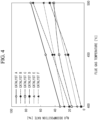
- Fig. 4 is a graph illustrating decomposition characteristics for nitrous oxide with respect to the temperature of the flue gas.
- Catalysts A to F illustrated in Fig. 4 correspond to catalysts A to F described in Examples of nitrogen oxide decomposition catalyst described later.
- the decomposition rate of nitrous oxide increases. Therefore, when ammonia is decomposed by the ammonia decomposition catalyst of the ammonia decomposition unit 10 to increase the temperature of the flue gas, the decomposition rate of nitrous oxide increases with the rise in temperature of the flue gas.
- Fig. 5 is a graph illustrating decomposition characteristics for NO with respect to the temperature of the flue gas.
- Catalysts A to F illustrated in Fig. 5 correspond to catalysts A to F described in Examples of nitrogen oxide decomposition catalyst described later.
- the decomposition rate of NO increases. Therefore, when ammonia is decomposed by the ammonia decomposition catalyst of the ammonia decomposition unit 10 to increase the temperature of the flue gas, the decomposition rate of NO increases with the rise in temperature of the flue gas.
- the reason why the ammonia decomposition unit 10 is installed upstream of the nitrogen oxide decomposition unit 20 is that the supply amount of unburned ammonia contained in the flue gas from the combustion device 200 is assumed to be larger than the amount of ammonia required to decompose nitrous oxide and NOx in the nitrogen oxide decomposition unit 20.
- the flue gas treatment device 100 of the present embodiment decomposes excessive ammonia in the ammonia decomposition unit 10, increases the temperature of the flue gas by using heat generated in the decomposition of ammonia, and thereby increases the decomposition rate of nitrous oxide and NOx in the nitrogen oxide decomposition unit 20.
- the amount of the flue gas from the flue gas treatment device 100 or the amount of ammonia contained in the flue gas is smaller than expected, the whole amount of unburned ammonia is decomposed in the ammonia decomposition unit 10, and ammonia required as the reducing agent in the nitrogen oxide decomposition unit 20 will be insufficient. Accordingly, in the present embodiment, when ammonia required as the reducing agent in the nitrogen oxide decomposition unit 20 becomes insufficient, a reducing agent is supplied from the first supply unit 50 to compensate for the shortage of ammonia in the nitrogen oxide decomposition unit 20.
- Fig. 6 is a flowchart illustrating the process of supplying a reducing agent in the flue gas treatment device 100 of the present embodiment.
- the process of each step of Fig. 6 is performed by the control unit 80 controlling each unit of the flue gas treatment device 100.
- the process of the present flowchart is started.
- step S108 since the temperature Ta of the flue gas flowing through the pipe L2 is lower than the supply ready temperature at which the reducing agent is ready to be supplied to the nitrogen oxide decomposition unit 20, the control unit 80 performs control to stop supply of the reducing agent from the first supply unit 50.
- step S102 the control unit 80 determines whether or not the NOx concentration determined by the detection unit 40 is lower than or equal to a first predetermined concentration (for example, 200 ppm). If the determination is YES, the control unit 80 proceeds with the process to step S103, and if the determination is NO, the control unit 80 proceeds with the process to step S105.
- a first predetermined concentration for example, 200 ppm
- step S104 since the NOx concentration is lower than or equal to the first predetermined concentration and the nitrous oxide concentration is lower than or equal to the second predetermined concentration, the control unit 80 determines that the reduction treatment on NOx and nitrous oxide by ammonia has been suitably performed and controls the first supply unit 50 to reduce the amount of reducing agent supply.
- step S106 the control unit 80 determines whether or not the combustion device 200 is stopped. If the determination is YES, the control unit 80 proceeds with the process to step S107, and if the determination is NO, the control unit 80 performs step S101 again.
- the combustion device 200 transmits the operation state including the combustion operation stop state to the control unit 80.
- the first component and the second component obtained in Example 1 were used, the amounts of water addition during slurry preparation were changed to 476 and 816 kg, respectively, the obtained slurry was carried by a paper honeycomb carrier (product name: HONEYCLE 3319, 150 mm x 150 mm square, 50 mm in length, manufactured by NICHIAS Corporation) in the same manner as in Example 1, and thereby catalysts of the present Examples were obtained.
- the first component / second component ratio between the first component and the second component in the present catalysts were 1/99, and the Pt content in the catalyst component corresponded to 5 ppm.
- the amounts of the coated catalyst of Examples 3 to 5 were 100, 80, and 50 g/m 2 per carrier surface area, respectively, for the first component and the second component in combination.
- a catalyst of the present Example was obtained in the same manner as in Example 1 except that the paper honeycomb carrier of Example 1 was changed to a metal lath (SUS304, 0.2 mmt in plate thickness, 150 mm x 150 mm square).
- the first component / second component ratio between the first component and the second component in the present catalyst was 1/99, and the Pt content in the catalyst component corresponded to 5 ppm.
- the amount of the coated catalyst was 200 g/m 2 per carrier surface area for the first component and the second component in combination.
- the nitrogen oxide decomposition catalyst of the nitrogen oxide decomposition unit 20 of the present embodiment is any of the following catalysts A to E, for example.
- an aqueous solution containing 13.2 g of iron (III) nitrate nonahydrate (Fe 2 (NO 3 ) 3 ⁇ 9H 2 O) heated at 80 °C, then the mixture was stirred for 3 hours while maintained at a temperature of 80 °C, and thereby slurry was obtained.
- the slurry was filtrated with use of a suction funnel to which filter paper (No. 5C) was attached.
- a predetermined amount of pure water was poured to the cake on the filter paper to wash the cake.
- the washed cake was dried at 110 °C for 12 hours and sintered at 500 °C for 5 hours.
- the sintered product was pulverized by a planetary ball mill to obtain powder.
- This powder was put into 2000 ml of an aqueous solution containing 13.2 g of iron (III) nitrate nonahydrate (Fe 2 (NO 3 ) 3 ⁇ 9H 2 O), the above operation was performed another two times (in total three times of the ion exchange step), and thereby a powder Fe-carrying zeolite catalyst D was obtained.
- a honeycomb catalyst D was obtained by the same manufacturing method as for the catalyst A except that the Fe-carrying zeolite catalyst A was replaced with the Fe-carrying zeolite catalyst D.
- ammonia contained in a flue gas from the combustion device 200 is suitably decomposed by an ammonia decomposition catalyst when passing through the ammonia decomposition unit 10. Further, nitrous oxide and NOx produced when ammonia is combusted in the combustion device 200 are suitably decomposed by a nitrogen oxide decomposition catalyst when passing through the nitrogen oxide decomposition unit 20. As described above, according to the flue gas treatment device 100 of the present disclosure, ammonia and nitrous oxide contained in a flue gas from the combustion device 200 that combusts fuel containing ammonia can be suitably decomposed.
- the flue gas treatment device 100 of the present embodiment even when ammonia remains in the flue gas that has passed through the nitrogen oxide decomposition unit 20, ammonia is decomposed in the ammonia decomposition unit 30, and this can prevent ammonia from being exhausted externally.
- a reducing agent is supplied from the first supply unit 50 into the flue gas supplied to the nitrogen oxide decomposition unit 20 in order to compensate for shortage of ammonia used for reducing nitrous oxide and NOx.
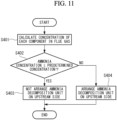
- step S302 based on the load of the combustion device 200, the control unit 80 calculates the concentration of each component of ammonia, nitrous oxide, and NOx in the flue gas from the combustion device 200.
- the combustion device 200 transmits the load of the combustion operation to the control unit 80.
- the control unit 80 stores in advance a map of the concentration of each component of ammonia, nitrous oxide, and NOx in association with a plurality of loads of the combustion device 200, respectively, in a storage unit (not illustrated).
- the control unit 80 calculates the concentration in association with a load transmitted from the combustion device 200 with reference to the map stored in the storage unit.
- step S303 the control unit 80 determines whether or not the ammonia concentration calculated in step S302 is lower than or equal to a predetermined concentration. If the determination is YES, the control unit 80 proceeds with the process to step S304, and if the determination is NO, the control unit 80 proceeds with the process to step S305.
- the predetermined concentration is a concentration expressed by the following formula (12). ⁇ ⁇ nitrous oxide concentration + ⁇ ⁇ NOx concentration
- step S406 the control unit 80 determines whether or not the NOx concentration determined by the detection unit 40 is lower than or equal to a first predetermined concentration (for example, 200 ppm). If the determination is YES, the control unit 80 proceeds with the process to step S407, and if the determination is NO, the control unit 80 proceeds with the process to step S414.
- a first predetermined concentration for example, 200 ppm
- ammonia or urea water is supplied into a flue gas supplied from the combustion device 200 to the ammonia decomposition unit 10, and thereby an exothermic reaction due to oxidization of ammonia in the ammonia decomposition unit 10 can be promoted. Accordingly, the temperature of the flue gas guided from the ammonia decomposition unit 10 to the nitrogen oxide decomposition unit 20 can be suitably increased to operate the nitrogen oxide decomposition unit 20 within a temperature range that does not cause a change in the decomposition rate of nitrous oxide due to the concentration of NO contained in the flue gas.
- the predetermined temperature is higher than or equal to 450 °C and lower than or equal to 530 °C, and thereby the nitrogen oxide decomposition unit 20 can be operated within a suitable temperature range that does not cause a change in the decomposition rate of nitrous oxide due to the concentration of NO contained in the flue gas.
- step S414 an amount of the reducing agent required for reducing NOx and nitrous oxide is calculated with respect to the NOx concentration and the nitrous oxide concentration calculated in step S302 of Fig. 9 , and the coefficient 7 multiplied by the required amount of the reducing agent is set to a value larger than that in the fifth embodiment (for example, 1.5).
- the flue gas treatment device and the design method of a flue gas treatment device according to each embodiment described above are understood as follows, for example.
- a flue gas treatment device (100) is a flue gas treatment device (100, 100A) configured to treat a flue gas from a combustion device (200) that combusts fuel containing ammonia, and the flue gas treatment device includes: a first treatment unit (10) having a first catalyst that decomposes ammonia contained in the flue gas; and a second treatment unit (20) having a second catalyst that decomposes nitrous oxide and NOx contained in the flue gas in which ammonia was decomposed by the first treatment unit.
- the flue gas treatment device may be configured such that the first treatment unit removes, by the first catalyst, NOx produced when ammonia contained in the flue gas is decomposed.
- NOx contained in the flue gas from the combustion device can be suitably prevented from increasing when passing through the first treatment unit.
- the flue gas treatment device may be configured to include: a bypass pipe (L7) configured to guide, to the second treatment unit, the flue gas from the combustion device without causing the flue gas to pass through the first treatment unit; and a bypass valve (90) arranged on the bypass pipe.
- a bypass pipe L7 configured to guide, to the second treatment unit, the flue gas from the combustion device without causing the flue gas to pass through the first treatment unit
- a bypass valve (90) arranged on the bypass pipe.
- the bypass valve is closed, and thereby excessive ammonia can be decomposed in the first treatment unit.
- the concentration of ammonia contained in the flue gas from the combustion device is lower than or equal to the concentration required as a reducing agent when nitrous oxide and NOx are decomposed in the second treatment unit, the bypass valve is opened, and thereby ammonia can be guided to the second treatment unit without being decomposed in the first treatment unit.
- the flue gas treatment device may be configured to include a third treatment unit (30) configured to decompose ammonia contained in the flue gas that passed through the second treatment unit.
- the flue gas treatment device may be configured to include: a detection unit (40) configured to determine a concentration of nitrous oxide and/or NOx contained in the flue gas that passed through the second treatment unit; and a first supply unit (50) configured to supply ammonia or urea water into the flue gas supplied from the first treatment unit to the second treatment unit when the concentration of nitrous oxide contained in the flue gas is higher than a first predetermined concentration or the concentration of NOx contained in the flue gas is higher than a second predetermined concentration, and the second catalyst is a catalyst that reduces and decomposes nitrous oxide and NOx contained in the flue gas by ammonia.
- the detection unit determines that the concentration of nitrous oxide contained in the flue gas that has passed through the second treatment unit is higher than the first predetermined concentration or that the concentration of NOx contained in the flue gas that has passed through the second treatment unit is higher than the second predetermined concentration
- ammonia or urea water is supplied as a reducing agent from the first supply unit into the flue gas supplied to the second treatment unit in order to compensate for shortage of ammonia used for reducing nitrous oxide and NOx.
- the shortage of ammonia supplied from the first treatment unit to the second treatment unit is compensated, and the concentration of nitrous oxide and the concentration of NOx contained in the flue gas that has passed through the second treatment unit can be reduced.
- the flue gas treatment device may be configured to include: a temperature detection unit configured to determine a temperature of the flue gas from the first treatment unit; and a second supply unit (55) configured to supply ammonia or urea water into the flue gas supplied from the combustion device to the first treatment unit when the temperature determined by the temperature detection unit is lower than or equal to a predetermined temperature.
- the flue gas treatment device of the present configuration ammonia or urea water is supplied into the flue gas supplied from the combustion device to the first treatment unit, and thereby an exothermic reaction due to decomposition of ammonia in the first treatment unit can be promoted. Accordingly, the temperature of the flue gas guided from the first treatment unit to the second treatment unit can be suitably increased to operate the nitrogen oxide decomposition unit within a temperature range that does not cause a change in the decomposition rate of nitrous oxide due to the concentration of NO contained in the flue gas.
- the flue gas treatment device may be configured to include a third treatment unit (30) configured to decompose ammonia contained in the flue gas that passed through the second treatment unit.
- the nitrogen oxide decomposition unit can be operated within a suitable temperature range that does not cause a change in the decomposition rate of nitrous oxide due to the concentration of NO contained in the flue gas.
- the flue gas treatment device is a flue gas treatment device (100B) configured to treat a flue gas from a combustion device that combusts fuel containing ammonia
- the flue gas treatment device includes: a first supply unit (50) configured to supply ammonia as a reducing agent into the flue gas from the combustion device; a nitrogen oxide decomposition unit (20) having a decomposition catalyst that reduces nitrous oxide and NOx contained in the flue gas by ammonia supplied from the ammonia supply unit; and an ammonia decomposition unit (30) configured to decompose ammonia contained in the flue gas that passed through the nitrogen oxide decomposition unit.
- ammonia contained in a flue gas from the combustion device reacts with nitrous oxide and NOx as a reducing agent and is decomposed by a decomposition catalyst when passing through the nitrogen oxide decomposition unit. Further, nitrous oxide and NOx produced when ammonia is combusted in the combustion device are suitably decomposed by the decomposition catalyst when passing through the nitrogen oxide decomposition unit. In such a way, according to the flue gas treatment device of the present disclosure, ammonia, nitrous oxide, and NOx contained in a flue gas from the combustion device that combusts fuel containing ammonia can be suitably decomposed.
Landscapes
- Chemical & Material Sciences (AREA)
- Engineering & Computer Science (AREA)
- Chemical Kinetics & Catalysis (AREA)
- Environmental & Geological Engineering (AREA)
- Health & Medical Sciences (AREA)
- Oil, Petroleum & Natural Gas (AREA)
- General Chemical & Material Sciences (AREA)
- Biomedical Technology (AREA)
- Analytical Chemistry (AREA)
- Combustion & Propulsion (AREA)
- Mechanical Engineering (AREA)
- General Engineering & Computer Science (AREA)
- Toxicology (AREA)
- Materials Engineering (AREA)
- Organic Chemistry (AREA)
- Crystallography & Structural Chemistry (AREA)
- Exhaust Gas Treatment By Means Of Catalyst (AREA)
- Incineration Of Waste (AREA)
- Catalysts (AREA)
Abstract
Description
- The present disclosure relates to a flue gas treatment device and a design method of a flue gas treatment device.
- In recent years, to suppress global warming, carbon neutrality is required to achieve, and application of ammonia fuel is considered as fuel that does not discharge carbon dioxide during combustion. When ammonia fuel is used, since not only NOx but also ammonia (NH3), nitrous oxide (N2O), and the like will be contained in a flue gas, it is required to remove these components from the flue gas to reduce impact on the environment.
- Ammonia treatment devices that oxidize ammonia by using an ammonia decomposition catalyst and thereby decompose ammonia into nitrogen and water are conventionally known (for example, see Patent Literature 1).
- [PTL 1]
Japanese Patent Application Laid-Open No. 2006-26529 - With the art of Patent Literature 1, however, it is possible to decompose ammonia but not possible to decompose nitrous oxide when a gas to be treated contains nitrous oxide, for example.
- Further, it is conventionally known to employ a selective catalytic reduction (SCR) to reduce NOx by spraying ammonia or urea water, which is a reducing agent, into a flue gas in order to decompose NOx contained in the flue gas or the like exhausted from a combustion device. In the SCR, however, while it is possible to decompose NOx but not possible to decompose nitrous oxide.
- The present disclosure has been made in view of such circumstances and intends to provide a flue gas treatment device and a design method of a flue gas treatment device that can suitably decompose ammonia, nitrous oxide, and NOx contained in a flue gas from a combustion device that combusts fuel containing ammonia.
- To solve the above problems, the present disclosure employs the following solutions.
- A flue gas treatment device according to the present disclosure is a flue gas treatment device configured to treat a flue gas from a combustion device that combusts fuel containing ammonia, and the flue gas treatment device includes: a first treatment unit having a first catalyst that decomposes ammonia contained in the flue gas; and a second treatment unit having a second catalyst that decomposes nitrous oxide and NOx contained in the flue gas in which ammonia was decomposed by the first treatment unit.
- A design method of a flue gas treatment device according to the present disclosure is a design method of a flue gas treatment device configured to treat a flue gas from a combustion device that combusts fuel containing ammonia, and the design method includes: designing the flue gas treatment device such that, when an concentration of ammonia contained in the flue gas is higher than a sum concentration of a first concentration and a second concentration, a first treatment unit having a first catalyst that decomposes ammonia contained in the flue gas is arranged downstream of the combustion device, and a second treatment unit having a second catalyst that decomposes nitrous oxide and NOx contained in the flue gas in which ammonia was decomposed by the first treatment unit is arranged downstream of the first treatment unit, the first concentration being obtained by multiplying a concentration of nitrous oxide contained in the flue gas by a first coefficient, and the second concentration being obtained by multiplying a concentration of NOx contained in the flue gas by a second coefficient; and designing the flue gas treatment device such that, when the concentration of ammonia contained in the flue gas is lower than or equal to the sum concentration, the second treatment unit is arranged without the first treatment unit being arranged downstream of the combustion device.
- According to the present disclosure, it is possible to provide a flue gas treatment device and a design method of a flue gas treatment device that can suitably decompose ammonia, nitrous oxide, and NOx contained in a flue gas from a combustion device that combusts fuel containing ammonia.
-
- [
Fig. 1 ]
Fig. 1 is a schematic configuration diagram illustrating a flue gas treatment device according to a first embodiment of the present disclosure. - [
Fig. 2 ]
Fig. 2 is a graph illustrating decomposition characteristics of an ammonia decomposition catalyst. - [
Fig. 3 ]
Fig. 3 is a graph illustrating a relationship between the ammonia concentration and rise in temperature in an ammonia decomposition catalyst. - [
Fig. 4 ]
Fig. 4 is a graph illustrating decomposition characteristics for nitrous oxide with respect to the temperature of a flue gas. - [
Fig. 5 ]
Fig. 5 is a graph illustrating decomposition characteristics for NO with respect to the temperature of a flue gas. - [
Fig. 6 ]
Fig. 6 is a flowchart illustrating a process of supplying a reducing agent in the flue gas treatment device according to the first embodiment of the present disclosure. - [
Fig. 7 ]
Fig. 7 is a flowchart illustrating a process of switching a bypass valve in the flue gas treatment device according to the first embodiment of the present disclosure. - [
Fig. 8 ]
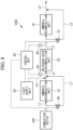
Fig. 8 is a schematic configuration diagram illustrating a flue gas treatment device according to a second embodiment of the present disclosure. - [
Fig. 9 ]
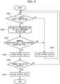
Fig. 9 is a flowchart illustrating a process of switching a bypass valve of the flue gas treatment device according to the second embodiment of the present disclosure. - [
Fig. 10 ]
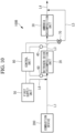
Fig. 10 is a schematic configuration diagram illustrating a flue gas treatment device according to a third embodiment of the present disclosure. - [
Fig. 11 ]
Fig. 11 is flowchart illustrating a design method of a flue gas treatment device according to a fourth embodiment of the present disclosure. - [
Fig. 12 ]
Fig. 12 is a schematic configuration diagram illustrating a flue gas treatment device according to a fifth embodiment of the present disclosure. - [
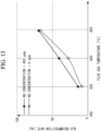
Fig. 13 ]
Fig. 13 is a graph illustrating a decomposition rate of nitrous oxide with respect to the temperature of a flue gas in a nitrogen oxide decomposition unit, which is a graph about comparison between a case where the NO concentration is 0 ppm and a case where the NO concentration is 450 ppm. - [
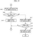
Fig. 14 ]
Fig. 14 is a flowchart illustrating a process of supplying fuel and a reducing agent in the flue gas treatment device according to the fifth embodiment of the present disclosure. - [
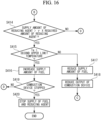
Fig. 15 ]
Fig. 15 is a flowchart illustrating the process of supplying fuel and a reducing agent in the flue gas treatment device according to the fifth embodiment of the present disclosure. - [
Fig. 16 ]
Fig. 16 is a flowchart illustrating the process of supplying fuel and a reducing agent in the flue gas treatment device according to the fifth embodiment of the present disclosure. - [
Fig. 17 ]
Fig. 17 is a schematic configuration diagram illustrating a flue gas treatment device according to a modified example for the fifth embodiment of the present disclosure. - A flue
gas treatment device 100 according to a first embodiment of the present disclosure will be described below with reference to the drawings. The fluegas treatment device 100 of the present embodiment is a device to treat a flue gas from acombustion device 200 that combusts fuel containing ammonia and reduce ammonia, nitrous oxide, and NOx exhausted externally. - The
combustion device 200 is a device that combusts fuel containing ammonia, for example, a marine diesel engine that generates propulsion of a ship. For example, thecombustion device 200 of the present embodiment co-combusts ammonia and other fuel (heavy oil, liquefied natural gas (LNG), liquefied petroleum gas (LPG)). Further, thecombustion device 200 may be a device that uses only ammonia as fuel, for example. - Since ammonia is used as fuel in the
combustion device 200, a flue gas from thecombustion device 200 contains unburned ammonia. Further, the flue gas from thecombustion device 200 contains NOx (NO, NO2) and nitrous oxide (N2O) produced from combustion of ammonia and other fuel. The fluegas treatment device 100 of the present embodiment reduces ammonia, NOx, and nitrous oxide contained in the flue gas from thecombustion device 200. -
Fig. 1 is a schematic configuration diagram illustrating the flue gas treatment device according to the first embodiment of the present disclosure. As illustrated inFig. 1 , the fluegas treatment device 100 of the present embodiment includes an ammonia decomposition unit (first treatment unit) 10, a nitrogen oxide decomposition unit (second treatment unit) 20, an ammonia decomposition unit (third treatment unit) 30, adetection unit 40, afirst supply unit 50 configured to supply ammonia or urea water that is a reducing agent, atemperature sensor 60, abypass valve 70, and acontrol unit 80. - A flue gas from the
combustion device 200 is supplied to theammonia decomposition unit 10 via a pipe L1. The flue gas that has passed through theammonia decomposition unit 10 is supplied to the nitrogenoxide decomposition unit 20 via a pipe L2. The flue gas that has passed through the nitrogenoxide decomposition unit 20 is supplied to theammonia decomposition unit 30 via a pipe L3. The flue gas that has passed through theammonia decomposition unit 30 is exhausted externally via a pipe L4. A part of the flue gas that has passed through the nitrogenoxide decomposition unit 20 is guided from the pipe L3 to the pipe L4 via the pipe L5 without passing through theammonia decomposition unit 30 when thebypass valve 70 is opened. - Although the flue
gas treatment device 100 of the present embodiment has the pipe L5 and thebypass valve 70, a modified example without these elements may be employed. In such a modified example, the whole amount of the flue gas that has passed through the nitrogenoxide decomposition unit 20 is guided to theammonia decomposition unit 30. - The
ammonia decomposition unit 10 has an ammonia decomposition catalyst (first catalyst) that decomposes ammonia contained in the flue gas from thecombustion device 200. The ammonia decomposition catalyst is a multi-functional catalyst having functions of not only decomposing ammonia but also decomposing NOx and suppressing production of nitrous oxide. The ammonia decomposition catalyst of the present embodiment is a catalyst consisting of: a first component that is silica and zeolite carrying one or more types of noble metals selected from platinum (Pt), palladium (Pd), iridium (Ir), and rhodium (Rh); and a second component that is a composition consisting of oxide of one or more elements selected from titanium (Ti), tungsten (W), and vanadium (V). Examples of the ammonia decomposition catalyst will be described later. - The ammonia decomposition catalyst of the
ammonia decomposition unit 10 decomposes NH3 in accordance with the following formulae (1) and (2) because of the presence of the first component.
4NH3 + 3O2 → 2N2 + 6H2O (1)
4NH3 + 5O2 → 4NO + 6H2O (2)
- Further, the ammonia decomposition catalyst of the
ammonia decomposition unit 10 decomposes NH3 and removes at least a part of NO by-produced in formula (2) in accordance with the following formula (3) because of the presence of the second component.
4NH3 + 4NO + O2 → 4N2 + 6H2O (3)
- Further, in the ammonia decomposition catalyst of the
ammonia decomposition unit 10, it is estimated that nitrous oxide (N2O) is produced in accordance with formula (5) from NO2 produced by oxidization of NH3 in accordance with formula (4). In the ammonia decomposition catalyst, a small amount of a noble metal catalyst is present uniformly on a denitration catalyst. Thus, NO2 produced on the noble metal catalyst, together with NO produced in formula (2), immediately reacts on the denitration catalyst into N2 as in formula (6) with a high probability, and this can reduce by-production of N2O.
4NH3 + 7O2 → 4NO2 + 6H2O (4)
4NH3 + 4NO2 + O2 → 4N2O + 6H2O (5)
NO + NO2 + 2NH3 → 2N2 +3H2O (6)
- The nitrogen
oxide decomposition unit 20 has a nitrogen oxide decomposition catalyst (second catalyst) that decomposes nitrous oxide and NOx contained in the flue gas in which ammonia has been decomposed by theammonia decomposition unit 10. The nitrogen oxide decomposition catalyst contains a carrier containing SiO2 and Al2O3 and iron element carried thereby. In the carrier, SiO2 and Al2O3 may be contained as a mixture or may be contained as a composite. The composite of SiO2 and Al2O3 may be, for example, aluminosilicate (xM2O·yAl2O3·zSiO2·nH2O) or the like. Examples of the nitrogen oxide decomposition catalyst will be described later. - The nitrogen oxide decomposition catalyst of the nitrogen
oxide decomposition unit 20 decomposes nitrous oxide via a reduction reaction with NH3 in accordance with the following formula (7).
3N2O + 2NH3 → 4N2 + 3H2O (7)
- The nitrogen oxide decomposition catalyst of the nitrogen
oxide decomposition unit 20 decomposes NOx via a reduction reaction with NH3 in accordance with the following formulae (8), (9), (10).
4NO + 4NH3 + O2 → 4N2 + 6H2O (8)
NO + NO2 + 2NH3 → 2N2 + 3H2O (9)
6NO2 + 8NH3 → 7N2 + 12H2O (10)
- The
ammonia decomposition unit 30 has an ammonia decomposition catalyst (third catalyst) that decomposes ammonia contained in the flue gas that has passed through the nitrogenoxide decomposition unit 20. The ammonia decomposition catalyst is a multi-functional catalyst having functions of not only decomposing ammonia but also decomposing NOx and suppressing production of nitrous oxide. The ammonia decomposition catalyst is a catalyst consisting of: a first component that is silica and zeolite carrying one or more types of noble metals selected from platinum (Pt), palladium (Pd), iridium (Ir), and rhodium (Rh); and a second component that is a composition consisting of oxide of one or more elements selected from titanium (Ti), tungsten (W), and vanadium (V). Since the configuration of theammonia decomposition unit 30 is the same as the configuration of theammonia decomposition unit 10, the description thereof will be omitted below. - The
detection unit 40 is a device that determines concentrations of nitrous oxide and NOx contained in a flue gas that has passed through theammonia decomposition unit 10. Thedetection unit 40 determines the concentrations of nitrous oxide and NOx contained in the flue gas passing through the pipe L3. The concentrations of nitrous oxide and NOx determined by thedetection unit 40 are transmitted to thecontrol unit 80. - The
first supply unit 50 is a device that supplies ammonia or urea water, which is a reducing agent, into the flue gas supplied from theammonia decomposition unit 10 to the nitrogenoxide decomposition unit 20. Thefirst supply unit 50 supplies a reducing agent to the pipe L2 via a pipe L6 and mixes the reducing agent with the flue gas flowing through the pipe L2. For example, a reducing agent is sprayed by the pipe L6 into the pipe L2, and thereby the reducing agent is mixed with the flue gas. Thefirst supply unit 50 adjusts the supply amount of the reducing agent supplied to the pipe L2 in accordance with a control signal transmitted from thecontrol unit 80. - When urea water is supplied as the reducing agent, the urea water mixed with the flue gas in the pipe L2 is hydrolyzed in the flue gas, and thereby ammonia is produced. The nitrogen oxide decomposition catalyst of the nitrogen
oxide decomposition unit 20 then decomposes NOx via a reduction reaction with ammonia (NH3) in accordance with formulae (7), (8), (9) described above. - The
temperature sensor 60 is a device that determines the temperature of a flue gas flowing through the pipe L2. Thetemperature sensor 60 transmits the determined flue gas temperature to thecontrol unit 80. - The
bypass valve 70 is an on-off valve arranged on the pipe L5. The open/close state of thebypass valve 70 is controlled by thecontrol unit 80. When thebypass valve 70 is in an open state, the flue gas is guided from the pipe L3 to the pipe L4 via the pipe L5. When thebypass valve 70 is in a closed state, the flue gas is not guided to the pipe L5, and the whole amount of the flue gas flowing through the pipe L3 is guided to the pipe L4 via theammonia decomposition unit 30. - The
control unit 80 is a device that controls each unit of the fluegas treatment device 100. Thecontrol unit 80 controls each unit of the fluegas treatment device 100 by reading and executing a control program stored in a storage unit (not illustrated). - The
control unit 80 controls the supply amount of the reducing agent, which is supplied by thefirst supply unit 50 to the pipe L2, in accordance with the concentrations of nitrous oxide and NOx determined by thedetection unit 40 and the temperature of the flue gas determined by thetemperature sensor 60. Further, thecontrol unit 80 controls the open/close state of thebypass valve 70 in accordance with the concentrations of nitrous oxide and NOx determined by thedetection unit 40 and the temperature of the flue gas determined by thetemperature sensor 60. - Next, the decomposition characteristics of the ammonia decomposition catalyst of the
ammonia decomposition unit 10 of the present embodiment will be described with reference toFig. 2. Fig. 2 is a graph illustrating the decomposition characteristics of the ammonia decomposition catalyst. As illustrated inFig. 2 , as the temperature of the flue gas containing ammonia rises from 350 °C to 450 °C, the ammonia decomposition rate [%] due to the ammonia decomposition catalyst of theammonia decomposition unit 10 increases. - Next, the relationship between the ammonia concentration and the rise in temperature in the ammonia decomposition catalyst of the
ammonia decomposition unit 10 of the present embodiment will be described with reference toFig. 3. Fig. 3 is a graph illustrating the relationship between the ammonia temperature and the rise in temperature in the ammonia decomposition catalyst. - As illustrated in
Fig. 3 , in the ammonia decomposition catalyst of theammonia decomposition unit 10, as the concentration of unburned ammonia contained in the flue gas from thecombustion device 200 increases, the rise in temperature of the flue gas increases due to heat generated during decomposition of ammonia. Combustion of unburned ammonia with the ammonia decomposition catalyst of theammonia decomposition unit 10 can increase the temperature of theammonia decomposition unit 10 and thereby increase the ammonia decomposition rate. Further, the temperature of the flue gas from theammonia decomposition unit 10 can be increased. - Next, the decomposition characteristics for nitrous oxide with respect to the temperature of a flue gas will be described with reference to
Fig. 4. Fig. 4 is a graph illustrating decomposition characteristics for nitrous oxide with respect to the temperature of the flue gas. Catalysts A to F illustrated inFig. 4 correspond to catalysts A to F described in Examples of nitrogen oxide decomposition catalyst described later. As illustrated inFig. 4 , for all the catalysts A to F, as the temperature of the flue gas increases, the decomposition rate of nitrous oxide increases. Therefore, when ammonia is decomposed by the ammonia decomposition catalyst of theammonia decomposition unit 10 to increase the temperature of the flue gas, the decomposition rate of nitrous oxide increases with the rise in temperature of the flue gas. - Next, the decomposition characteristics for NO with respect to the temperature of a flue gas will be described with reference to
Fig. 5. Fig. 5 is a graph illustrating decomposition characteristics for NO with respect to the temperature of the flue gas. Catalysts A to F illustrated inFig. 5 correspond to catalysts A to F described in Examples of nitrogen oxide decomposition catalyst described later. As illustrated inFig. 5 , for all the catalysts A to F, as the temperature of the flue gas increases, the decomposition rate of NO increases. Therefore, when ammonia is decomposed by the ammonia decomposition catalyst of theammonia decomposition unit 10 to increase the temperature of the flue gas, the decomposition rate of NO increases with the rise in temperature of the flue gas. - In the present embodiment, the reason why the
ammonia decomposition unit 10 is installed upstream of the nitrogenoxide decomposition unit 20 is that the supply amount of unburned ammonia contained in the flue gas from thecombustion device 200 is assumed to be larger than the amount of ammonia required to decompose nitrous oxide and NOx in the nitrogenoxide decomposition unit 20. The fluegas treatment device 100 of the present embodiment decomposes excessive ammonia in theammonia decomposition unit 10, increases the temperature of the flue gas by using heat generated in the decomposition of ammonia, and thereby increases the decomposition rate of nitrous oxide and NOx in the nitrogenoxide decomposition unit 20. - The flue
gas treatment device 100 of the present embodiment assumes that the concentrations of ammonia, nitrous oxide, and NOx contained in the flue gas from thecombustion device 200 satisfy the following formula (11), respectively.
- Herein, α and β are coefficients, for example, α = 1.0 and β = 1.5. The coefficient α = 1.0 is based on the value obtained by multiplying the molar ratio of ammonia / nitrous oxide in the reaction of formula (7) (ammonia / nitrous oxide = 2/3) by 1.5. The coefficient β = 1.5 is based on the value obtained by multiplying the molar ratio of ammonia / NO in the reaction of formula (8) (ammonia / NO = 1/1) by 1.5. Note that the numerical values multiplied by α, β are not limited to 1.5 and may be set to any numerical value greater than or equal to 1.2 and less than or equal to 2.0 in accordance with the property of the flue gas from the
combustion device 200, for example. - However, for example, when the amount of the flue gas from the flue
gas treatment device 100 or the amount of ammonia contained in the flue gas is smaller than expected, the whole amount of unburned ammonia is decomposed in theammonia decomposition unit 10, and ammonia required as the reducing agent in the nitrogenoxide decomposition unit 20 will be insufficient. Accordingly, in the present embodiment, when ammonia required as the reducing agent in the nitrogenoxide decomposition unit 20 becomes insufficient, a reducing agent is supplied from thefirst supply unit 50 to compensate for the shortage of ammonia in the nitrogenoxide decomposition unit 20. - Next, a process of supplying a reducing agent in the flue
gas treatment device 100 of the present embodiment will be described with reference toFig. 6. Fig. 6 is a flowchart illustrating the process of supplying a reducing agent in the fluegas treatment device 100 of the present embodiment. The process of each step ofFig. 6 is performed by thecontrol unit 80 controlling each unit of the fluegas treatment device 100. In response to start of a combustion operation by thecombustion device 200, the process of the present flowchart is started. - In step S101, the
control unit 80 determines whether or not the temperature Ta of a flue gas flowing through the pipe L2 transmitted from thetemperature sensor 60 is higher than or equal to a supply ready temperature (for example, 350 °C) at which a reducing agent is ready to be supplied to the nitrogenoxide decomposition unit 20. If the determination is YES, thecontrol unit 80 proceeds with the process to step S102, and if the determination is NO, thecontrol unit 80 proceeds with the process to step S108. - In step S108, since the temperature Ta of the flue gas flowing through the pipe L2 is lower than the supply ready temperature at which the reducing agent is ready to be supplied to the nitrogen
oxide decomposition unit 20, thecontrol unit 80 performs control to stop supply of the reducing agent from thefirst supply unit 50. - In step S102, the
control unit 80 determines whether or not the NOx concentration determined by thedetection unit 40 is lower than or equal to a first predetermined concentration (for example, 200 ppm). If the determination is YES, thecontrol unit 80 proceeds with the process to step S103, and if the determination is NO, thecontrol unit 80 proceeds with the process to step S105. - In step S103, the
control unit 80 determines whether or not the nitrous oxide concentration determined by thedetection unit 40 is lower than or equal to a second predetermined concentration (for example, 50 ppm). If the determination is YES, thecontrol unit 80 proceeds with the process to step S104, and if the determination is NO, thecontrol unit 80 proceeds with the process to step S105. - In step S104, since the NOx concentration is lower than or equal to the first predetermined concentration and the nitrous oxide concentration is lower than or equal to the second predetermined concentration, the
control unit 80 determines that the reduction treatment on NOx and nitrous oxide by ammonia has been suitably performed and controls thefirst supply unit 50 to reduce the amount of reducing agent supply. - In step S105, since the NOx concentration is higher than the first predetermined concentration or the nitrous oxide concentration is higher than the second predetermined concentration, the
control unit 80 determines that the reduction treatment on NOx and nitrous oxide by ammonia is not sufficiently performed, controls thefirst supply unit 50 to increase the amount of reducing agent supply, and proceeds with the process to step S101. - In step S106, the
control unit 80 determines whether or not thecombustion device 200 is stopped. If the determination is YES, thecontrol unit 80 proceeds with the process to step S107, and if the determination is NO, thecontrol unit 80 performs step S101 again. Thecombustion device 200 transmits the operation state including the combustion operation stop state to thecontrol unit 80. - In step S107, since the
combustion device 200 is stopped, thecontrol unit 80 determines that the reduction treatment on NOx and nitrous oxide by ammonia is unnecessary, stops supply of the reducing agent from thefirst supply unit 50, and ends the process of the present flowchart. In response to thecombustion device 200 starting a combustion operation, thecontrol unit 80 restarts the process of the present flowchart. - Next, a process of switching the
bypass valve 70 in the fluegas treatment device 100 of the present embodiment will be described with reference toFig. 7. Fig. 7 is a flowchart illustrating the process of switching thebypass valve 70 in the fluegas treatment device 100 of the present embodiment. The process of each step ofFig. 7 is performed by thecontrol unit 80 controlling each unit of the fluegas treatment device 100. In response to start of a combustion operation by thecombustion device 200, the process of the present flowchart is started. - In the flue
gas treatment device 100 of the present embodiment, theammonia decomposition unit 30 is arranged downstream of the nitrogenoxide decomposition unit 20. Theammonia decomposition unit 30 is provided for ensuring decomposition of excessive ammonia and preventing discharge of ammonia to outside when the concentration of ammonia contained in the flue gas from thecombustion device 200 is higher than an expected concentration and ammonia is not completely decomposed in theammonia decomposition unit 10 and the nitrogenoxide decomposition unit 20, for example. - In the
ammonia decomposition unit 30, however, when the concentration of ammonia contained in the flue gas from the nitrogenoxide decomposition unit 20 is lower than or equal to a predetermined acceptable concentration, it is not necessary to treat the flue gas in theammonia decomposition unit 30, and the flue gas will cause a pressure loss when passing through theammonia decomposition unit 30. Accordingly, in the present embodiment, when the concentration of ammonia contained in the flue gas from the nitrogenoxide decomposition unit 20 is lower than or equal to a predetermined acceptable concentration, a part of the flue gas from the nitrogenoxide decomposition unit 20 is guided to the pipe L5 to prevent a pressure loss from occurring when the flue gas passes through theammonia decomposition unit 30. - In step S201, the
control unit 80 determines whether or not the temperature Ta of a flue gas flowing through the pipe L2 transmitted from thetemperature sensor 60 is higher than or equal to a supply ready temperature (for example, 350 °C) at which a reducing agent is ready to be supplied to the nitrogenoxide decomposition unit 20. If the determination is YES, thecontrol unit 80 proceeds with the process to step S203, and if the determination is NO, thecontrol unit 80 proceeds with the process to step S202. - In step S202, since the temperature Ta of the flue gas flowing through the pipe L2 is lower than the supply ready temperature at which the reducing agent is ready to be supplied to the nitrogen
oxide decomposition unit 20 and the temperature of the flue gas from thecombustion device 200 has not yet increased to a suitable temperature, thecontrol unit 80 controls thebypass valve 70 into the closed state. - In step S203, the
control unit 80 determines whether or not the load of thecombustion device 200 is lower than or equal to a predetermined load (for example, 50% load). If the determination is YES, thecontrol unit 80 proceeds with the process to step S204, and if the determination is NO, thecontrol unit 80 performs step S201 again. Thecombustion device 200 transmits the load of the combustion operation to thecontrol unit 80. - In step S204, since the load of the
combustion device 200 is lower than or equal to the predetermined load, thecontrol unit 80 controls thebypass valve 70 into the open state. When the load of thecombustion device 200 is lower than or equal to the predetermined load, the concentration of ammonia contained in the flue gas from the nitrogenoxide decomposition unit 20 is lower than or equal to a predetermined acceptable concentration (for example, 5 ppm), and it is not necessary to treat the flue gas in theammonia decomposition unit 30. Accordingly, to reduce generation of a pressure loss caused when the flue gas passes through theammonia decomposition unit 30, a part of the flue gas flowing through the pipe L3 is guided from the pipe L5 to the pipe L4. - In step S205, the
control unit 80 determines whether or not thecombustion device 200 is stopped. If the determination is YES, thecontrol unit 80 proceeds with the process to step S206, and if the determination is NO, thecontrol unit 80 performs step S201 again. Thecombustion device 200 transmits the operation state including the combustion operation stop state to thecontrol unit 80. - In step S206, since the
combustion device 200 is stopped, thecontrol unit 80 closes thebypass valve 70 and ends the process of the present flowchart. In response to thecombustion device 200 starting a combustion operation, thecontrol unit 80 restarts the process of the present flowchart. - Although the
detection unit 40 determines the concentrations of nitrous oxide and NOx contained in the flue gas that has passed through theammonia decomposition unit 10 in the above description, other forms may be employed. Thedetection unit 40 may be to determine the concentration of either nitrous oxide or NOx contained in the flue gas that has passed through theammonia decomposition unit 10. When thedetection unit 40 determines the concentration of nitrous oxide, the process of step S102 ofFig. 6 is omitted. Further, when thedetection unit 40 determines the concentration of NOx, the process of step S103 ofFig. 6 is omitted. - The ammonia decomposition catalyst of the
ammonia decomposition unit 10 of the present embodiment is obtained by any of the following Examples, for example. - First, 100 g of fine silica powder (Tomita Pharmaceuticals, silicic acid anhydride) was added to 1 litter, 1.33 x 10⁻² wt% of chloroplatinic acid (H2[PtCl6]·6H2O) aqueous solution, the mixture was evaporated to dryness on a sand bath and sintered in air at 500 °C for 2 hours to prepare 0.05 wt% of Pt·SiO2, and thereby catalyst composition powder of the first component was obtained.
- On the other hand, 7.43 kg of ammonium paratungstate ((NH4)10·W12O41·5H2O) and 3.0 kg of ammonium metavanadate were added to 46.7 kg of titanium dioxide powder (product name, MCH, SO4 content: 3 wt%, manufactured by Ishihara Sangyo Co.), the mixture was kneaded by using a kneader, and the obtained paste was dried after granulation and sintered at 550 °C for 2 hours. The obtained granules were pulverized, and thereby catalyst composition powder of the second component was obtained. The composition is Ti/W/V = 91/5/4 (atom ratio).
- After slurry obtained by suspending 20 g of the first component and 2.02 kg of the second component in 3.06 kg of water was immersed in a paper honeycomb carrier (product name:
HONEYCLE 3722, 150 mm x 150 mm square, 50 mm in length, manufactured by NICHIAS Corporation) to impregnate the carrier with the slurry, the liquid was removed by air blow, and thereby the catalyst of the present Example was obtained. This catalyst was air-dried in the atmosphere for 12 hours and then sintered at 500 °C for 2 hours. The first component / second component ratio between the first component and the second component in the present catalyst was 1/99 (weight ratio, the same applies hereafter), the Pt content in the catalyst component corresponded to 5 ppm, and the amount of the coated catalyst was 150 g/m2 per carrier surface area for the first component and the second component in combination. Pieces of 5 levels x 8 cells (11 x 14 mm) and 50 mm in length were cut out from the obtained honeycomb catalyst to obtain test pieces. - A catalyst of the present Example was obtained in the same manner as in Example 1 except that the amounts of the first component, the second component, and water of Example 1 were changed to 10 g, 2.02 kg, and 3.04 kg, respectively. The first component / second component ratio between the first component and the second component in the present catalyst was 0.5/99.5, the Pt content in the catalyst component corresponded to 2.5 ppm, and the amount of the carried catalyst was 150 g/m2 per carrier surface area for the first component and the second component in combination.
- The first component and the second component obtained in Example 1 were used, the amounts of water addition during slurry preparation were changed to 476 and 816 kg, respectively, the obtained slurry was carried by a paper honeycomb carrier (product name:
HONEYCLE 3319, 150 mm x 150 mm square, 50 mm in length, manufactured by NICHIAS Corporation) in the same manner as in Example 1, and thereby catalysts of the present Examples were obtained. The first component / second component ratio between the first component and the second component in the present catalysts were 1/99, and the Pt content in the catalyst component corresponded to 5 ppm. The amounts of the coated catalyst of Examples 3 to 5 were 100, 80, and 50 g/m2 per carrier surface area, respectively, for the first component and the second component in combination. - A catalyst of the present Example was obtained in the same manner as in Example 1 except that the paper honeycomb carrier of Example 1 was changed to a metal lath (SUS304, 0.2 mmt in plate thickness, 150 mm x 150 mm square). The first component / second component ratio between the first component and the second component in the present catalyst was 1/99, and the Pt content in the catalyst component corresponded to 5 ppm. The amount of the coated catalyst was 200 g/m2 per carrier surface area for the first component and the second component in combination.
- A catalyst of the present Example was obtained in the same manner as above except that the water for preparing the slurry of Example 1 was changed to colloidal silica (product name: OS sol, SiO2 content: 20%, manufactured by Nissan Chemical Co.) / water = 3/7.
- After 20 g of the first component prepared in Example 1 is suspended in 1000 g of a liquid of colloidal silica / water = 3/7 and this was immersed in a paper honeycomb carrier to impregnate the carrier with the slurry, the liquid was removed by air blow, and the remaining was air-dried in the atmosphere for 12 hours and then sintered at 500 °C for 2 hours. The obtained catalyst was immersed in the slurry obtained by suspending 2.02 kg of the second component of Example 1 in 3.06 kg of water, the liquid was then removed, the remaining was then air-dried and sintered at 500 °C for 2 hours, and thereby the catalyst of the present Example was prepared.
- The nitrogen oxide decomposition catalyst of the nitrogen
oxide decomposition unit 20 of the present embodiment is any of the following catalysts A to E, for example. - First, 60 g of BEA type zeolite (SiO2/Al2O3 ratio = 25) was put into 2000 ml of an aqueous solution containing 13.2 g of iron (III) nitrate nonahydrate (Fe2(NO2)2·9H2O) heated at 80 °C, then the mixture was stirred for 3 hours while maintained at a temperature of 80 °C, and thereby slurry was obtained. Dehydration was performed on the slurry with use of a suction funnel to which filter paper (No. 5C) was attached. A predetermined amount of pure water was poured to the cake on the filter paper to wash the cake. The washed cake was dried at 110 °C for 12 hours and sintered at 500 °C for 5 hours. The sintered product was pulverized by a planetary ball mill, and thereby a powder Fe-carrying zeolite catalyst A was obtained.
- The Fe-carrying zeolite catalyst A was put into pure water, the mixture was then stirred, and thereby catalyst slurry was obtained. The catalyst slurry was coated to a honeycomb substrate for coating amount of 70 g/m2. This is dried at 120 °C for 2 hours and then sintered at 500 °C for 2 hours, and thereby a honeycomb catalyst A was obtained.
- A powder Fe-carrying zeolite catalyst B and a honeycomb catalyst B were obtained by the same manufacturing method as for the catalyst A except that BEA type zeolite (SiO2/Al2O3 ratio = 25) was replaced with BEA type zeolite (SiO2/Al2O3 ratio = 28).
- A powder Fe-carrying zeolite catalyst C and a honeycomb catalyst C were obtained by the same manufacturing method as for the catalyst A except that BEA type zeolite (SiO2/Al2O3 ratio = 25) was replaced with BEA type zeolite (SiO2/Al2O3 ratio = 7.5).
- First, 60 g of CHA type zeolite (SiO2/Al2O3 ratio = 24) was put into 2000 ml of an aqueous solution containing 13.2 g of iron (III) nitrate nonahydrate (Fe2(NO3)3·9H2O) heated at 80 °C, then the mixture was stirred for 3 hours while maintained at a temperature of 80 °C, and thereby slurry was obtained. The slurry was filtrated with use of a suction funnel to which filter paper (No. 5C) was attached. A predetermined amount of pure water was poured to the cake on the filter paper to wash the cake. The washed cake was dried at 110 °C for 12 hours and sintered at 500 °C for 5 hours. The sintered product was pulverized by a planetary ball mill to obtain powder.
- This powder was put into 2000 ml of an aqueous solution containing 13.2 g of iron (III) nitrate nonahydrate (Fe2(NO3)3·9H2O), the above operation was performed another two times (in total three times of the ion exchange step), and thereby a powder Fe-carrying zeolite catalyst D was obtained. A honeycomb catalyst D was obtained by the same manufacturing method as for the catalyst A except that the Fe-carrying zeolite catalyst A was replaced with the Fe-carrying zeolite catalyst D.
- A powder Fe-carrying zeolite catalyst E and a honeycomb catalyst E were obtained by the same manufacturing method as for the catalyst A except that BEA type zeolite (SiO2/Al2O3 ratio = 25) was replaced with MFI type zeolite (SiO2/Al2O3 ratio = 30).
- A powder Fe-carrying zeolite catalyst F and a honeycomb catalyst F were obtained by the same manufacturing method as for the catalyst A except that BEA type zeolite (SiO2/Al2O3 ratio = 25) was replaced with BEA type zeolite (SiO2/Al2O3 ratio = 24).
- The effects and advantages achieved by the flue
gas treatment device 100 of the present embodiment described above will be described. - According to the flue
gas treatment device 100 of the present disclosure, ammonia contained in a flue gas from thecombustion device 200 is suitably decomposed by an ammonia decomposition catalyst when passing through theammonia decomposition unit 10. Further, nitrous oxide and NOx produced when ammonia is combusted in thecombustion device 200 are suitably decomposed by a nitrogen oxide decomposition catalyst when passing through the nitrogenoxide decomposition unit 20. As described above, according to the fluegas treatment device 100 of the present disclosure, ammonia and nitrous oxide contained in a flue gas from thecombustion device 200 that combusts fuel containing ammonia can be suitably decomposed. - According to the flue
gas treatment device 100 of the present embodiment, even when ammonia remains in the flue gas that has passed through the nitrogenoxide decomposition unit 20, ammonia is decomposed in theammonia decomposition unit 30, and this can prevent ammonia from being exhausted externally. - According to the flue
gas treatment device 100 of the present embodiment, when thedetection unit 40 determines that the concentration of nitrous oxide contained in the flue gas that has passed through the nitrogenoxide decomposition unit 20 is higher than a first predetermined concentration or that the concentration of NOx contained in the flue gas that has passed through the nitrogenoxide decomposition unit 20 is higher than a second predetermined concentration, a reducing agent is supplied from thefirst supply unit 50 into the flue gas supplied to the nitrogenoxide decomposition unit 20 in order to compensate for shortage of ammonia used for reducing nitrous oxide and NOx. Thus, shortage of ammonia supplied from theammonia decomposition unit 10 to the nitrogenoxide decomposition unit 20 is compensated, and the concentration of nitrous oxide and the concentration of NOx contained in the flue gas that has passed through the nitrogenoxide decomposition unit 20 can be reduced. - A flue
gas treatment device 100A of a second embodiment of the present disclosure will be described below with reference to the drawings. The fluegas treatment device 100A of the present embodiment is a modified example for the fluegas treatment device 100 of the first embodiment and, except as specifically described below, is the same as that of the first embodiment, and the description thereof will be omitted below. - The flue
gas treatment device 100A of the present embodiment differs from the fluegas treatment device 100 of the first embodiment in that the fluegas treatment device 100A has a pipe (bypass pipe) L7, which guides a part of a flue gas flowing through the pipe L1 to the pipe L2, and abypass valve 90 arranged on the pipe L7. -
Fig. 8 is a schematic configuration diagram illustrating the fluegas treatment device 100A according to the second embodiment of the present disclosure. As illustrated inFig. 8 , the fluegas treatment device 100A of the present embodiment has the pipe L7, which guides a part of the flue gas flowing through the pipe L1 to the pipe L2, and thebypass valve 90 arranged on the pipe L7. - The
bypass valve 90 is an on-off valve arranged on the pipe L7. The open/close state of thebypass valve 90 is controlled by thecontrol unit 80. When thebypass valve 90 is in an open state, a flue gas is guided from the pipe L1 to the pipe L2 via the pipe L7. When thebypass valve 90 is in a closed state, no flue gas is guided to the pipe L7, and the whole amount of the flue gas flowing through the pipe L1 is guided to the pipe L2 via theammonia decomposition unit 10. - When the supply amount of unburned ammonia contained in the flue gas from the
combustion device 200 is larger than the amount of ammonia required to decompose nitrous oxide and NOx in the nitrogenoxide decomposition unit 20, the fluegas treatment device 100A of the present embodiment opens thebypass valve 90 to guide the whole amount of the flue gas flowing through the pipe L1 to theammonia decomposition unit 10 and decomposes excessive ammonia in theammonia decomposition unit 10. - In contrast, when the supply amount of unburned ammonia contained in the flue gas from the
combustion device 200 is smaller than or equal to the amount of ammonia required to decompose nitrous oxide and NOx in the nitrogenoxide decomposition unit 20, the fluegas treatment device 100A of the present embodiment opens thebypass valve 90 to guide a part of the flue gas flowing through the pipe L1 to the pipe L2 without causing the flue gas to pass through theammonia decomposition unit 10. - Next, a process of switching the
bypass valve 90 of the fluegas treatment device 100A according to the present embodiment will be described with reference toFig. 9. Fig. 9 is a flowchart illustrating the process of switching thebypass valve 90 of the fluegas treatment device 100A according to the present embodiment. The process of each step ofFig. 9 is performed by thecontrol unit 80 controlling each unit of the fluegas treatment device 100A. In response to start of a combustion operation by thecombustion device 200, the process of the present flowchart is started. - In step S301, the
control unit 80 determines whether or not the temperature Ta of a flue gas flowing through the pipe L2 transmitted from thetemperature sensor 60 is higher than or equal to a supply ready temperature (for example, 350 °C) at which a reducing agent is ready to be supplied to the nitrogenoxide decomposition unit 20. If the determination is YES, thecontrol unit 80 proceeds with the process to step S302, and if the determination is NO, thecontrol unit 80 proceeds with the process to step S305. - In step S302, based on the load of the
combustion device 200, thecontrol unit 80 calculates the concentration of each component of ammonia, nitrous oxide, and NOx in the flue gas from thecombustion device 200. Thecombustion device 200 transmits the load of the combustion operation to thecontrol unit 80. Thecontrol unit 80 stores in advance a map of the concentration of each component of ammonia, nitrous oxide, and NOx in association with a plurality of loads of thecombustion device 200, respectively, in a storage unit (not illustrated). Thecontrol unit 80 calculates the concentration in association with a load transmitted from thecombustion device 200 with reference to the map stored in the storage unit. - In step S303, the
control unit 80 determines whether or not the ammonia concentration calculated in step S302 is lower than or equal to a predetermined concentration. If the determination is YES, thecontrol unit 80 proceeds with the process to step S304, and if the determination is NO, thecontrol unit 80 proceeds with the process to step S305. Herein, the predetermined concentration is a concentration expressed by the following formula (12).
- Herein, α and β are coefficients, for example, α = 1.0, which are the same as those described with formula (11) in the first embodiment.
- In step S304, since the ammonia concentration is lower than or equal to the predetermined concentration, and it is not necessary to supply the whole amount of the flue gas to the ammonia decomposition unit10 in order to decompose excessive ammonia by the
ammonia decomposition unit 10, thecontrol unit 80 opens thebypass valve 90. - In step S305, since the temperature Ta of the flue gas is lower than the supply ready temperature at which the reducing agent is ready to be supplied to the nitrogen
oxide decomposition unit 20 or the ammonia concentration is higher than the predetermined concentration, thecontrol unit 80 closes thebypass valve 90. This is because the temperature of the flue gas from thecombustion device 200 is not sufficiently high or the ammonia concentration contained in the flue gas is higher than the predetermined concentration and it is thus necessary to supply the whole amount of the flue gas to theammonia decomposition unit 10. - In step S306, the
control unit 80 determines whether or not thecombustion device 200 is stopped. If the determination is YES, thecontrol unit 80 proceeds with the process to step S307, and if the determination is NO, thecontrol unit 80 performs step S301 again. Thecombustion device 200 transmits the operation state including the combustion operation stop state to thecontrol unit 80. - In step S307, since the
combustion device 200 is stopped, thecontrol unit 80 closes thebypass valve 90 and ends the process of the present flowchart. In response to thecombustion device 200 starting a combustion operation, thecontrol unit 80 restarts the process of the present flowchart. - The effects and advantages achieved by the flue
gas treatment device 100A of the present embodiment described above will be described. - According to the flue
gas treatment device 100A of the present embodiment, when the concentration of ammonia contained in the flue gas from thecombustion device 200 is higher than the concentration required as the reducing agent when nitrous oxide and NOx are decomposed in the nitrogenoxide decomposition unit 20, thebypass valve 90 is closed, and thereby excessive ammonia can be decomposed in theammonia decomposition unit 10. Further, when the concentration of ammonia contained in the flue gas from thecombustion device 200 is lower than or equal to the concentration required as the reducing agent when nitrous oxide and NOx are decomposed in the nitrogenoxide decomposition unit 20, thebypass valve 90 is opened, and thereby ammonia can be guided to the nitrogenoxide decomposition unit 20 without being decomposed in theammonia decomposition unit 10. - A flue
gas treatment device 100B of a third embodiment of the present disclosure will be described below with reference to the drawings. The fluegas treatment device 100B of the present embodiment is a modified example for the fluegas treatment device 100 of the first embodiment and, except as specifically described below, is the same as that of the first embodiment, and the description thereof will be omitted below. - In the flue
gas treatment device 100 of the first embodiment, theammonia decomposition unit 10 is arranged upstream of the nitrogenoxide decomposition unit 20. In contrast, in the fluegas treatment device 100B of the present embodiment, theammonia decomposition unit 10 is not arranged upstream of the nitrogenoxide decomposition unit 20. -
Fig. 10 is a schematic configuration diagram illustrating the fluegas treatment device 100B according to the third embodiment of the present disclosure. As illustrated inFig. 10 , in the fluegas treatment device 100B of the present embodiment, theammonia decomposition unit 10 is not arranged upstream of the nitrogenoxide decomposition unit 20, and the flue gas from thecombustion device 200 is supplied to the nitrogenoxide decomposition unit 20 via the pipe L1. - In the present embodiment, the reason why the
ammonia decomposition unit 10 is not installed upstream of the nitrogenoxide decomposition unit 20 is that the supply amount of unburned ammonia contained in the flue gas from thecombustion device 200 is assumed to be smaller than or equal to the amount of ammonia required to decompose nitrous oxide and NOx in the nitrogenoxide decomposition unit 20. The fluegas treatment device 100B of the present embodiment compensates for shortage of ammonia required as the reducing agent to decompose nitrous oxide and NOx contained in the flue gas by supplying the required ammonia from thefirst supply unit 50. - The flue
gas treatment device 100B of the present embodiment assumes that the concentrations of ammonia, nitrous oxide, and NOx contained in the flue gas from thecombustion device 200 satisfy the following formula (13), respectively.
- Herein, α and β are coefficients, which are the same as those described with formula (11) in the first embodiment.
- The process of supplying a reducing agent in the flue
gas treatment device 100B of the present embodiment is the same as the process illustrated inFig. 6 of the first embodiment. Further, the process of switching thebypass valve 70 in the fluegas treatment device 100B of the present embodiment is the same as the process illustrated inFig. 7 of the first embodiment. - The effects and advantages achieved by the flue
gas treatment device 100B of the present embodiment described above will be described. - According to the flue
gas treatment device 100B of the present embodiment, ammonia contained in a flue gas from thecombustion device 200 reacts with nitrous oxide and NOx as a reducing agent and is decomposed by a nitrogen oxide decomposition catalyst when passing through the nitrogenoxide decomposition unit 20. Further, nitrous oxide and NOx produced when ammonia is combusted in thecombustion device 200 are suitably decomposed by the nitrogen oxide decomposition catalyst when passing through the nitrogenoxide decomposition unit 20. As described above, according to the fluegas treatment device 100B of the present embodiment, ammonia, nitrous oxide, and NOx contained in a flue gas from thecombustion device 200 that combusts fuel containing ammonia can be suitably decomposed. - A design method of a flue gas treatment device according to a fourth embodiment of the present disclosure will be described below. The design method of the present embodiment is a method for determining whether to employ the design of arranging the
ammonia decomposition unit 10 upstream of the nitrogenoxide decomposition unit 20 as with the fluegas treatment devices ammonia decomposition unit 10 upstream of the nitrogenoxide decomposition unit 20 as with the fluegas treatment devices 100B described in the third embodiment. -
Fig. 11 is flowchart illustrating a design method of a flue gas treatment device according to the present embodiment. - In step S401, concentrations of respective components of ammonia, nitrous oxide, and NOx in a flue gas from the
combustion device 200 are calculated. Under the assumption that thecombustion device 200 is operated at a predefined constant load, the concentrations of respective components of ammonia, nitrous oxide, and NOx in the flue gas at the load are determined. - In step S402, it is determined whether or not the ammonia concentration calculated in step S401 is lower than or equal to a predetermined concentration. If the determination is YES, the process proceeds to step S404, and if the determination is NO, the process proceeds to step S404. Herein, the predetermined concentration is the concentration expressed by formula (12) of the second embodiment, which is α x nitrous oxide concentration + β x NOx concentration.
- In step S403, since the ammonia concentration in the flue gas from the
combustion device 200 is lower than or equal to the predetermined concentration, the design of the fluegas treatment device 100B of the third embodiment is employed that does not arrange theammonia decomposition unit 10 upstream of the nitrogenoxide decomposition unit 20. Such design is employed because it is not necessary to decompose excessive ammonia by arranging theammonia decomposition unit 10 upstream of the nitrogenoxide decomposition unit 20. - In step S404, since the ammonia concentration in the flue gas from the
combustion device 200 is higher than the predetermined concentration, the design of the fluegas treatment device 100 of the first embodiment or the fluegas treatment device 100A of the second embodiment is employed that arranges theammonia decomposition unit 10 upstream of the nitrogenoxide decomposition unit 20. Such design is employed because the concentration of ammonia contained in the flue gas is higher than the predetermined concentration and it is thus necessary to decompose excessive ammonia by supplying the whole amount of the flue gas to theammonia decomposition unit 10. - According to the design method of the flue gas treatment device of the present embodiment, a flue gas treatment device is designed such that, when the concentration of ammonia contained in the flue gas is higher than the sum concentration of a first concentration, which is obtained by multiplying the concentration of nitrous oxide contained in the flue gas by α (first coefficient), and a second concentration, which is obtained by multiplying the concentration of NOx contained in the flue gas by β (second coefficient), the
ammonia decomposition unit 10 is arranged downstream of thecombustion device 200, and the nitrogenoxide decomposition unit 20 is arranged downstream of theammonia decomposition unit 10 in order to prevent the concentration of ammonia supplied from theammonia decomposition unit 10 to the nitrogenoxide decomposition unit 20 from being excessively high. - In contrast, when the concentration of ammonia contained in the flue gas is lower than or equal to the sum concentration of the first concentration, which is obtained by multiplying the concentration of nitrous oxide contained in the flue gas by α (first coefficient), and the second concentration, which is obtained by multiplying the concentration of NOx contained in the flue gas by β (second coefficient), the concentration of ammonia supplied from the
ammonia decomposition unit 10 to the nitrogenoxide decomposition unit 20 is not excessively high. Thus, the flue gas treatment device is designed so that the nitrogenoxide decomposition unit 20 is arranged without theammonia decomposition unit 10 being arranged downstream of thecombustion device 200. Accordingly, it is possible to design a flue gas treatment device having a suitable configuration in accordance with a concentration of ammonia contained in a flue gas from thecombustion device 200. - Next, a flue gas treatment device 100C of a fifth embodiment of the present disclosure will be described with reference to the drawings. The flue gas treatment device 100C of the present embodiment is a modified example for the flue
gas treatment device 100 of the first embodiment and, except as specifically described below, is the same as that of the first embodiment, and the description thereof will be omitted below. - The flue gas treatment device 100C of the present embodiment differs from the flue
gas treatment device 100 of the first embodiment in that the flue gas treatment device 100C includes asecond supply unit 55 that supplies ammonia or urea water as fuel, which is used for heating an ammonia decomposition catalyst (first treatment unit) of theammonia decomposition unit 10, into the flue gas supplied from thecombustion device 200 to theammonia decomposition unit 10. Further, the flue gas treatment device 100C of the present embodiment differs from the fluegas treatment device 100 of the first embodiment in that the flue gas treatment device 100C does not have theammonia decomposition unit 30. -
Fig. 12 is a schematic configuration diagram illustrating the flue gas treatment device 100C according to the present embodiment. As illustrated inFig. 12 , the flue gas treatment device 100C of the present embodiment includes the ammonia decomposition unit (first treatment unit) 10, the nitrogen oxide decomposition unit (second treatment unit) 20, thedetection unit 40, thefirst supply unit 50, thesecond supply unit 55, thetemperature sensor 60, and thecontrol unit 80. Since the configurations other than thesecond supply unit 55 are the same as those of the first embodiment, the description thereof will be omitted below. - The
second supply unit 55 is a device that supplies ammonia or urea water as fuel, which is used for heating the ammonia decomposition catalyst, into the flue gas supplied from thecombustion device 200 to theammonia decomposition unit 10 when the temperature determined by thetemperature sensor 60 is lower than or equal to a predetermined temperature. Thesecond supply unit 55 supplies urea water to the pipe L1 via the pipe L8 and produces ammonia due to a hydrolysis reaction with the urea water. - Ammonia guided to the
ammonia decomposition unit 10 is decomposed by the effect of the ammonia decomposition catalyst in accordance with the reactions of formulae (1), (2) of the first embodiment. The flue gas passing through theammonia decomposition unit 10 is heated by an exothermic reaction occurring when ammonia is decomposed. Further, instead of supplying urea water from thesecond supply unit 55, ammonia may be supplied from thesecond supply unit 55 to the pipe L2. - The inventors have examined the relationship between the property of a flue gas from the
combustion device 200 and the decomposition rate of nitrous oxide through experiments and obtained knowledge that there is a temperature range in which the decomposition rate of nitrous oxide varies with the concentration of NO contained in the flue gas. If the decomposition rate of nitrous oxide varies with the concentration of NO contained in the flue gas, this may cause inability to obtain a desired decomposition rate of nitrous oxide with the fluegas treatment device 100 of the first embodiment. Accordingly, the flue gas treatment device 100C of the present embodiment is configured to operate the nitrogenoxide decomposition unit 20 within a temperature range that does not cause a change in the decomposition rate of nitrous oxide due to the concentration of NO contained in the flue gas. -
Fig. 13 illustrates the decomposition rate of nitrous oxide with respect to the temperature of a flue gas in the nitrogenoxide decomposition unit 20, which is a graph about comparison between a case where the NO concentration is 0 ppm and a case where the NO concentration is 450 ppm.Fig. 13 illustrates an example using the catalyst A as the nitrogen oxide decomposition catalyst of the nitrogenoxide decomposition unit 20. The example indicated by a solid line and the example indicated by a dotted line inFig. 13 differ from each other in that the NO concentrations in the flue gas are 450 ppm and 0 ppm. On the other hand, the example indicated by the solid line and the example indicated by the dotted line inFig. 13 are common to each other in that the nitrous oxide concentration in the flue gas is 180 ppm, the ammonia concentration in the flue gas is 570 ppm, the oxygen concentration in the flue gas is 13%, the sulfur dioxide concentration in the flue gas is 15 ppm, the moisture concentration in the flue gas is 15%, and the remainder is nitrogen. - As illustrated in
Fig. 13 , as long as the temperature of the flue gas is around 450 °C, there is almost no difference in the decomposition rate of nitrous oxide even when the NO concentration in the flue gas differs between 450 ppm and 0 ppm. In contrast, as the temperature of the flue gas decreases below 450 °C, the difference in the decomposition rate of nitrous oxide increases. Specifically, for the same flue gas temperature, the decomposition rate of nitrous oxide when the NO concentration in the flue gas is 0 ppm is lower than the decomposition rate of nitrous oxide when the NO concentration in the flue gas is 450 ppm. - It is assumed that
Fig. 13 exhibits the above tendency because, in the temperature range lower than 450 °C, oxygen bound to the nitrogen oxide decomposition catalyst in the following formula (11) is removed, oxygen bound in the following formula (12) is removed, and/or nitrous oxide is reduced by the reaction of the following formula (13). That is, it is assumed that the above tendency is caused because the decomposition rate of nitrous oxide is higher when NO in the flue gas is present together with nitrous oxide.
2N2O → 2N2 + 3O2 (11)
4NO + 4NH3 + O2 → 4N2 + 6H2O (12)
N2O + NO → N2+NO2 (13)
- The inventors have taken the above experiment result indicated in
Fig. 13 into account and set the temperature range so that the temperature of the flue gas from theammonia decomposition unit 10 is higher than or equal to 450 °C so as not to cause a change in the decomposition rate of nitrous oxide due to the concentration of NO contained in the flue gas. Further, the inventors have set the temperature range so that the temperature of the flue gas from theammonia decomposition unit 10 is lower than or equal to 530 °C in order to reduce thermal stress on the catalyst reactor and suppress thermal deterioration of the catalyst. - Next, a process of supplying fuel and a reducing agent in the flue gas treatment device 100C according to the present embodiment will be described with reference to
Fig. 14 to Fig. 16. Fig. 14 to Fig. 16 are flowcharts illustrating the process of supplying fuel and a reducing agent in the flue gas treatment device 100C according to the present embodiment. The process of each step ofFig. 14 to Fig. 16 is performed by thecontrol unit 80 controlling each unit of the flue gas treatment device 100C. In response to start of a combustion operation by thecombustion device 200, the process of the present flowchart is started. - In step S401, the
control unit 80 determines whether or not the temperature Ta of a flue gas flowing through the pipe L2 transmitted from thetemperature sensor 60 is higher than or equal to a fuel supply ready temperature (for example, 300 °C) at which fuel used for heating the ammonia decomposition catalyst (first treatment unit) is ready to be supplied from thesecond supply unit 55 to theammonia decomposition unit 10. If the determination is YES, thecontrol unit 80 proceeds with the process to step S402, and if the determination is NO, thecontrol unit 80 proceeds with the process to step S403. - In step S402, the
control unit 80 controls thesecond supply unit 55 to increase the supply amount of fuel from thesecond supply unit 55 to the pipe L1. When step S402 is performed for the first time after step S401, the supply amount of the fuel from thesecond supply unit 55 is increased from 0 to a predetermined supply amount. - In step S403, since the temperature Ta of the flue gas flowing through the pipe L1 is lower than the fuel supply ready temperature at which the fuel is ready to be supplied to the
ammonia decomposition unit 10, thecontrol unit 80 performs control to stop supply of the fuel from thesecond supply unit 55. - In step S404, the
control unit 80 determines whether or not the temperature Ta of the flue gas is higher than or equal to a reducing agent supply ready temperature (for example, 450 °C) at which a reducing agent is ready to be supplied to the nitrogenoxide decomposition unit 20. If the determination is YES, thecontrol unit 80 proceeds with the process to step S405, and if the determination is NO, thecontrol unit 80 proceeds with the process to step S402 to increase the supply amount of fuel from thesecond supply unit 55. - In step S405, the
control unit 80 controls thefirst supply unit 50 to increase the supply amount of the reducing agent from thefirst supply unit 50 to the pipe L2. When step S405 is performed for the first time after step S404, the supply amount of the reducing agent from thefirst supply unit 50 is increased from 0 to a predetermined supply amount. - In step S406, the
control unit 80 determines whether or not the NOx concentration determined by thedetection unit 40 is lower than or equal to a first predetermined concentration (for example, 200 ppm). If the determination is YES, thecontrol unit 80 proceeds with the process to step S407, and if the determination is NO, thecontrol unit 80 proceeds with the process to step S414. - In step S407, the
control unit 80 determines whether or not the nitrous oxide concentration determined by thedetection unit 40 is lower than or equal to a second predetermined concentration (for example, 10 ppm). If the determination is YES, thecontrol unit 80 proceeds with the process to step S408, and if the determination is NO, thecontrol unit 80 proceeds with the process to step S414. - In step S408, the
control unit 80 controls thecombustion device 200 to release the load restriction on thecombustion device 200. Thecontrol unit 80 controls thecombustion device 200 to be operated at a load less than or equal to a predetermined load until the load restriction is released in the present step. This is because, when thecombustion device 200 is operated without the restriction being provided to the load thereof, if the supply amount of the reducing agent supplied from thefirst supply unit 50 to the nitrogenoxide decomposition unit 20 is excessive for reducing the NOx concentration and the nitrous oxide concentration, unreacted ammonia may be exhausted externally from the nitrogenoxide decomposition unit 20 via the pipe L3. - By controlling the
combustion device 200 to be less than or equal to a predetermined load until the load restriction is released by the present step, it is possible to prevent unreacted ammonia from being exhausted externally from the nitrogenoxide decomposition unit 20 via the pipe L3 and maintain the NOx concentration and nitrous oxide concentration below a threshold, which can reduce the environmental load. - In step S409, the
control unit 80 determines whether or not the temperature Ta is lower than or equal to a first upper limit temperature (for example, 480 °C). If the determination is YES, thecontrol unit 80 proceeds with the process to step S410, and if the determination is NO, thecontrol unit 80 proceeds with the process to step S411. - In step S410, the
control unit 80 reduces the supply amount of the fuel from thesecond supply unit 55 to the pipe L1 so that the temperature Ta becomes lower than the first upper limit temperature. Thecontrol unit 80 proceeds with the process to step S404 after performing step S410. - In step S411, since the temperature Ta is lower than the first upper limit temperature, the
control unit 80 reduces the supply amount of the reducing agent from thefirst supply unit 50 to the pipe L2 and proceeds with the process to step S412. - In step S412, the
control unit 80 determines whether or not thecombustion device 200 is stopped. If the determination is YES, thecontrol unit 80 proceeds with the process to step S413, and if the determination is NO, thecontrol unit 80 performs step S404 again. Thecombustion device 200 transmits the operation state including the combustion operation stop state to thecontrol unit 80. - In step S413, since the
combustion device 200 is stopped, thecontrol unit 80 stops supply of the reducing agent from thefirst supply unit 50 and supply of the fuel from thesecond supply unit 55 and ends the process of the present flowchart. In response to thecombustion device 200 starting a combustion operation, thecontrol unit 80 restarts the process of the present flowchart. - In step S414, the
control unit 80 calculates the amount of the reducing agent required for reducing NOx and nitrous oxide with respect to the NOx concentration and the nitrous oxide concentration calculated in step S302 ofFig. 9 and determines whether or not the amount of the reducing agent being supplied is larger than an amount obtained by multiplying the required amount of the reducing agent by a predetermined coefficient γ. If the determination is YES, thecontrol unit 80 proceeds with the process to step S415, and if the determination is NO, thecontrol unit 80 proceeds with the process to step S405. Herein, the predetermined amount of reducing agent supply is a supply amount obtained by multiplying an amount of the reducing agent required for reducing NOx and nitrous oxide included in the sum concentration of nitrogen oxide by the predetermined coefficient γ. The coefficient γ is set to, for example, a value that is greater than or equal to 0.8 and less than or equal to 1.2. - In step S415, the
control unit 80 determines whether or not the temperature Ta is lower than or equal to a second upper limit temperature (for example, 530 °C). If the determination is YES, thecontrol unit 80 proceeds with the process to step S416, and if the determination is NO, thecontrol unit 80 proceeds with the process to step S417. - In step S416, the
control unit 80 increases the supply amount of the fuel from thesecond supply unit 55 to the pipe L1. Thecontrol unit 80 proceeds with the process to step S419 after performing step S416. - In step S417, the
control unit 80 reduces the supply amount of the fuel from thesecond supply unit 55 to the pipe L1 so that the temperature Ta becomes lower than the second upper limit temperature. - In step S418, the
control unit 80 reduces the output of the combustion device 200 (for example, reduces the load by 10%) and proceeds with the process to step S404. - In step S419, the
control unit 80 determines whether or not thecombustion device 200 is stopped. If the determination is YES, thecontrol unit 80 proceeds with the process to step S420, and if the determination is NO, thecontrol unit 80 performs step S405 again. Thecombustion device 200 transmits the operation state including the combustion operation stop state to thecontrol unit 80. - In step S420, since the
combustion device 200 is stopped, thecontrol unit 80 stops supply of the reducing agent from thefirst supply unit 50 and supply of the fuel from thesecond supply unit 55 and ends the process of the present flowchart. In response to thecombustion device 200 starting a combustion operation, thecontrol unit 80 restarts the process of the present flowchart. - Note that, although fuel is supplied from the
second supply unit 55 to produce ammonia used for causing an exothermic reaction with the ammonia decomposition catalyst of theammonia decomposition unit 10 in the above description, other forms may be employed. For example, ammonia or urea water may be supplied from thefirst supply unit 50 to the pipe L1. - According to the flue gas treatment device 100C of the present embodiment, ammonia or urea water is supplied into a flue gas supplied from the
combustion device 200 to theammonia decomposition unit 10, and thereby an exothermic reaction due to oxidization of ammonia in theammonia decomposition unit 10 can be promoted. Accordingly, the temperature of the flue gas guided from theammonia decomposition unit 10 to the nitrogenoxide decomposition unit 20 can be suitably increased to operate the nitrogenoxide decomposition unit 20 within a temperature range that does not cause a change in the decomposition rate of nitrous oxide due to the concentration of NO contained in the flue gas. - Further, according to the flue gas treatment device 100C of the present embodiment, the predetermined temperature is higher than or equal to 450 °C and lower than or equal to 530 °C, and thereby the nitrogen
oxide decomposition unit 20 can be operated within a suitable temperature range that does not cause a change in the decomposition rate of nitrous oxide due to the concentration of NO contained in the flue gas. - Note that, although the flue gas treatment device 100C of the present embodiment discharges the flue gas that has passed through the nitrogen
oxide decomposition unit 20 externally via the pipe L3, other forms may be employed. For example, as with a fluegas treatment device 100D of a modified example illustrated inFig. 17 , the flue gas that has passed through the nitrogenoxide decomposition unit 20 may be introduced to theammonia decomposition unit 30, and the flue gas that has passed through theammonia decomposition unit 30 may be exhausted externally via the pipe L4. -
Fig. 17 is a schematic configuration diagram illustrating the fluegas treatment device 100D according to a modified example for the fifth embodiment of the present disclosure. Theammonia decomposition unit 30 illustrated inFig. 17 has the same configuration as theammonia decomposition unit 30 of the first embodiment. According to the fluegas treatment device 100D illustrated inFig. 17 , even when ammonia is contained in the flue gas that has passed through the nitrogenoxide decomposition unit 20, ammonia can be suitably decomposed in theammonia decomposition unit 30 to prevent ammonia from being exhausted externally. - Further, in the flue
gas treatment device 100D illustrated inFig. 17 , since ammonia is suitably decomposed in theammonia decomposition unit 30, there is no need for the load restriction of thecombustion device 200 before step S408 ofFig. 15 , or the frequency of the load restriction can be reduced. To eliminate the need for the load restriction or reduce the frequency of the load restriction, in step S414, an amount of the reducing agent required for reducing NOx and nitrous oxide is calculated with respect to the NOx concentration and the nitrous oxide concentration calculated in step S302 ofFig. 9 , and the coefficient 7 multiplied by the required amount of the reducing agent is set to a value larger than that in the fifth embodiment (for example, 1.5). - The flue gas treatment device and the design method of a flue gas treatment device according to each embodiment described above are understood as follows, for example.
- A flue gas treatment device (100) according to the present disclosure is a flue gas treatment device (100, 100A) configured to treat a flue gas from a combustion device (200) that combusts fuel containing ammonia, and the flue gas treatment device includes: a first treatment unit (10) having a first catalyst that decomposes ammonia contained in the flue gas; and a second treatment unit (20) having a second catalyst that decomposes nitrous oxide and NOx contained in the flue gas in which ammonia was decomposed by the first treatment unit.
- According to the flue gas treatment device of the present disclosure, ammonia contained in a flue gas from the combustion device is suitably decomposed by the first catalyst when passing through the first treatment unit. Further, nitrous oxide and NOx produced when ammonia is combusted in the combustion device are suitably decomposed by the second catalyst when passing through the second treatment unit. In such a way, according to the flue gas treatment device of the present disclosure, ammonia, nitrous oxide, and NOx contained in a flue gas from the combustion device that combusts fuel containing ammonia can be suitably decomposed.
- The flue gas treatment device according to the present disclosure may be configured such that the first treatment unit removes, by the first catalyst, NOx produced when ammonia contained in the flue gas is decomposed.
- According to the flue gas treatment device of the present configuration, since NOx produced when ammonia is decomposed by the first treatment unit is removed by the first catalyst, NOx contained in the flue gas from the combustion device can be suitably prevented from increasing when passing through the first treatment unit.
- The flue gas treatment device according to the present disclosure may be configured to include: a bypass pipe (L7) configured to guide, to the second treatment unit, the flue gas from the combustion device without causing the flue gas to pass through the first treatment unit; and a bypass valve (90) arranged on the bypass pipe.
- According to the flue gas treatment device of the present configuration, when the concentration of ammonia contained in the flue gas from the combustion device is higher than the concentration required as a reducing agent when nitrous oxide and NOx are decomposed in the second treatment unit, the bypass valve is closed, and thereby excessive ammonia can be decomposed in the first treatment unit. Further, when the concentration of ammonia contained in the flue gas from the combustion device is lower than or equal to the concentration required as a reducing agent when nitrous oxide and NOx are decomposed in the second treatment unit, the bypass valve is opened, and thereby ammonia can be guided to the second treatment unit without being decomposed in the first treatment unit.
- The flue gas treatment device according to the present disclosure may be configured to include a third treatment unit (30) configured to decompose ammonia contained in the flue gas that passed through the second treatment unit.
- According to the flue gas treatment device of the present configuration, even when ammonia remains in the flue gas that has passed through the second treatment unit, ammonia is decomposed in the third treatment unit, and this can prevent ammonia from being exhausted externally.
- The flue gas treatment device according to the present disclosure may be configured to include: a detection unit (40) configured to determine a concentration of nitrous oxide and/or NOx contained in the flue gas that passed through the second treatment unit; and a first supply unit (50) configured to supply ammonia or urea water into the flue gas supplied from the first treatment unit to the second treatment unit when the concentration of nitrous oxide contained in the flue gas is higher than a first predetermined concentration or the concentration of NOx contained in the flue gas is higher than a second predetermined concentration, and the second catalyst is a catalyst that reduces and decomposes nitrous oxide and NOx contained in the flue gas by ammonia.
- According to the flue gas treatment device of the present configuration, when the detection unit determines that the concentration of nitrous oxide contained in the flue gas that has passed through the second treatment unit is higher than the first predetermined concentration or that the concentration of NOx contained in the flue gas that has passed through the second treatment unit is higher than the second predetermined concentration, ammonia or urea water is supplied as a reducing agent from the first supply unit into the flue gas supplied to the second treatment unit in order to compensate for shortage of ammonia used for reducing nitrous oxide and NOx. Thus, the shortage of ammonia supplied from the first treatment unit to the second treatment unit is compensated, and the concentration of nitrous oxide and the concentration of NOx contained in the flue gas that has passed through the second treatment unit can be reduced.
- The flue gas treatment device according to the present disclosure may be configured to include: a temperature detection unit configured to determine a temperature of the flue gas from the first treatment unit; and a second supply unit (55) configured to supply ammonia or urea water into the flue gas supplied from the combustion device to the first treatment unit when the temperature determined by the temperature detection unit is lower than or equal to a predetermined temperature.
- According to the flue gas treatment device of the present configuration, ammonia or urea water is supplied into the flue gas supplied from the combustion device to the first treatment unit, and thereby an exothermic reaction due to decomposition of ammonia in the first treatment unit can be promoted. Accordingly, the temperature of the flue gas guided from the first treatment unit to the second treatment unit can be suitably increased to operate the nitrogen oxide decomposition unit within a temperature range that does not cause a change in the decomposition rate of nitrous oxide due to the concentration of NO contained in the flue gas.
- The flue gas treatment device according to the present disclosure may be configured to include a third treatment unit (30) configured to decompose ammonia contained in the flue gas that passed through the second treatment unit.
- According to the flue gas treatment device of the present configuration, even when ammonia is contained in the flue gas that has passed through the second treatment unit, ammonia is suitably decomposed in the third treatment unit, and this can prevent ammonia from being exhausted externally.
- The flue gas treatment device according to the present disclosure may be configured such that the predetermined temperature is a temperature that is higher than or equal to 450 °C and lower than or equal to 530 °C.
- According to the flue gas treatment device of the present configuration, because the predetermined temperature is higher than or equal to 450 °C and lower than or equal to 530 °C, the nitrogen oxide decomposition unit can be operated within a suitable temperature range that does not cause a change in the decomposition rate of nitrous oxide due to the concentration of NO contained in the flue gas.
- The flue gas treatment device according to the present disclosure is a flue gas treatment device (100B) configured to treat a flue gas from a combustion device that combusts fuel containing ammonia, and the flue gas treatment device includes: a first supply unit (50) configured to supply ammonia as a reducing agent into the flue gas from the combustion device; a nitrogen oxide decomposition unit (20) having a decomposition catalyst that reduces nitrous oxide and NOx contained in the flue gas by ammonia supplied from the ammonia supply unit; and an ammonia decomposition unit (30) configured to decompose ammonia contained in the flue gas that passed through the nitrogen oxide decomposition unit.
- According to the flue gas treatment device of the present disclosure, ammonia contained in a flue gas from the combustion device reacts with nitrous oxide and NOx as a reducing agent and is decomposed by a decomposition catalyst when passing through the nitrogen oxide decomposition unit. Further, nitrous oxide and NOx produced when ammonia is combusted in the combustion device are suitably decomposed by the decomposition catalyst when passing through the nitrogen oxide decomposition unit. In such a way, according to the flue gas treatment device of the present disclosure, ammonia, nitrous oxide, and NOx contained in a flue gas from the combustion device that combusts fuel containing ammonia can be suitably decomposed.
- The design method of a flue gas treatment device according to the present disclosure is a design method of a flue gas treatment device configured to treat a flue gas from a combustion device that combusts fuel containing ammonia, and the design method includes: designing the flue gas treatment device such that, when an concentration of ammonia contained in the flue gas is higher than a sum concentration of a first concentration and a second concentration, a first treatment unit having a first catalyst that decomposes ammonia contained in the flue gas is arranged downstream of the combustion device, and a second treatment unit having a second catalyst that decomposes nitrous oxide and NOx contained in the flue gas in which ammonia was decomposed by the first treatment unit is arranged downstream of the first treatment unit, the first concentration being obtained by multiplying a concentration of nitrous oxide contained in the flue gas by a first coefficient, and the second concentration being obtained by multiplying a concentration of NOx contained in the flue gas by a second coefficient; and designing the flue gas treatment device such that, when the concentration of ammonia contained in the flue gas is lower than or equal to the sum concentration, the second treatment unit is arranged without the first treatment unit being arranged downstream of the combustion device.
- According to the design method of a flue gas treatment device of the present disclosure, a flue gas treatment device is designed such that, when the concentration of ammonia contained in a flue gas is higher than the sum concentration of the first concentration, which is obtained by multiplying the concentration of nitrous oxide contained in the flue gas by the first coefficient, and the second concentration, which is obtained by multiplying the concentration of NOx contained in the flue gas by the second coefficient, the first treatment unit is arranged downstream of the combustion device, and the second treatment unit is arranged downstream of the first treatment unit in order to prevent the concentration of ammonia supplied from the first treatment unit to the second treatment unit from becoming excessively high.
- In contrast, when the concentration of ammonia contained in a flue gas is lower than or equal to the sum concentration of the first concentration, which is obtained by multiplying the concentration of nitrous oxide contained in the flue gas by the first coefficient, and the second concentration, which is obtained by multiplying the concentration of NOx contained in the flue gas by the second coefficient, the concentration of ammonia supplied from the first treatment unit to the second treatment unit does not become excessively high. Thus, the flue gas treatment device is designed so that the second treatment unit is arranged without the first treatment unit being arranged downstream of the combustion device. Accordingly, it is possible to design a flue gas treatment device having a suitable configuration in accordance with a concentration of ammonia contained in a flue gas from the combustion device.
-
- 10
- ammonia decomposition unit (first treatment unit)
- 20
- nitrogen oxide decomposition unit (second treatment unit)
- 30
- ammonia decomposition unit (third treatment unit)
- 40
- detection unit
- 50
- first supply unit (reducing agent supply unit)
- 55
- second supply unit (fuel supply unit)
- 60
- temperature sensor
- 70
- bypass valve
- 80
- control unit
- 90
- bypass valve
- 100, 100A, 100B, 100C, 100D
- flue gas treatment device
- 200
- combustion device
- L1, L2, L3, L4, L5, L6, L7, L8
- pipe
Claims (10)
- A flue gas treatment device configured to treat a flue gas from a combustion device that combusts fuel containing ammonia, the flue gas treatment device comprising:a first treatment unit having a first catalyst that decomposes ammonia contained in the flue gas; anda second treatment unit having a second catalyst that decomposes nitrous oxide and NOx contained in the flue gas in which ammonia was decomposed by the first treatment unit.
- The flue gas treatment device according to claim 1, wherein the first treatment unit removes, by the first catalyst, NOx produced when ammonia contained in the flue gas is decomposed.
- The flue gas treatment device according to claim 1 or 2 further comprising:a bypass pipe configured to guide, to the second treatment unit, the flue gas from the combustion device without causing the flue gas to pass through the first treatment unit; anda bypass valve arranged on the bypass pipe.
- The flue gas treatment device according to claim 1 or 2 further comprising a third treatment unit configured to decompose ammonia contained in the flue gas that passed through the second treatment unit.
- The flue gas treatment device according to claim 1 or 2 further comprising:a detection unit configured to measure a concentration of nitrous oxide and/or NOx contained in the flue gas that passed through the second treatment unit; anda first supply unit configured to supply ammonia or urea water into the flue gas supplied from the first treatment unit to the second treatment unit when the concentration of nitrous oxide contained in the flue gas is higher than a first predetermined concentration or the concentration of NOx contained in the flue gas is higher than a second predetermined concentration,wherein the second catalyst is a catalyst that reduces and decomposes NOx contained in the flue gas by ammonia.
- The flue gas treatment device according to claim 5 further comprising:a temperature detection unit configured to determine a temperature of the flue gas from the first treatment unit; anda second supply unit configured to supply ammonia or urea water into the flue gas supplied from the combustion device to the first treatment unit when the temperature determined by the temperature detection unit is lower than or equal to a predetermined temperature.
- The flue gas treatment device according to claim 6 further comprising a third treatment unit configured to decompose ammonia contained in the flue gas that passed through the second treatment unit.
- The flue gas treatment device according to claim 6, wherein the predetermined temperature is a temperature that is higher than or equal to 450 °C and lower than or equal to 530 °C.
- A flue gas treatment device configured to treat a flue gas from a combustion device that combusts fuel containing ammonia, the flue gas treatment device comprising:an ammonia supply unit configured to supply ammonia as a reducing agent into the flue gas from the combustion device;a nitrogen oxide decomposition unit having a nitrogen oxide decomposition catalyst that reduces nitrous oxide and NOx contained in the flue gas by ammonia supplied from the ammonia supply unit; andan ammonia decomposition unit configured to decompose ammonia contained in the flue gas that passed through the nitrogen oxide decomposition unit.
- A design method of a flue gas treatment device configured to treat a flue gas from a combustion device that combusts fuel containing ammonia, the design method comprising:designing the flue gas treatment device such that, when an concentration of ammonia contained in the flue gas is higher than a sum concentration of a first concentration and a second concentration, a first treatment unit having a first catalyst that decomposes ammonia contained in the flue gas is arranged downstream of the combustion device, and a second treatment unit having a second catalyst that decomposes nitrous oxide and NOx contained in the flue gas in which ammonia was decomposed by the first treatment unit is arranged downstream of the first treatment unit, the first concentration being obtained by multiplying a concentration of nitrous oxide contained in the flue gas by a first coefficient, and the second concentration being obtained by multiplying a concentration of NOx contained in the flue gas by a second coefficient; anddesigning the flue gas treatment device such that, when the concentration of ammonia contained in the flue gas is lower than or equal to the sum concentration, the second treatment unit is arranged without the first treatment unit being arranged downstream of the combustion device.
Applications Claiming Priority (3)
| Application Number | Priority Date | Filing Date | Title |
|---|---|---|---|
| JP2022109634 | 2022-07-07 | ||
| JP2022153605 | 2022-09-27 | ||
| PCT/JP2023/019759 WO2024009647A1 (en) | 2022-07-07 | 2023-05-26 | Exhaust gas processing device, and method for designing exhaust gas processing device |
Publications (2)
| Publication Number | Publication Date |
|---|---|
| EP4534183A1 true EP4534183A1 (en) | 2025-04-09 |
| EP4534183A4 EP4534183A4 (en) | 2025-11-05 |
Family
ID=89453065
Family Applications (1)
| Application Number | Title | Priority Date | Filing Date |
|---|---|---|---|
| EP23835183.7A Pending EP4534183A4 (en) | 2022-07-07 | 2023-05-26 | Exhaust gas treatment device and method for designing the exhaust gas treatment device |
Country Status (7)
| Country | Link |
|---|---|
| US (1) | US20260002460A1 (en) |
| EP (1) | EP4534183A4 (en) |
| JP (1) | JP7852048B2 (en) |
| KR (1) | KR20250021530A (en) |
| CN (1) | CN119486797A (en) |
| TW (2) | TWI894568B (en) |
| WO (1) | WO2024009647A1 (en) |
Families Citing this family (2)
| Publication number | Priority date | Publication date | Assignee | Title |
|---|---|---|---|---|
| JP2025132849A (en) * | 2024-02-29 | 2025-09-10 | 三菱重工業株式会社 | Ammonia decomposition catalyst and exhaust gas treatment method |
| JP2026075346A (en) * | 2024-10-22 | 2026-05-08 | 株式会社Ihi原動機 | Engine system and method of operating the engine system |
Family Cites Families (21)
| Publication number | Priority date | Publication date | Assignee | Title |
|---|---|---|---|---|
| JPH04363118A (en) * | 1991-06-10 | 1992-12-16 | Mitsubishi Heavy Ind Ltd | Method for removing nitrogen oxide in exhaust gas |
| JP4053112B2 (en) * | 1997-03-27 | 2008-02-27 | 敏夫 淡路 | Exhaust gas treatment method for semiconductor manufacturing process and exhaust gas treatment apparatus for semiconductor manufacturing process |
| US20050202966A1 (en) * | 2004-03-11 | 2005-09-15 | W.C. Heraeus Gmbh | Catalyst for the decomposition of N2O in the Ostwald process |
| JP2006026529A (en) | 2004-07-15 | 2006-02-02 | Babcock Hitachi Kk | Apparatus for treating ammonia |
| JP4618508B2 (en) * | 2005-12-07 | 2011-01-26 | 株式会社豊田中央研究所 | Exhaust gas purification apparatus and exhaust gas purification method using the same |
| JP4706659B2 (en) * | 2007-04-05 | 2011-06-22 | トヨタ自動車株式会社 | Method for estimating N2O generation amount in ammonia oxidation catalyst and exhaust gas purification system for internal combustion engine |
| US8423265B2 (en) * | 2010-05-21 | 2013-04-16 | Toyota Jidosha Kabushiki Kaisha | Control system of internal combustion engine |
| SE536140C2 (en) * | 2010-08-13 | 2013-05-28 | Scania Cv Ab | Arrangement and method for controlling the amount of a reducing agent supplied to an exhaust line of an internal combustion engine |
| US9333462B2 (en) * | 2012-05-03 | 2016-05-10 | Scania Cv Ab | Exhaust aftertreatment system and method pertaining to such a system |
| CN203892008U (en) * | 2014-06-17 | 2014-10-22 | 厦门大学 | Ammonia engine system |
| CN107223072B (en) * | 2014-12-08 | 2021-01-08 | 巴斯夫公司 | Nitrous oxide removal catalyst for exhaust system |
| DE102017100518A1 (en) * | 2016-02-04 | 2017-08-10 | Umicore Ag & Co. Kg | System and process for exhaust gas purification while avoiding nitrous oxide |
| US9890682B2 (en) * | 2016-04-08 | 2018-02-13 | Caterpillar Inc. | System, apparatus, and method to address unwanted DEF-based deposits in diesel exhaust system |
| US10125646B2 (en) * | 2016-04-13 | 2018-11-13 | Johnson Matthey Public Limited Company | Exhaust system for a diesel engine |
| JP7172520B2 (en) * | 2018-12-03 | 2022-11-16 | 株式会社豊田中央研究所 | Exhaust purification device and internal combustion engine system |
| JP7566569B2 (en) * | 2020-10-14 | 2024-10-15 | エヌ・イーケムキャット株式会社 | Catalyst system for purifying exhaust gas |
| US11415034B2 (en) * | 2020-11-23 | 2022-08-16 | Caterpillar Inc. | Aftertreatment system and method of treating exhaust gases |
| JP7741540B2 (en) * | 2021-08-16 | 2025-09-18 | 日揮ユニバーサル株式会社 | Ammonia engine exhaust gas treatment system and ammonia engine exhaust gas treatment method |
| CN114575971B (en) * | 2022-03-01 | 2022-12-23 | 东风商用车有限公司 | Post-treatment system and method using pure ammonia gas |
| DE102022117569A1 (en) * | 2022-07-14 | 2024-01-25 | Hug Engineering Ag | Exhaust gas aftertreatment system in the exhaust system of an ammonia combustion engine, method for exhaust gas aftertreatment and use of an N2O decomposition catalyst |
| EP4610474A1 (en) * | 2024-03-01 | 2025-09-03 | Liebherr-Components Colmar SAS | Exhaust gas aftertreatment system for an ammonia fueled internal combustion engine |
-
2023
- 2023-05-26 JP JP2024531951A patent/JP7852048B2/en active Active
- 2023-05-26 US US18/881,473 patent/US20260002460A1/en active Pending
- 2023-05-26 WO PCT/JP2023/019759 patent/WO2024009647A1/en not_active Ceased
- 2023-05-26 KR KR1020257000173A patent/KR20250021530A/en active Pending
- 2023-05-26 CN CN202380051874.7A patent/CN119486797A/en active Pending
- 2023-05-26 EP EP23835183.7A patent/EP4534183A4/en active Pending
- 2023-05-29 TW TW112119901A patent/TWI894568B/en active
- 2023-05-29 TW TW114129075A patent/TW202547596A/en unknown
Also Published As
| Publication number | Publication date |
|---|---|
| US20260002460A1 (en) | 2026-01-01 |
| TWI894568B (en) | 2025-08-21 |
| KR20250021530A (en) | 2025-02-13 |
| JPWO2024009647A1 (en) | 2024-01-11 |
| TW202547596A (en) | 2025-12-16 |
| CN119486797A (en) | 2025-02-18 |
| WO2024009647A1 (en) | 2024-01-11 |
| TW202412918A (en) | 2024-04-01 |
| EP4534183A4 (en) | 2025-11-05 |
| JP7852048B2 (en) | 2026-04-27 |
Similar Documents
| Publication | Publication Date | Title |
|---|---|---|
| KR101974704B1 (en) | Bifunctional catalysts for selective ammonia oxidation | |
| CN102536393B (en) | Hybrid oxidation catalyst system for remediating emissions | |
| US20260002460A1 (en) | Flue gas treatment device and design method of flue gas treatment device | |
| EP3045220B1 (en) | Exhaust gas treatment method and denitrification/so3 reduction apparatus | |
| EP2072120A1 (en) | Catalyst, method and apparatus for purifying nitrogen oxide | |
| US9302222B2 (en) | Process for reducing the nitrogen oxide off-gas concentration in a nitric acid plant during shut-down and/or start-up, and nitric acid plant suitable therefor | |
| US9821272B2 (en) | Device and method for the purification of diesel engine exhaust gases | |
| JP4203926B2 (en) | Method and apparatus for removing nitrous oxide, etc. from exhaust gas | |
| JP2020101176A (en) | Exhaust gas aftertreatment system | |
| EP4072706A1 (en) | System and process for efficient scr at high no2 to nox ratios | |
| JP2001170454A (en) | Exhaust gas purification system and catalyst for exhaust gas purification | |
| AU2009212923B2 (en) | Process and catalyst system for NOx reduction | |
| US5505919A (en) | Method for the denitration of exhaust gas | |
| JP2003269142A (en) | Exhaust emission control method and device | |
| JP2008296224A (en) | Nitrogen oxide purification catalyst, and nitrogen oxide purification method and nitrogen oxide purification apparatus using the same | |
| JP2005081189A (en) | Catalyst for denitrifying high temperature waste gas | |
| KR20180041197A (en) | METHOD FOR EXHAUST GAS STREAM TREATMENT AND EXHAUST TREATMENT SYSTEM | |
| JP5939971B2 (en) | Exhaust gas purification apparatus and exhaust gas purification method | |
| JP2006289211A (en) | Ammonia oxidation catalyst | |
| JP2010184171A (en) | Catalyst and method for purification of exhaust gas | |
| JP4652047B2 (en) | Exhaust gas treatment method and urea SCR type automobile exhaust gas treatment device | |
| CN100455339C (en) | A method and device for treating ammonia-containing gas | |
| JP2005238196A (en) | Nitrogen oxide purification catalyst, and nitrogen oxide purification method and nitrogen oxide purification apparatus using the same | |
| JP2009138591A (en) | Exhaust emission control device, exhaust emission control method, and nox emission control catalyst of thermal engine | |
| Irfan et al. | Effects of NO, NO2, CO and SO2 on NO oxidation over Pt/TiO2 for hybrid fast SCR process |
Legal Events
| Date | Code | Title | Description |
|---|---|---|---|
| STAA | Information on the status of an ep patent application or granted ep patent |
Free format text: STATUS: THE INTERNATIONAL PUBLICATION HAS BEEN MADE |
|
| PUAI | Public reference made under article 153(3) epc to a published international application that has entered the european phase |
Free format text: ORIGINAL CODE: 0009012 |
|
| STAA | Information on the status of an ep patent application or granted ep patent |
Free format text: STATUS: REQUEST FOR EXAMINATION WAS MADE |
|
| 17P | Request for examination filed |
Effective date: 20250103 |
|
| AK | Designated contracting states |
Kind code of ref document: A1 Designated state(s): AL AT BE BG CH CY CZ DE DK EE ES FI FR GB GR HR HU IE IS IT LI LT LU LV MC ME MK MT NL NO PL PT RO RS SE SI SK SM TR |
|
| RIC1 | Information provided on ipc code assigned before grant |
Ipc: B01D 53/94 20060101AFI20250704BHEP Ipc: F01N 3/20 20060101ALI20250704BHEP Ipc: B01J 23/652 20060101ALI20250704BHEP Ipc: B01J 29/46 20060101ALI20250704BHEP Ipc: B01J 29/76 20060101ALI20250704BHEP |
|
| DAV | Request for validation of the european patent (deleted) | ||
| DAX | Request for extension of the european patent (deleted) | ||
| A4 | Supplementary search report drawn up and despatched |
Effective date: 20251006 |
|
| RIC1 | Information provided on ipc code assigned before grant |
Ipc: B01D 53/94 20060101AFI20250929BHEP Ipc: F01N 3/20 20060101ALI20250929BHEP Ipc: B01J 23/652 20060101ALI20250929BHEP Ipc: B01J 29/46 20060101ALI20250929BHEP Ipc: B01J 29/76 20060101ALI20250929BHEP |
|
| STAA | Information on the status of an ep patent application or granted ep patent |
Free format text: STATUS: EXAMINATION IS IN PROGRESS |
|
| 17Q | First examination report despatched |
Effective date: 20260311 |