EP4534169A2 - Ventileinheit für eine chromatographievorrichtung - Google Patents
Ventileinheit für eine chromatographievorrichtung Download PDFInfo
- Publication number
- EP4534169A2 EP4534169A2 EP25159049.3A EP25159049A EP4534169A2 EP 4534169 A2 EP4534169 A2 EP 4534169A2 EP 25159049 A EP25159049 A EP 25159049A EP 4534169 A2 EP4534169 A2 EP 4534169A2
- Authority
- EP
- European Patent Office
- Prior art keywords
- fluid
- valve
- valve unit
- membrane
- column
- Prior art date
- Legal status (The legal status is an assumption and is not a legal conclusion. Google has not performed a legal analysis and makes no representation as to the accuracy of the status listed.)
- Pending
Links
Images


Classifications
-
- G—PHYSICS
- G01—MEASURING; TESTING
- G01N—INVESTIGATING OR ANALYSING MATERIALS BY DETERMINING THEIR CHEMICAL OR PHYSICAL PROPERTIES
- G01N30/00—Investigating or analysing materials by separation into components using adsorption, absorption or similar phenomena or using ion-exchange, e.g. chromatography or field flow fractionation
- G01N30/02—Column chromatography
- G01N30/26—Conditioning of the fluid carrier; Flow patterns
- G01N30/38—Flow patterns
-
- F—MECHANICAL ENGINEERING; LIGHTING; HEATING; WEAPONS; BLASTING
- F16—ENGINEERING ELEMENTS AND UNITS; GENERAL MEASURES FOR PRODUCING AND MAINTAINING EFFECTIVE FUNCTIONING OF MACHINES OR INSTALLATIONS; THERMAL INSULATION IN GENERAL
- F16K—VALVES; TAPS; COCKS; ACTUATING-FLOATS; DEVICES FOR VENTING OR AERATING
- F16K11/00—Multiple-way valves, e.g. mixing valves; Pipe fittings incorporating such valves
- F16K11/10—Multiple-way valves, e.g. mixing valves; Pipe fittings incorporating such valves with two or more closure members not moving as a unit
- F16K11/20—Multiple-way valves, e.g. mixing valves; Pipe fittings incorporating such valves with two or more closure members not moving as a unit operated by separate actuating members
- F16K11/22—Multiple-way valves, e.g. mixing valves; Pipe fittings incorporating such valves with two or more closure members not moving as a unit operated by separate actuating members with an actuating member for each valve, e.g. interconnected to form multiple-way valves
-
- F—MECHANICAL ENGINEERING; LIGHTING; HEATING; WEAPONS; BLASTING
- F16—ENGINEERING ELEMENTS AND UNITS; GENERAL MEASURES FOR PRODUCING AND MAINTAINING EFFECTIVE FUNCTIONING OF MACHINES OR INSTALLATIONS; THERMAL INSULATION IN GENERAL
- F16K—VALVES; TAPS; COCKS; ACTUATING-FLOATS; DEVICES FOR VENTING OR AERATING
- F16K31/00—Actuating devices; Operating means; Releasing devices
- F16K31/02—Actuating devices; Operating means; Releasing devices electric; magnetic
-
- F—MECHANICAL ENGINEERING; LIGHTING; HEATING; WEAPONS; BLASTING
- F16—ENGINEERING ELEMENTS AND UNITS; GENERAL MEASURES FOR PRODUCING AND MAINTAINING EFFECTIVE FUNCTIONING OF MACHINES OR INSTALLATIONS; THERMAL INSULATION IN GENERAL
- F16K—VALVES; TAPS; COCKS; ACTUATING-FLOATS; DEVICES FOR VENTING OR AERATING
- F16K7/00—Diaphragm valves or cut-off apparatus, e.g. with a member deformed, but not moved bodily, to close the passage ; Pinch valves
- F16K7/12—Diaphragm valves or cut-off apparatus, e.g. with a member deformed, but not moved bodily, to close the passage ; Pinch valves with flat, dished, or bowl-shaped diaphragm
- F16K7/14—Diaphragm valves or cut-off apparatus, e.g. with a member deformed, but not moved bodily, to close the passage ; Pinch valves with flat, dished, or bowl-shaped diaphragm arranged to be deformed against a flat seat
-
- G—PHYSICS
- G01—MEASURING; TESTING
- G01N—INVESTIGATING OR ANALYSING MATERIALS BY DETERMINING THEIR CHEMICAL OR PHYSICAL PROPERTIES
- G01N30/00—Investigating or analysing materials by separation into components using adsorption, absorption or similar phenomena or using ion-exchange, e.g. chromatography or field flow fractionation
- G01N30/02—Column chromatography
- G01N30/04—Preparation or injection of sample to be analysed
- G01N30/16—Injection
- G01N30/20—Injection using a sampling valve
-
- G—PHYSICS
- G01—MEASURING; TESTING
- G01N—INVESTIGATING OR ANALYSING MATERIALS BY DETERMINING THEIR CHEMICAL OR PHYSICAL PROPERTIES
- G01N30/00—Investigating or analysing materials by separation into components using adsorption, absorption or similar phenomena or using ion-exchange, e.g. chromatography or field flow fractionation
- G01N30/02—Column chromatography
- G01N30/26—Conditioning of the fluid carrier; Flow patterns
- G01N30/38—Flow patterns
- G01N30/42—Flow patterns using counter-current
-
- G—PHYSICS
- G01—MEASURING; TESTING
- G01N—INVESTIGATING OR ANALYSING MATERIALS BY DETERMINING THEIR CHEMICAL OR PHYSICAL PROPERTIES
- G01N30/00—Investigating or analysing materials by separation into components using adsorption, absorption or similar phenomena or using ion-exchange, e.g. chromatography or field flow fractionation
- G01N30/02—Column chromatography
- G01N30/26—Conditioning of the fluid carrier; Flow patterns
- G01N30/38—Flow patterns
- G01N30/46—Flow patterns using more than one column
- G01N30/468—Flow patterns using more than one column involving switching between different column configurations
-
- B—PERFORMING OPERATIONS; TRANSPORTING
- B01—PHYSICAL OR CHEMICAL PROCESSES OR APPARATUS IN GENERAL
- B01D—SEPARATION
- B01D15/00—Separating processes involving the treatment of liquids with solid sorbents; Apparatus therefor
- B01D15/08—Selective adsorption, e.g. chromatography
- B01D15/10—Selective adsorption, e.g. chromatography characterised by constructional or operational features
- B01D15/18—Selective adsorption, e.g. chromatography characterised by constructional or operational features relating to flow patterns
- B01D15/1814—Recycling of the fraction to be distributed
- B01D15/1821—Simulated moving beds
-
- G—PHYSICS
- G01—MEASURING; TESTING
- G01N—INVESTIGATING OR ANALYSING MATERIALS BY DETERMINING THEIR CHEMICAL OR PHYSICAL PROPERTIES
- G01N30/00—Investigating or analysing materials by separation into components using adsorption, absorption or similar phenomena or using ion-exchange, e.g. chromatography or field flow fractionation
- G01N30/02—Column chromatography
- G01N30/04—Preparation or injection of sample to be analysed
- G01N30/16—Injection
- G01N30/20—Injection using a sampling valve
- G01N2030/201—Injection using a sampling valve multiport valves, i.e. having more than two ports
-
- G—PHYSICS
- G01—MEASURING; TESTING
- G01N—INVESTIGATING OR ANALYSING MATERIALS BY DETERMINING THEIR CHEMICAL OR PHYSICAL PROPERTIES
- G01N30/00—Investigating or analysing materials by separation into components using adsorption, absorption or similar phenomena or using ion-exchange, e.g. chromatography or field flow fractionation
- G01N30/02—Column chromatography
- G01N30/04—Preparation or injection of sample to be analysed
- G01N30/16—Injection
- G01N30/20—Injection using a sampling valve
- G01N2030/205—Diaphragm valves, e.g. deformed member closing the passage
-
- G—PHYSICS
- G01—MEASURING; TESTING
- G01N—INVESTIGATING OR ANALYSING MATERIALS BY DETERMINING THEIR CHEMICAL OR PHYSICAL PROPERTIES
- G01N30/00—Investigating or analysing materials by separation into components using adsorption, absorption or similar phenomena or using ion-exchange, e.g. chromatography or field flow fractionation
- G01N30/02—Column chromatography
- G01N30/26—Conditioning of the fluid carrier; Flow patterns
- G01N30/38—Flow patterns
- G01N2030/382—Flow patterns flow switching in a single column
- G01N2030/385—Flow patterns flow switching in a single column by switching valves
Definitions
- the present invention relates to valve unit for a chromatography apparatus.
- the invention further relates to a chromatography apparatus comprising the valve unit.
- a problem with conventional solutions is that performing continuous chromatography is a cumbersome, complex and time consuming operation. Often the process must be interrupted to perform reconnection of fluid couplings/tubes, to perform packing of columns or to load a pre-packed column, to perform cleaning operations etc.
- An objective of embodiments of the present invention is to provide a solution which mitigates or solves the drawbacks and problems described above.
- the valve unit 100 further comprises circuitry or control circuitry, e.g. in the form of a processor and a memory.
- the memory contains instructions executable by the processor, whereby the valve unit 100 is operative and/ or configured to direct fluid based on the one or more control signals.
- the circuitry receives a control signal and controls a set of membrane valves comprised in the coupling valve assembly 200 to an open or closed position.
- the membrane valves 231, 232, 241, 242, 250, 260, 271-276 are configured to allow flow of fluid when positioned in an open position and to block the flow of fluid when positioned in a closed position, as further described in relation to Fig. 3 .
- Each fluid channel has a direct, a continuous or a coherent shape that connects two points in a direct, a continuous or a coherent manner to provide a fluid flow or a continuous fluid flow or a coherent fluid flow, thereby avoiding dead /stationary/stagnant legs, e.g. avoiding forks or branches in the fluid channel.
- a first fluid channel connects fluid inlet 110 directly to a first membrane valve and a second subsequent fluid channel connects the first membrane valve directly to a second membrane valve in a direct, a continuous or a coherent manner, thereby avoiding dead /stationary/stagnant legs.
- the one or more control signals are indicative of a desired position of the membrane valves 231, 232, 241, 242, 250, 260, 271-276, i.e. an open position or a closed position.
- the valve unit 100 may further comprise any number of additional pairs of fluid ports for additional columns without deviating from the teaching of the present disclosure.
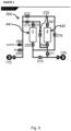
- the coupling valve assembly 200 is configured to, in response to a first control signal 1_DOWN, couple the fluid inlet 110 to the first fluid port 131 and to couple the second fluid port 132 to the fluid outlet 120.
- the valve unit 100 may in one or more embodiments operate in a single column upward flow mode, further described in relation to Fig. 6A and Fig. 6C .
- the coupling valve assembly 200 is configured to, in response to a sixth control signal 2_DOWN-1_DOWN, couple the fluid inlet 110 to the third fluid port 141, couple the fourth fluid port 142 to the first fluid port 131 and to couple the second fluid port 132 to the fluid outlet 120.
- the valve unit 100 may in one or more embodiments operate in a waste mode, further described in relation to Fig. 9 .
- the coupling valve assembly 200 further comprises a packing fluid port 150 and the coupling valve assembly 200 is configured to couple the fluid inlet 110 to packing fluid port 150 in response to receiving a control signal 1_IP or 2_IP.
- the fluid channels comprised in the body 201 of the coupling valve assembly 200 are formed in a direct shape.
- the fluid channels are formed in a direct shape in the sense that each individual fluid channel is formed with one end terminating at a start point and an opposite end terminating at an end point.
- Each individual fluid channel may further be shaped with a substantially constant area of cross sections along the fluid channel.
- the start point and the end point comprises at least one of the fluid inlet 110, the fluid outlet 120, the first fluid port 131, the second fluid port 132, the third fluid port 141, the fourth fluid port 142, a center port 306 and an side port 307.
- the coupling valve assembly 200 further comprises a first pressure sensor 281 coupled to the fluid inlet 110 and configured for measuring a first pressure of the received fluid and a second pressure sensor 282 coupled to the fluid outlet 120 and configured for measuring a second pressure of the provided fluid.
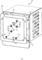
- Fig. 2 shows a section view of the valve unit 100 according to one or more embodiments of the present disclosure.
- the valve unit 100 comprises the fluid inlet 110, the fluid outlet 120, the first fluid port 131 coupled to a side port of a first membrane valve 231, the second fluid port 132 coupled to a side port of a second membrane valve 232, the third fluid port 141 coupled to a side port of a third membrane valve 241 and the fourth fluid port 142 coupled to a side port of a fourth membrane valve 242.
- the valve unit 100 further comprises a fifth membrane valve 271, a sixth membrane valve 272, a seventh membrane valve 273, an eighth membrane valve 274, a ninth membrane valve 275 and a tenth membrane valve 276.
- the valve unit 100 further comprises an eleventh membrane valve 250 and a twelfth membrane valve 260.
- a first fluid channel 291, formed in a direct shape couples the fluid inlet 110 to the seventh membrane valve 273, e.g. to a center port of the seventh membrane valve 273.
- a second fluid channel 292, formed in a direct shape couples the second membrane valve 232, e.g. the side port, to the tenth membrane valve 276, e.g. to the center port.
- a third fluid channel 293, formed in a direct shape couples the second membrane valve 232, e.g. the side port, to the sixth membrane valve 272, e.g. to the center port.
- a fourth fluid channel 294, formed in a direct shape couples the sixth membrane valve 272, e.g. the side port, to the fluid outlet 120.
- a fifth fluid channel 295 formed in a direct shape, couples the eight membrane valve 274, e.g. the side port, to the ninth membrane valve 275, e.g. to the center port.
- the center port of the eight membrane valve 274 is further coupled to the first fluid channel 291.
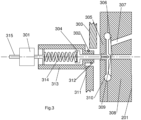
- the membrane valve further comprises a piston 304 arranged along a longitudinal axis 315 and coupled to the membrane 310.
- the membrane valve further comprises a spring 314 arranged along the longitudinal axis 315 and at one end in contact with a piston 304, the spring being urgeable at an opposite end by a drive 301.
- the drive 301 is configured to move the opposite end of the spring 314 along the longitudinal axis 315 in response to a received control signal to obtain said open and closed membrane positions.
- the piston 304 When the membrane 310 reaches the seat 309, the piston 304 is prevented from moving further, but the drive 301 keeps pushing, thereby compressing the spring 314 which gives an increased force on the membrane 310 for closing the valve.
- a position flag close 302 is detected by a position sensor close 303. The stepper motor can then stop, or, if necessary, move a known amount of extra steps to increase the force applied to the membrane 310 even further.
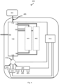
- Fig. 4 shows a chromatography apparatus 400 according to one or more embodiments of the disclosure.
- the chromatography apparatus 400 may typically comprise at least one inlet 455.
- the inlet may optionally be coupled to a reservoir 451 configured to hold a fluid.
- the inlet 455 may e.g. be implemented as tubular elements such as a tube or hose.
- the chromatography apparatus 400 may further comprise the valve unit 100, further described in relation to Fig. 1 .
- the valve unit 100 may be coupled to the reservoir 451 by the inlet 455 coupled to the fluid inlet 110.
- the valve unit 100 may be configured to be coupled to the first column 441 by the first pair of fluid ports 130 and/or configured to be coupled to the second column 442 by the second pair of fluid ports 140.
- the first column 441 and/or the second column 442 may be comprised in the chromatography apparatus 400 or arranged external to the chromatography apparatus 400.
- control unit 410 may further comprise and/or be coupled to one or more additional sensors (not shown in the figure) configured to receive and/or obtain and/or measure physical properties pertaining to the chromatography apparatus 400 and send one or more sensor signals indicative of the physical properties to the processing means 412.
- all membrane valves 231, 232, 241, 242, 250, 260, 271-276 are initially in the closed position.
- a control signal, 1_DOWN is then received, e.g. by circuitry comprised in the coupling valve assembly 200, and a set of the membrane valves are then controlled to the open position.
- the eight membrane valve 274, the first membrane valve 231, the second membrane valve 232 and the sixth membrane valve 272 are then controlled to the open position.
- the first column 441 may then be packed or filled with fluid, e.g. to prepare for an upcoming chromatography run.
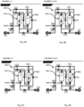
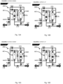
- Fig. 7A schematically shows the coupling valve assembly 200 operating in a dual-column continuous flow mode from the second column 442 to the first column 441 according to one or more embodiments of the present invention.
- Fig. 7A further shows the various membrane valves and fluid channels comprised by the coupling valve assembly 200, further described in relation to Fig. 2 .
- all membrane valves 231, 232, 241, 242, 250, 260, 271-276 are initially in the closed position.
- a control signal, BY_PASS_TOP is then received, e.g. by circuitry comprised in the coupling valve assembly 200, and a set of the membrane valves are then controlled to the open position.
- the seventh membrane valve 273, the tenth membrane valve 276 and the sixth membrane valve 272 are then controlled to the open position.
- the fluid channels providing the top part of the columns with fluid are then filled, rinsed or cleaned, e.g. to prepare the fluid channels for an upcoming chromatography run.
- Fig. 8C schematically shows the coupling valve assembly 200 operating in an all bypass mode according to one or more embodiments of the present invention.
- Fig. 8C further shows the various membrane valves and fluid channels comprised by the coupling valve assembly 200, further described in relation to Fig. 2 .
- Fig. 10A schematically shows the coupling valve assembly 200 first column downward unpacking mode according to one or more embodiments of the present invention.
- Fig. 10A further shows the various membrane valves and fluid channels comprised by the coupling valve assembly 200, further described in relation to Fig. 2 .
- all membrane valves 231, 232, 241, 242, 250, 260, 271-276 are initially in the closed position.
- a control signal, 1_UNPACK_DOWN is then received, e.g. by circuitry comprised in the coupling valve assembly 200, and a set of the membrane valves are then controlled to the open position.
- the eight membrane valve 274 and the first membrane valve 231 are then controlled to the open position.
- Fig. 10C schematically shows the coupling valve assembly 200 second column downward unpacking mode according to one or more embodiments of the present invention.
- Fig. 10C further shows the various membrane valves and fluid channels comprised by the coupling valve assembly 200, further described in relation to Fig. 2 .
- all membrane valves 231, 232, 241, 242, 250, 260, 271-276 are initially in the closed position.
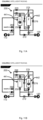
- the eleventh membrane valve 250 is coupled to the first column.
- a control signal, 1_IP is then received, e.g. by circuitry comprised in the coupling valve assembly 200, and a set of the membrane valves are then controlled to the open position.
- the eleventh membrane valve 250, the second membrane valve 232 and the sixth membrane valve 272 are then controlled to the open position.
- the first column 441 may then be packed or filled with fluid, e.g. to prepare for an upcoming chromatography run.
- Fig. 11B schematically shows the coupling valve assembly 200 operating in a packing flow mode or packing flow mode for the second column 442 according to one or more embodiments of the present invention.
- Fig. 11B further shows the various membrane valves and fluid channels comprised by the coupling valve assembly 200, further described in relation to Fig. 2 .
- Flash-OFDM Fast Low-latency Access with Seamless Handoff Orthogonal Frequency Division Multiplexing
- iBurst ® High Capacity Spatial Division Multiple Access
- MBWA Mobile Broadband Wireless Access
- IEEE 802.20 High Performance Radio Metropolitan Area Network
- HIPERMAN High Performance Radio Metropolitan Area Network
- BDMA Beam-Division Multiple Access
- Wi-MAX World Interoperability for Microwave Access
- ultrasonic communication etc., but is not limited thereto.
Landscapes
- Physics & Mathematics (AREA)
- Health & Medical Sciences (AREA)
- Life Sciences & Earth Sciences (AREA)
- Chemical & Material Sciences (AREA)
- Analytical Chemistry (AREA)
- Biochemistry (AREA)
- General Health & Medical Sciences (AREA)
- General Physics & Mathematics (AREA)
- Immunology (AREA)
- Pathology (AREA)
- Engineering & Computer Science (AREA)
- General Engineering & Computer Science (AREA)
- Mechanical Engineering (AREA)
- Treatment Of Liquids With Adsorbents In General (AREA)
Applications Claiming Priority (3)
| Application Number | Priority Date | Filing Date | Title |
|---|---|---|---|
| GBGB1715399.0A GB201715399D0 (en) | 2017-09-22 | 2017-09-22 | Valve unit for a chromatography apparatus |
| PCT/EP2018/075694 WO2019057937A2 (en) | 2017-09-22 | 2018-09-21 | TAP UNIT FOR CHROMATOGRAPHIC APPARATUS |
| EP18779605.7A EP3685155B1 (de) | 2017-09-22 | 2018-09-21 | Ventileinheit für eine chromatographievorrichtung |
Related Parent Applications (2)
| Application Number | Title | Priority Date | Filing Date |
|---|---|---|---|
| EP18779605.7A Division-Into EP3685155B1 (de) | 2017-09-22 | 2018-09-21 | Ventileinheit für eine chromatographievorrichtung |
| EP18779605.7A Division EP3685155B1 (de) | 2017-09-22 | 2018-09-21 | Ventileinheit für eine chromatographievorrichtung |
Publications (2)
| Publication Number | Publication Date |
|---|---|
| EP4534169A2 true EP4534169A2 (de) | 2025-04-09 |
| EP4534169A3 EP4534169A3 (de) | 2025-07-02 |
Family
ID=60244488
Family Applications (2)
| Application Number | Title | Priority Date | Filing Date |
|---|---|---|---|
| EP18779605.7A Active EP3685155B1 (de) | 2017-09-22 | 2018-09-21 | Ventileinheit für eine chromatographievorrichtung |
| EP25159049.3A Pending EP4534169A3 (de) | 2017-09-22 | 2018-09-21 | Ventileinheit für eine chromatographievorrichtung |
Family Applications Before (1)
| Application Number | Title | Priority Date | Filing Date |
|---|---|---|---|
| EP18779605.7A Active EP3685155B1 (de) | 2017-09-22 | 2018-09-21 | Ventileinheit für eine chromatographievorrichtung |
Country Status (6)
| Country | Link |
|---|---|
| US (2) | US11703483B2 (de) |
| EP (2) | EP3685155B1 (de) |
| JP (1) | JP7278268B2 (de) |
| CN (2) | CN120100935A (de) |
| GB (1) | GB201715399D0 (de) |
| WO (1) | WO2019057937A2 (de) |
Families Citing this family (2)
| Publication number | Priority date | Publication date | Assignee | Title |
|---|---|---|---|---|
| GB202105909D0 (en) | 2021-04-26 | 2021-06-09 | Cytiva Sweden Ab | Gb2105909.2 |
| USD1091858S1 (en) * | 2024-01-29 | 2025-09-02 | Inventage Lab Inc. | Lipid nanoparticle preparation device |
Citations (4)
| Publication number | Priority date | Publication date | Assignee | Title |
|---|---|---|---|---|
| US3291726A (en) | 1964-05-04 | 1966-12-13 | Universal Oil Prod Co | Continuous simulated countercurrent sorption process employing desorbent made in said process |
| US3992175A (en) | 1974-02-11 | 1976-11-16 | Toe Jokhannesovich Klementi | Method of and device for chromatographic separation of fluid mixtures into fractions |
| EP1775001A1 (de) | 2005-10-13 | 2007-04-18 | Xendo Holding B.V. | Vorrichtung für chromatographische Trennungen |
| WO2008048395A1 (en) | 2006-08-30 | 2008-04-24 | Semba Biosciences, Inc. | Valve module and methods for simulated moving bed chromatography |
Family Cites Families (36)
| Publication number | Priority date | Publication date | Assignee | Title |
|---|---|---|---|---|
| DE2511269A1 (de) * | 1974-03-15 | 1975-09-25 | Sp K Bjuro Akademii Nauk Eston | Verfahren zur chromatographischen fraktionierung fluider stoffgemische und chromatograph dafuer |
| US5571410A (en) * | 1994-10-19 | 1996-11-05 | Hewlett Packard Company | Fully integrated miniaturized planar liquid sample handling and analysis device |
| JP3502561B2 (ja) * | 1999-02-22 | 2004-03-02 | Smc株式会社 | レギュレーター |
| US6537506B1 (en) * | 2000-02-03 | 2003-03-25 | Cellular Process Chemistry, Inc. | Miniaturized reaction apparatus |
| US6609698B1 (en) * | 2000-10-25 | 2003-08-26 | Arichell Technologies, Inc. | Ferromagnetic/fluid valve actuator |
| US7318912B2 (en) * | 2001-06-07 | 2008-01-15 | Nanostream, Inc. | Microfluidic systems and methods for combining discrete fluid volumes |
| US6848462B2 (en) * | 2001-12-06 | 2005-02-01 | Nanostream, Inc. | Adhesiveless microfluidic device fabrication |
| EP2574400B1 (de) * | 2003-02-05 | 2016-09-28 | Iquum, Inc. | Probenverarbeitung |
| CN101986152B (zh) * | 2005-02-22 | 2012-05-30 | 机械分析公司 | 隔膜密封阀、色谱分析系统及其使用方法 |
| WO2006089389A1 (en) * | 2005-02-22 | 2006-08-31 | Mecanique Analytique Inc. | Diaphragm-sealed valve, analytical chromatographic system and method using the same |
| US7216528B2 (en) * | 2005-02-22 | 2007-05-15 | Mecanique Analytique Inc. | Diaphragm-sealed valve, analytical chromatographic system and method using the same |
| WO2007047498A2 (en) * | 2005-10-14 | 2007-04-26 | The Regents Of The University Of California | Formation and encapsulation of molecular bilayer and monolayer membranes |
| US8920645B2 (en) * | 2005-12-07 | 2014-12-30 | Tarpon Biosystems Inc. | Disposable chromatography valves and system |
| JP3123803U (ja) * | 2006-05-17 | 2006-07-27 | 株式会社島津製作所 | 送液装置 |
| US8807164B2 (en) * | 2006-08-30 | 2014-08-19 | Semba Biosciences, Inc. | Valve module and methods for simulated moving bed chromatography |
| US7790040B2 (en) * | 2006-08-30 | 2010-09-07 | Semba Biosciences, Inc. | Continuous isocratic affinity chromatography |
| US7806137B2 (en) * | 2006-08-30 | 2010-10-05 | Semba Biosciences, Inc. | Control system for simulated moving bed chromatography |
| JP5140721B2 (ja) * | 2007-04-17 | 2013-02-13 | イクスエンド、ホールディング、ベスローテン、フェンノートシャップ | 連続メンブレン吸着方法および装置 |
| EP2160227B1 (de) * | 2007-06-15 | 2019-02-20 | GE Healthcare Bio-Sciences AB | Chromatographieverfahren |
| US8104506B2 (en) * | 2007-07-10 | 2012-01-31 | Mecanique Analytique Inc. | Diaphragm-sealed valve having intermediate communication ports |
| US20090146095A1 (en) * | 2007-12-11 | 2009-06-11 | Marc Baril | Drainable radial diaphragm valve |
| US20090212248A1 (en) * | 2008-02-27 | 2009-08-27 | Eugeniusz Kozak | Solenoid-actuated diaphragm valve |
| US8672532B2 (en) * | 2008-12-31 | 2014-03-18 | Integenx Inc. | Microfluidic methods |
| EP2438154A1 (de) * | 2009-06-02 | 2012-04-11 | Integenx Inc. | Fluidische vorrichtung mit membranventilen |
| BRPI1010169A2 (pt) * | 2009-06-05 | 2016-03-29 | Integenx Inc | sistema que se ajusta dentro de um invólucro de não mais que 10 pés3, cartucho, artigo em forma legível por computador, método, sistema configurado para realizar um método, sistema óptico, instrumento e dispositivo. |
| US8584703B2 (en) * | 2009-12-01 | 2013-11-19 | Integenx Inc. | Device with diaphragm valve |
| JP5226059B2 (ja) * | 2010-11-17 | 2013-07-03 | アドバンス電気工業株式会社 | エア操作弁 |
| WO2013082064A2 (en) * | 2011-11-30 | 2013-06-06 | Corning Incorporated | Method to align covers on structured layers and resulting devices |
| WO2015094094A1 (en) * | 2013-12-19 | 2015-06-25 | Ge Healthcare Bio-Sciences Ab | A chromatography system and method |
| US20140358304A1 (en) * | 2013-06-03 | 2014-12-04 | Tescom Corporation | Method and Apparatus for Managing Fluid Supply in a Process Control System |
| WO2015095658A1 (en) * | 2013-12-19 | 2015-06-25 | Ge Healthcare Bio-Sciences Ab | Remotely actuated valve for a biological liquid treatment system |
| EP3105580B1 (de) * | 2014-02-14 | 2023-10-04 | Cytiva Sweden AB | Mehrstufiges automatisches reinigungssystem |
| CN107106929B (zh) * | 2014-12-31 | 2020-06-09 | 通用电气健康护理生物科学股份公司 | 用于模拟移动床层析的阀歧管 |
| US11357966B2 (en) * | 2015-04-23 | 2022-06-14 | B. Braun Medical Inc. | Compounding device, system, kit, software, and method |
| DE102016108103A1 (de) * | 2016-05-02 | 2016-06-23 | Agilent Technologies, Inc. - A Delaware Corporation - | Kompensation von Volumenartefakten beim Schalten eines Fluidventils |
| DE102017115018A1 (de) * | 2017-07-05 | 2017-09-07 | Agilent Technologies, Inc. - A Delaware Corporation - | Topologiebestimmung im fluidischen Messgerät |
-
2017
- 2017-09-22 GB GBGB1715399.0A patent/GB201715399D0/en not_active Ceased
-
2018
- 2018-09-21 WO PCT/EP2018/075694 patent/WO2019057937A2/en not_active Ceased
- 2018-09-21 JP JP2020516661A patent/JP7278268B2/ja active Active
- 2018-09-21 CN CN202510258898.0A patent/CN120100935A/zh active Pending
- 2018-09-21 CN CN201880075460.7A patent/CN111373255A/zh active Pending
- 2018-09-21 US US16/648,296 patent/US11703483B2/en active Active
- 2018-09-21 EP EP18779605.7A patent/EP3685155B1/de active Active
- 2018-09-21 EP EP25159049.3A patent/EP4534169A3/de active Pending
-
2023
- 2023-05-31 US US18/326,838 patent/US20230304974A1/en active Pending
Patent Citations (4)
| Publication number | Priority date | Publication date | Assignee | Title |
|---|---|---|---|---|
| US3291726A (en) | 1964-05-04 | 1966-12-13 | Universal Oil Prod Co | Continuous simulated countercurrent sorption process employing desorbent made in said process |
| US3992175A (en) | 1974-02-11 | 1976-11-16 | Toe Jokhannesovich Klementi | Method of and device for chromatographic separation of fluid mixtures into fractions |
| EP1775001A1 (de) | 2005-10-13 | 2007-04-18 | Xendo Holding B.V. | Vorrichtung für chromatographische Trennungen |
| WO2008048395A1 (en) | 2006-08-30 | 2008-04-24 | Semba Biosciences, Inc. | Valve module and methods for simulated moving bed chromatography |
Also Published As
| Publication number | Publication date |
|---|---|
| EP3685155B1 (de) | 2025-08-06 |
| JP7278268B2 (ja) | 2023-05-19 |
| CN111373255A (zh) | 2020-07-03 |
| US20200284767A1 (en) | 2020-09-10 |
| JP2020534538A (ja) | 2020-11-26 |
| EP3685155A2 (de) | 2020-07-29 |
| WO2019057937A3 (en) | 2019-05-16 |
| CN120100935A (zh) | 2025-06-06 |
| EP4534169A3 (de) | 2025-07-02 |
| GB201715399D0 (en) | 2017-11-08 |
| US11703483B2 (en) | 2023-07-18 |
| US20230304974A1 (en) | 2023-09-28 |
| EP3685155C0 (de) | 2025-08-06 |
| WO2019057937A2 (en) | 2019-03-28 |
Similar Documents
| Publication | Publication Date | Title |
|---|---|---|
| US20230304974A1 (en) | Valve Unit for a Chromatography Apparatus | |
| US9833754B2 (en) | Sample dilution to specifiable dilution ratio | |
| CN104503931A (zh) | 一种多路模拟信号采集方法 | |
| JP5333941B2 (ja) | 固相抽出装置 | |
| JP2008256654A (ja) | 液体クロマトグラフィ | |
| CN103134889A (zh) | 在线富集-分步聚焦进样-超高效液相色谱联用系统及应用 | |
| US11360056B2 (en) | Interface module for two-dimensional liquid chromatography | |
| EP3638392B1 (de) | Verfahren und vorrichtung zur bestimmung einer oder mehrerer pufferzusammensetzungsrezepte | |
| CN103698445B (zh) | 一种在线的微量样品采集器及采样分析方法 | |
| CN208146014U (zh) | 一种高精度微量移液器 | |
| CN204380318U (zh) | 一种微萃取器 | |
| CN105675775A (zh) | 一种气相色谱快速在线采样、存储与进样的装置及方法 | |
| WO2024012943A1 (en) | Method to configure a system for chemical separation | |
| EP3990912B1 (de) | Chromatographievorrichtung und -verfahren | |
| CN202256276U (zh) | 一种连续流动分析仪和液相色谱仪的连接系统 | |
| KR20250163316A (ko) | 하나 이상의 바이오프로세싱 디바이스에 의해 생성된 소스 데이터를 분석하기 위한 방법 | |
| CN204767602U (zh) | 一种层析柱分离系统 | |
| WO2025157610A1 (en) | Method for prediction of maintenance events in a chromatography apparatus | |
| CN203203827U (zh) | 一种基于步进电机的自动取样系统 | |
| WO2024188685A1 (en) | Method to analyze source data generated by one or more bioprocessing device | |
| WO2025003308A1 (en) | Sampling module for a bioprocess purification system | |
| CN108614172A (zh) | 一种多通讯接口的小型化网络分析仪 | |
| EP4519670A1 (de) | Verfahren und vorrichtung zur chromatographischen trennung | |
| CN206594123U (zh) | 一种液相色谱仪的监测器切换器 | |
| CN103207099A (zh) | 一种基于步进电机的自动取样系统 |
Legal Events
| Date | Code | Title | Description |
|---|---|---|---|
| PUAI | Public reference made under article 153(3) epc to a published international application that has entered the european phase |
Free format text: ORIGINAL CODE: 0009012 |
|
| STAA | Information on the status of an ep patent application or granted ep patent |
Free format text: STATUS: REQUEST FOR EXAMINATION WAS MADE |
|
| 17P | Request for examination filed |
Effective date: 20250306 |
|
| AC | Divisional application: reference to earlier application |
Ref document number: 3685155 Country of ref document: EP Kind code of ref document: P |
|
| AK | Designated contracting states |
Kind code of ref document: A2 Designated state(s): AL AT BE BG CH CY CZ DE DK EE ES FI FR GB GR HR HU IE IS IT LI LT LU LV MC MK MT NL NO PL PT RO RS SE SI SK SM TR |
|
| REG | Reference to a national code |
Ref country code: DE Ref legal event code: R079 Free format text: PREVIOUS MAIN CLASS: B01D0015180000 Ipc: G01N0030420000 |
|
| PUAL | Search report despatched |
Free format text: ORIGINAL CODE: 0009013 |
|
| STAA | Information on the status of an ep patent application or granted ep patent |
Free format text: STATUS: EXAMINATION IS IN PROGRESS |
|
| AK | Designated contracting states |
Kind code of ref document: A3 Designated state(s): AL AT BE BG CH CY CZ DE DK EE ES FI FR GB GR HR HU IE IS IT LI LT LU LV MC MK MT NL NO PL PT RO RS SE SI SK SM TR |
|
| RIC1 | Information provided on ipc code assigned before grant |
Ipc: G01N 30/20 20060101ALN20250527BHEP Ipc: G01N 30/46 20060101ALN20250527BHEP Ipc: G01N 30/38 20060101ALI20250527BHEP Ipc: B01D 15/18 20060101ALI20250527BHEP Ipc: G01N 30/42 20060101AFI20250527BHEP |
|
| 17Q | First examination report despatched |
Effective date: 20250613 |