EP4531270A1 - Motorsteuerung, antriebsstrang und elektrofahrzeug - Google Patents
Motorsteuerung, antriebsstrang und elektrofahrzeug Download PDFInfo
- Publication number
- EP4531270A1 EP4531270A1 EP23867080.6A EP23867080A EP4531270A1 EP 4531270 A1 EP4531270 A1 EP 4531270A1 EP 23867080 A EP23867080 A EP 23867080A EP 4531270 A1 EP4531270 A1 EP 4531270A1
- Authority
- EP
- European Patent Office
- Prior art keywords
- control unit
- switching transistors
- bridge switching
- motor control
- conduction mode
- Prior art date
- Legal status (The legal status is an assumption and is not a legal conclusion. Google has not performed a legal analysis and makes no representation as to the accuracy of the status listed.)
- Pending
Links
Images


Classifications
-
- H—ELECTRICITY
- H02—GENERATION; CONVERSION OR DISTRIBUTION OF ELECTRIC POWER
- H02P—CONTROL OR REGULATION OF ELECTRIC MOTORS, ELECTRIC GENERATORS OR DYNAMO-ELECTRIC CONVERTERS; CONTROLLING TRANSFORMERS, REACTORS OR CHOKE COILS
- H02P29/00—Arrangements for regulating or controlling electric motors, appropriate for both AC and DC motors
- H02P29/02—Providing protection against overload without automatic interruption of supply
- H02P29/024—Detecting a fault condition, e.g. short circuit, locked rotor, open circuit or loss of load
- H02P29/0241—Detecting a fault condition, e.g. short circuit, locked rotor, open circuit or loss of load the fault being an overvoltage
-
- H—ELECTRICITY
- H02—GENERATION; CONVERSION OR DISTRIBUTION OF ELECTRIC POWER
- H02P—CONTROL OR REGULATION OF ELECTRIC MOTORS, ELECTRIC GENERATORS OR DYNAMO-ELECTRIC CONVERTERS; CONTROLLING TRANSFORMERS, REACTORS OR CHOKE COILS
- H02P27/00—Arrangements or methods for the control of AC motors characterised by the kind of supply voltage
- H02P27/04—Arrangements or methods for the control of AC motors characterised by the kind of supply voltage using variable-frequency supply voltage, e.g. inverter or converter supply voltage
- H02P27/06—Arrangements or methods for the control of AC motors characterised by the kind of supply voltage using variable-frequency supply voltage, e.g. inverter or converter supply voltage using DC to AC converters or inverters
- H02P27/08—Arrangements or methods for the control of AC motors characterised by the kind of supply voltage using variable-frequency supply voltage, e.g. inverter or converter supply voltage using DC to AC converters or inverters with pulse width modulation
-
- B—PERFORMING OPERATIONS; TRANSPORTING
- B60—VEHICLES IN GENERAL
- B60L—PROPULSION OF ELECTRICALLY-PROPELLED VEHICLES; SUPPLYING ELECTRIC POWER FOR AUXILIARY EQUIPMENT OF ELECTRICALLY-PROPELLED VEHICLES; ELECTRODYNAMIC BRAKE SYSTEMS FOR VEHICLES IN GENERAL; MAGNETIC SUSPENSION OR LEVITATION FOR VEHICLES; MONITORING OPERATING VARIABLES OF ELECTRICALLY-PROPELLED VEHICLES; ELECTRIC SAFETY DEVICES FOR ELECTRICALLY-PROPELLED VEHICLES
- B60L15/00—Methods, circuits, or devices for controlling the traction-motor speed of electrically-propelled vehicles
- B60L15/007—Physical arrangements or structures of drive train converters specially adapted for the propulsion motors of electric vehicles
-
- B—PERFORMING OPERATIONS; TRANSPORTING
- B60—VEHICLES IN GENERAL
- B60L—PROPULSION OF ELECTRICALLY-PROPELLED VEHICLES; SUPPLYING ELECTRIC POWER FOR AUXILIARY EQUIPMENT OF ELECTRICALLY-PROPELLED VEHICLES; ELECTRODYNAMIC BRAKE SYSTEMS FOR VEHICLES IN GENERAL; MAGNETIC SUSPENSION OR LEVITATION FOR VEHICLES; MONITORING OPERATING VARIABLES OF ELECTRICALLY-PROPELLED VEHICLES; ELECTRIC SAFETY DEVICES FOR ELECTRICALLY-PROPELLED VEHICLES
- B60L15/00—Methods, circuits, or devices for controlling the traction-motor speed of electrically-propelled vehicles
- B60L15/02—Methods, circuits, or devices for controlling the traction-motor speed of electrically-propelled vehicles characterised by the form of the current used in the control circuit
- B60L15/06—Methods, circuits, or devices for controlling the traction-motor speed of electrically-propelled vehicles characterised by the form of the current used in the control circuit using substantially sinusoidal AC
-
- B—PERFORMING OPERATIONS; TRANSPORTING
- B60—VEHICLES IN GENERAL
- B60L—PROPULSION OF ELECTRICALLY-PROPELLED VEHICLES; SUPPLYING ELECTRIC POWER FOR AUXILIARY EQUIPMENT OF ELECTRICALLY-PROPELLED VEHICLES; ELECTRODYNAMIC BRAKE SYSTEMS FOR VEHICLES IN GENERAL; MAGNETIC SUSPENSION OR LEVITATION FOR VEHICLES; MONITORING OPERATING VARIABLES OF ELECTRICALLY-PROPELLED VEHICLES; ELECTRIC SAFETY DEVICES FOR ELECTRICALLY-PROPELLED VEHICLES
- B60L15/00—Methods, circuits, or devices for controlling the traction-motor speed of electrically-propelled vehicles
- B60L15/20—Methods, circuits, or devices for controlling the traction-motor speed of electrically-propelled vehicles for control of the vehicle or its driving motor to achieve a desired performance, e.g. speed, torque, programmed variation of speed
-
- H—ELECTRICITY
- H02—GENERATION; CONVERSION OR DISTRIBUTION OF ELECTRIC POWER
- H02M—APPARATUS FOR CONVERSION BETWEEN AC AND AC, BETWEEN AC AND DC, OR BETWEEN DC AND DC, AND FOR USE WITH MAINS OR SIMILAR POWER SUPPLY SYSTEMS; CONVERSION OF DC OR AC INPUT POWER INTO SURGE OUTPUT POWER; CONTROL OR REGULATION THEREOF
- H02M1/00—Details of apparatus for conversion
- H02M1/0003—Details of control, feedback or regulation circuits
- H02M1/0009—Devices or circuits for detecting current in a converter
-
- H—ELECTRICITY
- H02—GENERATION; CONVERSION OR DISTRIBUTION OF ELECTRIC POWER
- H02M—APPARATUS FOR CONVERSION BETWEEN AC AND AC, BETWEEN AC AND DC, OR BETWEEN DC AND DC, AND FOR USE WITH MAINS OR SIMILAR POWER SUPPLY SYSTEMS; CONVERSION OF DC OR AC INPUT POWER INTO SURGE OUTPUT POWER; CONTROL OR REGULATION THEREOF
- H02M1/00—Details of apparatus for conversion
- H02M1/32—Means for protecting converters other than automatic disconnection
-
- H—ELECTRICITY
- H02—GENERATION; CONVERSION OR DISTRIBUTION OF ELECTRIC POWER
- H02M—APPARATUS FOR CONVERSION BETWEEN AC AND AC, BETWEEN AC AND DC, OR BETWEEN DC AND DC, AND FOR USE WITH MAINS OR SIMILAR POWER SUPPLY SYSTEMS; CONVERSION OF DC OR AC INPUT POWER INTO SURGE OUTPUT POWER; CONTROL OR REGULATION THEREOF
- H02M7/00—Conversion of AC power input into DC power output; Conversion of DC power input into AC power output
- H02M7/42—Conversion of DC power input into AC power output without possibility of reversal
- H02M7/44—Conversion of DC power input into AC power output without possibility of reversal by static converters
- H02M7/48—Conversion of DC power input into AC power output without possibility of reversal by static converters using discharge tubes with control electrode or semiconductor devices with control electrode
- H02M7/53—Conversion of DC power input into AC power output without possibility of reversal by static converters using discharge tubes with control electrode or semiconductor devices with control electrode using devices of a triode or transistor type requiring continuous application of a control signal
- H02M7/537—Conversion of DC power input into AC power output without possibility of reversal by static converters using discharge tubes with control electrode or semiconductor devices with control electrode using devices of a triode or transistor type requiring continuous application of a control signal using semiconductor devices only, e.g. single switched pulse inverters
- H02M7/5387—Conversion of DC power input into AC power output without possibility of reversal by static converters using discharge tubes with control electrode or semiconductor devices with control electrode using devices of a triode or transistor type requiring continuous application of a control signal using semiconductor devices only, e.g. single switched pulse inverters in a bridge configuration
- H02M7/53871—Conversion of DC power input into AC power output without possibility of reversal by static converters using discharge tubes with control electrode or semiconductor devices with control electrode using devices of a triode or transistor type requiring continuous application of a control signal using semiconductor devices only, e.g. single switched pulse inverters in a bridge configuration with automatic control of output voltage or current
-
- H—ELECTRICITY
- H02—GENERATION; CONVERSION OR DISTRIBUTION OF ELECTRIC POWER
- H02P—CONTROL OR REGULATION OF ELECTRIC MOTORS, ELECTRIC GENERATORS OR DYNAMO-ELECTRIC CONVERTERS; CONTROLLING TRANSFORMERS, REACTORS OR CHOKE COILS
- H02P23/00—Arrangements or methods for the control of AC motors characterised by a control method other than vector control
- H02P23/0004—Control strategies in general, e.g. linear type, e.g. P, PI, PID, using robust control
- H02P23/0027—Control strategies in general, e.g. linear type, e.g. P, PI, PID, using robust control using different modes of control depending on a parameter, e.g. the speed
-
- H—ELECTRICITY
- H02—GENERATION; CONVERSION OR DISTRIBUTION OF ELECTRIC POWER
- H02P—CONTROL OR REGULATION OF ELECTRIC MOTORS, ELECTRIC GENERATORS OR DYNAMO-ELECTRIC CONVERTERS; CONTROLLING TRANSFORMERS, REACTORS OR CHOKE COILS
- H02P23/00—Arrangements or methods for the control of AC motors characterised by a control method other than vector control
- H02P23/14—Estimation or adaptation of motor parameters, e.g. rotor time constant, flux, speed, current or voltage
-
- H—ELECTRICITY
- H02—GENERATION; CONVERSION OR DISTRIBUTION OF ELECTRIC POWER
- H02P—CONTROL OR REGULATION OF ELECTRIC MOTORS, ELECTRIC GENERATORS OR DYNAMO-ELECTRIC CONVERTERS; CONTROLLING TRANSFORMERS, REACTORS OR CHOKE COILS
- H02P3/00—Arrangements for stopping or slowing electric motors, generators, or dynamo-electric converters
- H02P3/06—Arrangements for stopping or slowing electric motors, generators, or dynamo-electric converters for stopping or slowing an individual dynamo-electric motor or dynamo-electric converter
- H02P3/18—Arrangements for stopping or slowing electric motors, generators, or dynamo-electric converters for stopping or slowing an individual dynamo-electric motor or dynamo-electric converter for stopping or slowing an AC motor
- H02P3/22—Arrangements for stopping or slowing electric motors, generators, or dynamo-electric converters for stopping or slowing an individual dynamo-electric motor or dynamo-electric converter for stopping or slowing an AC motor by short-circuit or resistive braking
-
- B—PERFORMING OPERATIONS; TRANSPORTING
- B60—VEHICLES IN GENERAL
- B60L—PROPULSION OF ELECTRICALLY-PROPELLED VEHICLES; SUPPLYING ELECTRIC POWER FOR AUXILIARY EQUIPMENT OF ELECTRICALLY-PROPELLED VEHICLES; ELECTRODYNAMIC BRAKE SYSTEMS FOR VEHICLES IN GENERAL; MAGNETIC SUSPENSION OR LEVITATION FOR VEHICLES; MONITORING OPERATING VARIABLES OF ELECTRICALLY-PROPELLED VEHICLES; ELECTRIC SAFETY DEVICES FOR ELECTRICALLY-PROPELLED VEHICLES
- B60L2240/00—Control parameters of input or output; Target parameters
- B60L2240/40—Drive Train control parameters
- B60L2240/42—Drive Train control parameters related to electric machines
- B60L2240/421—Speed
-
- B—PERFORMING OPERATIONS; TRANSPORTING
- B60—VEHICLES IN GENERAL
- B60L—PROPULSION OF ELECTRICALLY-PROPELLED VEHICLES; SUPPLYING ELECTRIC POWER FOR AUXILIARY EQUIPMENT OF ELECTRICALLY-PROPELLED VEHICLES; ELECTRODYNAMIC BRAKE SYSTEMS FOR VEHICLES IN GENERAL; MAGNETIC SUSPENSION OR LEVITATION FOR VEHICLES; MONITORING OPERATING VARIABLES OF ELECTRICALLY-PROPELLED VEHICLES; ELECTRIC SAFETY DEVICES FOR ELECTRICALLY-PROPELLED VEHICLES
- B60L2240/00—Control parameters of input or output; Target parameters
- B60L2240/40—Drive Train control parameters
- B60L2240/42—Drive Train control parameters related to electric machines
- B60L2240/423—Torque
-
- B—PERFORMING OPERATIONS; TRANSPORTING
- B60—VEHICLES IN GENERAL
- B60L—PROPULSION OF ELECTRICALLY-PROPELLED VEHICLES; SUPPLYING ELECTRIC POWER FOR AUXILIARY EQUIPMENT OF ELECTRICALLY-PROPELLED VEHICLES; ELECTRODYNAMIC BRAKE SYSTEMS FOR VEHICLES IN GENERAL; MAGNETIC SUSPENSION OR LEVITATION FOR VEHICLES; MONITORING OPERATING VARIABLES OF ELECTRICALLY-PROPELLED VEHICLES; ELECTRIC SAFETY DEVICES FOR ELECTRICALLY-PROPELLED VEHICLES
- B60L2240/00—Control parameters of input or output; Target parameters
- B60L2240/40—Drive Train control parameters
- B60L2240/42—Drive Train control parameters related to electric machines
- B60L2240/427—Voltage
-
- B—PERFORMING OPERATIONS; TRANSPORTING
- B60—VEHICLES IN GENERAL
- B60L—PROPULSION OF ELECTRICALLY-PROPELLED VEHICLES; SUPPLYING ELECTRIC POWER FOR AUXILIARY EQUIPMENT OF ELECTRICALLY-PROPELLED VEHICLES; ELECTRODYNAMIC BRAKE SYSTEMS FOR VEHICLES IN GENERAL; MAGNETIC SUSPENSION OR LEVITATION FOR VEHICLES; MONITORING OPERATING VARIABLES OF ELECTRICALLY-PROPELLED VEHICLES; ELECTRIC SAFETY DEVICES FOR ELECTRICALLY-PROPELLED VEHICLES
- B60L2240/00—Control parameters of input or output; Target parameters
- B60L2240/40—Drive Train control parameters
- B60L2240/42—Drive Train control parameters related to electric machines
- B60L2240/429—Current
-
- B—PERFORMING OPERATIONS; TRANSPORTING
- B60—VEHICLES IN GENERAL
- B60L—PROPULSION OF ELECTRICALLY-PROPELLED VEHICLES; SUPPLYING ELECTRIC POWER FOR AUXILIARY EQUIPMENT OF ELECTRICALLY-PROPELLED VEHICLES; ELECTRODYNAMIC BRAKE SYSTEMS FOR VEHICLES IN GENERAL; MAGNETIC SUSPENSION OR LEVITATION FOR VEHICLES; MONITORING OPERATING VARIABLES OF ELECTRICALLY-PROPELLED VEHICLES; ELECTRIC SAFETY DEVICES FOR ELECTRICALLY-PROPELLED VEHICLES
- B60L2240/00—Control parameters of input or output; Target parameters
- B60L2240/40—Drive Train control parameters
- B60L2240/52—Drive Train control parameters related to converters
- B60L2240/526—Operating parameters
-
- B—PERFORMING OPERATIONS; TRANSPORTING
- B60—VEHICLES IN GENERAL
- B60L—PROPULSION OF ELECTRICALLY-PROPELLED VEHICLES; SUPPLYING ELECTRIC POWER FOR AUXILIARY EQUIPMENT OF ELECTRICALLY-PROPELLED VEHICLES; ELECTRODYNAMIC BRAKE SYSTEMS FOR VEHICLES IN GENERAL; MAGNETIC SUSPENSION OR LEVITATION FOR VEHICLES; MONITORING OPERATING VARIABLES OF ELECTRICALLY-PROPELLED VEHICLES; ELECTRIC SAFETY DEVICES FOR ELECTRICALLY-PROPELLED VEHICLES
- B60L2240/00—Control parameters of input or output; Target parameters
- B60L2240/40—Drive Train control parameters
- B60L2240/52—Drive Train control parameters related to converters
- B60L2240/529—Current
-
- Y—GENERAL TAGGING OF NEW TECHNOLOGICAL DEVELOPMENTS; GENERAL TAGGING OF CROSS-SECTIONAL TECHNOLOGIES SPANNING OVER SEVERAL SECTIONS OF THE IPC; TECHNICAL SUBJECTS COVERED BY FORMER USPC CROSS-REFERENCE ART COLLECTIONS [XRACs] AND DIGESTS
- Y02—TECHNOLOGIES OR APPLICATIONS FOR MITIGATION OR ADAPTATION AGAINST CLIMATE CHANGE
- Y02T—CLIMATE CHANGE MITIGATION TECHNOLOGIES RELATED TO TRANSPORTATION
- Y02T10/00—Road transport of goods or passengers
- Y02T10/60—Other road transportation technologies with climate change mitigation effect
- Y02T10/64—Electric machine technologies in electromobility
Definitions
- Embodiments of this application relate to the field of electronic circuit technologies, and in particular, to a motor control unit, a powertrain, and an electric vehicle.
- a motor control unit (motor control unit, MCU) can still be controlled to enter a safety state.
- the safety state may be an active short circuit (active short circuit, ASC) state, or may be a safety pulse off (safety pulse off, SPO) state. Therefore, it is very important to accurately control the motor control unit when the processor-level fault occurs in the electric vehicle.
- Embodiments of this application disclose a motor control unit, a powertrain, and an electric vehicle, to improve control accuracy of the motor control unit.
- this application discloses a motor control unit, configured to control a drive motor of an electric vehicle, where the drive motor includes three phase windings, the motor control unit includes an inverter circuit, the inverter circuit supplies power to the drive motor, the inverter circuit includes three bridge arms, each bridge arm includes an upper bridge switching transistor and a lower bridge switching transistor, and bridge arm midpoints of the three bridge arms are respectively connected to the three phase windings of the drive motor, where in response to a current frequency of at least one phase winding in the three phase windings being greater than or equal to a first frequency threshold, operating modes of three upper bridge switching transistors are switched from an alternate conduction mode to a continuous conduction mode, and operating modes of three lower bridge switching transistors are switched from an alternate conduction mode to a continuous cutoff mode; or operating modes of three upper bridge switching transistors are switched from an alternate conduction mode to a continuous cutoff mode, and operating modes of three lower bridge switching transistors are switched from an alternate conduction mode to a continuous conduction mode; or operating modes of three upper bridge switching
- the operating modes of the three upper bridge switching transistors in the inverter circuit may be switched from an alternate conduction mode to a continuous conduction mode, and the operating modes of the three lower bridge switching transistors may be switched from an alternate conduction mode to a continuous cutoff mode; or the operating modes of the three upper bridge switching transistors may be switched from an alternate conduction mode to a continuous cutoff mode, and the operating modes of the three lower bridge switching transistors may be switched from an alternate conduction mode to a continuous conduction mode; or the operating modes of the three upper bridge switching transistors and the three lower bridge switching transistors in the inverter circuit may be switched from an alternate conduction mode to a continuous cutoff mode.
- the operating modes of the three upper bridge switching transistors and the three lower bridge switching transistors in the inverter circuit may be switched from an alternate conduction mode to a continuous cutoff mode; or the operating modes of the three upper bridge switching transistors or the three lower bridge switching transistors in the inverter circuit may be switched from a continuous conduction mode to a continuous cutoff mode.
- operating states of the six switching transistors in the inverter circuit are determined based on the current frequency of the at least one phase winding in the three phase windings, instead of being determined based on a back electromotive force frequency of the winding. Because an amplitude of a current signal is higher than an amplitude of a voltage signal, anti-interference capability is strong. Therefore, when the processor-level fault occurs in the electric vehicle, the operating states of the six switching transistors in the inverter circuit are accurately determined based on the current frequency of the at least one phase winding in the three phase windings. This can improve control accuracy of the motor control unit.
- the motor control unit includes a current detection circuit, and the current detection circuit is configured to: detect a current frequency of at least one phase winding in the three phase windings; and in response to a current frequency of at least one phase winding in the three phase windings being greater than or equal to the first frequency threshold, output a first detection signal indicating that the rotational speed of the drive motor is greater than or equal to a first threshold; or in response to a current frequency of at least one phase winding in the three phase windings being less than the second frequency threshold, output a second detection signal indicating that the rotational speed of the drive motor is less than or equal to a second threshold.
- the first threshold is greater than the second threshold.
- the current detection circuit in the motor control unit can accurately detect the current signal flowing through the at least one phase winding in the three phase windings of the drive motor. Because the amplitude of the current signal is higher than the amplitude of the voltage signal, and the anti-interference capability is strong, the operating states of the six switching transistors in the inverter circuit can be accurately determined based on the current frequency of the at least one phase winding in the three phase windings, thereby improving the control accuracy of the motor control unit.
- the motor control unit includes a control module, and the control module is configured to: control a running mode of the motor control unit; and in response to the first detection signal, output a first control signal for controlling the motor control unit to run in an active short circuit state or a second control signal for controlling the motor control unit to run in a safety pulse off state; or in response to the second detection signal, output the second control signal for controlling the motor control unit to run in a safety pulse off state.
- the operating modes of the three upper bridge switching transistors are a continuous conduction mode, and the operating modes of the three lower bridge switching transistors are a continuous cutoff mode; or the operating modes of the three upper bridge switching transistors are a continuous cutoff mode, and the operating modes of the three lower bridge switching transistors are a continuous conduction mode.
- the operating modes of the three upper bridge switching transistors and the three lower bridge switching transistors are all a continuous cutoff mode.
- the motor control unit includes a control module, and the control module is configured to: control a running mode of the motor control unit; and in response to a current frequency of at least one phase winding in the three phase windings being greater than or equal to the first frequency threshold, control the motor control unit to run in an active short circuit state or a safety pulse off state; or in response to a current frequency of at least one phase winding in the three phase windings being less than or equal to the second frequency threshold, control the motor control unit to run in a safety pulse off state.
- the motor control unit includes a drive circuit, and the drive circuit is configured to: control running modes of the upper bridge switching transistors and the lower bridge switching transistors in the inverter circuit; and in response to the first control signal, control the operating modes of the three upper bridge switching transistors to switch from an alternate conduction mode to a continuous conduction mode and the operating modes of the three lower bridge switching transistors to switch from an alternate conduction mode to a continuous cutoff mode; or control the operating modes of the three upper bridge switching transistors to switch from an alternate conduction mode to a continuous cutoff mode and the operating modes of the three lower bridge switching transistors to switch from an alternate conduction mode to a continuous conduction mode; or in response to the second control signal, control the operating modes of the three upper bridge switching transistors and the three lower bridge switching transistors to switch from an alternate conduction mode to a continuous cutoff mode; or control the operating modes of the three upper bridge switching transistors or the three lower bridge switching transistors to switch from a continuous conduction mode to a continuous cutoff mode.
- the motor control unit includes a drive circuit, and the drive circuit is configured to: control running modes of the upper bridge switching transistors and the lower bridge switching transistors in the inverter circuit; and in response to a current frequency of at least one phase winding in the three phase windings being greater than or equal to the first frequency threshold, control the operating modes of the three upper bridge switching transistors to switch from an alternate conduction mode to a continuous conduction mode and the operating modes of the three lower bridge switching transistors to switch from an alternate conduction mode to a continuous cutoff mode; or control the operating modes of the three upper bridge switching transistors to switch from an alternate conduction mode to a continuous cutoff mode and the operating modes of the three lower bridge switching transistors to switch from an alternate conduction mode to a continuous conduction mode; or control the operating modes of the three upper bridge switching transistors and the three lower bridge switching transistors to switch from an alternate conduction mode to a continuous cutoff mode; or in response to a current frequency of at least one phase winding in the three phase windings being less than the
- control module and/or the drive circuit are/is configured to receive power supplied by two or more independent power supplies.
- control module and/or the drive circuit are/is powered by two or more independent power supplies.
- another power supply may supply power, to ensure normal power supply to the control module and/or the drive circuit. This can improve safety.
- the first frequency threshold and the second frequency threshold are adjusted with an input voltage of the inverter circuit.
- the first frequency threshold and the second frequency threshold can be adjusted with the input voltage of the inverter circuit, and the current frequency in the ASC state and the SPO state can also vary with a change of the input voltage of the inverter circuit. This can improve adaptability of the motor control unit.
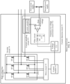
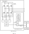
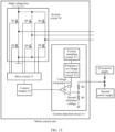
- the current detection circuit includes a current sampling circuit, a frequency-to-voltage conversion circuit, and a voltage comparator.
- the current sampling circuit is configured to output an alternating current signal based on a current frequency of at least one phase winding in the three phase windings;
- the frequency-to-voltage conversion circuit is configured to output a direct current signal based on a result of comparison between a voltage of the alternating current signal and a first reference voltage;
- the voltage comparator is configured to output the first detection signal or the second detection signal based on a result of comparison between a voltage of the direct current signal and a second reference voltage.
- the current sampling circuit includes one or more Hall effect sensors, and there is a spacing between each Hall effect sensor and any electrical connection line between the bridge arm midpoints of the three bridge arms and the three phase windings of the drive motor.
- the alternating current signal is detected by a current sampler, and the current sampler is located on a low-voltage side, isolation and packaging do not need to be performed in consideration of safety regulations, and a smaller board area is occupied.
- the frequency-to-voltage conversion circuit includes a comparator and a filter circuit.
- a first input end of the comparator is connected to the current sampling circuit, a second input end of the comparator is connected to the first reference voltage, and the filter circuit is separately connected to an output end of the comparator and the voltage comparator.
- the current sampling circuit detects the current signal flowing through the at least one phase winding in the three phase windings of the drive motor. An amplitude of the current signal is higher.
- the frequency-to-voltage conversion circuit can implement conversion from a frequency signal to a voltage signal by using a simple circuit. The circuit structure is simple, costs are low, and reliability is higher.
- a first input end of the voltage comparator is connected to the second reference voltage
- a second input end of the voltage comparator is connected to the frequency-to-voltage conversion circuit
- an output end of the voltage comparator is connected to the control module.
- the second reference voltage is adjusted with the input voltage of the inverter circuit.
- the reference voltage of the voltage comparator can be adjusted with the input voltage of the inverter circuit, and the current frequency in the ASC state and the SPO state can also vary with a change of a voltage of a high-voltage bus. This can improve adaptability of the motor control unit.
- this application discloses a powertrain, where the powertrain includes a drive motor configured to control an electric vehicle and the motor control unit disclosed in any one of the first aspect or the possible implementations of the first aspect, and the motor control unit supplies power to the drive motor.
- this application discloses an electric vehicle, including a power battery and the motor control unit disclosed in any one of the first aspect or the possible implementations of the first aspect or the powertrain disclosed in any one of the second aspect or the possible implementations of the second aspect.
- the power battery supplies power to the motor control unit or the powertrain.
- Embodiments of this application disclose a motor control unit, a powertrain, and an electric vehicle, to improve control accuracy of the motor control unit. Details are separately described below.
- At least one (item) indicates one or more and "a plurality of” indicates two or more.
- the term “and/or” is used for describing an association relationship between associated objects, and represents that three relationships may exist.
- a and/or B may represent the following three cases: Only A exists, only B exists, and both A and B exist, where A and B may be singular or plural.
- the character “/” generally indicates an "or” relationship between the associated objects.
- At least one of the following items (pieces) or a similar expression thereof indicates any combination of these items, including a single item (piece) or any combination of a plurality of items (pieces).
- At least one item (piece) of a, b, or c may indicate: a, b, c, a and b, a and c, b and c, or a, b, and c, where a, b, and c may be singular or plural.
- Coupled and “connection” indicates an electrical connection, including direct connection through a wire or a connection end, or indirect connection by using another component (for example, an inductor, a capacitor, or a resistor in embodiments of this application). Therefore, “coupling” and “connection” should be considered as a generalized electronic communication connection.
- the displayed or discussed mutual couplings or direct couplings or connections may be implemented through some interfaces.
- the indirect couplings or connections between the apparatuses, units, or devices may be implemented in communication, electrical, or other forms.
- circuits or other components may be described as or referred to as “configured to” perform one or more tasks.
- the term “configured to” is used for implying a structure by indicating that a circuit/component includes a structure (for example, a circuit system) that performs one or more tasks during operation. Therefore, even when a specified circuit/component is currently not operable (for example, not opened), the circuit/component may also be referred to as being configured to perform the task.
- Circuits/components used in conjunction with the "configured to” phrase include hardware, for example, a circuit for performing an operation.
- a component may be, but is not limited to, a process that runs on a processor, a processor, an object, an executable file, an execution thread, a program, and/or a computer.
- an application that runs on a computing device and the computing device may be components.
- One or more components may reside within a process and/or an execution thread, and a component may be located on one computer and/or distributed between two or more computers.
- these components may be executed from various computer-readable media that store various data structures.
- the components may communicate by using a local and/or remote process and based on, for example, a signal having one or more data packets (for example, data from two components interacting with another component in a local system, a distributed system, and/or across a network such as an internet interacting with other systems by using the signal).
- a signal having one or more data packets (for example, data from two components interacting with another component in a local system, a distributed system, and/or across a network such as an internet interacting with other systems by using the signal).
- FIG. 1 is a diagram of a scenario of an electric vehicle according to an embodiment of this application.
- the electric vehicle may include a power battery 101 and a powertrain 102.
- the power battery 101 is connected to the powertrain 102.
- the power battery 101 may supply power to the powertrain 102.
- the power supply may charge the power battery 101 through the powertrain 102.
- FIG. 2 is a diagram of a structure of a powertrain according to an embodiment of this application.
- a powertrain 102 may include a drive motor 202 and a motor control unit 201.
- the motor control unit 201 is configured to control a running status of the drive motor 202. Specifically, the motor control unit 201 outputs three phase currents to supply power to three phase windings of the drive motor 202.
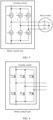
- FIG. 3 is a diagram of a structure of another powertrain according to an embodiment of this application.
- a motor control unit 201 includes an inverter circuit.
- the inverter circuit includes three bridge arms, and a drive motor may include three phase windings.
- Each of the three bridge arms includes an upper bridge switching transistor and a lower bridge switching transistor, and bridge arm midpoints of the three bridge arms are respectively connected to the three phase windings of the drive motor.
- the bridge arm midpoints of the three bridge arms respectively output three phase currents to supply power to the three phase windings of the drive motor 202.
- the inverter circuit includes a bridge arm 1, a bridge arm 2, and a bridge arm 3.
- the bridge arm 1 of the inverter circuit may include a switching transistor Q1 and a switching transistor Q2
- the bridge arm 2 of the inverter circuit may include a switching transistor Q3 and a switching transistor Q4
- the bridge arm 3 of the inverter circuit may include a switching transistor Q5 and a switching transistor Q6.
- a midpoint of the bridge arm 1 of the inverter circuit is connected to a winding 1 of the drive motor, and outputs a phase current to the winding 1 of the drive motor.
- a midpoint of the bridge arm 2 of the inverter circuit is connected to a winding 2 of the drive motor, and outputs a phase current to the winding 2 of the drive motor.
- a midpoint of the bridge arm 3 of the inverter circuit is connected to a winding 3 of the drive motor, and outputs a phase current to the winding 3 of the drive motor.
- the switching transistor may be a metal-oxide semiconductor field-effect transistor (metal-oxide semiconductor field-effect transistor, MOSFET), or may be an insulated gate bipolar transistor (insulated gate bipolar transistor, IGBT), or may be a gallium nitride (gallium nitride, GaN) switching transistor, or may be a silicon carbide (silicon carbide, SiC) switching transistor.
- MOSFET metal-oxide semiconductor field-effect transistor
- IGBT insulated gate bipolar transistor
- gallium nitride gallium nitride
- GaN gallium nitride
- SiC silicon carbide
- a rotational speed of a drive motor may be excessively high or excessively low, and the electric vehicle is prone to a traffic accident.
- the processor-level fault occurs in the motor control unit, it may be understood that a component such as a DSP in the motor control unit is faulty or a power supply fault occurs on a component such as a DSP.
- the motor control unit cannot control, according to an instruction of the DSP, the rotational speed of the drive motor.
- a rotational speed of a drive motor is usually detected by measuring a back electromotive force of a winding of the drive motor. Specifically, voltage signals of two phase windings in the three phase windings of the drive motor are detected, and the two voltage signals are compared to obtain a back electromotive force signal.
- anti-interference capability of the signal obtained through back electromotive force detection of the drive motor is weak. Consequently, the motor control unit cannot be accurately controlled, and it is difficult to ensure safety of the electric vehicle.
- a complex processing circuit needs to be used for the signal obtained through back electromotive force detection of the drive motor, and the complex circuit structure affects stability and costs are high.
- embodiments of this application provide a motor control unit, a powertrain, and an electric vehicle.
- a rotational speed of a drive motor is detected by detecting a current frequency of at least one phase winding in three phase windings of the drive motor.
- a signal obtained through detection based on the current frequency of the at least one phase winding in the three phase windings of the drive motor has strong anti-interference capability. This can improve control accuracy of the motor control unit.
- a processing circuit structure of the signal obtained through detection based on the current frequency of the at least one phase winding in the three phase windings of the drive motor is simple. This can improve stability of the motor control unit, the powertrain and the electric vehicle and reduce costs of the motor control unit, the powertrain and the electric vehicle.
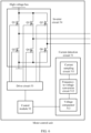
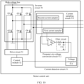
- FIG. 4 is a diagram of a structure of a motor control unit according to an embodiment of this application.
- the motor control unit may include an inverter circuit.
- the inverter circuit may include three bridge arms, each of the three bridge arms may include an upper bridge switching transistor and a lower bridge switching transistor, and bridge arm midpoints of the three bridge arms are respectively connected to three phase windings of a drive motor.
- a first bridge arm of the three bridge arms may include a switching transistor Q1 and a switching transistor Q2, a second bridge arm may include a switching transistor Q3 and a switching transistor Q4, and a third bridge arm may include a switching transistor Q5 and a switching transistor Q6.
- the first bridge arm, the second bridge arm, and the third bridge arm are connected in parallel.
- the switching transistor Q1 is connected to the switching transistor Q2 in series
- the switching transistor Q3 is connected to the switching transistor Q4 in series
- the switching transistor Q5 is connected to the switching transistor Q6 in series.
- the switching transistor Q1, the switching transistor Q3, and the switching transistor Q5 are upper bridge switching transistors
- the switching transistor Q2, the switching transistor Q4, and the switching transistor Q6 are lower bridge switching transistors.
- the first bridge arm, the second bridge arm, and the third bridge arm may be interchanged.
- the motor control unit runs in a normal operating state.
- the inverter circuit may run in a normal operating state.
- operating modes of the three upper bridge switching transistors Q1, Q3, and Q5 and the three lower bridge switching transistors Q2, Q4, and Q6 of the inverter circuit are all an alternate conduction mode.
- that the switching transistors are alternately conducted may be understood as that the switching transistors alternate between being conducted and being cut off, instead of being always in a conducted state or a cutoff state.
- the alternate conduction mode of the switching transistors may also be understood as that the switching transistors are conducted or cut off based on a pulse width modulation (pulse width modulation, PWM) signal.
- PWM pulse width modulation
- operating modes of the three upper bridge switching transistors Q1, Q3, and Q5 in the inverter circuit may be switched from an alternate conduction mode to a continuous conduction mode, and operating modes of the three lower bridge switching transistors Q2, Q4, and Q6 in the inverter circuit may be switched from an alternate conduction mode to a continuous cutoff mode; or operating modes of the three upper bridge switching transistors Q1, Q3, and Q5 in the inverter circuit may alternatively be switched from an alternate conduction mode to a continuous cutoff mode, and operating modes of the three lower bridge switching transistors Q2, Q4, and Q6 in the inverter circuit may alternatively be switched from an alternate conduction mode to a continuous conduction mode; or operating modes of the three upper bridge switching transistors Q1, Q3, and Q5 and the three lower bridge switching transistors Q2, Q4, and Q6 in the inverter circuit may alternatively be switched from an alternate conduction mode to a continuous cut
- operating modes of the three upper bridge switching transistors Q1, Q3, and Q5 and the three lower bridge switching transistors Q2, Q4, and Q6 in the inverter circuit may be switched from an alternate conduction mode to a continuous cutoff mode; or operating modes of the three upper bridge switching transistors Q1, Q3, and Q5 or the three lower bridge switching transistors Q2, Q4, and Q6 in the inverter circuit may alternatively be switched from a continuous conduction mode to a continuous cutoff mode.
- the first frequency threshold is greater than the second frequency threshold.
- the motor control unit When a processor-level fault occurs in the motor control unit, a rotational speed of the drive motor is high, and the electric vehicle is prone to a traffic accident. To ensure safety, the motor control unit needs to be switched from a normal operating state to an ASC state or an SPO state. Because the rotational speed of the drive motor is positively correlated with a current frequency of any phase winding in the three phase windings of the drive motor, in response to the current frequency of the at least one phase winding in the three phase windings of the drive motor being greater than or equal to the first frequency threshold, the motor control unit needs to be switched from the normal operating state to the ASC state or the SPO state.
- the motor control unit in response to a current frequency of at least one phase winding in the three phase windings of the drive motor being greater than or equal to the first frequency threshold, the motor control unit runs in an ASC state.
- the three upper bridge switching transistors Q1, Q3, and Q5 in the inverter circuit are in a continuous conduction mode or a short-circuit state, or the three lower bridge switching transistors Q2, Q4, and Q6 in the inverter circuit are in a continuous conduction mode or a short-circuit state.
- the three upper bridge switching transistors Q1, Q3, and Q5 in the inverter circuit may be switched from an alternate conduction mode to a continuous conduction mode, and the three lower bridge switching transistors Q2, Q4, and Q6 in the inverter circuit may be switched from an alternate conduction mode to a continuous cutoff mode.
- the three upper bridge switching transistors Q1, Q3, and Q5 in the inverter circuit are switched from an alternate conduction mode to a continuous cutoff mode, and the three lower bridge switching transistors Q2, Q4, and Q6 in the inverter circuit are switched from an alternate conduction mode to a continuous conduction mode.
- a running status of the motor control unit in response to the current frequency of the at least one phase winding in the three phase windings of the drive motor being greater than or equal to the first frequency threshold, a running status of the motor control unit is switched from a normal operating state to an SPO state.
- the operating modes of the three upper bridge switching transistors Q1, Q3, and Q5 and the three lower bridge switching transistors Q2, Q4, and Q6 in the inverter circuit are all in a continuous cutoff mode or a cutoff state.
- the operating modes of the three upper bridge switching transistors Q1, Q3, and Q5 and the three lower bridge switching transistors Q2, Q4, and Q6 in the inverter circuit may be switched from an alternate conduction mode to a continuous cutoff mode.
- the rotational speed of the drive motor is high, and in response to the current frequency of the at least one phase winding in the three phase windings of the drive motor being greater than or equal to the first frequency threshold, the running status of the motor control unit may be switched from a normal operating state to an ASC state, or may be switched from a normal operating state to an SPO state.
- the running status of the motor control unit in response to the current frequency of the at least one phase winding in the three phase windings of the drive motor being less than or equal to the second frequency threshold, the running status of the motor control unit is switched from the ASC state to the SPO state.
- the operating modes of the three upper bridge switching transistors Q1, Q3, and Q5 in the inverter circuit are a continuous cutoff mode, and the operating modes of the three lower bridge switching transistors Q2, Q4, and Q6 in the inverter circuit are switched from a continuous conduction mode to a continuous cutoff mode.
- the running status of the motor control unit in response to the current frequency of the at least one phase winding in the three phase windings of the drive motor being less than or equal to the second frequency threshold, the running status of the motor control unit may be switched from a normal operating state to an SPO state.
- the operating modes of the three upper bridge switching transistors Q1, Q3, and Q5 and the three lower bridge switching transistors Q2, Q4, and Q6 in the inverter circuit may be switched from an alternate conduction mode to a continuous cutoff mode.
- the motor control unit detects the rotational speed of the drive motor by detecting the current frequency of the at least one phase winding in the three phase windings of the drive motor.
- the motor control unit runs in the ASC state, and when the rotational speed of the drive motor is low, the motor control unit runs in the SPO state.
- the motor control unit detects the rotational speed of the drive motor by detecting the current frequency of the at least one phase winding in the three phase windings of the drive motor.
- the motor control unit When the rotational speed of the drive motor is high, the motor control unit runs in the SPO state, and when the rotational speed of the drive motor is low, the motor control unit runs in the ASC state.
- the motor control unit provided in this embodiment of this application can further limit duration in which the motor control unit runs in the ASC state or the SPO state, to reduce a thermal failure risk of the motor control unit and the drive motor, and avoid generation of unexpected torque, thereby improving safety of the electric vehicle.
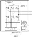
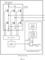
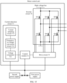
- FIG. 5 is a diagram of a structure of another motor control unit according to an embodiment of this application.
- the motor control unit includes a current detection circuit 51, a control module 52, a drive circuit 53, and an inverter circuit 54.
- An output end of the current detection circuit 51 is connected to an input end of the control module 52
- an output end of the control module 52 is connected to an input end of the drive circuit 53
- an output end of the drive circuit 53 is connected to the inverter circuit 54.
- the output end of the drive circuit 53 is connected to control ends of six switching transistors Q1 to Q6 in the inverter circuit 54.
- the switching transistor is an MOSFET
- the control end of the switching transistor is a gate of the MOSFET.
- the motor control unit provided in this embodiment of this application may further include another type of switching transistor, and a control end of the another type of switching transistor may have another name.
- the current detection circuit 51 is configured to detect a current frequency of at least one phase winding in three phase windings of a drive motor. In response to a current frequency of at least one phase winding in the three phase windings of the drive motor being greater than or equal to a first frequency threshold, the current detection circuit 51 outputs a first detection signal indicating that a rotational speed of the drive motor is greater than or equal to a first threshold. If the rotational speed of the drive motor is greater than or equal to the first threshold, it indicates that the rotational speed of the drive motor is high.
- the current detection circuit 51 can always run in an operating state, thereby improving timeliness of fault handling by the motor control unit. For example, when no processor-level fault occurs in the motor control unit, the control module 52, the drive circuit 53, and the inverter circuit 54 do not respond to the first detection signal or the second detection signal output by the current detection circuit 51. That is, the control module 52, the drive circuit 53, and the inverter circuit 54 may ignore the first detection signal or the second detection signal output by the current detection circuit 51.
- the current detection circuit 51 is in an operating state only when a processor-level fault occurs in the motor control unit. This reduces complexity of a control policy of the motor control unit. For example, when no processor-level fault occurs in the motor control unit, the current detection circuit 51 is in a non-operating state. When a processor-level fault occurs in the motor control unit, the current detection circuit 51 is in an operating state.
Landscapes
- Engineering & Computer Science (AREA)
- Power Engineering (AREA)
- Transportation (AREA)
- Mechanical Engineering (AREA)
- Control Of Ac Motors In General (AREA)
Applications Claiming Priority (2)
| Application Number | Priority Date | Filing Date | Title |
|---|---|---|---|
| CN202211166836.XA CN115580201A (zh) | 2022-09-23 | 2022-09-23 | 一种电机控制器、动力总成及电动汽车 |
| PCT/CN2023/105293 WO2024060785A1 (zh) | 2022-09-23 | 2023-06-30 | 一种电机控制器、动力总成及电动汽车 |
Publications (2)
| Publication Number | Publication Date |
|---|---|
| EP4531270A1 true EP4531270A1 (de) | 2025-04-02 |
| EP4531270A4 EP4531270A4 (de) | 2025-09-24 |
Family
ID=84581508
Family Applications (1)
| Application Number | Title | Priority Date | Filing Date |
|---|---|---|---|
| EP23867080.6A Pending EP4531270A4 (de) | 2022-09-23 | 2023-06-30 | Motorsteuerung, antriebsstrang und elektrofahrzeug |
Country Status (4)
| Country | Link |
|---|---|
| US (1) | US20250219563A1 (de) |
| EP (1) | EP4531270A4 (de) |
| CN (1) | CN115580201A (de) |
| WO (1) | WO2024060785A1 (de) |
Families Citing this family (3)
| Publication number | Priority date | Publication date | Assignee | Title |
|---|---|---|---|---|
| CN115580201A (zh) * | 2022-09-23 | 2023-01-06 | 华为数字能源技术有限公司 | 一种电机控制器、动力总成及电动汽车 |
| CN116278686A (zh) * | 2023-04-03 | 2023-06-23 | 华为数字能源技术有限公司 | 动力总成、电机控制器、电动汽车 |
| CN117104019A (zh) * | 2023-08-28 | 2023-11-24 | 华为数字能源技术有限公司 | 电机控制器、电驱动系统及车辆 |
Family Cites Families (11)
| Publication number | Priority date | Publication date | Assignee | Title |
|---|---|---|---|---|
| JP2520718B2 (ja) * | 1989-02-14 | 1996-07-31 | 株式会社荏原製作所 | タ―ボ分子ポンプ駆動電源装置 |
| US7279862B1 (en) * | 2006-08-04 | 2007-10-09 | Gm Global Technology Operations, Inc. | Fault handling of inverter driven PM motor drives |
| DE102012002023A1 (de) * | 2011-06-21 | 2012-12-27 | Volkswagen Aktiengesellschaft | Verfahren und Vorrichtung zum Betreiben einer Wechselrichterschaltung einer Elektromaschine |
| US10351002B2 (en) * | 2014-11-14 | 2019-07-16 | Aisin Aw Co., Ltd. | Inverter control device and vehicle control device |
| CN106696753B (zh) * | 2015-07-24 | 2019-08-09 | 长城汽车股份有限公司 | 电机控制装置及电机控制方法 |
| CN109873556B (zh) * | 2017-12-01 | 2020-03-17 | 维谛技术有限公司 | 一种三电平逆变器的限流控制方法和装置 |
| JP7371356B2 (ja) * | 2019-06-05 | 2023-10-31 | 富士電機株式会社 | モータ速度検出器及びインバータ装置 |
| CN112468057B (zh) * | 2020-10-10 | 2025-06-10 | 蔚来汽车科技(安徽)有限公司 | 用于车辆的电机控制方法和电路、电机驱动系统以及车辆 |
| CN112572151A (zh) * | 2020-10-30 | 2021-03-30 | 深圳市禾望电气股份有限公司 | 电机的主动短路保护方法、控制器以及电机控制系统 |
| CN114670637B (zh) * | 2021-12-10 | 2024-06-25 | 北京新能源汽车股份有限公司 | 三相电流零漂故障检测的方法、电机控制器及驱动系统 |
| CN115580201A (zh) * | 2022-09-23 | 2023-01-06 | 华为数字能源技术有限公司 | 一种电机控制器、动力总成及电动汽车 |
-
2022
- 2022-09-23 CN CN202211166836.XA patent/CN115580201A/zh active Pending
-
2023
- 2023-06-30 WO PCT/CN2023/105293 patent/WO2024060785A1/zh not_active Ceased
- 2023-06-30 EP EP23867080.6A patent/EP4531270A4/de active Pending
-
2025
- 2025-03-21 US US19/087,407 patent/US20250219563A1/en active Pending
Also Published As
| Publication number | Publication date |
|---|---|
| CN115580201A (zh) | 2023-01-06 |
| US20250219563A1 (en) | 2025-07-03 |
| EP4531270A4 (de) | 2025-09-24 |
| WO2024060785A1 (zh) | 2024-03-28 |
Similar Documents
| Publication | Publication Date | Title |
|---|---|---|
| EP4531270A1 (de) | Motorsteuerung, antriebsstrang und elektrofahrzeug | |
| CN109039221B (zh) | 一种主动短路电路以及电机控制器 | |
| EP3648274B1 (de) | Schutzkoordinationstechnik für stromwandler | |
| EP3575126B1 (de) | Motorsteuergerät | |
| JP4714273B2 (ja) | 電力系のための過電圧制御システムおよび過電圧制御方法 | |
| EP1811645A1 (de) | Stromversorgungsschaltungs-schutzverfahren und vorrichtung dafür | |
| US20090059446A1 (en) | AC Motor Controller | |
| CN110350486A (zh) | 故障保护装置、变频器及电机驱动系统 | |
| EP4087077A1 (de) | Elektrisches motorsteuerungssystem und elektrische motorsteuervorrichtung | |
| US12500511B2 (en) | Capacitor embedded rogowski current detection | |
| US7514906B1 (en) | Automotive rotary electrical apparatus | |
| CN114566938A (zh) | 碳化硅功率mosfet的过流保护装置、方法、电子设备及介质 | |
| JP3999226B2 (ja) | 電動機制御装置 | |
| CN114614688A (zh) | 用于逆变器的保护装置、逆变器系统以及电动车辆 | |
| EP3473483B1 (de) | Wechselrichter für eine elektrische maschine, elektrische maschine für ein fahrzeug, fahrzeug und verfahren zum betrieb eines wechselrichters | |
| US11894791B2 (en) | Control device, motor driving apparatus, and motor driving system | |
| US12199422B2 (en) | Systems and methods for overcurrent protection | |
| CN223156989U (zh) | 电源电路及驱动器 | |
| CN112994558A (zh) | 异步电机控制器 | |
| CN221851715U (zh) | 车辆及保护电路 | |
| CN223062930U (zh) | 一种混合式磁悬浮轴承驱动器 | |
| CN220754348U (zh) | 母线过流保护电路、用电设备以及电源装置 | |
| US12308741B2 (en) | Buck circuit, buck apparatus, and circuit control method | |
| JP2001037244A (ja) | 電力変換装置 | |
| US11811350B2 (en) | Motor control system and motor control apparatus |
Legal Events
| Date | Code | Title | Description |
|---|---|---|---|
| STAA | Information on the status of an ep patent application or granted ep patent |
Free format text: STATUS: THE INTERNATIONAL PUBLICATION HAS BEEN MADE |
|
| PUAI | Public reference made under article 153(3) epc to a published international application that has entered the european phase |
Free format text: ORIGINAL CODE: 0009012 |
|
| STAA | Information on the status of an ep patent application or granted ep patent |
Free format text: STATUS: REQUEST FOR EXAMINATION WAS MADE |
|
| 17P | Request for examination filed |
Effective date: 20241223 |
|
| AK | Designated contracting states |
Kind code of ref document: A1 Designated state(s): AL AT BE BG CH CY CZ DE DK EE ES FI FR GB GR HR HU IE IS IT LI LT LU LV MC ME MK MT NL NO PL PT RO RS SE SI SK SM TR |
|
| REG | Reference to a national code |
Ref country code: DE Ref legal event code: R079 Free format text: PREVIOUS MAIN CLASS: H02P0027060000 Ipc: H02P0003220000 |
|
| A4 | Supplementary search report drawn up and despatched |
Effective date: 20250825 |
|
| RIC1 | Information provided on ipc code assigned before grant |
Ipc: H02P 3/22 20060101AFI20250819BHEP Ipc: H02P 23/00 20160101ALI20250819BHEP Ipc: H02P 23/14 20060101ALI20250819BHEP Ipc: H02P 29/024 20160101ALI20250819BHEP Ipc: H02M 1/32 20070101ALI20250819BHEP Ipc: H02M 7/5387 20070101ALI20250819BHEP Ipc: H02M 1/00 20060101ALI20250819BHEP |
|
| DAV | Request for validation of the european patent (deleted) | ||
| DAX | Request for extension of the european patent (deleted) |