EP4530684A2 - Luminaires à faisceau réglable - Google Patents
Luminaires à faisceau réglable Download PDFInfo
- Publication number
- EP4530684A2 EP4530684A2 EP25156461.3A EP25156461A EP4530684A2 EP 4530684 A2 EP4530684 A2 EP 4530684A2 EP 25156461 A EP25156461 A EP 25156461A EP 4530684 A2 EP4530684 A2 EP 4530684A2
- Authority
- EP
- European Patent Office
- Prior art keywords
- light
- array
- light sources
- luminaire
- lightguide
- Prior art date
- Legal status (The legal status is an assumption and is not a legal conclusion. Google has not performed a legal analysis and makes no representation as to the accuracy of the status listed.)
- Pending
Links
Images


Classifications
-
- F—MECHANICAL ENGINEERING; LIGHTING; HEATING; WEAPONS; BLASTING
- F21—LIGHTING
- F21V—FUNCTIONAL FEATURES OR DETAILS OF LIGHTING DEVICES OR SYSTEMS THEREOF; STRUCTURAL COMBINATIONS OF LIGHTING DEVICES WITH OTHER ARTICLES, NOT OTHERWISE PROVIDED FOR
- F21V14/00—Controlling the distribution of the light emitted by adjustment of elements
- F21V14/06—Controlling the distribution of the light emitted by adjustment of elements by movement of refractors
-
- F—MECHANICAL ENGINEERING; LIGHTING; HEATING; WEAPONS; BLASTING
- F21—LIGHTING
- F21K—NON-ELECTRIC LIGHT SOURCES USING LUMINESCENCE; LIGHT SOURCES USING ELECTROCHEMILUMINESCENCE; LIGHT SOURCES USING CHARGES OF COMBUSTIBLE MATERIAL; LIGHT SOURCES USING SEMICONDUCTOR DEVICES AS LIGHT-GENERATING ELEMENTS; LIGHT SOURCES NOT OTHERWISE PROVIDED FOR
- F21K9/00—Light sources using semiconductor devices as light-generating elements, e.g. using light-emitting diodes [LED] or lasers
- F21K9/60—Optical arrangements integrated in the light source, e.g. for improving the colour rendering index or the light extraction
- F21K9/61—Optical arrangements integrated in the light source, e.g. for improving the colour rendering index or the light extraction using light guides
-
- F—MECHANICAL ENGINEERING; LIGHTING; HEATING; WEAPONS; BLASTING
- F21—LIGHTING
- F21V—FUNCTIONAL FEATURES OR DETAILS OF LIGHTING DEVICES OR SYSTEMS THEREOF; STRUCTURAL COMBINATIONS OF LIGHTING DEVICES WITH OTHER ARTICLES, NOT OTHERWISE PROVIDED FOR
- F21V17/00—Fastening of component parts of lighting devices, e.g. shades, globes, refractors, reflectors, filters, screens, grids or protective cages
- F21V17/02—Fastening of component parts of lighting devices, e.g. shades, globes, refractors, reflectors, filters, screens, grids or protective cages with provision for adjustment
-
- F—MECHANICAL ENGINEERING; LIGHTING; HEATING; WEAPONS; BLASTING
- F21—LIGHTING
- F21V—FUNCTIONAL FEATURES OR DETAILS OF LIGHTING DEVICES OR SYSTEMS THEREOF; STRUCTURAL COMBINATIONS OF LIGHTING DEVICES WITH OTHER ARTICLES, NOT OTHERWISE PROVIDED FOR
- F21V5/00—Refractors for light sources
- F21V5/007—Array of lenses or refractors for a cluster of light sources, e.g. for arrangement of multiple light sources in one plane
-
- F—MECHANICAL ENGINEERING; LIGHTING; HEATING; WEAPONS; BLASTING
- F21—LIGHTING
- F21V—FUNCTIONAL FEATURES OR DETAILS OF LIGHTING DEVICES OR SYSTEMS THEREOF; STRUCTURAL COMBINATIONS OF LIGHTING DEVICES WITH OTHER ARTICLES, NOT OTHERWISE PROVIDED FOR
- F21V7/00—Reflectors for light sources
- F21V7/0008—Reflectors for light sources providing for indirect lighting
-
- G—PHYSICS
- G02—OPTICS
- G02B—OPTICAL ELEMENTS, SYSTEMS OR APPARATUS
- G02B19/00—Condensers, e.g. light collectors or similar non-imaging optics
- G02B19/0004—Condensers, e.g. light collectors or similar non-imaging optics characterised by the optical means employed
- G02B19/0028—Condensers, e.g. light collectors or similar non-imaging optics characterised by the optical means employed refractive and reflective surfaces, e.g. non-imaging catadioptric systems
-
- G—PHYSICS
- G02—OPTICS
- G02B—OPTICAL ELEMENTS, SYSTEMS OR APPARATUS
- G02B19/00—Condensers, e.g. light collectors or similar non-imaging optics
- G02B19/0033—Condensers, e.g. light collectors or similar non-imaging optics characterised by the use
- G02B19/0047—Condensers, e.g. light collectors or similar non-imaging optics characterised by the use for use with a light source
- G02B19/0061—Condensers, e.g. light collectors or similar non-imaging optics characterised by the use for use with a light source the light source comprising a LED
- G02B19/0066—Condensers, e.g. light collectors or similar non-imaging optics characterised by the use for use with a light source the light source comprising a LED in the form of an LED array
-
- G—PHYSICS
- G02—OPTICS
- G02B—OPTICAL ELEMENTS, SYSTEMS OR APPARATUS
- G02B26/00—Optical devices or arrangements for the control of light using movable or deformable optical elements
- G02B26/08—Optical devices or arrangements for the control of light using movable or deformable optical elements for controlling the direction of light
- G02B26/0875—Optical devices or arrangements for the control of light using movable or deformable optical elements for controlling the direction of light by means of one or more refracting elements
-
- G—PHYSICS
- G02—OPTICS
- G02B—OPTICAL ELEMENTS, SYSTEMS OR APPARATUS
- G02B6/00—Light guides; Structural details of arrangements comprising light guides and other optical elements, e.g. couplings
- G02B6/0001—Light guides; Structural details of arrangements comprising light guides and other optical elements, e.g. couplings specially adapted for lighting devices or systems
- G02B6/0011—Light guides; Structural details of arrangements comprising light guides and other optical elements, e.g. couplings specially adapted for lighting devices or systems the light guides being planar or of plate-like form
- G02B6/0033—Means for improving the coupling-out of light from the light guide
- G02B6/0035—Means for improving the coupling-out of light from the light guide provided on the surface of the light guide or in the bulk of it
- G02B6/0036—2-D arrangement of prisms, protrusions, indentations or roughened surfaces
-
- G—PHYSICS
- G02—OPTICS
- G02B—OPTICAL ELEMENTS, SYSTEMS OR APPARATUS
- G02B6/00—Light guides; Structural details of arrangements comprising light guides and other optical elements, e.g. couplings
- G02B6/0001—Light guides; Structural details of arrangements comprising light guides and other optical elements, e.g. couplings specially adapted for lighting devices or systems
- G02B6/0011—Light guides; Structural details of arrangements comprising light guides and other optical elements, e.g. couplings specially adapted for lighting devices or systems the light guides being planar or of plate-like form
- G02B6/0033—Means for improving the coupling-out of light from the light guide
- G02B6/005—Means for improving the coupling-out of light from the light guide provided by one optical element, or plurality thereof, placed on the light output side of the light guide
- G02B6/0055—Reflecting element, sheet or layer
-
- F—MECHANICAL ENGINEERING; LIGHTING; HEATING; WEAPONS; BLASTING
- F21—LIGHTING
- F21Y—INDEXING SCHEME ASSOCIATED WITH SUBCLASSES F21K, F21L, F21S and F21V, RELATING TO THE FORM OR THE KIND OF THE LIGHT SOURCES OR OF THE COLOUR OF THE LIGHT EMITTED
- F21Y2105/00—Planar light sources
-
- F—MECHANICAL ENGINEERING; LIGHTING; HEATING; WEAPONS; BLASTING
- F21—LIGHTING
- F21Y—INDEXING SCHEME ASSOCIATED WITH SUBCLASSES F21K, F21L, F21S and F21V, RELATING TO THE FORM OR THE KIND OF THE LIGHT SOURCES OR OF THE COLOUR OF THE LIGHT EMITTED
- F21Y2115/00—Light-generating elements of semiconductor light sources
- F21Y2115/10—Light-emitting diodes [LED]
-
- G—PHYSICS
- G02—OPTICS
- G02B—OPTICAL ELEMENTS, SYSTEMS OR APPARATUS
- G02B26/00—Optical devices or arrangements for the control of light using movable or deformable optical elements
- G02B26/08—Optical devices or arrangements for the control of light using movable or deformable optical elements for controlling the direction of light
-
- G—PHYSICS
- G02—OPTICS
- G02B—OPTICAL ELEMENTS, SYSTEMS OR APPARATUS
- G02B3/00—Simple or compound lenses
- G02B3/0006—Arrays
Definitions
- the present invention relates to optics, specifically to optical systems for controlling beam properties in illumination.
- Directional lighting is important in many contexts, for example in providing illumination for task areas in a workplace, for highlighting objects in a retail space or an artistic exhibition, for illuminating walkways and roadways outdoors, and many more applications.
- Commonly-used light fixtures that provide the option to adjust lighting directionality typically include an illumination "head" that can be swiveled to point in a desired direction. Multiple heads are often included in a single light bank or in a configurable system such as a track lighting system. Adjustments to the angular spread of the output beam from each head is typically achieved by installing a bulb with the desired output beam width.
- a planar adjustable luminaire design of prior art is disclosed in Joseph Ford PCT/US2014/057873 "Microstructured Waveguide Illuminator” and William M. Mellette, Glenn M. Schuster, and Joseph E. Ford, "Planar waveguide LED illuminator with controlled directionality and divergence,” Optics Express vol. 22 No. S3, 2014 (Mellette et al ).
- This design offers the potential advantage of a compact low-profile form factor with wide adjustability.
- the luminaire uses an edge-illuminated lightguide with periodic extraction features that is mated to an array of refractive lenses or reflectors ("focusing elements").
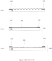
- Figure 1 provides an exploded view of such a design. It includes a lightguide 10 that is illuminated by a light source 11, in this example composed of light emitting diodes (LEDs) 20 and associated coupler optics 18.
- the lightguide 10 may be of a continuous-mode type as shown in Figure 1 or a stepped-mode type. In either case, the lightguide includes a periodic array of extraction features 12. These features reflect or scatter light so that it is no longer trapped in guided modes of the lightguide and instead exits the lightguide to interact with the array of focusing refractive lenses 24.
- the extraction features shown in Figure 1 are reflective and are preferably shaped as prisms to deflect guided light toward the focusing elements, but may also be shaped as cones, hemispheres, or other shapes. They lie approximately in the focal plane of the focusing elements so that light scattered by the extraction elements is substantially collimated by the focusing elements.
- the refractive lens array 24 is composed of individual refractive lenses 25 all in a single plane. The lenses 25 substantially collimate the light before it exits the luminaire into the environment.
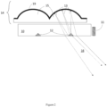
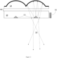
- Figure 2 is a cross-section view of a portion of an adjustable luminaire of prior art that uses reflective focusing elements.
- the array of reflectors 14 is composed of dielectric-filled reflective lenses 15 with reflective coating 19.
- One extraction feature 12 is associated with each reflective lens.
- Light from the light source 11 is guided in the lightguide 10. Some of the light is deflected by extraction features 12 to exit the guide 10 and enter the reflector array 14. These light rays 13 reflect off the reflective coating 19 becoming partially collimated, and then transit through the lightguide 10 before exiting the luminaire as output light beam 16. Note that light rays emanating from the light source 11 and traveling within the guide 10 are not depicted in Figure 2 in the interest of visual clarity; only example light rays 13 deflected by one of the extraction elements 12 are shown.
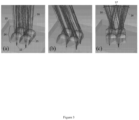
- FIG 3 is a ray trace diagram showing an example four-lens refractive focusing element array in the luminaire of prior art. The figure demonstrates control over the characteristics of the output beam of the luminaire.
- Each individual lens 25 serves to substantially collimate the light reflected or scattered by the corresponding extraction feature 12 so that it is emitted into the environment as a directional beam 16 of narrow angular width. Control over the directionality of the individual beams 16 is achieved by varying the relative location of the extraction feature 12 and the lens 25. This can be achieved by translating the array of lenses 24 relative to the extraction features 12 in the lightguide. As the location of the extraction feature 12 moves from the center of the lens 25 (as in Figure 3a ) to the edge (as in Figure 3b ), the output beam 16 is steered from perpendicular to the plane of the lightguide to a high angle.
- Mellette et al also discusses using an array of point-like LED sources in place of the lightguide, but teaches that the idea is impractical in its various embodiments.
- the idea is described as having a thicker form factor than a system comprising a lightguide, categorically not allowing for the use of reflective lenses, and incapable of matching the efficiency and total brightness of a system comprising a lightguide.
- Mellette et al specify the use of the Cree XM-L2 LED, which is a large LED with a tall integrated silicone dome and their drawings depict domed LEDs.
- a variety of light sources may be used in the edge-lit luminaire device.
- these include light-emitting diode (LED) and laser diode (LD) sources.
- LED light-emitting diode
- LD laser diode
- These light sources are attractive as they are small and can operate at high optical efficiency.
- these sources are often utilized with one or more downconversion materials such as phosphors that convert a portion of the light to lower-energy longer-wavelength light.
- the downconversion medium is placed directly on the LED or LD device to form a white-light-emitting component. Placing the downconversion materials away from the LED source improves efficiency by reducing the amount of light scattered back into the LED source.
- the luminaire comprises MCPCB 32 and small and flat LEDs as the light source 30 to minimize shadowing, as shown in Figure 5 .
- the edge-lit design can be implemented with high optical efficiency in a small form factor.
- the edge-lit design can require an array of a certain length in order to achieve a target optical efficiency, because of the requirement to extract light from a lightguide.
- the edge-lit design requires a certain thickness of lightguide 10 to maintain a flat shape when fabricated of plastic materials, to have sufficient mechanical toughness against breakage when fabricated of any transparent materials, and to provide for sufficient in-coupling of light from light source 11; for example, this thickness can be 1.5mm to 5mm and the required thickness increases as the size of the lightguide 10 increases.
- the direct-lit design can be produced with any number of light sources in an array, including even only a single light source.
- the elongation may optionally be extended to the entire width of the focusing element.
- This invention may also be realized in a direct-lit luminaire by utilizing elongated light sources or multiple light sources arrayed in an elongated pattern.
- a ceiling-mounted luminaire of prior art will produce a symmetric beam that results in an elongated projected spot of uneven brightness when projected onto a vertical wall.
- An improved luminaire designed for such an application can counteract this by tailoring the size and relative position of the extraction features and focusing elements within the array to produce an asymmetric beam.
- Each extraction feature produces an output beam, and the aggregate output beam is the sum of these individual beams.
- the arrays may be designed with non-matching periodicity, so that beams of different pointing angles are produced by different focusing elements.
- the intensity of the aggregate beam across these different beam angles may be tailored by adjusting the number of focusing elements outputting at each angle in order to provide the desired asymmetric beam profile.
- the asymmetric beam may be steered and broadened using the same mechanisms described above.
- Extraction features 150 share the periodicity of the reflector array 14 and are centered with respect to their associated focusing elements, while extraction features 151 do not share the periodicity of the focusing element array and are spread so that each extraction feature 151 is differently aligned to its associated focusing element, in this case ranging from centered to offset at one edge.
- the resulting output beam profile 152 as shown in Figure 8b , has a central lobe formed primarily by the extraction features 150 and is extended asymmetrically in one direction as a result of the extraction features 151.
- Another use of this invention is to provide beam pointing that varies in a deterministic way with position in the focusing element array.
- a luminaire that provides a steerable spotlight in a linear form factor with a high aspect ratio may be desired.
- Such a luminaire could have an example length of between 12 and 36 inches.
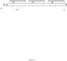
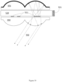
- FIG. 9 depicts a luminaire in which the periodicity of the extraction features 12 is slightly larger than that of the reflector array 14.
- the beams 160 and 164 from the ends of the array tend to converge toward the center, combining with beam 162 to form a narrow spot at a desired distance from the luminaire.
- the prior art steerable luminaire describes the use of single refractive lens array (as in Figure 3 ) or reflector array (as in Figure 2 ).
- Figure 10 describes a new option: the use of catadioptric optics that combine both a reflector array 50 and a refractive lens array 51.
- One reflector and one refractive lens are associated with each extraction element 12 (or with each light source if used in a direct-lit configuration, not shown).
- the extraction features 12 sit at the approximate focal plane of the combined focusing elements made of the reflector and refractive lens arrays.
- the reflector array 50 and refractive lens array 51 are kept in permanent alignment to one another, and move relative to the lightguide extraction features 12 in order to provide beam steering and beam broadening.
- FIG. 10 describes an edge-lit embodiment of this invention, it can also be realized in a direct-lit configuration by utilizing an array of light sources rather than an array of extraction features in an edge-lit lightguide.
- the prior art designs envisioned focusing elements that are rotationally symmetric, therefore providing a symmetric output beam.
- An additional option is to use focusing elements that have toroidal surfaces characterized by a different radius of curvature and different aspheric terms in the two primary axes. This results in oval-shaped output beams, which can be advantageous in various situations.
- the focusing elements may be made cylindrical so that they provide focusing in one axis only, leaving the other axis unfocused. Examples of applications that can benefit from oval-shaped output beams include lighting of linear spaces such as hallways, and lighting of vertical surfaces (such as wall-mounted art), where an oval beam shape can be used to counter the tendency of a symmetric beam to become stretched when projected onto the vertical surface.
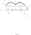
- Figure 11 shows a system using a reflector array 14 and an edge-lit lightguide 10 with extraction features 12.
- the gap 60 between the reflector array 14 and the lightguide 10 may be dynamically varied. Doing so causes the extraction features 12 to move in and out of the focus of the reflector elements in 14, causing the output beam 16 to narrow and widen.
- beam width modulation is provided by translating the reflector array 14 relative to the lightguide 10 in the direction perpendicular to the lightguide 10 (the "z-axis"). Further, this translational control of beam width may be combined with in-plane twisting actuation if desired.
- Figure 11 describes an edge-lit embodiment of this invention, it can also be realized in a direct-lit configuration by utilizing an array of light sources rather than an array of extraction features in an edge-lit lightguide.
- One mechanism is to introduce scattering elements randomly distributed in the lightguide so that a fraction of the guided light is scattered out and forms a broad-angle aggregate beam.
- the scattering elements may also be placed in the focusing element array if desired.
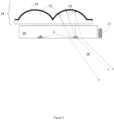
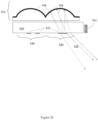
- Figure 12 Another mechanism is shown in Figure 12 .
- This design uses a reflector array 14 with a reflective coating 70 that is partially transparent and partially reflective.
- the portion of the light that is transmitted through the reflective coating 70 exits in a broad upward beam 71 forming a broad-beam uplight, while the portion of the beam that is reflected forms an adjustable directional downlight beam 16.
- Figure 12 describes an edge-lit embodiment of this invention, it can also be realized in a direct-lit configuration by utilizing an array of light sources rather than an array of extraction features in an edge-lit lightguide.
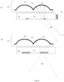
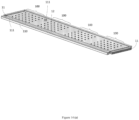
- FIG. 13 depicts a new system design, which can include multiple independently-adjustable reflector arrays 14.
- the reflector arrays are utilized with a rectangular lightguide 10 that has extraction features 12 in multiple arrays corresponding to each of the reflector arrays 14.
- the light guide is edge-lit by light sources 11 that may be present on one or more sides of the lightguide, with the unlit sides optionally coated by a reflective material to increase optical efficiency.
- Each of the reflector arrays 14 produces a separate aggregate output beam that can be independently pointed and adjusted via in-plane translation and twist, and/or z-axis translation.
- the system is unique and novel in providing a number of independently-adjustable directional lights from a common light source and a single fixture. For an edge-lit system, the longer optical path length that may be used with multiple independent arrays increases the light extraction efficiency of the system.
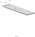
- Figure 14a depicts a modular system in which a lightguide 10 is provided with multiple arrays of extraction features 12, each such array providing an attachment location 100 for a modular output device. Each such location 100 can be utilized to form a directional beam or a broad area beam by the choice of attachment placed adjacent to the light guide.
- the attachments are shown in Figures 14b, 14c, and 14d . They may be attached adj acent to the light guide by any number of means.
- One example attachment mechanism is the use of magnetic attraction to hold the attachments in place, while still permitting them to be translated and twisted for output beam control.
- This magnetic attachment scheme uses magnetic materials 111 and 112 embedded in the frame 110 around the lightguide 10 and in the attachment parts respectively.
- At least one of the magnetic materials 111 and 112 is a permanent magnet, while the other may be a ferromagnetic material.
- the mounting of the attachments maintains a gap between the lightguide and the attachment. This gap may be filled with air or another low-refractive-index material to serve as cladding for the light guide.
- the reflector array 14 shown in Figure 14b is placed adjacent to the light guide in location 100, it will provide an adjustable directional light output as described earlier.
- the attachment can be positioned by sliding the attachment against the magnetic material 111 in the frame, allowing the reflector array 14 to be translated and twisted relative to the extraction features 12.
- Figure 14c shows another attachment option: a broad-area reflector 101.
- This reflector is formed by an optional transparent layer 102 and a reflective layer 103.
- the reflective layer 103 may be specularly reflective or scattering in nature. In either case, placement of the broad-area reflector 101 in the attachment location 100 results in a broad downward beam output.
- Figure 14d shows another attachment option: an uplight attachment 104.
- the uplight attachment consists of an optional transparent layer 105 and an optional diffusive layer 106 that diffuses light. Placement of the uplight attachment 104 in the attachment location 100 results in a broad-beam uplight output. Such output can also be achieved by leaving the attachment location 100 without an attachment.
- Another option is an attachment providing a combination of uplight and downlight by utilizing a partially transmissive and partially reflecting coating.
- FIG. 14 describes an edge-lit embodiment of this invention, it can also be realized in a direct-lit configuration by utilizing an array of light sources rather than an array of extraction features in an edge-lit lightguide.
- FIG. 15 A further modification to this system design is shown in Figure 15 .
- the lightguide 10 is provided without extraction features.
- the arrays of extraction features 12 are instead prepared in a separate extraction array material 120.
- Each extraction array material 120 consists of a transparent layer of rigid or flexible material with a single array of extraction features 12 embedded within it.
- the extraction array material 120 can be placed on the lightguide 10 wherever is desired in order to produce an attachment location 100 for light output. In each such location, a reflector array 14 may be placed (as shown), or other attachments may be used.
- Multiple extraction array materials 120 can be utilized with a single long lightguide, allowing directional output beams to be placed wherever desired along a track.
- the extraction array materials 120 In order to ensure effective light extraction, the extraction array materials 120 must be mated to the lightguide 10 with no air gap, so that light transits from the lightguide 10 into the extraction array material 120.
- the extraction array materials may incorporate a transparent adhesive layer, or may be made of materials that "cling" effectively to the lightguide 10.
- Adjustment of the beam properties is achieved by altering the relative placement and orientation of the focusing element array and the lightguide, with its array of extraction features. Many mechanical configurations are possible for manual or motorized adjustment of the relative location for these two pieces.
- the magnetic mounting scheme shown in Figure 14 is one such system.
- the focusing element array may be moved relative to the light guide by hand, either by sliding it directly or with any sort of handle attachments.
- a handle attachment protruding from the focusing element array could be combined with a pivot to provide a joystick-type actuation mechanism.
- Figure 16 shows a top view of another mechanical configuration permitting adjustment of the relative orientation of the lightguide and the focusing element array.
- a reflector array 14 is in contact with three cams (121, 122, and 123) mounted to stationary frame 126.
- the reflector array is held against the cams by leaf springs 124.
- One side of the reflector array is in contact with a single cam 121.
- the rotational position of this cam controls translation of the array in one axis (labeled here as the "x" axis).
- a perpendicular side of the array is in contact with two cams 122 and 123.
- the "y" axis translation of the lens array is controlled by adjusting cams 122 and 123 together and is set by their average extension, while twist rotation of the lens array is controlled by adjusting cams 122 and 123 separately and is set by the difference between the extension of these two cams.
- the cams may be connected to knobs for manual control over beam direction and width, or connected to motors for automated control.
- Figure 16 depicts the cams and leaf springs in contact with the edges of the edges of the reflector array, but they could also act on the reflector array from other locations, for example on small protrusions attached to the center of the reflector array. Such a design would provide a more compact luminaire form factor by allowing the cams and leaf springs to fit within the perimeter of the reflector array and/or light guide.
- leaf springs may be replaced with other mechanisms for providing restoring force, such as wound springs, compressible materials, etc.
- Figure 16 describes an edge-lit embodiment of this invention, it can also be realized in a direct-lit configuration by utilizing an array of light sources rather than an array of extraction features in an edge-lit lightguide.
- the luminaire may be configured to allow beam pointing in only one axis, or in two axes by appropriately constraining translation of the focusing element array relative to the lightguide or light source array. Further, the entire luminaire may be mounted in a frame to swivel in one or two axes, to provide additional mechanisms of beam pointing. For example, a luminaire with a rectangular form factor could be designed to swivel in a frame about its long axis and to provide beam pointing in the other axis via translation of the focusing element array relative to the lightguide or light source array.
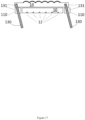
- FIG. 17 provides an example of a system with integrated louvers to provide such glare reduction.
- the louvers 130 are made of an opaque material and attached to a frame element 110 and the reflector array with pivoting connectors 131. As the reflector array 14 is translated to steer the beam, the louvers 130 automatically tilt to block light outside the steered beam. While Figure 17 describes an edge-lit embodiment of this invention, it can also be realized in a direct-lit configuration by utilizing an array of light sources rather than an array of extraction features in an edge-lit lightguide.
- a cover layer 190 is placed adjacent to the lightguide 10 on the side opposite the reflector array 14, and separated from the lightguide by a gap 191 over the majority of the area of the lightguide.
- the gap 191 may be filled with air and maintained by the use of a frame that holds the cover layer 190 apart from the lightguide 10, by small spacers placed between the lightguide 10 and the cover layer 190, by the natural surface roughness of the cover layer, or by any combination of these or other schemes.
- the gap may be filled by another low-refractive index material.
- the gap is preferably large enough to ensure total internal reflection within the lightguide 10 so that very little of the light within guided modes of the lightguide 10 enters the cover layer 190.
- the gap is preferably greater than 2 microns.
- the cover layer 190 is preferably made to be transparent. The function cover layer 190 is to protect the lightguide 10 from the accumulation of dust, oil, fingerprints, and the like, which can scatter guided light and increase system glare.
- the inventions described above enable new functionality in steerable directional luminaires. They provide a capability for steerable spotlights with beam spread control that do not require external moving parts and provide a compact flat form factor. They enable multiple such steerable lights to be provided from a single luminaire and driven by a common light source. They allow adjustable spotlights to be provided in luminaires with a linear form factor of high aspect ratio. They provide for asymmetric beam profiles that can be tailored for a variety of use cases.
- Additional functionality can be added to the steerable luminaires in many ways.
- FIG. 19 shows a system in which three types of active elements, 180, 181, and 183, are coupled to the light guide.
- 180, 181, and 183 may be light sources of different spectrums--for example, LEDs of different colors or of different color temperatures.
- the different light source types may be connected to separate drivers so that they can be controlled independently. In this way, the output color or color temperature of the light can be varied.
- Another example use of such a configuration is to have one of the types of active elements be a colored light source that can be used as an indicator when adjusting the beam pointing of the luminaire, and the other active elements be white light sources used for illumination in normal luminaire use.
- One or more of the active elements may also be a photosensor. These sensors measure light incident on the luminaire from different directions, with rays traveling back through the optical system to the sensors. Adjusting the direction or beam width of the luminaire thereby adjusts the direction and field of regard for the photosensors as well. This can have numerous uses. For example, with the light sources turned off, the system can be steered in a pattern to scan the area surrounding the luminaire and measure brightness in each direction. The light sources can then be turned on and beam direction and width set as needed in order to bring area illumination to a desired profile.
- Infrared (or other wavelength) sensors and/or emitters can be integrated in the luminaire and used for directional optical communications.
- Figure 19 describes an edge-lit embodiment of this invention, it can also be realized in a direct-lit configuration by distributing the various active element types in the array of light sources rather than placing them on the edge of a light guide that contains an array of extraction features.
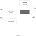
- Figure 20 shows a general schematic of such a system.
- a steerable luminaire 200 may be connected to a manual control system 220 and an automated control system 210, which may itself be connected to a sensing system 230.
- the manual control system allows for dynamic control of illumination effects by an operator, and the automated control system provides for programmed variations in illumination effects and/or dynamic control of illumination effects in response to sensor inputs.
- luminaires are mounted on the exterior of vehicles such as cars or boats.
- the luminaires may be used as steerable spotlight/searchlights.
- these luminaires are thin and flat, enabling them to be mounted into the structure of the vehicle, such as in the door panel or front grill of a car or on the exterior of a boat.
- Figure 21 shows a steerable luminaire 200 mounted in the door of a car 202.
- the system may further comprise a user interface for controlling the direction and spread of the light beam (for example, a pointing joystick) and a microcontroller that controls the luminaire output.
- steerable luminaire panels are mounted on airborne vehicles, such as on the underside of the wings of unmanned aerial vehicles.
- Figure 22 shows steerable luminaires 200 mounted in the wings of an aerial vehicle 203.
- the luminaires so mounted may be used to provide controllable illumination of the ground area beneath the vehicle.
- Use of infrared light sources in such a system will provide controllable infrared illumination of considerable value for night-vision systems.
- the luminaires may be implemented as an emergency light and mounted on emergency vehicles.
- a controller can adjust the luminaire so that it provides a light beam that sweeps from side to side, drawing attention.
- the steerable luminaire may be used to counteract motion and stabilize the pointing of a beam that is emanating from a moving platform such as a boat or truck.
- An active control system would include a sensor such as an accelerometer and a microcontroller that steers the luminaire to counteract movements of the platform on which the luminaire is mounted and keep the output beam targeted on a fixed location.
- a passive inertial system may be used to provide relative motion between the focusing element array and the lightguide, stabilizing the output beam.
- the system performs as a voice-tracking spotlight.
- a steerable luminaire is integrated in a system with a microcontroller and with directional microphones as sensors.
- the signal from the directional microphones is processed by the microntroller to determine the position of a speaking individual and the microcontroller then aims the light beam at that individual.
- Such a system would provide automatic illumination of a speaker. It would be valuable as an automatic spotlight for theatrical use, and as an illumination tool for discussions in conference rooms and other gatherings.
- the system performs as a directional light that automatically tracks an individual.
- the system contains a steerable luminaire, a microcontroller, and one or more sensors used to determine the location of an individual (these can include motion sensors, a camera feed linked to image processing software, acoustic sensors, or other sensor types).
- sensors used to determine the location of an individual (these can include motion sensors, a camera feed linked to image processing software, acoustic sensors, or other sensor types).
- Such a system can be used in many implementations.
- it forms an automatic task light that follows an individual as he or she performs tasks in various locations. This task light can reduce energy usage for lighting by selectively lighting the task areas and reducing the need for high-brightness ambient lighting.
- it forms an automatic intruder spotlight as a component of a security or alarm system.
- the system performs to mimic daylight, providing a natural-feeling light source.
- a steerable luminaire is integrated in a system with a microcontroller and is made to project a beam in a changing angle mimicking the sweep of directional sunlight.
- the system may further include spectral shifts over time to mimic the changing color temperature of sunlight over the course of the day and the year.
- the system is made to augment natural sunlight (for example, from a window or skylight) as it sweeps across a space.
- the light beam from the luminaire is steered to provide "fill" illumination in areas that are insufficiently lit by the daylight beam.
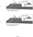
- Figure 23 (a) shows a lightguide 310 lit by a light source 311, with extraction features 313 consisting of two 45° planes and two side planes. For this geometry, the two 45° planes are the primary extraction surfaces.
- Figure 23 (a) shows the alignment of the primary extraction surfaces such that their normal vector has one component parallel to the primary direction of light propagation within the lightguide and the other component in the desired extraction direction.
- Figure 23 (b) shows extraction features 314, which have identical extraction geometry but the normal surface rotated, such that one of the normal vector components is perpendicular to the primary propagation direction.
- Figure 24 shows an alternative construction of extraction features. These are flat features formed by a reflective scattering material, such as white pigment, on one surface of the light guide. Such extraction features are easily formed using painting or printing techniques.
- Figure 24 (b) shows a circular extraction feature 315 made of a circle of scattering material placed on the surface of the light guide.
- Figure 25(a) shows an extraction feature 316 formed using a "halftone" or "dither” technique, in which the area of the extraction feature is filled with smaller areas 317 of scattering material. These may be made of dots or other shapes. The small areas of scattering material fill a portion of the overall area of the extraction feature, and that portion may be adjusted during fabrication by adjusting the pattern in order to change the total amount of light scattered by the extraction feature.
- This technique is to compensate for the changing intensity of light propagation within the lightguide along its length, in order to maintain a more uniform output intensity along the length of the luminaire.
- Figure 25 shows an alternative example of a dithering pattern, in which a circular extraction feature 318 is divided into wedges and a portion 319 of the wedges provided with scattering material. Clocking (rotating) or dithering the pattern amongst several extraction features in a given group, as depicted in Figure 25 , would minimize the perception of any half-toning pattern in the total output beam. Additionally, beam shaping can be achieved through this technique to add more energy to portions of the angular extent of the beam.
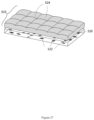
- a customized lightfield luminaire is shown in cross-section in Figure 26 and perspective view in Figure 27 . It is comprised of a lightguide 520 that is lit by light sources 521.
- the lightguide 520 is formed of transparent plastic or glass.
- the lightguide 520 has extraction features 522 on one surface.
- An array 523 of focusing dielectric-filled reflectors 524 is placed on the opposite surface of the lightguide, separated by a small air gap that provides optical cladding.
- the extraction features 522 are located approximately at the focal plane of the reflectors 524.
- the extraction features 522 are preferably formed by scattering pigment such as white paint or ink and may be produced on the surface of the lightguide 520 by any number of processes including inkjet printing, silk screening, pad printing, and similar processes.
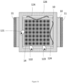
- the area 530 may be thought of as being divided into an array of small pixels, each of which corresponds to a different output beam angle and each of which may optionally contain an extraction feature. Pixels in the center of the area 530 result in beams that exit perpendicular to the plane of the light guide, while pixels offset from the center result in beams that emerge at a corresponding angle.
- the total output of the luminaire is the sum of the beams produced by each reflector in the array 523. Therefore, the total light power at any given beam angle is dependent upon the number of light guide areas 530 in which the corresponding pixel contains an extraction feature.
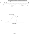
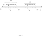
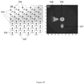
- FIG 28 (a) An example is shown in Figure 28 (a) .
- An array of extraction features are placed in an array of light guide areas 530 associated with a reflector array.
- a large circular center extraction feature 533 is placed in half of the light guide areas
- a triangular extraction feature 534 is in the other half
- a smaller circular extraction feature 535 is in all the light guide areas.
- These three extraction features combine in the projected illuminance pattern, which features a round central beam 536 resulting from the extraction features 533, a smaller high-intensity angled circular beam 537 resulting from the extraction features 535, and an angled triangular wash resulting from the extraction features 534.
- This illumination pattern is shown in Figure 28 (b) , which is an intensity plot of beam power vs angle.
- any arbitrary luminance pattern can be produced. Intensity at each beam angle is controlled by varying the number of light guide areas 530 in which extraction features are placed at the corresponding position.
- a second method of varying beam intensity is to print the extraction features using a half-tone approach, as shown in Figures 24 and 25 .
- the material of the extraction feature is printed in small dots or other shapes dithered to set the amount of extracted light.
- the dither may be applied with a randomized pattern so that it is not visible in the total output beam, which contains the sum of the dithering projected by multiple different reflectors. Further, the pitch of the dither may be made sufficiently small that the dithering is not evident even in the projected beam from a single reflector.
- uniform planar light guide sources for example backlight units
- backlight units for example backlight units
- the same principles can be applied to the patterned lightguide of the custom lightfield design.
- the pixel pattern and/or halftone in each subcell can be adjusted to ensure that the desired extraction feature density and density gradients are achieved, when analyzed on a subcell-by-subcell size scale. Optimization of the patterns may also be carried out to minimize self-shadowing of the output light by the extraction features.
- the reflector array 523 may be made movable rather than fixed. In this case, the position of the reflector array may be adjusted relative to the light guide. Doing so will cause the orientation of the light guide subcells and the reflectors to shift, causing the output beam pattern to be steered. This provides a mechanism for a steerable output beam of arbitrary pattern.
- the reflective lens array may be irregular, containing lenses of varied design. Different lenses may be optimized to project beams at different angles, permitting higher precision in achieving a given light distribution than can be achieved using a uniform lens array.
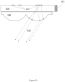
- a refractive lens array in place of a reflective array as shown in Figure 29 .
- a refractive lens array 540 is placed against the lightguide 520 with a small gap for cladding.
- the refractive lenses will produce a different correlation between extraction feature position and output beam angle, but otherwise the design of the luminaire is very similar to the reflective array case.
- a further variation shown in Figure 30 is to use matched arrays of refractive lenses 550 and reflectors 551; this is referred to as a "catadioptric" system. If properly designed, the catadioptric system maintains a flatter focal plane than a single optic system and therefore can enable finer control over the illuminance pattern.
- the extraction features may be made of colored scattering material rather than white scattering material. This will cause light of only the specific color to be directed into the output beam.
- a lightguide that is patterned with extraction features in a variety of colors will project that colored design. This provides a facile mechanism for producing lamps that project colored scenes, images, or logos.
- the extraction features may contain downconverting materials (such as phosphors) that change the wavelength of light as well as scatter it.
- a short wavelength light source can be used, with longer wavelenths produced by the downconverting material in the extraction features.
- different downconverting material compositions may be used in different areas of the patterned lightguide in order to produce a variety of hues in the output pattern.
- the extraction features may be made non-planar.
- the extraction features may be formed as volume features that protrude into the lightguide.
- the luminaire may be designed so that the patterned lightguide is removable and replaceable. This allows the illumination pattern of the luminaire to be changed if desired.
- the lightguide may be made of a fixed component and a removable component, in order to facilitate changes to the illumination pattern. Extraction features are instead printed on a lightguide film which is laminated onto the fixed lightguide.
- the lightguide film may be attached to the fixed lightguide with an optically transparent adhesive.
- the lightguide film may be formed of a "cling" material such as vinyl that naturally adheres to the lightguide.
Landscapes
- Physics & Mathematics (AREA)
- Optics & Photonics (AREA)
- Engineering & Computer Science (AREA)
- General Physics & Mathematics (AREA)
- General Engineering & Computer Science (AREA)
- Microelectronics & Electronic Packaging (AREA)
- Non-Portable Lighting Devices Or Systems Thereof (AREA)
- Fastening Of Light Sources Or Lamp Holders (AREA)
Applications Claiming Priority (6)
| Application Number | Priority Date | Filing Date | Title |
|---|---|---|---|
| US201662399911P | 2016-09-26 | 2016-09-26 | |
| US201762452381P | 2017-01-31 | 2017-01-31 | |
| US201762457819P | 2017-02-11 | 2017-02-11 | |
| US15/715,017 US20180087748A1 (en) | 2016-09-26 | 2017-09-25 | Adjustable-beam luminaires |
| PCT/US2017/053527 WO2018058136A1 (fr) | 2016-09-26 | 2017-09-26 | Luminaires à faisceau réglable |
| EP17781289.8A EP3516439A1 (fr) | 2016-09-26 | 2017-09-26 | Luminaires à faisceau réglable |
Related Parent Applications (1)
| Application Number | Title | Priority Date | Filing Date |
|---|---|---|---|
| EP17781289.8A Division EP3516439A1 (fr) | 2016-09-26 | 2017-09-26 | Luminaires à faisceau réglable |
Publications (2)
| Publication Number | Publication Date |
|---|---|
| EP4530684A2 true EP4530684A2 (fr) | 2025-04-02 |
| EP4530684A3 EP4530684A3 (fr) | 2025-06-18 |
Family
ID=61687766
Family Applications (2)
| Application Number | Title | Priority Date | Filing Date |
|---|---|---|---|
| EP17781289.8A Ceased EP3516439A1 (fr) | 2016-09-26 | 2017-09-26 | Luminaires à faisceau réglable |
| EP25156461.3A Pending EP4530684A3 (fr) | 2016-09-26 | 2017-09-26 | Luminaires à faisceau réglable |
Family Applications Before (1)
| Application Number | Title | Priority Date | Filing Date |
|---|---|---|---|
| EP17781289.8A Ceased EP3516439A1 (fr) | 2016-09-26 | 2017-09-26 | Luminaires à faisceau réglable |
Country Status (4)
| Country | Link |
|---|---|
| US (6) | US20180087748A1 (fr) |
| EP (2) | EP3516439A1 (fr) |
| CN (1) | CN109863440B (fr) |
| WO (1) | WO2018058136A1 (fr) |
Families Citing this family (21)
| Publication number | Priority date | Publication date | Assignee | Title |
|---|---|---|---|---|
| US11585515B2 (en) | 2016-01-28 | 2023-02-21 | Korrus, Inc. | Lighting controller for emulating progression of ambient sunlight |
| US11635188B2 (en) * | 2017-03-27 | 2023-04-25 | Korrus, Inc. | Lighting systems generating visible-light emissions for dynamically emulating sky colors |
| US12385623B2 (en) | 2016-01-28 | 2025-08-12 | Korrus, Inc. | Beam-shaping lighting systems |
| EP3516292B1 (fr) * | 2016-09-22 | 2020-06-17 | Signify Holding B.V. | Agencement optique, système d'éclairage et procédé d'éclairage |
| US10393348B2 (en) | 2017-02-24 | 2019-08-27 | Glint Photonics, Inc. | Configurable luminaire |
| CN207065143U (zh) * | 2017-04-26 | 2018-03-02 | 欧普照明股份有限公司 | 一种发光模组及应用该发光模组的照明装置 |
| US10788188B2 (en) | 2017-11-27 | 2020-09-29 | Glint Photonics, Inc. | Configurable luminaires and components |
| EP3557126B1 (fr) | 2018-04-20 | 2024-03-13 | Insolight SA | Système optomécanique et procédé pour commander la distribution photométrique de luminaires et luminaires correspondants |
| JP6963123B2 (ja) | 2018-05-01 | 2021-11-05 | シグニファイ ホールディング ビー ヴィSignify Holding B.V. | 制御可能な光出力特性を有する照明デバイス |
| US10705289B2 (en) * | 2018-06-14 | 2020-07-07 | Sharp Kabushiki Kaisha | Lighting device and display device |
| US11566786B2 (en) * | 2018-07-26 | 2023-01-31 | Svetlana Tavabilevna GAINANOVA | Facade construction with integrated LED light sources |
| NL2022293B1 (en) * | 2018-12-24 | 2020-07-21 | Schreder Sa | Luminaire system with movable support |
| NL2022294B1 (en) | 2018-12-24 | 2020-07-21 | Schreder Sa | Luminaire system with converted movement |
| NL2022297B1 (en) * | 2018-12-24 | 2020-07-23 | Schreder Sa | Luminaire system with movable modules |
| US10663122B1 (en) * | 2018-12-29 | 2020-05-26 | Self Electronics Co., Ltd. | Line source sweeping light fixture |
| CN110379761B (zh) * | 2019-07-18 | 2021-08-24 | 京东方科技集团股份有限公司 | 微发光二极管转移基板及装置 |
| CN113325579A (zh) | 2020-02-28 | 2021-08-31 | 苏州苏大维格科技集团股份有限公司 | 用于呈现增强现实图像的装置和包含该装置的系统 |
| DE102020109136A1 (de) | 2020-04-02 | 2021-10-07 | Bayerische Motoren Werke Aktiengesellschaft | Beleuchtungsvorrichtung für ein Kraftfahrzeug |
| EP4157245A4 (fr) * | 2020-05-27 | 2024-06-26 | United States Government as Represented by The Department of Veterans Affairs | Résine photodurcissable pour impression 3d à haute résolution |
| DE112021006068T5 (de) * | 2020-11-20 | 2023-10-12 | Korrus, Inc. | Beleuchtungssysteme, die emissionen von sichtbarem licht erzeugen zur dynamischen emulation von himmelsfarben |
| CN113390037A (zh) * | 2021-08-04 | 2021-09-14 | 广州光联电子科技有限公司 | 手动式光源调节装置 |
Family Cites Families (32)
| Publication number | Priority date | Publication date | Assignee | Title |
|---|---|---|---|---|
| GB9406742D0 (en) * | 1994-04-06 | 1994-05-25 | Crossland William A | Thin panel display screen |
| JPH1126813A (ja) * | 1997-06-30 | 1999-01-29 | Toyoda Gosei Co Ltd | 発光ダイオードランプ |
| US6542309B2 (en) * | 2001-06-29 | 2003-04-01 | The Boeing Company | Flexible lens |
| SE527683C2 (sv) * | 2004-05-17 | 2006-05-09 | Curt Edstroem | Belysningsarrangemang |
| US8033706B1 (en) * | 2004-09-09 | 2011-10-11 | Fusion Optix, Inc. | Lightguide comprising a low refractive index region |
| US20090268483A1 (en) * | 2004-11-15 | 2009-10-29 | Donahue Inventions Llc | Illuminable marking device |
| US7680170B2 (en) * | 2006-06-15 | 2010-03-16 | Oclaro Photonics, Inc. | Coupling devices and methods for stacked laser emitter arrays |
| US8040458B2 (en) | 2006-09-26 | 2011-10-18 | Panasonic Corporation | Planar illumination device and liquid crystal display device using the same |
| US20090021816A1 (en) * | 2006-09-27 | 2009-01-22 | Xin Simon Luo | Apparatus and method for laser and optical coupling |
| TW200928186A (en) * | 2007-09-11 | 2009-07-01 | Koninkl Philips Electronics Nv | Illumination system, light source and beam-control element |
| TW200940871A (en) * | 2008-01-08 | 2009-10-01 | Koninkl Philips Electronics Nv | Lighting system |
| US10578789B2 (en) * | 2008-03-03 | 2020-03-03 | Abl Ip Holding, Llc | Optical system and method for managing brightness contrasts between high brightness light sources and surrounding surfaces |
| EP2211089A1 (fr) * | 2009-01-26 | 2010-07-28 | GLP German Light Products GmbH | Appareil et procédé pour la génération d'un faisceau lumineux de couleur mixte |
| US20100265557A1 (en) * | 2009-04-21 | 2010-10-21 | Jesper Sallander | Optical Systems Configured to Generate More Closely Spaced Light Beams and Pattern Generators Including the Same |
| US9256007B2 (en) * | 2009-04-21 | 2016-02-09 | Svv Technology Innovations, Inc. | Light collection and illumination systems employing planar waveguide |
| US8197105B2 (en) * | 2009-08-13 | 2012-06-12 | Intematix Corporation | LED-based lamps |
| CN103314254A (zh) * | 2010-12-02 | 2013-09-18 | 英特曼帝克司公司 | 具有光导及光致发光材料的固态灯 |
| US20130026922A1 (en) * | 2011-07-29 | 2013-01-31 | Osram Sylvania Inc. | Apparatus incorporating an optically transmitting circuit board |
| US8657464B2 (en) * | 2011-11-02 | 2014-02-25 | Honeywell International Inc. | Multiple mode light emitting device |
| US20130215122A1 (en) * | 2012-02-17 | 2013-08-22 | Rambus Inc. | Display apparatus with light guide based solar concentrator |
| US8834004B2 (en) * | 2012-08-13 | 2014-09-16 | 3M Innovative Properties Company | Lighting devices with patterned printing of diffractive extraction features |
| JP6255021B2 (ja) | 2012-09-04 | 2017-12-27 | コーニンクレッカ フィリップス エヌ ヴェKoninklijke Philips N.V. | 光線療法の間に乳幼児を選択的に照射するシステム及び方法 |
| CN110094666A (zh) * | 2012-09-13 | 2019-08-06 | 夸克星有限责任公司 | 提供直接和间接照明的照明系统 |
| US20150260901A1 (en) * | 2012-10-11 | 2015-09-17 | Koninklijke Philips N.V. | Thin and efficient light guide system |
| EP2989375B1 (fr) * | 2013-03-12 | 2019-12-11 | Seoul Semiconductor Co., Ltd. | Luminaire mince |
| US10107951B2 (en) * | 2013-05-24 | 2018-10-23 | 3M Innovative Properties Company | Lightguides having angled light extracting surfaces and specific optical absorption coefficient |
| US10048429B2 (en) * | 2013-09-26 | 2018-08-14 | The Regents Of The University Of California | Illuminator with adjustable beam direction and divergence |
| KR102396551B1 (ko) * | 2013-12-19 | 2022-05-12 | 코닝 인코포레이티드 | 디스플레이 응용을 위한 텍스쳐링된 표면 |
| JP6270674B2 (ja) * | 2014-02-27 | 2018-01-31 | シチズン時計株式会社 | 投影装置 |
| JP6447081B2 (ja) | 2014-12-15 | 2019-01-09 | 日亜化学工業株式会社 | 光源装置及び該光源装置を備えたプロジェクタ |
| CN104819389B (zh) * | 2014-12-23 | 2017-04-26 | 深圳市科曼医疗设备有限公司 | 手术灯和手术灯的光斑调节装置 |
| US10162105B2 (en) * | 2016-03-20 | 2018-12-25 | Robe Lighting S.R.O. | Wash light luminaire with special effects capabilities |
-
2017
- 2017-09-25 US US15/715,017 patent/US20180087748A1/en not_active Abandoned
- 2017-09-26 WO PCT/US2017/053527 patent/WO2018058136A1/fr not_active Ceased
- 2017-09-26 EP EP17781289.8A patent/EP3516439A1/fr not_active Ceased
- 2017-09-26 CN CN201780059457.1A patent/CN109863440B/zh active Active
- 2017-09-26 EP EP25156461.3A patent/EP4530684A3/fr active Pending
-
2019
- 2019-03-14 US US16/353,647 patent/US10837624B2/en active Active
-
2020
- 2020-10-07 US US17/065,357 patent/US11131441B2/en active Active
-
2021
- 2021-09-16 US US17/476,616 patent/US11655965B2/en active Active
-
2023
- 2023-05-04 US US18/143,117 patent/US11879616B2/en active Active
-
2024
- 2024-01-22 US US18/419,022 patent/US20240318807A1/en active Pending
Non-Patent Citations (1)
| Title |
|---|
| WILLIAM M. MELLETTEGLENN M. SCHUSTERJOSEPH E. FORD: "Planar waveguide LED illuminator with controlled directionality and divergence", OPTICS EXPRESS, vol. 22, no. 3, 2014 |
Also Published As
| Publication number | Publication date |
|---|---|
| US20200080707A1 (en) | 2020-03-12 |
| CN109863440B (zh) | 2022-09-02 |
| US20230304647A1 (en) | 2023-09-28 |
| US11131441B2 (en) | 2021-09-28 |
| US20240318807A1 (en) | 2024-09-26 |
| US11655965B2 (en) | 2023-05-23 |
| EP4530684A3 (fr) | 2025-06-18 |
| US11879616B2 (en) | 2024-01-23 |
| US20180087748A1 (en) | 2018-03-29 |
| US20220034483A1 (en) | 2022-02-03 |
| EP3516439A1 (fr) | 2019-07-31 |
| US10837624B2 (en) | 2020-11-17 |
| WO2018058136A1 (fr) | 2018-03-29 |
| US20210095835A1 (en) | 2021-04-01 |
| CN109863440A (zh) | 2019-06-07 |
Similar Documents
| Publication | Publication Date | Title |
|---|---|---|
| US11879616B2 (en) | Adjustable-beam luminaires | |
| US10563844B2 (en) | Configurable luminaire with light sources variably oriented with respect to an array of concave mirrors | |
| KR102536758B1 (ko) | 인공 스카이라이트 및 방법 | |
| CN101688646B (zh) | 具有可调整的光束形状的基于led的照明器 | |
| KR102255641B1 (ko) | 대면적 광원 및 대면적 조명기구 | |
| EP3369985B1 (fr) | Luminaire ayant un guide de lumière | |
| KR102327040B1 (ko) | 광 빔 분포의 픽셀화된 제어를 갖는 고체-상태 조명기구 | |
| EP2478397B1 (fr) | Dispositif photoémetteur | |
| US20120294009A1 (en) | Lighting structure | |
| CN114423992B (zh) | 具有机动化准直控制的照明装置 | |
| WO2018157903A1 (fr) | Source de lumière à grande superficie basée sur la lumière du soleil et luminaire à grande superficie | |
| CN107023782A (zh) | 发光设备 | |
| US20170074476A1 (en) | Optical system for a led luminaire | |
| EP3497365B1 (fr) | Luminaire indirecte | |
| WO2017165685A1 (fr) | Système optique pour luminaire à del | |
| WO2019192280A1 (fr) | Lampe de projection nocturne |
Legal Events
| Date | Code | Title | Description |
|---|---|---|---|
| PUAI | Public reference made under article 153(3) epc to a published international application that has entered the european phase |
Free format text: ORIGINAL CODE: 0009012 |
|
| STAA | Information on the status of an ep patent application or granted ep patent |
Free format text: STATUS: THE APPLICATION HAS BEEN PUBLISHED |
|
| AC | Divisional application: reference to earlier application |
Ref document number: 3516439 Country of ref document: EP Kind code of ref document: P |
|
| AK | Designated contracting states |
Kind code of ref document: A2 Designated state(s): AL AT BE BG CH CY CZ DE DK EE ES FI FR GB GR HR HU IE IS IT LI LT LU LV MC MK MT NL NO PL PT RO RS SE SI SK SM TR |
|
| REG | Reference to a national code |
Ref country code: DE Ref legal event code: R079 Free format text: PREVIOUS MAIN CLASS: G02B0003000000 Ipc: G02B0019000000 |
|
| PUAL | Search report despatched |
Free format text: ORIGINAL CODE: 0009013 |
|
| AK | Designated contracting states |
Kind code of ref document: A3 Designated state(s): AL AT BE BG CH CY CZ DE DK EE ES FI FR GB GR HR HU IE IS IT LI LT LU LV MC MK MT NL NO PL PT RO RS SE SI SK SM TR |
|
| RIC1 | Information provided on ipc code assigned before grant |
Ipc: G02B 3/00 20060101ALN20250514BHEP Ipc: G02B 26/08 20060101ALN20250514BHEP Ipc: F21K 9/61 20160101ALI20250514BHEP Ipc: F21V 8/00 20060101ALI20250514BHEP Ipc: G02B 19/00 20060101AFI20250514BHEP |