EP4530674A2 - Procédé et système radar pour déterminer la position angulaire, l'emplacement et/ou la vitesse, en particulier vectorisée, d'une cible - Google Patents
Procédé et système radar pour déterminer la position angulaire, l'emplacement et/ou la vitesse, en particulier vectorisée, d'une cible Download PDFInfo
- Publication number
- EP4530674A2 EP4530674A2 EP25157553.6A EP25157553A EP4530674A2 EP 4530674 A2 EP4530674 A2 EP 4530674A2 EP 25157553 A EP25157553 A EP 25157553A EP 4530674 A2 EP4530674 A2 EP 4530674A2
- Authority
- EP
- European Patent Office
- Prior art keywords
- signal
- target
- transmitting
- hyp
- radar
- Prior art date
- Legal status (The legal status is an assumption and is not a legal conclusion. Google has not performed a legal analysis and makes no representation as to the accuracy of the status listed.)
- Pending
Links
Images


Classifications
-
- G—PHYSICS
- G01—MEASURING; TESTING
- G01S—RADIO DIRECTION-FINDING; RADIO NAVIGATION; DETERMINING DISTANCE OR VELOCITY BY USE OF RADIO WAVES; LOCATING OR PRESENCE-DETECTING BY USE OF THE REFLECTION OR RERADIATION OF RADIO WAVES; ANALOGOUS ARRANGEMENTS USING OTHER WAVES
- G01S13/00—Systems using the reflection or reradiation of radio waves, e.g. radar systems; Analogous systems using reflection or reradiation of waves whose nature or wavelength is irrelevant or unspecified
- G01S13/02—Systems using reflection of radio waves, e.g. primary radar systems; Analogous systems
- G01S13/50—Systems of measurement based on relative movement of target
- G01S13/58—Velocity or trajectory determination systems; Sense-of-movement determination systems
- G01S13/589—Velocity or trajectory determination systems; Sense-of-movement determination systems measuring the velocity vector
-
- G—PHYSICS
- G01—MEASURING; TESTING
- G01S—RADIO DIRECTION-FINDING; RADIO NAVIGATION; DETERMINING DISTANCE OR VELOCITY BY USE OF RADIO WAVES; LOCATING OR PRESENCE-DETECTING BY USE OF THE REFLECTION OR RERADIATION OF RADIO WAVES; ANALOGOUS ARRANGEMENTS USING OTHER WAVES
- G01S13/00—Systems using the reflection or reradiation of radio waves, e.g. radar systems; Analogous systems using reflection or reradiation of waves whose nature or wavelength is irrelevant or unspecified
- G01S13/003—Bistatic radar systems; Multistatic radar systems
-
- G—PHYSICS
- G01—MEASURING; TESTING
- G01S—RADIO DIRECTION-FINDING; RADIO NAVIGATION; DETERMINING DISTANCE OR VELOCITY BY USE OF RADIO WAVES; LOCATING OR PRESENCE-DETECTING BY USE OF THE REFLECTION OR RERADIATION OF RADIO WAVES; ANALOGOUS ARRANGEMENTS USING OTHER WAVES
- G01S13/00—Systems using the reflection or reradiation of radio waves, e.g. radar systems; Analogous systems using reflection or reradiation of waves whose nature or wavelength is irrelevant or unspecified
- G01S13/02—Systems using reflection of radio waves, e.g. primary radar systems; Analogous systems
- G01S13/06—Systems determining position data of a target
- G01S13/08—Systems for measuring distance only
- G01S13/32—Systems for measuring distance only using transmission of continuous waves, whether amplitude-, frequency-, or phase-modulated, or unmodulated
- G01S13/34—Systems for measuring distance only using transmission of continuous waves, whether amplitude-, frequency-, or phase-modulated, or unmodulated using transmission of continuous, frequency-modulated waves while heterodyning the received signal, or a signal derived therefrom, with a locally-generated signal related to the contemporaneously transmitted signal
-
- G—PHYSICS
- G01—MEASURING; TESTING
- G01S—RADIO DIRECTION-FINDING; RADIO NAVIGATION; DETERMINING DISTANCE OR VELOCITY BY USE OF RADIO WAVES; LOCATING OR PRESENCE-DETECTING BY USE OF THE REFLECTION OR RERADIATION OF RADIO WAVES; ANALOGOUS ARRANGEMENTS USING OTHER WAVES
- G01S13/00—Systems using the reflection or reradiation of radio waves, e.g. radar systems; Analogous systems using reflection or reradiation of waves whose nature or wavelength is irrelevant or unspecified
- G01S13/02—Systems using reflection of radio waves, e.g. primary radar systems; Analogous systems
- G01S13/06—Systems determining position data of a target
- G01S13/42—Simultaneous measurement of distance and other co-ordinates
-
- G—PHYSICS
- G01—MEASURING; TESTING
- G01S—RADIO DIRECTION-FINDING; RADIO NAVIGATION; DETERMINING DISTANCE OR VELOCITY BY USE OF RADIO WAVES; LOCATING OR PRESENCE-DETECTING BY USE OF THE REFLECTION OR RERADIATION OF RADIO WAVES; ANALOGOUS ARRANGEMENTS USING OTHER WAVES
- G01S13/00—Systems using the reflection or reradiation of radio waves, e.g. radar systems; Analogous systems using reflection or reradiation of waves whose nature or wavelength is irrelevant or unspecified
- G01S13/02—Systems using reflection of radio waves, e.g. primary radar systems; Analogous systems
- G01S13/50—Systems of measurement based on relative movement of target
- G01S13/58—Velocity or trajectory determination systems; Sense-of-movement determination systems
- G01S13/583—Velocity or trajectory determination systems; Sense-of-movement determination systems using transmission of continuous unmodulated waves, amplitude-, frequency-, or phase-modulated waves and based upon the Doppler effect resulting from movement of targets
- G01S13/584—Velocity or trajectory determination systems; Sense-of-movement determination systems using transmission of continuous unmodulated waves, amplitude-, frequency-, or phase-modulated waves and based upon the Doppler effect resulting from movement of targets adapted for simultaneous range and velocity measurements
-
- G—PHYSICS
- G01—MEASURING; TESTING
- G01S—RADIO DIRECTION-FINDING; RADIO NAVIGATION; DETERMINING DISTANCE OR VELOCITY BY USE OF RADIO WAVES; LOCATING OR PRESENCE-DETECTING BY USE OF THE REFLECTION OR RERADIATION OF RADIO WAVES; ANALOGOUS ARRANGEMENTS USING OTHER WAVES
- G01S13/00—Systems using the reflection or reradiation of radio waves, e.g. radar systems; Analogous systems using reflection or reradiation of waves whose nature or wavelength is irrelevant or unspecified
- G01S13/87—Combinations of radar systems, e.g. primary radar and secondary radar
- G01S13/878—Combination of several spaced transmitters or receivers of known location for determining the position of a transponder or a reflector
-
- G—PHYSICS
- G01—MEASURING; TESTING
- G01S—RADIO DIRECTION-FINDING; RADIO NAVIGATION; DETERMINING DISTANCE OR VELOCITY BY USE OF RADIO WAVES; LOCATING OR PRESENCE-DETECTING BY USE OF THE REFLECTION OR RERADIATION OF RADIO WAVES; ANALOGOUS ARRANGEMENTS USING OTHER WAVES
- G01S7/00—Details of systems according to groups G01S13/00, G01S15/00, G01S17/00
- G01S7/02—Details of systems according to groups G01S13/00, G01S15/00, G01S17/00 of systems according to group G01S13/00
- G01S7/35—Details of non-pulse systems
- G01S7/352—Receivers
-
- G—PHYSICS
- G01—MEASURING; TESTING
- G01S—RADIO DIRECTION-FINDING; RADIO NAVIGATION; DETERMINING DISTANCE OR VELOCITY BY USE OF RADIO WAVES; LOCATING OR PRESENCE-DETECTING BY USE OF THE REFLECTION OR RERADIATION OF RADIO WAVES; ANALOGOUS ARRANGEMENTS USING OTHER WAVES
- G01S13/00—Systems using the reflection or reradiation of radio waves, e.g. radar systems; Analogous systems using reflection or reradiation of waves whose nature or wavelength is irrelevant or unspecified
- G01S13/88—Radar or analogous systems specially adapted for specific applications
- G01S13/93—Radar or analogous systems specially adapted for specific applications for anti-collision purposes
- G01S13/931—Radar or analogous systems specially adapted for specific applications for anti-collision purposes of land vehicles
- G01S2013/9327—Sensor installation details
- G01S2013/93271—Sensor installation details in the front of the vehicles
-
- G—PHYSICS
- G01—MEASURING; TESTING
- G01S—RADIO DIRECTION-FINDING; RADIO NAVIGATION; DETERMINING DISTANCE OR VELOCITY BY USE OF RADIO WAVES; LOCATING OR PRESENCE-DETECTING BY USE OF THE REFLECTION OR RERADIATION OF RADIO WAVES; ANALOGOUS ARRANGEMENTS USING OTHER WAVES
- G01S7/00—Details of systems according to groups G01S13/00, G01S15/00, G01S17/00
- G01S7/02—Details of systems according to groups G01S13/00, G01S15/00, G01S17/00 of systems according to group G01S13/00
- G01S7/35—Details of non-pulse systems
- G01S7/352—Receivers
- G01S7/356—Receivers involving particularities of FFT processing
Definitions
- the present invention relates to a radar method and system for determining the angular position, the location and/or the, in particular vectorial, speed of a target.
- Known radar methods particularly for estimating vector velocity (cf. [1]-[3]), use distributed radar devices that individually and independently measure a Doppler velocity relative to an object (target).
- the Doppler velocity can be interpreted as the projection of the vector velocity onto a connecting vector between the radar and the target. If the positions of the radars and the target are known or can be determined, the vector velocity can be determined from the individual projections by solving a system of linear equations.
- the accuracy of this method is highly dependent on the geometric distribution of the stations relative to the target ("dilution of precision").
- the object of the invention is to determine an angular position, a location and/or a, in particular vectorial, speed of a target with comparatively high accuracy in the simplest possible manner.
- the problem is solved by a radar method for determining the angular position, location, and/or, in particular, vectorial, velocity of a target.
- a first transceiver unit and at least one second transceiver unit are not synchronized, but the start of measurement of the first transceiver unit and the second transceiver unit is triggered (wirelessly or wired) with a temporal deviation (trigger offset time) ⁇ t n .
- measurements of the transceiver units are processed coherently.
- the second transmitting/receiving unit shall be considered non-synchronized with the first transmitting/receiving unit, in particular, if a temporal deviation (trigger offset time) between the first and second transmitting/receiving units is greater than 1 ps, preferably greater than 1 ns, possibly greater than 10 ns.
- the temporal deviation ⁇ t n may be ⁇ 10 ⁇ s, preferably ⁇ 1 ⁇ s (especially for a dynamic target). Especially for a stationary target, the temporal deviation may be greater.
- Coherent processing means in particular, that the measurements from the transmit/receive units are further processed as if they were generated by a common local oscillator. An example of this would be two receive antennas of a SIMO radar.
- the present invention enables a simple and accurate estimation (determination) of the vectorial velocity even at an azimuth ⁇ 0° and/or in the near field. Furthermore, the use of coarsely synchronized distributed radar stations to generate large apertures is possible.
- a temporal deviation (trigger offset time) ⁇ t n is understood to mean, in particular, a deviation that arises due to the process or system, in particular due to wireless and/or wired transmissions used.
- the temporal deviation ⁇ t n is therefore particularly inherent to the process or system.
- the measurements (or transmission signals) of the transmitting/receiving units are not generated by a common local oscillator.
- complex conjugate multiplication can correspond to division by a complex phasor with normalized amplitude.
- Holographic processing preferably occurs in the xy direction.
- Interference preferably occurs along a Doppler direction, e.g., by multiplication in the time domain (alternative a)) or by convolution in the frequency domain (alternative b)).
- Holography can be provided in both a) and b) as the basis for the interference.
- At least two signals can be holographically interfered, first spatially, for example in a Cartesian x,y coordinate system, and then in the Doppler plane (velocity plane) by multiplication in the time domain (alternative a), in particular by conjugate complex multiplication, or by convolution in the frequency domain (alternative b).
- a vectorial velocity of the target is determined from a resulting signal.
- the method is particularly preferably configured such that a (2D or 3D) vector velocity of the target can be determined.
- the respective (first and/or second) transmitting-receiving unit determines its own (vector) speed(s) based on a known or determined (vector) speed of one or more (e.g., static) target(s) ( ego-motion estimation ).
- the target can be located in the near field.
- the target can also be located in the far field.
- Near field is preferably understood to mean a distance to the target that is less than or equal to 10 times the distance between the two transmit/receive units (or, in the case of multiple transmit/receive units, the distance between the two transmit/receive units that are furthest apart), or less than or equal to 10 times the aperture size of a system of transmit/receive units.
- a far field is then understood to mean, in particular, a distance to the target that is greater than the relative values just mentioned.
- the target is particularly preferably located in the near field. In contrast to the prior art, precise measurements can be achieved easily in the near field.
- the transmit/receive units form a distributed aperture.
- the distance between multiple transmit/receive units can be at least 20 cm, more preferably at least 50 cm, more preferably at least 100 cm (in the case of multiple transmit/receive units, this can apply either to the distance to the nearest transmit/receive unit or, alternatively, to the distance between the two transmit/receive units that are the largest apart among all pairs of possible transmit/receive units).
- the target is preferably located using a holographic principle.
- the method is an FMCW radar method (where FMCW stands for frequency modulated continuous wave).
- the method works according to the range Doppler principle.
- the at least two transmit/receive units are monostatic.
- a Fourier transformation is performed along a slow time scale.
- Slow time is defined in more detail below.
- a peak search can be performed to determine an ellipse/hyperbolic velocity, particularly in several or all pixels (of the target).
- a determination of ellipse/hyperbolic parameters can be performed, particularly in several or all pixels (of the target).
- a transformation of an ellipse/hyperbolic velocity into a (Cartesian) vector velocity can be performed.
- a signal frequency can be halved before interference occurs.
- a Doppler velocity can be determined, in particular to at least partially compensate for a Doppler shift.
- An optimal filter approach can be used, in particular to at least partially compensate for a Doppler shift and/or when the radar bandwidth is comparatively high and/or the target speed is comparatively high.
- Range Doppler compression can be performed using a fractional Fourier transform (FRFT), especially in the case of a comparatively high bandwidth of the radar and/or a comparatively high speed of the target.
- FRFT fractional Fourier transform
- One or more of the (range-Doppler) compressed signals can be additionally compressed in the azimuth direction, preferably by means of Fourier transformation and/or digital beamforming algorithms, in particular for sidelobe suppression.
- methods are proposed wherein at least three transceiver units are used, wherein a 3D velocity determination is preferably performed, in particular by forming an intersection of two pairs, each consisting of an ellipsoid and a hyperboloid.
- a 3D velocity determination is preferably performed, in particular by forming an intersection of two pairs, each consisting of an ellipsoid and a hyperboloid.
- an optimal filter approach can be used, wherein a hypothesis(es) is/are formed for several or all [ xy, z, v x , v y , v z ] combinations in a search area and compared with measured data.
- a radar system for determining the angular position, the location and/or the, in particular vectorial, speed of a target, in particular for carrying out the above method, wherein a first transmitting-receiving unit and at least one second transmitting-receiving unit are provided, which are not synchronized with one another, wherein a control device is provided which is configured to wirelessly or wiredly determine a start of measurement of the first transmitting-receiving unit and the second transmitting-receiving unit with a time deviation (trigger offset time) ⁇ t n trigger, wherein a computing and/or evaluation device is provided which is configured such that measurements of the transmitting-receiving units are processed coherently.
- this also includes a physically independent evaluation device connected to one or more transceiver units.
- a control device e.g., for triggering the start of a measurement, can also be designed as a physically independent control device (possibly in a common assembly, in particular a housing, with the evaluation device) connected to one or more transceiver units.
- the respective transceiver unit can be designed as an arrangement comprising, in particular, one or more antennas with a few signal-generating or signal-processing components, while other components, such as signal comparison units or a control and/or evaluation device, can be connected to such an arrangement as structurally independent components. If components are used, these can (as far as technically feasible) be designed as so-called hardware consisting of processing components and/or implemented as signals or data processing steps executed entirely or partially in a processor.
- control and/or evaluation device can be a component of one or more transceiver units, or can be connected to one or more such transceiver units. If necessary, a physically independent control and/or evaluation device can be provided, which is connected to the respective transceiver unit or the other components of the respective transceiver unit. Alternatively, the control and/or evaluation device can be integrated into the first and/or second (generally additional) transceiver units, for example, in a common housing and/or as a structural unit.
- Each transceiver unit can have one or more transmitting or receiving antennas.
- the above-mentioned object is further achieved by the use of the method of the above type and/or the system of the above type for a mobile device, preferably a vehicle, in particular a passenger car and/or a truck.
- a mobile device in particular a vehicle, preferably a passenger car and/or a truck, comprising the above system.
- the resulting signal phase in (5) depends only on the distance to the target, the relative radial velocity of the target, and the reflection phase of the target.
- the unknown initial phase ⁇ 0 vanishes during the mixing process in (3).
- the following signal model results for the baseband signal phase in radar number n: ⁇ n t f t i ⁇ 2 ⁇ c f 0 + ⁇ f n d rt , 0 , n + ⁇ d rt , 0 , n + 2 f o + ⁇ f n v r , n t f + ⁇ t n + 2 f o + ⁇ f n v r , n t i + ⁇ t n + ⁇ t t .
- the trigger offset time is ⁇ t n ⁇ 15 ns (possibly 1 to 100 ns, in particular 5 to 30 ns) for wired and ⁇ t n ⁇ 1 ⁇ s (possibly 0.1 to 10 ⁇ s, in particular 0.5 to 2 ⁇ s) for wireless triggering, in general
- ⁇ ⁇ ,n therefore only depends on the distance between the respective radar and the target and can be processed coherently at all stations.
- the radars form a distributed aperture.
- p Tx,n or p Rx,n is the known 2D position of the Tx antenna or Rx antenna of radar n.
- Each radar (transceiver unit) can have one or more Tx or Rx antennas. If more than one antenna is present, a hypothesis must be created for each Tx-Rx combination according to the same principle.
- p t,hyp is a hypothesis to be tested for the 2D position of the target. The procedure can be directly adapted to 3D if the coordinates in (9) are replaced by 3D coordinates.
- (10) reduces to the beamforming approach and the 2D search over x and y can be replaced by a 1D search for the distance and a subsequent search for the angle.
- a 2D search according to (10) is preferably performed. Since the target may be located in different range bins in the individual radars ("range migration"), interpolation in the range direction may be necessary, which can be implemented as a complex-valued linear interpolation.
- This method allows for the coherent processing of non-synchronized distributed radar stations, enabling the realization of large apertures. This enables target localization with high accuracy.
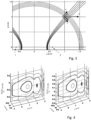
- Fig. 1 shows two transmitting-receiving units 1,2 at a distance of b l from each other, which measure approximately simultaneously according to the FMCW Range Doppler principle to the target, which moves with a vectorial velocity v.
- the geometry can be configured as shown in Fig. 1
- the target is initially located at [ d 0 , ⁇ 0 ] in the radar polar coordinate system and moves with the vector velocity v.
- the corresponding signal model in the transmit-receive units 1, 2, which operate according to the FMCW range-Doppler principle, after range compression e.g.
- * denotes the complex conjugation.
- the interference analogue (14) can also be applied to range-Doppler compressed data.
- the multiplication in (14) must then be replaced by a convolution.
- the complete velocity vector can be determined. This requires knowledge of the angle to the target ⁇ 0. This can be determined, for example, using known angle estimation techniques (beamforming).
- Both resolution and unambiguousness depend on the distance and angle to the target. Increasing the aperture b l leads to an improvement in resolution and a reduction in unambiguousness. Adding additional receiver units between the two existing receivers leads to an increase in unambiguousness.
- At least two roughly synchronized radar units are required.
- the distance between the units is b l (see Fig. 2; Fig. 2 shows two transmitting/receiving units at a distance of b l from each other, which measure the target approximately simultaneously according to the FMCW Range-Doppler principle.
- Both radar units are quasi-monostatic (respective distance between Rx and Tx ⁇ b l ).
- d 0 For the distance to the target d 0 , d 0 » b l does not necessarily hold, ie the target can be in the near field.
- p Tx,n / p Rx,n is the 2D position of the Tx / Rx antenna of radar unit n.
- p t is the 2D position of the target.
- Fig. 1 shows a representation of the movement of a target in the near field of a 2-radar unit arrangement as movement along ellipses/hyperbolas. From the geometry in Fig. 3 It can be seen that the position of the target can be determined by the intersection of an ellipse and a hyperbola with both radars at their focal points.
- intersection point of the ellipse with the hyperbola [ x 0 , y 0 ] is (strictly speaking, there are two intersection points; one of them can easily be selected by plausibility considerations - the other is behind the radar units)
- x 0 ⁇ a E a H c HE
- y 0 ⁇ c HE 4 + a H 2 + a E 2 c HE 2 ⁇ a E 2 a H 2 c HE
- the target movement can therefore be interpreted as a movement a E ( t i ) from ellipse to ellipse along a hyperbola corresponding to a radial velocity and as a movement a H ( t i ) perpendicular to it from hyperbola to hyperbola along an ellipse corresponding to a tangential velocity (cf. Fig. 3 ).
- Fig. 4 shows a resulting 3D spectrum for estimating the tangential/radial velocity at given x and y . Both spectra have the same shape but are located at different locations along the z-axis.
- phase addition in (29) leads to a doubling of the measured Doppler frequency, which results in a halving of the unambiguous measurement range. This can preferably be avoided by halving the signal frequency before interference formation.
- the Doppler shift can preferably be compensated by determining the Doppler velocity for each target and thus correcting the distance.
- an optimal filter approach similar to [12] can be pursued.
- the algorithms presented in this invention can then preferably be applied unchanged to the result.
- FFT-based Doppler compression may no longer be applicable because the distance to the target changes noticeably from ramp to ramp during the burst.
- range Doppler compression can be performed using the fractional Fourier transform (FRFT).
- FRFT fractional Fourier transform
- a range-Doppler-compressed signal can be further compressed in the azimuth direction using a Fourier transform or digital beamforming algorithms (Bartlett, Capon, MUSIC, etc.).
- the presented method can then be applied unchanged to the result. This leads to suppression of the sidelobes in the resulting [ x , y , v x , v y ] image.
- targets can be separated by amplitude, since the signal originating from one target has the same amplitude A 12 in both spectra, but different frequency and phase (cf. equations (30) and (31) and Fig. 4 If two or more targets with the same amplitude are present in a spatial resolution cell, target separation can be achieved using a subsequent tracking algorithm.
- 3D vector velocity estimation of a target is possible using at least three spatially positioned radar units (transceivers). The result is then obtained by intersecting two pairs, each consisting of an ellipsoid and a hyperboloid.
- the method can be generalized to any number of transmit-receive units and radar arrays, especially if an optimal filter is used instead of the Fourier transform processing.
- a hypothesis is formed for each [ x, y , z , v x , v y , v z ] combination in the search area and compared with the measured data.
- ⁇ denotes the scalar product of two vectors.
- the target position and vector velocity can be determined by maximum search in the resulting 4D pseudospectrum. For 3D problems, a 6D spectrum can be obtained using an analogous procedure.
- This method may be more computationally intensive than the FFT-based method presented previously.
- the procedure can therefore be applied unchanged to a combination of a direct path and a cross path. This has the advantage that goals that are visible in the cross path and in one direct path, but not in both direct paths.
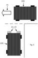
- Fig. 5 shows an automotive application with a car (20) equipped with two radars (1), (2) that are triggered approximately simultaneously by a signal. Another car (30) is driving in the direction of the arrow (4).
- the car (20) can, for example, be waiting at an intersection or approaching the intersection.
- the distance and angle to the car (30) can be determined.
- the relative radial velocity can be determined. Since in this case the car (30) is moving approximately tangentially to the connecting axis between radar (1), (2) and target, i.e. car (30), the Doppler frequency would be ⁇ 0 Hz. The measured radial velocity would therefore be ⁇ 0 m/s. It is therefore not possible to determine whether the car (30) is moving or stationary.
- the signals from the radar stations (1), (2) can be coherently processed, even though they are not (phase) synchronized, and from this the (complete) vectorial velocity of the car (30) can be determined.
- This information can be fused with other algorithms for environment detection, which is advantageous for driver assistance systems and autonomous driving.
- each point in the radar image can be assigned an amplitude (power), a speed, and a direction of movement.
- Fig. 6 shows another application with a car (20) equipped with two radars (1), (2) that are triggered approximately simultaneously by a signal, with the car driving in the direction of arrow (4).
- Parked cars (30) are present at the side of the road.
- a pedestrian (5) walks onto the road in the direction of arrow (6).
- the present invention also encompasses, in particular, a particularly accurate estimation of the (2D or 3D) vectorial velocity of objects (targets).
- at least two (spatially separated) FMCW radars can be provided, which measure in particular according to the range Doppler principle. These FMCW radars are preferably only roughly time-synchronized. Both stations can be triggered (approximately) simultaneously and transmit and receive FMCW bursts (with a known frequency offset from each other). The complete vectorial velocity of the objects (targets) in the environment can then be estimated from an interference of resulting (baseband) signals.
Landscapes
- Engineering & Computer Science (AREA)
- Radar, Positioning & Navigation (AREA)
- Remote Sensing (AREA)
- Physics & Mathematics (AREA)
- Computer Networks & Wireless Communication (AREA)
- General Physics & Mathematics (AREA)
- Electromagnetism (AREA)
- Radar Systems Or Details Thereof (AREA)
Applications Claiming Priority (3)
| Application Number | Priority Date | Filing Date | Title |
|---|---|---|---|
| DE102017123636 | 2017-10-11 | ||
| DE102018100632.2A DE102018100632A1 (de) | 2017-10-11 | 2018-01-12 | Radar-Verfahren und -System zur Bestimmung der Winkellage, des Ortes und/oder der, insbesondere vektoriellen, Geschwindigkeit eines Zieles |
| EP18199876.6A EP3470874B1 (fr) | 2017-10-11 | 2018-10-11 | Procédé et système radar permettant de déterminer la position angulaire, l'emplacement et la vitesse vectorielle d'une cible |
Related Parent Applications (2)
| Application Number | Title | Priority Date | Filing Date |
|---|---|---|---|
| EP18199876.6A Division EP3470874B1 (fr) | 2017-10-11 | 2018-10-11 | Procédé et système radar permettant de déterminer la position angulaire, l'emplacement et la vitesse vectorielle d'une cible |
| EP18199876.6A Division-Into EP3470874B1 (fr) | 2017-10-11 | 2018-10-11 | Procédé et système radar permettant de déterminer la position angulaire, l'emplacement et la vitesse vectorielle d'une cible |
Publications (2)
| Publication Number | Publication Date |
|---|---|
| EP4530674A2 true EP4530674A2 (fr) | 2025-04-02 |
| EP4530674A3 EP4530674A3 (fr) | 2025-06-04 |
Family
ID=65817015
Family Applications (1)
| Application Number | Title | Priority Date | Filing Date |
|---|---|---|---|
| EP25157553.6A Pending EP4530674A3 (fr) | 2017-10-11 | 2018-10-11 | Procédé et système radar pour déterminer la position angulaire, l'emplacement et/ou la vitesse, en particulier vectorisée, d'une cible |
Country Status (5)
| Country | Link |
|---|---|
| US (1) | US11009598B2 (fr) |
| EP (1) | EP4530674A3 (fr) |
| JP (1) | JP7221640B2 (fr) |
| CN (1) | CN109655821B (fr) |
| DE (1) | DE102018100632A1 (fr) |
Families Citing this family (18)
| Publication number | Priority date | Publication date | Assignee | Title |
|---|---|---|---|---|
| DE102018202293A1 (de) * | 2018-02-15 | 2019-08-22 | Robert Bosch Gmbh | Schätzung von Quergeschwindigkeiten oder kartesischen Geschwindigkeiten von Punktzielen mit einem Radarsensor |
| DE102018202294A1 (de) * | 2018-02-15 | 2019-08-22 | Robert Bosch Gmbh | Schätzung von kartesischen Geschwindigkeiten von ausgedehnten Radarobjekten mit einem Radarsensor |
| CN112534298A (zh) * | 2018-08-07 | 2021-03-19 | 株式会社村田制作所 | 雷达装置 |
| DE102019216152A1 (de) * | 2019-10-21 | 2021-04-22 | Zf Friedrichshafen Ag | Adaptiver Hochpunkt-Nachbarschaftsbereich |
| WO2021089133A1 (fr) * | 2019-11-06 | 2021-05-14 | Huawei Technologies Co., Ltd. | Dispositif et procédé d'estimation de vecteur de vitesse de cible |
| DE102019218932B3 (de) * | 2019-12-05 | 2021-05-06 | Zf Friedrichshafen Ag | Ermitteln einer Relativbewegung |
| DE102020107222A1 (de) * | 2020-03-17 | 2021-09-23 | HELLA GmbH & Co. KGaA | Verfahren zur Bestimmung einer Richtungsinformation |
| IL273814B2 (en) * | 2020-04-05 | 2025-05-01 | Israel Aerospace Ind Ltd | Distributed radar system and method of operation thereof |
| CN111965641B (zh) * | 2020-07-08 | 2022-02-15 | 江苏警官学院 | 一种基于分数阶Fourier变换的SAR成像方法 |
| DE102020123293A1 (de) | 2020-09-07 | 2022-03-10 | Friedrich-Alexander-Universität Erlangen-Nürnberg | Verfahren, Radarsystem und Fahrzeug zur Signalverarbeitung von Radarsignalen |
| WO2022053181A1 (fr) | 2020-09-08 | 2022-03-17 | Friedrich Alexander Universität Erlangen | Mesure de vitesse d'un véhicule à l'aide de multiples radars embarqués |
| EP4036601A1 (fr) * | 2021-01-29 | 2022-08-03 | Aptiv Technologies Limited | Traitement de données radar pour l'estimation d'un ego-mouvement d'un véhicule |
| US11828863B2 (en) * | 2021-03-10 | 2023-11-28 | Qualcomm Incorporated | Timing synchronization for cooperative radar sensing |
| WO2022243152A1 (fr) * | 2021-05-21 | 2022-11-24 | Signify Holding B.V. | Dispositif de commande de reconfiguration d'un système de détection à base de radiofréquence et son procédé |
| KR102704934B1 (ko) * | 2021-11-29 | 2024-09-09 | 엘아이지넥스원 주식회사 | 동기 오차를 보정하는 바이스태틱 레이다 시스템 및 방법 |
| CN114966683B (zh) * | 2022-05-18 | 2025-07-15 | 北方工业大学 | 地基合成孔径雷达动目标成像方法及装置 |
| EP4386428A1 (fr) * | 2022-12-16 | 2024-06-19 | Aptiv Technologies Limited | Détermination de la vitesse radiale d'objets dans des environnements de véhicules |
| US12474437B2 (en) * | 2022-12-22 | 2025-11-18 | Nxp B.V. | Fine frequency offset estimation for coherent distributed radar |
Citations (3)
| Publication number | Priority date | Publication date | Assignee | Title |
|---|---|---|---|---|
| US6982668B1 (en) | 2003-09-30 | 2006-01-03 | Sandia Corporation | Tangential velocity measurement using interferometric MTI radar |
| DE102014104273A1 (de) | 2014-03-26 | 2015-10-01 | Friedrich-Alexander-Universität Erlangen-Nürnberg | Verfahren in einem Radarsystem, Radarsystem bzw. Vorrichtung eines Radarsystems |
| WO2017118621A1 (fr) | 2016-01-04 | 2017-07-13 | Symeo Gmbh | Procédé et système permettant de réduire les parasites dus au bruit de phase dans un système radar |
Family Cites Families (30)
| Publication number | Priority date | Publication date | Assignee | Title |
|---|---|---|---|---|
| US3795911A (en) * | 1961-02-02 | 1974-03-05 | C Hammack | Method and apparatus for automatically determining position-motion state of a moving object |
| US3264644A (en) * | 1962-12-31 | 1966-08-02 | Trw Inc | Unambiguous range radar system |
| US3290677A (en) * | 1962-12-31 | 1966-12-06 | Trw Inc | Continuous wave angle and range determining radar |
| FR2343258A1 (fr) * | 1976-07-01 | 1977-09-30 | Trt Telecom Radio Electr | Systeme radioelectrique de localisation d'un objet determine |
| US4347513A (en) * | 1979-06-08 | 1982-08-31 | The United States Of America As Represented By The Secretary Of The Air Force | Netted search radar system |
| IT1123407B (it) * | 1979-10-02 | 1986-04-30 | Face Standard Ind | Impianto di misura di distanza per aeronavigazione di prescisione |
| US5867489A (en) * | 1996-05-29 | 1999-02-02 | Lockheed Martin Corp. | Method and apparatus for TDMA slot synchronization with precision ranging |
| GB2315943A (en) * | 1996-08-01 | 1998-02-11 | Paul Michael Wood | Distance measuring system |
| US20030071751A1 (en) * | 2001-07-26 | 2003-04-17 | Barrick Donald E. | Ocean surface current mapping with bistatic HF radar |
| US6724340B1 (en) * | 2003-02-13 | 2004-04-20 | Information Systems Laboratories | Detecting system having a coherent sparse aperture |
| DE102005000732A1 (de) * | 2005-01-04 | 2006-07-13 | Siemens Ag | Funkbasiertes Ortungssystem mit synthetischer Apertur |
| DE102005063417B4 (de) * | 2005-12-23 | 2021-01-07 | Airbus Defence and Space GmbH | Antenne für eine hochauflösende Synthetik-Apertur-Radarvorrichtung |
| US7884754B1 (en) * | 2006-04-28 | 2011-02-08 | The United States Of America As Represented By The Secretary Of The Navy | Method of distributed estimation using multiple asynchronous sensors |
| US8711038B2 (en) * | 2006-10-05 | 2014-04-29 | Her Majesty The Queen In Right Of Canada As Represented By The Minister Of Industry, Through The Communications Research Centre Canada | High-resolution ranging and location finding using multicarrier signals |
| JP5197138B2 (ja) * | 2008-04-30 | 2013-05-15 | 三菱電機株式会社 | マルチスタティックレーダ装置 |
| US8184038B2 (en) * | 2008-08-20 | 2012-05-22 | Qualcomm Incorporated | Two-way ranging with inter-pulse transmission and reception |
| CN101738606B (zh) * | 2008-11-21 | 2011-12-28 | 清华大学 | 基于广义多普勒滤波器组的雷达目标相参积累检测方法 |
| DE102009060593A1 (de) * | 2008-12-30 | 2010-07-08 | Atmel Automotive Gmbh | System, Verfahren und Schaltung zur Entfernungsmessung zwischen zwei Knoten eines Funknetzes |
| US8274426B2 (en) * | 2009-04-30 | 2012-09-25 | Greina Technologies, Inc | High-resolution, active reflector radio frequency ranging system |
| DE102009030076A1 (de) * | 2009-06-23 | 2010-12-30 | Symeo Gmbh | Abbildungsverfahren mittels synthetischer Apertur, Verfahren zur Bestimmung einer Relativgeschwindigkeit zwischen einem wellenbasierten Sensor und einem Objekt bzw. Vorrichtung zur Durchführung der Verfahren |
| JP5721578B2 (ja) * | 2011-07-22 | 2015-05-20 | 三菱電機株式会社 | レーダ装置 |
| EP2602636A1 (fr) * | 2011-12-08 | 2013-06-12 | Nederlandse Organisatie voor toegepast -natuurwetenschappelijk onderzoek TNO | Procédé permettant de déterminer la distance et la vitesse de terminaux radar FMCW |
| CN103675816B (zh) * | 2013-11-20 | 2016-01-20 | 中国科学院电子学研究所 | 一种基于压缩感知理论的干涉逆合成孔径雷达成像方法 |
| CN103777188B (zh) * | 2014-01-21 | 2015-11-04 | 中国空间技术研究院 | 一种基于双频共轭处理的InISAR成像方法 |
| JP6365251B2 (ja) * | 2014-02-28 | 2018-08-01 | パナソニック株式会社 | レーダ装置 |
| CN103901425B (zh) * | 2014-04-23 | 2017-08-11 | 武汉大学 | 一种测量运动物体横向速度的雷达及方法 |
| JP6352837B2 (ja) * | 2015-03-02 | 2018-07-04 | 株式会社東芝 | レーダシステム及びそのレーダ信号処理方法 |
| US10641881B2 (en) * | 2015-08-28 | 2020-05-05 | Aptiv Technologies Limited | Bi-static radar system |
| CN106019274B (zh) * | 2016-05-24 | 2019-01-22 | 西安深穹光电科技有限公司 | 一种新型多普勒雷达成像装置及方法 |
| CN106443671A (zh) * | 2016-08-30 | 2017-02-22 | 西安电子科技大学 | 基于调频连续波的sar雷达动目标检测与成像方法 |
-
2018
- 2018-01-12 DE DE102018100632.2A patent/DE102018100632A1/de active Pending
- 2018-10-10 JP JP2018191671A patent/JP7221640B2/ja active Active
- 2018-10-10 US US16/156,474 patent/US11009598B2/en active Active
- 2018-10-11 CN CN201811182616.XA patent/CN109655821B/zh active Active
- 2018-10-11 EP EP25157553.6A patent/EP4530674A3/fr active Pending
Patent Citations (3)
| Publication number | Priority date | Publication date | Assignee | Title |
|---|---|---|---|---|
| US6982668B1 (en) | 2003-09-30 | 2006-01-03 | Sandia Corporation | Tangential velocity measurement using interferometric MTI radar |
| DE102014104273A1 (de) | 2014-03-26 | 2015-10-01 | Friedrich-Alexander-Universität Erlangen-Nürnberg | Verfahren in einem Radarsystem, Radarsystem bzw. Vorrichtung eines Radarsystems |
| WO2017118621A1 (fr) | 2016-01-04 | 2017-07-13 | Symeo Gmbh | Procédé et système permettant de réduire les parasites dus au bruit de phase dans un système radar |
Non-Patent Citations (10)
| Title |
|---|
| A. W. DOERRY: "Patch diameter limitation due to high chirp rates in focused SAR images", IEEE TRANSACTIONS ON AEROSPACE AND ELECTRONIC SYSTEMS, vol. 30, no. 4, 1994, pages 1125 - 1129 |
| D. KELLNERM. BARJENBRUCHK. DIETMAYERJ. KLAPPSTEINJ. DICKMANN: "Instantaneous lateral velocity estimation of a vehicle using doppler radar", INFORMATION FUSION (FUSION), 2013 16TH INTERNATIONAL CONFERENCE ON, 2013, pages 877 - 884, XP032512378 |
| H. ROHLINGF. FOLSTERH. RITTER: "Lateral velocity estimation for automotive radar applications", 2007 IET INT. CONF. ON RADAR SYSTEMS, EDINBURGH, UK, 2007, pages 181 - 181 |
| J. A. NANZER: "Micro-motion signatures in radar angular velocity measurements", RADAR CONFERENCE (RADARCONF), 2016 IEEE, 2016, pages 1 - 4, XP032909065, DOI: 10.1109/RADAR.2016.7485234 |
| J. A. NANZER: "Millimeter-Wave Interferometric Angular Velocity Detection", IEEE TRANSACTIONS ON MICROWAVE THEORY AND TECHNIQUES, December 2010 (2010-12-01) |
| J. A. NANZER: "Resolution of interferometric angular velocity measurements", ANTENNAS AND PROPAGATION (APSURSI), 2011 IEEE INTERNATIONAL SYMPOSIUM ON, 2011, pages 3229 - 3232, XP032191918, DOI: 10.1109/APS.2011.5997222 |
| J. A. NANZERA. H. ZAI: "Correction of frequency uncertainty in wide field of view interferometric angular velocity measurements", MICROWAVE SYMPOSIUM DIGEST (MTT), 2012 IEEE MTT-S INTERNATIONAL,, 2012, pages 1 - 3, XP032216862, DOI: 10.1109/MWSYM.2012.6258426 |
| J. A. NANZERK. KAMMERMANK. S. ZILEVU: "A 29.5 GHz radar interferometer for measuring the angular velocity of moving objects", MICROWAVE SYMPOSIUM DIGEST (IMS), 2013 IEEE MTT-S INTERNATIONAL, 2013, pages 1 - 3, XP032545821, DOI: 10.1109/MWSYM.2013.6697333 |
| T. WAGNERR. FEGERA. STELZER: "Wide-band range-Doppler processing for FMCW systems", RADAR CONFERENCE (EURAD), 2013 EUROPEAN, 2013, pages 160 - 163, XP032533749 |
| W. MONTLOUISP.-R. J. CORNELY: "Direction of Arrival and Angular Velocities (DOAV) Estimation using Minimum Variance Beamforming", RADAR CONFERENCE, 2007 IEEE,, 2007, pages 641 - 646, XP031180982, DOI: 10.1109/RADAR.2007.374294 |
Also Published As
| Publication number | Publication date |
|---|---|
| JP7221640B2 (ja) | 2023-02-14 |
| JP2019078749A (ja) | 2019-05-23 |
| EP4530674A3 (fr) | 2025-06-04 |
| DE102018100632A1 (de) | 2019-04-11 |
| US20190107614A1 (en) | 2019-04-11 |
| US11009598B2 (en) | 2021-05-18 |
| CN109655821A (zh) | 2019-04-19 |
| CN109655821B (zh) | 2024-03-15 |
Similar Documents
| Publication | Publication Date | Title |
|---|---|---|
| EP4530674A2 (fr) | Procédé et système radar pour déterminer la position angulaire, l'emplacement et/ou la vitesse, en particulier vectorisée, d'une cible | |
| EP3470874B1 (fr) | Procédé et système radar permettant de déterminer la position angulaire, l'emplacement et la vitesse vectorielle d'une cible | |
| DE102019106529B4 (de) | Fmcw radar mit störsignalunterdrückung mittels künstlichem neuronalen netz | |
| DE102014104273B4 (de) | Verfahren in einem Radarsystem, Radarsystem bzw. Vorrichtung eines Radarsystems | |
| DE102018127947B3 (de) | Mimo fmcw radarsystem | |
| DE102018108648B4 (de) | Fmcw radar mit störsignalunterdrückung | |
| DE102017110063A1 (de) | Verfahren und Vorrichtung zur Umfelderfassung | |
| DE102018132745B4 (de) | Fmcw radar mit störsignalunterdrückung im zeitbereich | |
| EP1834191B1 (fr) | Systeme de radioreperage a ouverture synthetique | |
| EP3161514B1 (fr) | Procédé de mesure d'un mimo radar | |
| DE102020111533A1 (de) | Mimo-radar-vorrichtungen und mimo-radar-verfahren | |
| EP3821268B1 (fr) | Procédé de localisation pour localiser au moins un objet à l'aide de signaux à base d'ondes et système de localisation | |
| DE112020001356T5 (de) | Radar-Vorrichtigung und Sende-/Empfangsgruppenantenne | |
| DE102020123293A1 (de) | Verfahren, Radarsystem und Fahrzeug zur Signalverarbeitung von Radarsignalen | |
| DE102014218092A1 (de) | Erstellen eines Abbilds der Umgebung eines Kraftfahrzeugs und Bestimmen der relativen Geschwindigkeit zwischen dem Kraftfahrzeug und Objekten in der Umgebung | |
| WO2019158250A1 (fr) | Estimation de vitesses cartésiennes d'objets radar étendus au moyen d'un capteur radar | |
| DE102017110404A1 (de) | Verfahren und Vorrichtung zur Kompensation von Störeinflüssen | |
| DE102023205198A1 (de) | MIMO-Radarvorrichtung und MIMO-Radarverfahren | |
| WO2021047844A1 (fr) | Procédé radar et système radar | |
| DE102021213495A1 (de) | Radarmessverfahren | |
| DE102018010369A1 (de) | Mimo fmcw radarsystem | |
| DE112021001051T5 (de) | Radarvorrichtung, fahrzeug und abstandsmessverfahren | |
| DE112018004001T5 (de) | Radarvorrichtung und automobil mit derselben | |
| DE102020211347A1 (de) | Radarsystem und Verfahren zum Betreiben eines Radarsystems | |
| DE102023208463B4 (de) | Verfahren zum Bestimmen von Zielinformationen von Radarzielen eines Radarsystems, sowie Radarsystem und Fahrzeug mit einem entsprechenden Radarsystem |
Legal Events
| Date | Code | Title | Description |
|---|---|---|---|
| PUAI | Public reference made under article 153(3) epc to a published international application that has entered the european phase |
Free format text: ORIGINAL CODE: 0009012 |
|
| STAA | Information on the status of an ep patent application or granted ep patent |
Free format text: STATUS: THE APPLICATION HAS BEEN PUBLISHED |
|
| AC | Divisional application: reference to earlier application |
Ref document number: 3470874 Country of ref document: EP Kind code of ref document: P |
|
| AK | Designated contracting states |
Kind code of ref document: A2 Designated state(s): AL AT BE BG CH CY CZ DE DK EE ES FI FR GB GR HR HU IE IS IT LI LT LU LV MC MK MT NL NO PL PT RO RS SE SI SK SM TR |
|
| REG | Reference to a national code |
Ref country code: DE Ref legal event code: R079 Free format text: PREVIOUS MAIN CLASS: G01S0013931000 Ipc: G01S0013580000 |
|
| PUAL | Search report despatched |
Free format text: ORIGINAL CODE: 0009013 |
|
| AK | Designated contracting states |
Kind code of ref document: A3 Designated state(s): AL AT BE BG CH CY CZ DE DK EE ES FI FR GB GR HR HU IE IS IT LI LT LU LV MC MK MT NL NO PL PT RO RS SE SI SK SM TR |
|
| RIC1 | Information provided on ipc code assigned before grant |
Ipc: G01S 7/35 20060101ALN20250428BHEP Ipc: G01S 13/931 20200101ALI20250428BHEP Ipc: G01S 13/87 20060101ALI20250428BHEP Ipc: G01S 13/42 20060101ALI20250428BHEP Ipc: G01S 13/34 20060101ALI20250428BHEP Ipc: G01S 13/00 20060101ALI20250428BHEP Ipc: G01S 13/58 20060101AFI20250428BHEP |
|
| STAA | Information on the status of an ep patent application or granted ep patent |
Free format text: STATUS: REQUEST FOR EXAMINATION WAS MADE |
|
| 17P | Request for examination filed |
Effective date: 20251125 |
|
| STAA | Information on the status of an ep patent application or granted ep patent |
Free format text: STATUS: EXAMINATION IS IN PROGRESS |