EP4530671A2 - Détection radar à onde continue modulée en fréquence (fmcw) d'objets vivants - Google Patents
Détection radar à onde continue modulée en fréquence (fmcw) d'objets vivants Download PDFInfo
- Publication number
- EP4530671A2 EP4530671A2 EP25157065.1A EP25157065A EP4530671A2 EP 4530671 A2 EP4530671 A2 EP 4530671A2 EP 25157065 A EP25157065 A EP 25157065A EP 4530671 A2 EP4530671 A2 EP 4530671A2
- Authority
- EP
- European Patent Office
- Prior art keywords
- frames
- radar
- standard deviation
- amplitude
- radar system
- Prior art date
- Legal status (The legal status is an assumption and is not a legal conclusion. Google has not performed a legal analysis and makes no representation as to the accuracy of the status listed.)
- Pending
Links
Images


Classifications
-
- G—PHYSICS
- G01—MEASURING; TESTING
- G01S—RADIO DIRECTION-FINDING; RADIO NAVIGATION; DETERMINING DISTANCE OR VELOCITY BY USE OF RADIO WAVES; LOCATING OR PRESENCE-DETECTING BY USE OF THE REFLECTION OR RERADIATION OF RADIO WAVES; ANALOGOUS ARRANGEMENTS USING OTHER WAVES
- G01S13/00—Systems using the reflection or reradiation of radio waves, e.g. radar systems; Analogous systems using reflection or reradiation of waves whose nature or wavelength is irrelevant or unspecified
- G01S13/02—Systems using reflection of radio waves, e.g. primary radar systems; Analogous systems
- G01S13/50—Systems of measurement based on relative movement of target
- G01S13/52—Discriminating between fixed and moving objects or between objects moving at different speeds
- G01S13/536—Discriminating between fixed and moving objects or between objects moving at different speeds using transmission of continuous unmodulated waves, amplitude-, frequency-, or phase-modulated waves
-
- G—PHYSICS
- G01—MEASURING; TESTING
- G01S—RADIO DIRECTION-FINDING; RADIO NAVIGATION; DETERMINING DISTANCE OR VELOCITY BY USE OF RADIO WAVES; LOCATING OR PRESENCE-DETECTING BY USE OF THE REFLECTION OR RERADIATION OF RADIO WAVES; ANALOGOUS ARRANGEMENTS USING OTHER WAVES
- G01S13/00—Systems using the reflection or reradiation of radio waves, e.g. radar systems; Analogous systems using reflection or reradiation of waves whose nature or wavelength is irrelevant or unspecified
- G01S13/02—Systems using reflection of radio waves, e.g. primary radar systems; Analogous systems
- G01S13/04—Systems determining presence of a target
-
- G—PHYSICS
- G01—MEASURING; TESTING
- G01S—RADIO DIRECTION-FINDING; RADIO NAVIGATION; DETERMINING DISTANCE OR VELOCITY BY USE OF RADIO WAVES; LOCATING OR PRESENCE-DETECTING BY USE OF THE REFLECTION OR RERADIATION OF RADIO WAVES; ANALOGOUS ARRANGEMENTS USING OTHER WAVES
- G01S13/00—Systems using the reflection or reradiation of radio waves, e.g. radar systems; Analogous systems using reflection or reradiation of waves whose nature or wavelength is irrelevant or unspecified
- G01S13/02—Systems using reflection of radio waves, e.g. primary radar systems; Analogous systems
- G01S13/06—Systems determining position data of a target
- G01S13/08—Systems for measuring distance only
- G01S13/32—Systems for measuring distance only using transmission of continuous waves, whether amplitude-, frequency-, or phase-modulated, or unmodulated
- G01S13/34—Systems for measuring distance only using transmission of continuous waves, whether amplitude-, frequency-, or phase-modulated, or unmodulated using transmission of continuous, frequency-modulated waves while heterodyning the received signal, or a signal derived therefrom, with a locally-generated signal related to the contemporaneously transmitted signal
- G01S13/345—Systems for measuring distance only using transmission of continuous waves, whether amplitude-, frequency-, or phase-modulated, or unmodulated using transmission of continuous, frequency-modulated waves while heterodyning the received signal, or a signal derived therefrom, with a locally-generated signal related to the contemporaneously transmitted signal using triangular modulation
-
- G—PHYSICS
- G01—MEASURING; TESTING
- G01S—RADIO DIRECTION-FINDING; RADIO NAVIGATION; DETERMINING DISTANCE OR VELOCITY BY USE OF RADIO WAVES; LOCATING OR PRESENCE-DETECTING BY USE OF THE REFLECTION OR RERADIATION OF RADIO WAVES; ANALOGOUS ARRANGEMENTS USING OTHER WAVES
- G01S13/00—Systems using the reflection or reradiation of radio waves, e.g. radar systems; Analogous systems using reflection or reradiation of waves whose nature or wavelength is irrelevant or unspecified
- G01S13/02—Systems using reflection of radio waves, e.g. primary radar systems; Analogous systems
- G01S13/50—Systems of measurement based on relative movement of target
- G01S13/52—Discriminating between fixed and moving objects or between objects moving at different speeds
- G01S13/56—Discriminating between fixed and moving objects or between objects moving at different speeds for presence detection
-
- G—PHYSICS
- G01—MEASURING; TESTING
- G01S—RADIO DIRECTION-FINDING; RADIO NAVIGATION; DETERMINING DISTANCE OR VELOCITY BY USE OF RADIO WAVES; LOCATING OR PRESENCE-DETECTING BY USE OF THE REFLECTION OR RERADIATION OF RADIO WAVES; ANALOGOUS ARRANGEMENTS USING OTHER WAVES
- G01S13/00—Systems using the reflection or reradiation of radio waves, e.g. radar systems; Analogous systems using reflection or reradiation of waves whose nature or wavelength is irrelevant or unspecified
- G01S13/88—Radar or analogous systems specially adapted for specific applications
-
- G—PHYSICS
- G01—MEASURING; TESTING
- G01S—RADIO DIRECTION-FINDING; RADIO NAVIGATION; DETERMINING DISTANCE OR VELOCITY BY USE OF RADIO WAVES; LOCATING OR PRESENCE-DETECTING BY USE OF THE REFLECTION OR RERADIATION OF RADIO WAVES; ANALOGOUS ARRANGEMENTS USING OTHER WAVES
- G01S7/00—Details of systems according to groups G01S13/00, G01S15/00, G01S17/00
- G01S7/02—Details of systems according to groups G01S13/00, G01S15/00, G01S17/00 of systems according to group G01S13/00
- G01S7/35—Details of non-pulse systems
- G01S7/352—Receivers
- G01S7/354—Extracting wanted echo-signals
-
- G—PHYSICS
- G01—MEASURING; TESTING
- G01S—RADIO DIRECTION-FINDING; RADIO NAVIGATION; DETERMINING DISTANCE OR VELOCITY BY USE OF RADIO WAVES; LOCATING OR PRESENCE-DETECTING BY USE OF THE REFLECTION OR RERADIATION OF RADIO WAVES; ANALOGOUS ARRANGEMENTS USING OTHER WAVES
- G01S7/00—Details of systems according to groups G01S13/00, G01S15/00, G01S17/00
- G01S7/02—Details of systems according to groups G01S13/00, G01S15/00, G01S17/00 of systems according to group G01S13/00
- G01S7/41—Details of systems according to groups G01S13/00, G01S15/00, G01S17/00 of systems according to group G01S13/00 using analysis of echo signal for target characterisation; Target signature; Target cross-section
- G01S7/415—Identification of targets based on measurements of movement associated with the target
-
- G—PHYSICS
- G01—MEASURING; TESTING
- G01S—RADIO DIRECTION-FINDING; RADIO NAVIGATION; DETERMINING DISTANCE OR VELOCITY BY USE OF RADIO WAVES; LOCATING OR PRESENCE-DETECTING BY USE OF THE REFLECTION OR RERADIATION OF RADIO WAVES; ANALOGOUS ARRANGEMENTS USING OTHER WAVES
- G01S7/00—Details of systems according to groups G01S13/00, G01S15/00, G01S17/00
- G01S7/02—Details of systems according to groups G01S13/00, G01S15/00, G01S17/00 of systems according to group G01S13/00
- G01S7/41—Details of systems according to groups G01S13/00, G01S15/00, G01S17/00 of systems according to group G01S13/00 using analysis of echo signal for target characterisation; Target signature; Target cross-section
- G01S7/418—Theoretical aspects
-
- G—PHYSICS
- G01—MEASURING; TESTING
- G01S—RADIO DIRECTION-FINDING; RADIO NAVIGATION; DETERMINING DISTANCE OR VELOCITY BY USE OF RADIO WAVES; LOCATING OR PRESENCE-DETECTING BY USE OF THE REFLECTION OR RERADIATION OF RADIO WAVES; ANALOGOUS ARRANGEMENTS USING OTHER WAVES
- G01S7/00—Details of systems according to groups G01S13/00, G01S15/00, G01S17/00
- G01S7/02—Details of systems according to groups G01S13/00, G01S15/00, G01S17/00 of systems according to group G01S13/00
- G01S7/35—Details of non-pulse systems
- G01S7/352—Receivers
- G01S7/356—Receivers involving particularities of FFT processing
Definitions
- Thermal noise generated by an FMCW radar can easily mask the subtle signal variations in amplitude introduced over time by stationary living objects; the radar cross-section of a living object, especially a small child at a sedentary condition (e.g., sleeping), is much smaller than, and therefore can easily be masked by, the radar cross-sections of other objects inside the vehicle.
- the radar cross-section is a measure of how detectable an object is by radar. A larger radar cross-section indicates that an object is more easily detected. Radar reflections that are indicative of a small child's heartbeat or respiration can be indistinguishable from thermal noise.
- SNR signal-to-noise ratio
- Another way to increase the SNR is to increase the duty cycle of the FMCW radar and apply Fourier transforms to the radar reflections to distinguish the reflections caused by living objects from the reflections caused by stationary objects or noise. This, however, comes at the expense of significantly increasing the computational load and power consumption of the FMCW radar.
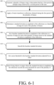
- a radar transceiver Instead of generating a typical chirp pattern with individual chirps separated by long idle periods, a radar transceiver generates a multiple-chirp pattern with groupings of multiple chirps separated by long idles periods, for each frame.
- a frame being a duration of time during which the chirp pattern that has a first period of multiple chirps followed by a second period of idle time.
- the radar From applying a Fourier transform (e.g., a fast Fourier transform, or "FFT") to receiver signals (e.g., digital beat signals including baseband data) for each frame, the radar determines an amplitude of the receiver signals, as a function of range, for each frame.
- the radar system computes the standard deviation between the amplitudes of two frames and, for each additional frame, the radar incrementally updates the standard deviation between the amplitudes of the two frames to be inclusive of the amplitude contribution of the additional frame. That is, rather than recalculate the standard deviation from scratch in response to each new frame, the radar system "incrementally" adjusts the previous standard deviation by a fraction of the amplitude of the new frame, which is proportionate to the total quantity of frames generated thus far.
- a Fourier transform e.g., a fast Fourier transform, or "FFT”
- the radar In response to the adjusted standard deviation satisfying a noise threshold, the radar outputs an indication of a living object.
- the techniques of this disclosure enable radar-based detection of living objects with an improved signal-to-noise ratio and therefore greater accuracy when compared to conventional FMCW radar systems. Live object detection is improved by the described systems and techniques without increasing radiation power, power consumption, costs, or computational load relative to a conventional FMCW radar system.
- a FMCW radar system includes an antenna array, a transceiver configured to generate radar signals via the antenna array, and a processing unit.
- the processing unit is configured to direct the transceiver to detect objects by generating, over a plurality of frames, the radar signals having a chirp pattern that has a first period of multiple chirps followed by a second period of idle time.
- the processing unit applies a Fourier transform to reflections of the radar signals obtained within each of the plurality of frames to determine a respective amplitude, as a function of range, for each of the plurality of frames, and based on the respective amplitude for each of the plurality of frames, determines a standard deviation in the amplitude as a function of range for the plurality of frames.
- the processing unit is further configured to, in response to the standard deviation in the amplitude for the plurality of frames satisfying a noise threshold, output an indication of a living object detected during the plurality of frames.
- the processing unit is configured to direct the transceiver to detect objects by generating, for a first plurality of frames, radar signals having a chirp pattern that has a first period of multiple chirps followed by a second period of idle time, determine a respective amplitude as a function of range for each of the first plurality of frames, and determine a baseline standard deviation in the amplitude for the first plurality of frames based on the respective amplitude determined for each of the first plurality of frames.
- the processing unit is further configured to adjust an adaptive noise threshold based on a dynamic noise response of the radar system by smoothing the baseline standard deviation in the amplitude and setting the adaptive noise threshold to the baseline standard deviation in amplitude.
- the processing unit is further configured to, responsive to a standard deviation in amplitude as a function of range for a second plurality of frames generated using the chirp pattern satisfying the adaptive noise threshold, output an indication of a living object detected during the second plurality of frames.
- the processing unit is configured to direct the transceiver to detect objects by generating, for a first plurality of frames, radar signals having a chirp pattern that has a first period of multiple chirps followed by a second period of idle time.
- the processing unit determines a respective amplitude as a function of range for each of the first plurality of frames and determines a first standard deviation for the first plurality of frames based on the respective amplitude determined for each of the first plurality of frames.
- the processing unit is further configured to store, in a memory, a previous mean amplitude equal to a mean amplitude as a function of range for the first plurality of frames, direct the transceiver to generate the chirp pattern in a subsequent frame to the first plurality of frames, and determine a current mean amplitude equal to the previous mean amplitude adjusted by a fraction of an amplitude, as a function of range, of the subsequent frame.
- the fraction of the amplitude of the subsequent frame is equal to a difference between the amplitude of the subsequent frame and the previous mean amplitude, the difference being divided by a total quantity of frames among the first plurality of frames and the subsequent frame.
- the processing unit is further configured to determine a second standard deviation in amplitude as a function of range of the first plurality of frames and the subsequent frame by adjusting the first standard deviation in amplitude by an amount based on the amplitude of the subsequent frame, the previous mean amplitude, and the current mean amplitude. Responsive to the second standard deviation satisfying a noise threshold, the processing unit outputs an indication of a living object detected during the first plurality of frames and the subsequent frame.
- This document also describes computer-readable media having instructions for performing methods by the above-summarized FMCW radar systems.
- Other FMCW radar systems, computer-readable media, and methods are set forth herein, as well as systems and means for performing the aforementioned methods, which are further described below.
- a FMCW radar system uses an atypical (multiple) chirp pattern for each frame. This increases the signal-to-noise ratio (SNR) between amplitudes of reflections from objects that are alive, and amplitudes of reflections from non-living objects and noise, including thermal noise from the radar itself.
- SNR signal-to-noise ratio
- the motion pattern from other objects are generally, not similar to the periodicity and amplitude of a moving chest wall of a child.
- the SNR is increased without increasing radiation power, which aside from preserving electrical power, may reduce some health concerns.
- the example FMCW radar system increases the SNR without increasing computational load, power consumption, or cost.
- the radar system instead of a typical chirp pattern with individual chirps separated by a long idle period, the radar system generates, for a plurality of frames, a repeating-multiple chirp pattern that has a first period of multiple chirps and a second, lengthier period of idle time for each frame.
- the period of idle time can be orders of a magnitude longer than the first period of the frame.
- the FMCW radar system determines a respective amplitude, as a function of range, for each of the plurality of frames.
- the FMCW radar system computes a standard deviation of the amplitude for the plurality of frames.
- the FMCW may incrementally update the standard deviation, as a function of range, as each new frame is generated. That is, rather than recalculate the standard deviation each time a new frame is generated, the FMCW radar system can adjust the standard deviation by an amount proportional to the individual contribution of the amplitude of the new frame relative to the standard deviation of the previous frames.
- the FMCW radar system In response to the standard deviation of the amplitude satisfying a noise threshold, the FMCW radar system outputs an indication of a living object detected during the plurality of frames.
- the FMCW radar system may rely on a predetermined threshold, set to a predetermined level based on observed characteristics of the FMCW radar system.
- the FMCW radar system uses an adaptive noise threshold that changes according to a dynamic noise response of the radar system, including, compensating for power drift in the amplitude of the receiver signals, particularly during power-up.
- the techniques of this disclosure enable FMCW radar-based detection of living objects with an improved signal to noise ratio and therefore greater accuracy when compared to other radar-based detection systems.
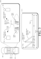
- FIG. 1 illustrates a vehicle 100 in which an example FMCW radar system 102 can detect living objects, e . g ., human and animal living occupants.
- the vehicle 100 can represent other types of motorized vehicles (e.g., a motorcycle, a bus, a tractor, a semi-trailer truck, or construction equipment), types of non-motorized vehicles (e.g., a bicycle), types of railed vehicles (e.g., a train or a trolley car), watercraft (e.g., a boat or a ship), aircraft (e.g., an airplane or a helicopter), or spacecraft (e.g., satellite).
- motorized vehicles e.g., a motorcycle, a bus, a tractor, a semi-trailer truck, or construction equipment
- non-motorized vehicles e.g., a bicycle
- types of railed vehicles e.g., a train or a trolley car
- watercraft e.g., a boat or a ship
- the FMCW radar system 102 (referred to simply as “the radar system 102") is mounted to, or integrated within, the vehicle 100.
- the techniques and systems described herein are not limited to vehicles or automotive contexts, but also apply to other mobile and non-mobile environments (e.g., residential or commercial heating and cooling systems, lighting systems, security systems) where live-object-detection may be useful, including machinery, robotic equipment, buildings and other structures.
- the radar system 102 is capable of detecting one or more objects that are within proximity to the vehicle 100. Specifically, the radar system 102 is configured for interior, as opposed to exterior, vehicle sensing. The radar system 102 is configured to detect signs of life from objects that are alive and inside the vehicle 100.
- the radar system 102 is located inside the vehicle 100 near the ceiling. In other implementations, the radar system 102 can be mounted in other parts of the vehicle 100.
- the radar system 102 transmits radar signals and receives radar reflections in a portion of the vehicle 100 that is encompassed by a field-of-view 104.
- the field-of-view 104 includes one or more areas occupied by passengers or other living occupants of the vehicle 100.
- a living object 108 which may sometimes be referred to as a living target, is seated in a front or rear passenger seat, which is within the field-of-view 104.
- the radar system 102 is shown having three different parts positioned at different locations of the vehicle 100.
- the radar system 102 can include additional or fewer parts in some implementations.
- the parts of the radar system 102 can be designed and positioned to provide a particular field of view 104 that encompasses a specific region of interest.
- Example fields of view 104 include a 360-degree field of view, one or more 180-degree fields of view, one or more 90-degree fields of view, and so forth, which can overlap ( e.g., for creating a particular size field of view).
- the living object 108 is an infant in a car seat.
- the living object 108 can be any other human or animal occupant that reflects radar signals.
- the radar system 102 and the vehicle 100 are further described with respect to FIG. 2 .
- the radar system 102 is configured to detect the living object 108 by generating, over a plurality of frames, a chirp pattern that has a first period of multiple chirps followed by a second period of idle time for each frame.
- a radar signal 112 is shown in FIG. 1 which includes the chirp pattern described, where in each frame, the radar signal 112 includes a repeating pattern of two or more chirps followed by an idle period where the radar signal 112 remains silent until the next frame.
- the period of idle time is longer than the period of multiple chirps.
- the first period of each frame with the multiple chirps is approximately two or more microseconds and the second period is less than approximately 100 milliseconds.
- the radar system 102 is configured to apply a Fourier transform to the reflected signals corresponding to the pattern of multiple chirps within each of the plurality of frames of the radar signal 112. Using results obtained from application of the transformation, the radar system 102 is configured to determine a respective amplitude, as a function of range, for each of the plurality of frames. From the respective amplitudes, the radar system 102 is configured to determine a standard deviation in the amplitude, as a function of range, for the frames of the radar signal 112.
- the radar system 102 may incrementally update the standard deviation in the amplitude, as each frame is generated. For example, rather than recalculate the standard deviation each time a new frame is generated, the radar system 102 is configured to adjust the standard deviation by a fraction of the amplitude for the new frame. The fraction of the amplitude is proportional to the individual contribution of the new frame relative to the contribution of the previous frames.
- the radar system 102 operates according to a noise threshold.
- the noise threshold is an adaptive threshold that adjusts over time. By adjusting the noise threshold based on changes to a dynamic noise response of the radar system 102, including by compensating for power drift in the amplitude of the radar signal 112, particularly during power-up, the radar system 102 can more accurately detect living objects.
- the radar system 102 is configured to output an alert or other indication of the living object 108 detected during the plurality of frames of the radar signal 112.
- the field-of-view 104 includes one or more areas occupied by passengers of the vehicle 100 and the radar system outputs an indication of living object 108 detected in the vehicle 100.
- a processing unit of the radar system 102 outputs the indication of the living object 108 to an alert system, which in response, outputs an audible, visual, or haptic feedback to a human or machine about an occupant inside an unattended vehicle.
- the alert system may provide an alarm monitoring service which notifies the owner(s) of the vehicle 100 via telephone and if unsuccessful in contacting the owner, contacts help (e.g., local police, fire, or ambulance services).
- help e.g., local police, fire, or ambulance services.
- the alert system may take action, for example, by directing the vehicle 100 to heat, cool, or ventilate the interior of the vehicle 100 in response to receiving an indication of the living object 108.
- the atypical chirp pattern of the radar signal includes a chirp pattern having multiple chirps, instead of a chirp pattern that includes a single chirp which proceeds each idle period of the chirp pattern generated by the radar system 102.
- the atypical chirp pattern of the radar signal increases the SNR between radar reflections detected from living objects and other radar reflections detected from stationary objects and noise.
- the SNR is increased without increasing radiation power of the radar system 102, which aside from preserving electrical power, may reduce some health concerns related to operating the radar system 102 near the living object 108 or other occupants of the vehicle 100.
- the radar system 102 thus increases the SNR without increasing computational load, power consumption, or cost.
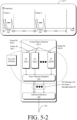
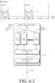
- FIG. 2 illustrates an example implementation of the radar system 102 as part of the vehicle 100.
- the vehicle 100 includes vehicle-based systems 200 that rely on data from the radar system 102, such as an occupancy detector system 202 and an autonomous driving system 204.
- the vehicle-based systems 200 use radar data provided by the radar system 102 to perform a function.
- the autonomous driving system 204 takes control of the vehicle 100 in response to the radar system 102 detecting a sleeping driver to bring the vehicle safely to a stop.
- the occupancy detector 202 sounds an alarm of the vehicle 100 and/or ventilates the vehicle 100 in response to the radar system 102 detecting a child or pet inadvertently left in the vehicle 100, unattended.
- the radar system 102 includes a communication interface 206 to transmit the radar data to the vehicle-based systems 200 or to another component of the vehicle 100 over a communication bus of the vehicle 100, for example, when the individual components shown in the radar system 102 are integrated, including at different positions or locations, within the vehicle 100.
- the radar data provided by the communication interface 206 is in a format usable by the vehicle-based systems 200.
- the communication interface 206 may provide information to the radar system 102, such as the speed of the vehicle 100, the interior temperature of the of the vehicle 100, etc. The radar system 102 can use this information to appropriately configure itself.
- the radar system 102 can enter "occupant-detection mode" where the radar system 102 configures itself to generate each frame with a multiple chirp pattern in response to receiving an indication that the vehicle 100 is parked and/or an internal temperature is above or nearing an unsafe temperature for human or animal occupants.
- the radar system 102 also includes at least one antenna array 208 and a transceiver 210 to transmit and receive radar signals.
- the antenna array 208 includes a transmit antenna element, for example, one per each transmit channel.
- a receive antenna element of the antenna array 208 is coupled to each receive channel to receive radar reflections in response to the radar signals.
- the antenna array 208 can include multiple transmit antenna elements and multiple receive antenna elements to configure the radar system 102 as a MIMO (Multiple Input Multiple Output) radar system capable of transmitting multiple distinct waveforms at a given time (e.g., a different waveform per transmit antenna element).
- the antenna elements can be circularly polarized, horizontally polarized, vertically polarized, or a combination thereof.
- the radar system 102 can form beams that are steered or un-steered, and wide or narrow.
- the steering and shaping can be achieved through analog beamforming or digital beamforming.
- the one or more transmitting antenna elements can have an un-steered omnidirectional radiation pattern, or the one or more transmitting antenna elements can produce a wide steerable beam to illuminate a large volume of space.
- the receiving antenna elements can be used to generate hundreds of narrow steered beams with digital beamforming. In this way, the radar system 102 can efficiently monitor an external or internal environment of the vehicle 100 to detect one or more objects within the field-of-view 104.
- the transceiver 210 which may include multiple transceivers, includes circuitry and logic for transmitting radar signals and receiving radar reflections (also sometimes referred to as radar receive signals or radar returns) via the antenna array 208.
- a transmitter of the transceiver 210 includes one or more transmit channels and a receiver of the transceiver 210 includes one or more receive channels, which may be of a similar or different quantity than a quantity of the transmit channels.
- the transmitter and receiver may share a local oscillator (LO) to synchronize operations.
- the transceiver 210 can also include other components not shown, such as amplifiers, mixers, phase shifters, switches, analog-to-digital converters, combiners, and the like.
- the transceiver 210 is primarily configured as a continuous-wave transceiver 210 to execute FMCW operations, and may also include logic to perform in-phase/quadrature (I/Q) operations and/or modulation or demodulation in a variety of ways, including linear-frequency modulations, triangular-frequency modulations, stepped-frequency modulation, or phase modulation.
- the transceiver 210 may be configured to support pulsed-radar operations, as well.
- a frequency spectrum (e.g., range of frequencies) of radar signals and radar reflections can encompass frequencies between one and ten gigahertz (GHz), as one example.
- the bandwidths can be less than one GHz, such as between approximately three hundred megahertz (MHz) and five hundred MHz.
- the frequencies of the transceiver 210 may be associated with millimeter wavelengths.
- the radar system 102 also includes at least one processing unit 212 and computer-readable storage media (CRM) 214.
- the CRM 214 includes a raw-data processing module 218 and a radar control module 220.
- the raw-data processing module 218 and the radar control module 220 can be implemented using hardware, software, firmware, or a combination thereof.
- the processing unit 212 executes instructions for implementing the raw-data processing module 218 and the radar control module 220.
- the raw-data processing module 218 and the radar control module 220 enable the processing unit 212 to process responses from the receive antenna elements in the antenna array 208 to detect the living object 108 and generate radar data for the vehicle-based systems 200.
- the raw-data processing module 218 transforms receiver signals including raw data (e.g., digital beat signals including baseband data) provided by the transceiver 210 into radar data (e.g., an amplitude as a function of range) that is usable by the radar control module 220.
- the radar control module 220 analyzes the radar data obtained over time to map one or more detections, e.g., of living objects.
- the radar control module 220 determines whether a living object 108 is present within the field-of-view 104 using a living-object detector 222 and optionally, an adaptive-threshold adjuster 224.
- the living-object detector 222 causes the radar control module 220 to operate in an occupant-detection mode where the radar signal 112 is analyzed for signs of living objects obscured by (e.g., thermal) noise.
- the living-object detector 222 determines a standard deviation between multiple frames to isolate stationary living objects, which move even if only to breath, from non-living objects, which remain mostly stationary from one frame to the next.
- the living-object detector 222 uses a noise threshold to determine whether the standard deviation at a particular range from the radar system 102 is a living object.
- the noise threshold is set to ensure that the movement is sufficient to indicate presence of a living object. Using the noise threshold, the radar system 102 can differentiate between a living object and either a stationary object or thermal noise produced by the radar system 102.
- the living-object detector 222 may determine a respective amplitude as a function of range for each of M plurality of frames by applying a Fourier transform, such as an FFT, to respective receiver signals of the N chirps in each frame.
- a Fourier transform such as an FFT
- the living-object detector 222 applies a Fourier transform to the receiver signal of each chirp in each frame.
- the results of each of the Fourier transforms are integrated over frames, using non-coherent integration (NCI).
- NCI non-coherent integration
- a standard deviation of the amplitude as a function of range between two or more of the plurality of frames is determined by integrating, using non-coherent integration, results of the Fourier transform applied to the respective receiver signal of each new frame M, with the standard deviation in amplitude over the previously received, plurality of frames 1 through ( M - 1).
- the adaptive-threshold adjuster 224 is an optional component of the radar system 102.
- the living-object detector 222 may rely on the adaptive-threshold adjuster 224 to set the noise threshold used by the living-object detector 222 while the radar system 102 is operating in the occupant-detection mode.
- the adaptive-threshold adjuster 224 automatically sets the noise threshold used, by the radar system 102, to detect a living object by accounting for the environmental changes. For example, during power-on, the radar signal 112 may undergo power drift until settling down to a normal level. As the effects of power drift become less, the adaptive-threshold adjuster 224 modifies the noise threshold settle to a nominal level. Over time, as the environment continues to change, the adaptive-threshold adjuster 224 increases and decreases the noise threshold with changes in noise levels, smoothing changes to the noise threshold between sequential frames.
- the radar control module 220 produces the radar data for the vehicle-based system 200.
- Example types of radar data include a Boolean value that indicates whether or not the object 108 is present within a particular region of interest, a number that represents a characteristic of the object 108 ( e.g., position, speed, or direction of motion), or a value that indicates the type of object 108 detected ( e.g., a living or non-living).
- the radar control module 220 configures the transceiver 210 to emit radar signals and detect radar reflections via the antenna array 208.
- the radar control module 220 outputs information associated with the radar reflections detected from radar signals that reach objects, such as the object 108.
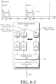
- FIG. 3 illustrates an example operation 300 of the radar system 102.
- the living object 108 is located at a particular slant range and angle from the antenna array of the radar system 102.
- the radar system 102 transmits and receives a radar signal 112-1, which is an example of a frame 308 of the radar signal 112.
- the radar signal 112-1 is transmitted as a radar transmit signal 302.
- At least a portion of the radar transmit signal 302 is reflected by the living object 108. This reflected portion represents a radar reflection or a radar receive signal 304.
- the radar system processes the radar receive signal 304 to extract data for a vehicle-based system, such as the vehicle-based systems 200.
- an amplitude of the radar receive signal 304 is smaller than an amplitude of the radar transmit signal 302 due to losses incurred during propagation and reflection.
- the radar transmit signal 302 is illustrated as having a single waveform, the radar transmit signal 302 can be composed of multiple radar transmit signals 302 that have distinct waveforms to support MIMO operations.
- the radar receive signal 304 can be composed of multiple radar receive signals 302 that also have different waveforms.
- the radar transmit signal 302 includes one or more chirps 306-1 to 306-N, where N represents a positive integer.
- the radar system 102 can transmit the chirps 306-1, 306-2, ..., 306-N (collectively "the chirps 306") in a continuous sequence or transmit the chirps as time-separated pulses.
- the radar transmit signal 302 can include a quantity of M frames 308, where M represents a positive integer.
- Individual frequencies of the chirps 306 can increase or decrease over time, but the slope or rate of change in the individual frequencies between the chirps 306 can be consistent.
- the radar system 102 employs a single-slope cycle to linearly decrease the frequencies of the chirps 306 over time.
- Other types of frequency modulations are also possible, including a two-slope cycle and/or a non-linear frequency modulation.
- transmission characteristics of the chirps 306 e.g., bandwidth, center frequency, duration, and transmit power
- the radar receive signal 304 represents a delayed version of the radar transmit signal 302.
- the amount of delay is proportional to the slant range (e.g., distance) from the antenna array 208 of the radar system 102 to the living object 108.
- this delay represents a summation of a time it takes for the radar transmit signal 302 to propagate from the radar system 102 to the living object 108 and a time it takes for the radar receive signal 304 to propagate from the living object 108 to the radar system 102. If the living object 108 and/or the radar system 102 is moving, the radar receive signal 304 is shifted in frequency relative to the radar transmit signal 302 due to the Doppler effect.
- characteristics of the radar receive signal 304 are dependent upon motion of the living object 108 and/or motion of the vehicle 100. Similar to the radar transmit signal 302, the radar receive signal 304 is composed of one or more of the chirps 306. The chirps 306 enable the radar system 102 to make multiple observations of the object living 108 over a first time period during each of the frames 308.
- the radar signal 112-1 is based on a waveform structure with a combination of fast chirps and very slow chirps (or idle time) in each frame 308.
- the fast chirps 306 are followed by an idle period.
- the waveform includes N fast chirps 306 during a repetition period of a few microseconds. After the N fast chirps 306, a long idle period of the waveform precedes the start of the next frame 308. The idle period may be as long as 100 milliseconds.
- Each set of N fast chirps 306 in combination with the idle period forms a slow frame 308.
- the transceiver 210 accepts a control signal from the processing unit 212. Using the control signal, the processing unit 212 directs the transceiver 210 to operate in a particular configuration or operational mode, such as an occupant-detection mode. As an example, the control signal can specify types of waveforms to be generated by the transmit channels of the transceiver 210.
- Different waveform types can have a different N quantity of chirps 306, M quantity of frames 308, chirp durations, frame durations, center frequencies, bandwidths, types of frequency modulation (e.g., a single-slope modulation, a two-slope modulation, a linear modulation, or a non-linear modulation), or types of phase modulations (e.g., different orthogonal coding sequences).
- the control signal can specify which transmit channels are enabled or disabled. In the example of FIG. 3 , the control signal specifies the characteristics of the radar signal 112-1 as having a quantity of N chirps 306, a recurring idle time at the end of each frame 308, and a total quantity of M frames 308.
- the transceiver 210 Based on the control signal, the transceiver 210 generates a frequency-modulated radar signal 112-1 at radio frequencies on the transmit channels.
- a phase modulator of the transceiver 210 may modulate phases of chirps within the frequency-modulated radar signal to generate a frequency-modulated and phase-modulated radar signal in cases where phase-modulation is used.
- the phases of the chirps 306 can be determined based on a coding sequence specified by the control signal.
- the control signal directs the transceiver 210 to transmit a FMCW radar signal and in return receive FMCW radar reflections from objects in the field-of-view 104.
- the receive antenna elements of the antenna array 208 receive a version of a radar receive signal 304. Relative phase differences between these versions of the radar receive signal 304 are due to differences in locations of the receive antenna elements and the transmit antenna elements of the antenna array 208.
- a mixer performs a beating operation, which down-converts and demodulates the radar receive signals 304 to generate corresponding beat signals.
- a frequency of a beat signal for a chirp pattern that relies on a chirp pattern with a single chirp 306 between each idle period corresponds to a difference in frequency between the radar transmit signal 302 and the radar receive signal 304. This frequency difference is proportional to a slant range between the antenna array 208 and the object 108.
- the beat signal for each frame 308 represents a combination of the beat signals for some or all of the chirps 306 within each frame 308.
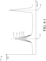
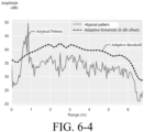
- FIG. 4-1 illustrates amplitudes, as a function of range, of multiple radar signals received by an example FMCW radar system.
- the radar system 102 receives radar signals 112-2 through 112-6, which are each an example of a frame 308 of the radar signal 112.
- the radar system 102 determines amplitudes of the radar signals 112-2 through 112-6 as a function of range.
- Each of the radar signals 112-2 through 112-6 is unique to a single frame 308.
- the peak amplitude of each of the radar signals 112-2 through 112-6 decreases from one signal to the next.
- the change in amplitude across a sequence of frames 308 at the range 402 indicates movement at the range 402.
- the amplitude of the radar signals 112-2 through 112-6 remains consistent from one frame 308 to the next.
- Example 4 The radar system of any of the preceding examples, wherein the processing unit is configured to apply the Fourier transform to the multiple chirps by applying the Fourier transform to a common receiver signal for the multiple chirps in each frame over the plurality of frames.
- Example 14 The radar system of any of the preceding examples, wherein the standard deviation is a first standard deviation, wherein the processing unit is further configured to: direct the transceiver to generate, for a subsequent frame, the chirp pattern that has the first period of multiple chirps followed by the second period of idle time; determine, based in part on the first standard deviation and a respective amplitude as a function of range for the subsequent frame, a second standard deviation in the respective amplitude for the reflections within the subsequent frame and each of the plurality of frames; and in response to the second standard deviation not satisfying the noise threshold, refrain from outputting the indication of the object.
- the processing unit is further configured to: direct the transceiver to generate, for a subsequent frame, the chirp pattern that has the first period of multiple chirps followed by the second period of idle time; determine, based in part on the first standard deviation and a respective amplitude as a function of range for the subsequent frame, a second standard deviation in the respective amplitude for the reflections within the subsequent frame
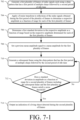
- Example 19 A computer-readable storage medium comprising instructions that, when executed by a processing unit of a radar system, cause the processing unit to: direct a transceiver of the radar system to generate a plurality of frames of radar signals having a chirp pattern that has a first period of multiple chirps followed by a second period of idle time; apply a Fourier transform to respective reflections obtained during the first period of each of the plurality of frames to determine a respective amplitude of the reflections as a function of range for each of the plurality of frames; based on the respective amplitude of the reflections for each of the plurality of frames, determine a standard deviation in the respective amplitude for the reflections within each of the plurality of frames; and in response to the standard deviation in the respective amplitude for any of the reflections within the plurality of frames satisfying a noise threshold, output, an indication of a living object detected during the plurality of frames.
- Example 21 A radar system comprising: an antenna array; a transceiver configured to generate radar signals via the antenna array; and a processing unit configured to: direct the transceiver to generate, over a first plurality of frames, the radar signals having a chirp pattern that has a first period of multiple chirps followed by a second period of idle time; determine a respective amplitude as a function of range for the reflections obtained during each of the first plurality of frames; based on the respective amplitude for the reflections obtained during each of the plurality of frames, determine a baseline standard deviation in amplitude as a function of range for the first plurality of frames; adjust an adaptive noise threshold based on a dynamic noise response of the radar system by smoothing the baseline standard deviation for the first plurality of frames and setting the adaptive noise threshold to the baseline standard deviation after the smoothing; and responsive to a standard deviation in amplitude as a function of range for a second plurality of frames generated using the chirp pattern satisfying the adaptive noise threshold, output an indication of a living object detected
- Example 30 The radar system of any of the preceding examples, wherein the second period of idle time is longer than the first period of multiple chirps.
- Example 32 The radar system of any of the preceding examples, wherein the first period is approximately two or more microseconds and the second period is less than approximately 100 milliseconds.
- Example 33 The radar system of any of the preceding examples, wherein the processing unit is further configured to: direct the transceiver to generate the chirp pattern in a third frame after the second plurality of frames; determine, based on the standard deviation in amplitude for the second plurality of frames and an amplitude as a function of range for the third frame, a standard deviation in amplitude as a function of range for the third frame; and based on whether the standard deviation in amplitude for the third frame satisfies the adaptive noise threshold, output or refrain from outputting an indication of a living object detected during the third frame.
- Example 34 The radar system of any of the preceding examples, wherein the processing unit is further configured to: smooth the standard deviation in amplitude for the second plurality of frames; and set the adaptive noise threshold for the third frame to the smoothed, standard deviation in amplitude for the second plurality of frames.
- Example 35 The radar system of any of the preceding examples, wherein the processing unit is further configured to optionally add an offset to the smoothed, standard deviation in amplitude for the second plurality of frames before setting the adaptive noise threshold for the third frame to the smoothed, standard deviation for the second plurality of frames.
- Example 36 The radar system of any of the preceding examples, wherein the processing unit is further configured to: output the indication of the living object detected during the third frame in response to the standard deviation for the third frame satisfying the adaptive noise threshold.
- Example 37 The radar system of any of the preceding examples, wherein the processing unit is further configured to: determine a previous mean amplitude equal to a mean amplitude for the second plurality of frames; determine a current mean amplitude equal to the previous mean amplitude incremented by a fraction of the amplitude of the third frame, the fraction of the amplitude of the third frame being equal to a difference between the amplitude of the third frame and the previous mean amplitude, the difference being divided by a total quantity of frames among the second plurality of frames and the third frame; determine the standard deviation in amplitude for the third frame by incrementing the baseline standard deviation by an amount determined based on the amplitude of the third frame, the previous mean amplitude, and the current mean amplitude; and store the current mean amplitude as the previous mean amplitude for use in subsequently incrementing the current mean amplitude.
- Example 38 The radar system of any of the preceding examples, wherein the amount determined based on the range of the third frame, the previous mean, and the current mean is based on a product of the amplitude of the third frame minus the previous mean amplitude and the amplitude of the third frame minus the current mean amplitude.
- Example 39 A computer-readable storage medium comprising instructions that, when executed by a processing unit of a radar system, cause the processing unit to: direct a transceiver to generate, over a first plurality of frames, radar signals having a chirp pattern that has a first period of multiple chirps followed by a second period of idle time; determine a respective amplitude as a function of range for reflections of the radar signals obtained during each of the first plurality of frames; based on the respective amplitude for the reflections obtained during each of the plurality of frames, determine a baseline standard deviation in amplitude as a function of range for the first plurality of frames; adjust an adaptive noise threshold based on a dynamic noise response of the radar system by smoothing the baseline standard deviation for the first plurality of frames and setting the adaptive noise threshold to the baseline standard deviation after the smoothing; and responsive to a standard deviation in amplitude as a function of range for a second plurality of frames generated using the chirp pattern satisfying the adaptive noise threshold, output an indication of a living object detected during
- Example 40 A method comprising: generating, by a radar system, over a first plurality of frames, radar signals having a chirp pattern that has a first period of multiple chirps followed by a second period of idle time; determining, by the radar system, a respective amplitude as a function of range for reflections of the radar signals obtained during each of the first plurality of frames; based on the respective amplitude for the reflections obtained during each of the plurality of frames, determining, by the radar system, a baseline standard deviation in amplitude as a function of range for the first plurality of frames; adjusting, by the radar system, an adaptive noise threshold based on a dynamic noise response of the radar system by smoothing the baseline standard deviation for the first plurality of frames and setting the adaptive noise threshold to the baseline standard deviation after the smoothing; and responsive to a standard deviation in amplitude as a function of range for a second plurality of frames generated using the chirp pattern satisfying the adaptive noise threshold, outputting, by the radar system, an indication of a living object
- a radar system comprising: an antenna array; a transceiver configured to generate radar signals via the antenna array; and a processing unit configured to: direct the transceiver to generate a first plurality of frames of radar signals having a chirp pattern that has a first period of multiple chirps followed by a second period of idle time; apply a Fourier transform to reflections of the radar signals obtained within the first plurality of frames to determine a respective amplitude, as a function of range, for each of the first plurality of frames; determine a first standard deviation in amplitude for the first plurality of frames based on the respective amplitude determined for each of the first plurality of frames; store a previous mean amplitude equal to a mean amplitude for the first plurality of frames; direct the transceiver to generate the chirp pattern in a subsequent frame to the first plurality of frames; determine a current mean amplitude equal to the previous mean amplitude incremented by a fraction of an amplitude, as a function of range, of the
- Example 42 The radar system of any of the preceding examples, wherein the processing unit is further configured to: store the current mean amplitude as the previous mean amplitude for subsequently incrementing the current mean for another subsequent frame.
- Example 43 The radar system of any of the preceding examples, wherein the processing unit is further configured to: direct the transceiver to generate the chirp pattern in the other subsequent frame; determine the current mean amplitude being equal to the previous mean amplitude incremented by a fraction of an amplitude, as a function of range, of the other subsequent frame, the fraction of the amplitude of the other subsequent frame being equal to a difference between the amplitude of the other subsequent frame and the previous mean amplitude, the difference being divided by a total quantity of frames among the first plurality of frames, the subsequent frame, and the other subsequent frame; and determine a third standard deviation in amplitude for the first plurality of frames, the subsequent frame, and the other subsequent frame by incrementing the second standard deviation by a function of the range of the subsequent frame, the previous mean, and the current mean; and responsive to the third standard deviation satisfying the noise threshold, output an indication of a living object detected during the first plurality of frames, the subsequent frame, and the other subsequent frame.
- Example 44 The radar system of any of the preceding examples, wherein the function of the range of the subsequent frame, the previous mean amplitude, and the current mean amplitude is based on a product of the amplitude of the subsequent frame minus the previous mean amplitude and the amplitude of the subsequent frame minus the current mean amplitude.
- Example 45 The radar system of any of the preceding examples, wherein the processing unit is configured to apply the Fourier transform to the first plurality of frames by applying the Fourier transform to respective receiver signals of each of the multiple chirps in each frame.
- Example 46 The radar system of any of the preceding examples, wherein the processing unit is further configured to apply the Fourier transform to the first plurality of frames by integrating, using non-coherent integration, results of the applying the Fourier transform to the respective receiver signal of each chirp from the multiple chirps in each frame.
- Example 47 The radar system of any of the preceding examples, wherein the processing unit is configured to apply the Fourier transform to the first plurality of frames by applying the Fourier transform to a common receiver signal of the multiple chirps in each frame.
- Example 48 The radar system of any of the preceding examples, wherein the processing unit is configured to determine the common receiver signal of the multiple chirps in each frame by averaging the respective receiver signals of the multiple chirps in that frame.
- Example 49 The radar system of any of the preceding examples, wherein the processing unit is configured to determine the common receiver signal of the multiple chirps in each frame by summing the respective receiver signals of the multiple chirps in that frame.
- Example 50 The radar system of any of the preceding examples, wherein the second period of idle time is longer than the first period of multiple chirps.
- Example 51 The radar system of any of the preceding examples, wherein the processing unit is further configured to determine the first standard deviation for the first plurality of frames or the mean amplitude for the first plurality of frames by compensating for false triggers to detections resulting from power drift of the radar system.
- Example 52 The radar system of any of the preceding examples, wherein the processing unit is further configured to incrementally compensate for the false triggers to detections resulting from the power drift.
- Example 53 The radar system of any of the preceding examples, wherein the noise threshold is a predetermined threshold based on radar characteristics of the radar system.
- Example 54 The radar system of any of the preceding examples, wherein the noise threshold is an adaptive noise threshold and the processing unit is further configured to adjust the adaptive noise threshold based on a dynamic noise response of the radar system.
- the noise threshold is an adaptive noise threshold and the processing unit is further configured to adjust the adaptive noise threshold based on a dynamic noise response of the radar system.
- Example 55 The radar system of any of the preceding examples, wherein the first standard deviation is a baseline standard deviation and the processing unit is further configured to: determine the adaptive noise threshold by smoothing the baseline standard deviation and setting the adaptive noise threshold to the baseline standard deviation.
- Example 56 The radar system of any of the preceding examples, wherein the processing unit is further configured to optionally add an offset to the baseline standard deviation after smoothing the baseline standard deviation to determine the adaptive noise threshold.
- Example 57 The radar system of any of the preceding examples, wherein the processing unit is further configured to: direct the transceiver to generate the chirp pattern in another subsequent frame following the subsequent frame; determine, based in part on the second standard deviation and a respective amplitude for the other subsequent frame, a third standard deviation; and in response to the third standard deviation not satisfying the noise threshold, refrain from outputting an indication of an object detected in the other subsequent frame.
- Example 58 The radar system of any of the preceding examples, wherein the transceiver includes a transmitter and the receiver.
- Example 59 A computer-readable storage medium comprising instructions that, when executed by a processing unit of a radar system, cause the processing unit to: direct a transmitter and a receiver of the radar system to generate a first plurality of frames of radar signals having a chirp pattern that has a first period of multiple chirps followed by a second period of idle time; apply a Fourier transform to reflections of the radar signals obtained within the first plurality of frames to determine a respective amplitude, as a function of range, for each of the first plurality of frames; determine a first standard deviation in amplitude for the first plurality of frames based on the respective amplitude determined for each of the first plurality of frames; store a previous mean amplitude equal to a mean amplitude for the first plurality of frames; direct the transceiver to generate the chirp pattern in a subsequent frame to the first plurality of frames; determine a current mean amplitude equal to the previous mean amplitude incremented by a fraction of an amplitude, as a function of range
- Example 60 A method comprising: generating, by a radar system, a first plurality of frames of radar signals having a chirp pattern that has a first period of multiple chirps followed by a second period of idle time; applying a Fourier transform to reflections of the radar signals obtained within the first plurality of frames to determine a respective amplitude, as a function of range, for each of the first plurality of frames; determining a first standard deviation in amplitude for the first plurality of frames based on the respective amplitude determined for each of the first plurality of frames; storing, by the radar system, a previous mean amplitude equal to a mean amplitude for the first plurality of frames; generating, by the radar system, the chirp pattern in a subsequent frame to the first plurality of frames; determining a current mean amplitude equal to the previous mean amplitude incremented by a fraction of an amplitude, as a function of range, of the subsequent frame, the fraction of the range of the subsequent frame being equal to a difference between
Landscapes
- Engineering & Computer Science (AREA)
- Radar, Positioning & Navigation (AREA)
- Remote Sensing (AREA)
- Physics & Mathematics (AREA)
- Computer Networks & Wireless Communication (AREA)
- General Physics & Mathematics (AREA)
- Electromagnetism (AREA)
- Signal Processing (AREA)
- Radar Systems Or Details Thereof (AREA)
Applications Claiming Priority (2)
| Application Number | Priority Date | Filing Date | Title |
|---|---|---|---|
| US16/825,170 US11385344B2 (en) | 2020-03-20 | 2020-03-20 | Frequency-modulated continuous-wave (FMCW) radar-based detection of living objects |
| EP21151688.5A EP3882652B1 (fr) | 2020-03-20 | 2021-01-14 | Détection d'objets vivants à base de radar à ondes continues modulées en fréquence (fmcw) |
Related Parent Applications (2)
| Application Number | Title | Priority Date | Filing Date |
|---|---|---|---|
| EP21151688.5A Division-Into EP3882652B1 (fr) | 2020-03-20 | 2021-01-14 | Détection d'objets vivants à base de radar à ondes continues modulées en fréquence (fmcw) |
| EP21151688.5A Division EP3882652B1 (fr) | 2020-03-20 | 2021-01-14 | Détection d'objets vivants à base de radar à ondes continues modulées en fréquence (fmcw) |
Publications (2)
| Publication Number | Publication Date |
|---|---|
| EP4530671A2 true EP4530671A2 (fr) | 2025-04-02 |
| EP4530671A3 EP4530671A3 (fr) | 2025-06-11 |
Family
ID=74184526
Family Applications (2)
| Application Number | Title | Priority Date | Filing Date |
|---|---|---|---|
| EP21151688.5A Active EP3882652B1 (fr) | 2020-03-20 | 2021-01-14 | Détection d'objets vivants à base de radar à ondes continues modulées en fréquence (fmcw) |
| EP25157065.1A Pending EP4530671A3 (fr) | 2020-03-20 | 2021-01-14 | Détection radar à onde continue modulée en fréquence (fmcw) d'objets vivants |
Family Applications Before (1)
| Application Number | Title | Priority Date | Filing Date |
|---|---|---|---|
| EP21151688.5A Active EP3882652B1 (fr) | 2020-03-20 | 2021-01-14 | Détection d'objets vivants à base de radar à ondes continues modulées en fréquence (fmcw) |
Country Status (3)
| Country | Link |
|---|---|
| US (2) | US11385344B2 (fr) |
| EP (2) | EP3882652B1 (fr) |
| CN (2) | CN118294944A (fr) |
Families Citing this family (21)
| Publication number | Priority date | Publication date | Assignee | Title |
|---|---|---|---|---|
| JP7241082B2 (ja) * | 2018-08-10 | 2023-03-16 | 古野電気株式会社 | 船舶操縦支援システム、船舶制御装置、船舶制御方法、及びプログラム |
| US11709245B2 (en) * | 2019-04-29 | 2023-07-25 | Adnoviv Inc. | System and methods for radar-based detection of people in a room |
| US11396309B2 (en) * | 2020-04-03 | 2022-07-26 | Toyota Connected North America, Inc. | Management of vehicle sensors and responses to sensor data |
| KR102860885B1 (ko) * | 2020-05-20 | 2025-09-18 | 삼성전자주식회사 | 차량 제어 방법 및 장치 |
| US11381330B2 (en) | 2020-07-07 | 2022-07-05 | Aptiv Technologies Limited | Point-source model for simulating near-field effects from structures of an antenna |
| EP3943966A1 (fr) * | 2020-07-22 | 2022-01-26 | Infineon Technologies AG | Dispositifs de radar et procédés pour dispositifs de radar |
| TWI762243B (zh) * | 2021-03-17 | 2022-04-21 | 緯創資通股份有限公司 | 頻率調變連續波雷達、數位訊號處理方法與表徵資訊偵測方法 |
| US20240319332A1 (en) * | 2021-09-23 | 2024-09-26 | Intel Corporation | Apparatus, system, and method of scheduling radar transmissions |
| DE102022103818A1 (de) * | 2022-02-17 | 2023-08-17 | Gestigon Gmbh | Verfahren und system zum erkennen eines sitzbelegungszustands einer sitzanordnung auf basis von radarpunktwolken |
| SE546203C2 (en) * | 2022-06-03 | 2024-07-02 | Husqvarna Ab | Method for controlling a robotic lawnmower in dependence of analysis of information acquired by means of a radar transceiver and a control unit therefor |
| CN115130501B (zh) * | 2022-06-14 | 2025-08-15 | 森思泰克河北科技有限公司 | 目标对象检测方法、装置、计算机设备和存储介质 |
| CN115140304B (zh) * | 2022-06-20 | 2024-10-29 | 深圳市唐诚兴业科技有限公司 | 一种无人机智能侦测防控系统 |
| US12504510B2 (en) * | 2022-06-30 | 2025-12-23 | Gm Cruise Holdings Llc | Adaptive differential quantization for ranging sensors |
| US20240201779A1 (en) * | 2022-12-15 | 2024-06-20 | Amazon Technologies, Inc. | Presence detection with dynamic radar operating modes |
| US12115937B2 (en) * | 2022-12-20 | 2024-10-15 | T-Mobile Innovations Llc | On-board diagnostic second generation module incorporating a low power radar-based sensor |
| CN117031464B (zh) * | 2023-07-25 | 2024-08-30 | 南京航空航天大学 | 一种舱内运动活体与动目标干扰区分方法和装置 |
| WO2025027770A1 (fr) * | 2023-08-01 | 2025-02-06 | 三菱電機株式会社 | Dispositif de détection d'occupant et procédé de détection d'occupant |
| US20250093497A1 (en) * | 2023-09-19 | 2025-03-20 | Aptiv Technologies AG | Range And Range Rate Estimation For Stepped Frequency Waveform With Constant Pulse Repetition Period |
| DE102023130585A1 (de) * | 2023-11-06 | 2025-05-08 | Valeo Schalter Und Sensoren Gmbh | Verfahren zum erkennen von störungen in einem radarsystem |
| US20250271567A1 (en) * | 2024-02-28 | 2025-08-28 | Clarion Corporation of America | Seat occupancy sensor system for vehicles and method of using the same |
| CN118980999B (zh) * | 2024-08-28 | 2025-03-04 | 复睿智行智能科技(上海)有限公司 | 一种基于毫米波雷达点云占用栅格分析的两轮车入座检测方法 |
Family Cites Families (46)
| Publication number | Priority date | Publication date | Assignee | Title |
|---|---|---|---|---|
| US3114148A (en) * | 1958-09-09 | 1963-12-10 | Packard Bell Electronics Corp | Radar systems |
| US5508706A (en) * | 1991-09-30 | 1996-04-16 | Trw Inc. | Radar signal processor |
| US5886662A (en) * | 1997-06-18 | 1999-03-23 | Zai Amelex | Method and apparatus for remote measurement of terrestrial biomass |
| US6064334A (en) * | 1998-07-15 | 2000-05-16 | Trw Inc. | Clutter resistant target detector |
| US6762712B2 (en) * | 2001-07-26 | 2004-07-13 | Time Domain Corporation | First-arriving-pulse detection apparatus and associated methods |
| US6753780B2 (en) * | 2002-03-15 | 2004-06-22 | Delphi Technologies, Inc. | Vehicle occupant detection system and method using radar motion sensor |
| JP4016826B2 (ja) * | 2002-12-10 | 2007-12-05 | 株式会社デンソー | 物標識別方法及び装置、プログラム |
| US7339517B2 (en) * | 2003-12-16 | 2008-03-04 | Murata Manufacturing Co., Ltd. | Radar |
| US7348880B2 (en) | 2005-07-18 | 2008-03-25 | Delphi Technologies, Inc. | Occupant detection and temperature forewarn safety system and method |
| US7880672B1 (en) * | 2007-09-17 | 2011-02-01 | Sandia Corporation | Generating nonlinear FM chirp radar signals by multiple integrations |
| US20100152600A1 (en) * | 2008-04-03 | 2010-06-17 | Kai Sensors, Inc. | Non-contact physiologic motion sensors and methods for use |
| US7880671B2 (en) | 2008-09-18 | 2011-02-01 | Raytheon Company | Electromagnetic (EM) solver using a shooting bouncing ray (SBR) technique |
| US7760131B2 (en) * | 2008-09-18 | 2010-07-20 | Raytheon Company | All-digital line-of-sight (LOS) processor architecture |
| JP2011215031A (ja) * | 2010-03-31 | 2011-10-27 | Toshiba Corp | 人感センサおよび空調装置 |
| US20130300573A1 (en) * | 2010-05-20 | 2013-11-14 | Lifeflow Technologies, Inc. | Patient monitoring and surveillance system, methods, and devices |
| US9383438B2 (en) * | 2011-04-04 | 2016-07-05 | Mitsubishi Electric Corporation | Presence detection system, presence detection method, and program |
| WO2013088938A1 (fr) * | 2011-12-12 | 2013-06-20 | 三菱電機株式会社 | Dispositif radar |
| CA2774377C (fr) * | 2012-02-02 | 2017-05-02 | Raytheon Canada Limited | Detecteur reposant sur des connaissances |
| JP6031267B2 (ja) * | 2012-06-21 | 2016-11-24 | 古野電気株式会社 | 干渉検出装置、干渉除去器、レーダ装置、干渉検出方法および干渉検出用プログラム |
| JP5477424B2 (ja) * | 2012-07-02 | 2014-04-23 | 沖電気工業株式会社 | 物体検知装置、物体検知方法及びプログラム |
| US9594159B2 (en) * | 2013-07-15 | 2017-03-14 | Texas Instruments Incorporated | 2-D object detection in radar applications |
| JP6093261B2 (ja) * | 2013-07-19 | 2017-03-08 | 株式会社日本自動車部品総合研究所 | 監視装置およびプログラム |
| EP3033634B1 (fr) * | 2013-08-14 | 2017-05-31 | IEE International Electronics & Engineering S.A. | Détection radar d'occupation de véhicule |
| US9983303B2 (en) * | 2013-10-09 | 2018-05-29 | Zih Corp. | Passive radio frequency identification ranging |
| EP3119639B1 (fr) * | 2014-03-21 | 2020-02-26 | IEE International Electronics & Engineering S.A. | Procédé et systeme de détection d'un enfant sans surveillance |
| CA2891839C (fr) * | 2014-05-16 | 2023-02-14 | Mohamed Mabrouk | Teledetection de respiration humaine |
| WO2015184406A1 (fr) | 2014-05-30 | 2015-12-03 | Texas Tech University System | Radar à interférométrie fmcw hybride pour le positionnement et la surveillance et procédés d'utilisation de celui-ci |
| DE102014212390A1 (de) | 2014-06-27 | 2015-12-31 | Robert Bosch Gmbh | Verfahren zur Objektortung mit einem FMCW-Radar |
| US10627480B2 (en) * | 2014-07-17 | 2020-04-21 | Texas Instruments Incorporated | Distributed radar signal processing in a radar system |
| WO2016057781A1 (fr) * | 2014-10-08 | 2016-04-14 | The University Of Florida Research Foundation, Inc. | Procédé et appareil pour l'acquisition de signes vitaux rapide sans contact sur la base d'un signal radar |
| US10677905B2 (en) * | 2017-09-26 | 2020-06-09 | Infineon Technologies Ag | System and method for occupancy detection using a millimeter-wave radar sensor |
| US10310073B1 (en) * | 2018-02-07 | 2019-06-04 | Infineon Technologies Ag | System and method for determining engagement level of a human being using a millimeter-wave radar sensor |
| US10705198B2 (en) * | 2018-03-27 | 2020-07-07 | Infineon Technologies Ag | System and method of monitoring an air flow using a millimeter-wave radar sensor |
| US10775493B2 (en) | 2018-03-28 | 2020-09-15 | Infineon Technologies Ag | System and method for controlling access to a trunk of a vehicle using a radar sensor |
| US11275170B2 (en) * | 2018-04-06 | 2022-03-15 | Electromagnetic Systems, Inc. | Use of dual processing channels for stationary and moving objects illuminated by radar |
| US10634777B2 (en) | 2018-05-30 | 2020-04-28 | Ford Global Technologies, Llc | Radar odometry for vehicle |
| US11448745B2 (en) * | 2018-06-22 | 2022-09-20 | Asahi Kasei Microdevices Corporation | Sensor device and system, and biometric sensing method and system |
| US11875708B2 (en) | 2018-10-04 | 2024-01-16 | The Regents Of The University Of Michigan | Automotive radar scene simulator |
| US11630197B2 (en) * | 2019-01-04 | 2023-04-18 | Qualcomm Incorporated | Determining a motion state of a target object |
| US11520032B2 (en) * | 2019-02-28 | 2022-12-06 | Samsung Electronics Co., Ltd. | Methods and apparatuses for object presence detection and range estimation |
| US11543511B2 (en) * | 2019-03-11 | 2023-01-03 | Panasonic Intellectual Property Management Co., Ltd. | Radar apparatus and vehicle |
| US10725151B1 (en) * | 2019-05-21 | 2020-07-28 | The Boeing Company | System and method for detecting pulses using fused signal power/phase modulation detection |
| EP3758143A1 (fr) | 2019-06-28 | 2020-12-30 | Aptiv Technologies Limited | Procédé de simulation d'une antenne |
| US11360210B2 (en) * | 2019-07-02 | 2022-06-14 | Intel Corporation | Multi-mode multi-input multi-output (MIMO) radar sensors |
| US11320517B2 (en) * | 2019-08-22 | 2022-05-03 | Qualcomm Incorporated | Wireless communication with enhanced maximum permissible exposure (MPE) compliance |
| JP7234170B2 (ja) * | 2020-02-14 | 2023-03-07 | 株式会社東芝 | 測距装置及び測距方法 |
-
2020
- 2020-03-20 US US16/825,170 patent/US11385344B2/en active Active
-
2021
- 2021-01-14 EP EP21151688.5A patent/EP3882652B1/fr active Active
- 2021-01-14 EP EP25157065.1A patent/EP4530671A3/fr active Pending
- 2021-03-22 CN CN202410436297.XA patent/CN118294944A/zh active Pending
- 2021-03-22 CN CN202110302496.8A patent/CN113495263B/zh active Active
-
2022
- 2022-06-02 US US17/805,155 patent/US11959998B2/en active Active
Also Published As
| Publication number | Publication date |
|---|---|
| EP3882652B1 (fr) | 2025-03-19 |
| US20220299624A1 (en) | 2022-09-22 |
| US11385344B2 (en) | 2022-07-12 |
| CN118294944A (zh) | 2024-07-05 |
| EP4530671A3 (fr) | 2025-06-11 |
| US20210293948A1 (en) | 2021-09-23 |
| CN113495263B (zh) | 2024-03-19 |
| EP3882652A1 (fr) | 2021-09-22 |
| US11959998B2 (en) | 2024-04-16 |
| CN113495263A (zh) | 2021-10-12 |
Similar Documents
| Publication | Publication Date | Title |
|---|---|---|
| EP3882652B1 (fr) | Détection d'objets vivants à base de radar à ondes continues modulées en fréquence (fmcw) | |
| US11209522B2 (en) | Method and apparatus for FMCW radar processing | |
| US9500741B2 (en) | Radar apparatus | |
| US9618616B2 (en) | Radar apparatus | |
| US9134405B2 (en) | Radar apparatus | |
| US9470784B2 (en) | Radar device | |
| CN112526504B (zh) | 根据变化的雷达脉冲重复时间的对象距离和速度检测 | |
| EP3045934A1 (fr) | Dispositif radar, véhicule et procédé de détection de vitesse de corps mobile | |
| KR20190096291A (ko) | 위상을 보정하는 레이더 감지 | |
| US20120249360A1 (en) | Electronic scanning radar apparatus, received wave direction estimating method, and received wave direction estimating program | |
| US8159387B1 (en) | Multi-transmitter interferometry | |
| EP4202489A1 (fr) | Forme d'onde de fréquence échelonnée définie par paramètre pour radar | |
| US20130271310A1 (en) | On-board radar apparatus, detection method, and detection program | |
| US11802960B2 (en) | Phase correcting apparatus and method of transmission signal of vehicle radar, and vehicle radar apparatus with the same | |
| US12449508B2 (en) | Spatial-block code division multiplexing (CDM) for multiple input multiple output (MIMO) waveforms | |
| US20240310505A1 (en) | Multiple-input, multiple-output radar system with range-doppler circulating chirps | |
| EP4024083B1 (fr) | Procédé de transmission et procédé de réception de signal de mesure de vitesse | |
| EP4099047B1 (fr) | Prétraitement de données de mesure radar pour la détection d'objets | |
| US20240036160A1 (en) | Standing wave radar, occupant detection system, and object detection method | |
| EP4579270A1 (fr) | Radar mimo avec détection de chevauchement de signaux réfléchis par des objets | |
| CN118275982A (zh) | 相干分布式雷达中的定时偏移补偿 | |
| CN117908021A (zh) | 一种雷达成像方法及装置 |
Legal Events
| Date | Code | Title | Description |
|---|---|---|---|
| PUAI | Public reference made under article 153(3) epc to a published international application that has entered the european phase |
Free format text: ORIGINAL CODE: 0009012 |
|
| STAA | Information on the status of an ep patent application or granted ep patent |
Free format text: STATUS: THE APPLICATION HAS BEEN PUBLISHED |
|
| AC | Divisional application: reference to earlier application |
Ref document number: 3882652 Country of ref document: EP Kind code of ref document: P |
|
| AK | Designated contracting states |
Kind code of ref document: A2 Designated state(s): AL AT BE BG CH CY CZ DE DK EE ES FI FR GB GR HR HU IE IS IT LI LT LU LV MC MK MT NL NO PL PT RO RS SE SI SK SM TR |
|
| REG | Reference to a national code |
Ref country code: DE Ref legal event code: R079 Free format text: PREVIOUS MAIN CLASS: G01S0013560000 Ipc: G01S0007350000 |
|
| PUAL | Search report despatched |
Free format text: ORIGINAL CODE: 0009013 |
|
| AK | Designated contracting states |
Kind code of ref document: A3 Designated state(s): AL AT BE BG CH CY CZ DE DK EE ES FI FR GB GR HR HU IE IS IT LI LT LU LV MC MK MT NL NO PL PT RO RS SE SI SK SM TR |
|
| RIC1 | Information provided on ipc code assigned before grant |
Ipc: G01S 13/56 20060101ALI20250507BHEP Ipc: G01S 13/536 20060101ALI20250507BHEP Ipc: G01S 13/34 20060101ALI20250507BHEP Ipc: G01S 13/04 20060101ALI20250507BHEP Ipc: G01S 7/41 20060101ALI20250507BHEP Ipc: G01S 7/35 20060101AFI20250507BHEP |
|
| STAA | Information on the status of an ep patent application or granted ep patent |
Free format text: STATUS: REQUEST FOR EXAMINATION WAS MADE |
|
| 17P | Request for examination filed |
Effective date: 20251110 |