EP4530671A2 - Frequency-modulated continuous-wave (fmcw) radar-based detection of living objects - Google Patents
Frequency-modulated continuous-wave (fmcw) radar-based detection of living objects Download PDFInfo
- Publication number
- EP4530671A2 EP4530671A2 EP25157065.1A EP25157065A EP4530671A2 EP 4530671 A2 EP4530671 A2 EP 4530671A2 EP 25157065 A EP25157065 A EP 25157065A EP 4530671 A2 EP4530671 A2 EP 4530671A2
- Authority
- EP
- European Patent Office
- Prior art keywords
- frames
- radar
- standard deviation
- amplitude
- radar system
- Prior art date
- Legal status (The legal status is an assumption and is not a legal conclusion. Google has not performed a legal analysis and makes no representation as to the accuracy of the status listed.)
- Pending
Links
Images


Classifications
-
- G—PHYSICS
- G01—MEASURING; TESTING
- G01S—RADIO DIRECTION-FINDING; RADIO NAVIGATION; DETERMINING DISTANCE OR VELOCITY BY USE OF RADIO WAVES; LOCATING OR PRESENCE-DETECTING BY USE OF THE REFLECTION OR RERADIATION OF RADIO WAVES; ANALOGOUS ARRANGEMENTS USING OTHER WAVES
- G01S13/00—Systems using the reflection or reradiation of radio waves, e.g. radar systems; Analogous systems using reflection or reradiation of waves whose nature or wavelength is irrelevant or unspecified
- G01S13/02—Systems using reflection of radio waves, e.g. primary radar systems; Analogous systems
- G01S13/50—Systems of measurement based on relative movement of target
- G01S13/52—Discriminating between fixed and moving objects or between objects moving at different speeds
- G01S13/536—Discriminating between fixed and moving objects or between objects moving at different speeds using transmission of continuous unmodulated waves, amplitude-, frequency-, or phase-modulated waves
-
- G—PHYSICS
- G01—MEASURING; TESTING
- G01S—RADIO DIRECTION-FINDING; RADIO NAVIGATION; DETERMINING DISTANCE OR VELOCITY BY USE OF RADIO WAVES; LOCATING OR PRESENCE-DETECTING BY USE OF THE REFLECTION OR RERADIATION OF RADIO WAVES; ANALOGOUS ARRANGEMENTS USING OTHER WAVES
- G01S13/00—Systems using the reflection or reradiation of radio waves, e.g. radar systems; Analogous systems using reflection or reradiation of waves whose nature or wavelength is irrelevant or unspecified
- G01S13/02—Systems using reflection of radio waves, e.g. primary radar systems; Analogous systems
- G01S13/04—Systems determining presence of a target
-
- G—PHYSICS
- G01—MEASURING; TESTING
- G01S—RADIO DIRECTION-FINDING; RADIO NAVIGATION; DETERMINING DISTANCE OR VELOCITY BY USE OF RADIO WAVES; LOCATING OR PRESENCE-DETECTING BY USE OF THE REFLECTION OR RERADIATION OF RADIO WAVES; ANALOGOUS ARRANGEMENTS USING OTHER WAVES
- G01S13/00—Systems using the reflection or reradiation of radio waves, e.g. radar systems; Analogous systems using reflection or reradiation of waves whose nature or wavelength is irrelevant or unspecified
- G01S13/02—Systems using reflection of radio waves, e.g. primary radar systems; Analogous systems
- G01S13/06—Systems determining position data of a target
- G01S13/08—Systems for measuring distance only
- G01S13/32—Systems for measuring distance only using transmission of continuous waves, whether amplitude-, frequency-, or phase-modulated, or unmodulated
- G01S13/34—Systems for measuring distance only using transmission of continuous waves, whether amplitude-, frequency-, or phase-modulated, or unmodulated using transmission of continuous, frequency-modulated waves while heterodyning the received signal, or a signal derived therefrom, with a locally-generated signal related to the contemporaneously transmitted signal
- G01S13/345—Systems for measuring distance only using transmission of continuous waves, whether amplitude-, frequency-, or phase-modulated, or unmodulated using transmission of continuous, frequency-modulated waves while heterodyning the received signal, or a signal derived therefrom, with a locally-generated signal related to the contemporaneously transmitted signal using triangular modulation
-
- G—PHYSICS
- G01—MEASURING; TESTING
- G01S—RADIO DIRECTION-FINDING; RADIO NAVIGATION; DETERMINING DISTANCE OR VELOCITY BY USE OF RADIO WAVES; LOCATING OR PRESENCE-DETECTING BY USE OF THE REFLECTION OR RERADIATION OF RADIO WAVES; ANALOGOUS ARRANGEMENTS USING OTHER WAVES
- G01S13/00—Systems using the reflection or reradiation of radio waves, e.g. radar systems; Analogous systems using reflection or reradiation of waves whose nature or wavelength is irrelevant or unspecified
- G01S13/02—Systems using reflection of radio waves, e.g. primary radar systems; Analogous systems
- G01S13/50—Systems of measurement based on relative movement of target
- G01S13/52—Discriminating between fixed and moving objects or between objects moving at different speeds
- G01S13/56—Discriminating between fixed and moving objects or between objects moving at different speeds for presence detection
-
- G—PHYSICS
- G01—MEASURING; TESTING
- G01S—RADIO DIRECTION-FINDING; RADIO NAVIGATION; DETERMINING DISTANCE OR VELOCITY BY USE OF RADIO WAVES; LOCATING OR PRESENCE-DETECTING BY USE OF THE REFLECTION OR RERADIATION OF RADIO WAVES; ANALOGOUS ARRANGEMENTS USING OTHER WAVES
- G01S13/00—Systems using the reflection or reradiation of radio waves, e.g. radar systems; Analogous systems using reflection or reradiation of waves whose nature or wavelength is irrelevant or unspecified
- G01S13/88—Radar or analogous systems specially adapted for specific applications
-
- G—PHYSICS
- G01—MEASURING; TESTING
- G01S—RADIO DIRECTION-FINDING; RADIO NAVIGATION; DETERMINING DISTANCE OR VELOCITY BY USE OF RADIO WAVES; LOCATING OR PRESENCE-DETECTING BY USE OF THE REFLECTION OR RERADIATION OF RADIO WAVES; ANALOGOUS ARRANGEMENTS USING OTHER WAVES
- G01S7/00—Details of systems according to groups G01S13/00, G01S15/00, G01S17/00
- G01S7/02—Details of systems according to groups G01S13/00, G01S15/00, G01S17/00 of systems according to group G01S13/00
- G01S7/35—Details of non-pulse systems
- G01S7/352—Receivers
- G01S7/354—Extracting wanted echo-signals
-
- G—PHYSICS
- G01—MEASURING; TESTING
- G01S—RADIO DIRECTION-FINDING; RADIO NAVIGATION; DETERMINING DISTANCE OR VELOCITY BY USE OF RADIO WAVES; LOCATING OR PRESENCE-DETECTING BY USE OF THE REFLECTION OR RERADIATION OF RADIO WAVES; ANALOGOUS ARRANGEMENTS USING OTHER WAVES
- G01S7/00—Details of systems according to groups G01S13/00, G01S15/00, G01S17/00
- G01S7/02—Details of systems according to groups G01S13/00, G01S15/00, G01S17/00 of systems according to group G01S13/00
- G01S7/41—Details of systems according to groups G01S13/00, G01S15/00, G01S17/00 of systems according to group G01S13/00 using analysis of echo signal for target characterisation; Target signature; Target cross-section
- G01S7/415—Identification of targets based on measurements of movement associated with the target
-
- G—PHYSICS
- G01—MEASURING; TESTING
- G01S—RADIO DIRECTION-FINDING; RADIO NAVIGATION; DETERMINING DISTANCE OR VELOCITY BY USE OF RADIO WAVES; LOCATING OR PRESENCE-DETECTING BY USE OF THE REFLECTION OR RERADIATION OF RADIO WAVES; ANALOGOUS ARRANGEMENTS USING OTHER WAVES
- G01S7/00—Details of systems according to groups G01S13/00, G01S15/00, G01S17/00
- G01S7/02—Details of systems according to groups G01S13/00, G01S15/00, G01S17/00 of systems according to group G01S13/00
- G01S7/41—Details of systems according to groups G01S13/00, G01S15/00, G01S17/00 of systems according to group G01S13/00 using analysis of echo signal for target characterisation; Target signature; Target cross-section
- G01S7/418—Theoretical aspects
-
- G—PHYSICS
- G01—MEASURING; TESTING
- G01S—RADIO DIRECTION-FINDING; RADIO NAVIGATION; DETERMINING DISTANCE OR VELOCITY BY USE OF RADIO WAVES; LOCATING OR PRESENCE-DETECTING BY USE OF THE REFLECTION OR RERADIATION OF RADIO WAVES; ANALOGOUS ARRANGEMENTS USING OTHER WAVES
- G01S7/00—Details of systems according to groups G01S13/00, G01S15/00, G01S17/00
- G01S7/02—Details of systems according to groups G01S13/00, G01S15/00, G01S17/00 of systems according to group G01S13/00
- G01S7/35—Details of non-pulse systems
- G01S7/352—Receivers
- G01S7/356—Receivers involving particularities of FFT processing
Definitions
- Thermal noise generated by an FMCW radar can easily mask the subtle signal variations in amplitude introduced over time by stationary living objects; the radar cross-section of a living object, especially a small child at a sedentary condition (e.g., sleeping), is much smaller than, and therefore can easily be masked by, the radar cross-sections of other objects inside the vehicle.
- the radar cross-section is a measure of how detectable an object is by radar. A larger radar cross-section indicates that an object is more easily detected. Radar reflections that are indicative of a small child's heartbeat or respiration can be indistinguishable from thermal noise.
- SNR signal-to-noise ratio
- Another way to increase the SNR is to increase the duty cycle of the FMCW radar and apply Fourier transforms to the radar reflections to distinguish the reflections caused by living objects from the reflections caused by stationary objects or noise. This, however, comes at the expense of significantly increasing the computational load and power consumption of the FMCW radar.
- a radar transceiver Instead of generating a typical chirp pattern with individual chirps separated by long idle periods, a radar transceiver generates a multiple-chirp pattern with groupings of multiple chirps separated by long idles periods, for each frame.
- a frame being a duration of time during which the chirp pattern that has a first period of multiple chirps followed by a second period of idle time.
- the radar From applying a Fourier transform (e.g., a fast Fourier transform, or "FFT") to receiver signals (e.g., digital beat signals including baseband data) for each frame, the radar determines an amplitude of the receiver signals, as a function of range, for each frame.
- the radar system computes the standard deviation between the amplitudes of two frames and, for each additional frame, the radar incrementally updates the standard deviation between the amplitudes of the two frames to be inclusive of the amplitude contribution of the additional frame. That is, rather than recalculate the standard deviation from scratch in response to each new frame, the radar system "incrementally" adjusts the previous standard deviation by a fraction of the amplitude of the new frame, which is proportionate to the total quantity of frames generated thus far.
- a Fourier transform e.g., a fast Fourier transform, or "FFT”
- the radar In response to the adjusted standard deviation satisfying a noise threshold, the radar outputs an indication of a living object.
- the techniques of this disclosure enable radar-based detection of living objects with an improved signal-to-noise ratio and therefore greater accuracy when compared to conventional FMCW radar systems. Live object detection is improved by the described systems and techniques without increasing radiation power, power consumption, costs, or computational load relative to a conventional FMCW radar system.
- a FMCW radar system includes an antenna array, a transceiver configured to generate radar signals via the antenna array, and a processing unit.
- the processing unit is configured to direct the transceiver to detect objects by generating, over a plurality of frames, the radar signals having a chirp pattern that has a first period of multiple chirps followed by a second period of idle time.
- the processing unit applies a Fourier transform to reflections of the radar signals obtained within each of the plurality of frames to determine a respective amplitude, as a function of range, for each of the plurality of frames, and based on the respective amplitude for each of the plurality of frames, determines a standard deviation in the amplitude as a function of range for the plurality of frames.
- the processing unit is further configured to, in response to the standard deviation in the amplitude for the plurality of frames satisfying a noise threshold, output an indication of a living object detected during the plurality of frames.
- the processing unit is configured to direct the transceiver to detect objects by generating, for a first plurality of frames, radar signals having a chirp pattern that has a first period of multiple chirps followed by a second period of idle time, determine a respective amplitude as a function of range for each of the first plurality of frames, and determine a baseline standard deviation in the amplitude for the first plurality of frames based on the respective amplitude determined for each of the first plurality of frames.
- the processing unit is further configured to adjust an adaptive noise threshold based on a dynamic noise response of the radar system by smoothing the baseline standard deviation in the amplitude and setting the adaptive noise threshold to the baseline standard deviation in amplitude.
- the processing unit is further configured to, responsive to a standard deviation in amplitude as a function of range for a second plurality of frames generated using the chirp pattern satisfying the adaptive noise threshold, output an indication of a living object detected during the second plurality of frames.
- the processing unit is configured to direct the transceiver to detect objects by generating, for a first plurality of frames, radar signals having a chirp pattern that has a first period of multiple chirps followed by a second period of idle time.
- the processing unit determines a respective amplitude as a function of range for each of the first plurality of frames and determines a first standard deviation for the first plurality of frames based on the respective amplitude determined for each of the first plurality of frames.
- the processing unit is further configured to store, in a memory, a previous mean amplitude equal to a mean amplitude as a function of range for the first plurality of frames, direct the transceiver to generate the chirp pattern in a subsequent frame to the first plurality of frames, and determine a current mean amplitude equal to the previous mean amplitude adjusted by a fraction of an amplitude, as a function of range, of the subsequent frame.
- the fraction of the amplitude of the subsequent frame is equal to a difference between the amplitude of the subsequent frame and the previous mean amplitude, the difference being divided by a total quantity of frames among the first plurality of frames and the subsequent frame.
- the processing unit is further configured to determine a second standard deviation in amplitude as a function of range of the first plurality of frames and the subsequent frame by adjusting the first standard deviation in amplitude by an amount based on the amplitude of the subsequent frame, the previous mean amplitude, and the current mean amplitude. Responsive to the second standard deviation satisfying a noise threshold, the processing unit outputs an indication of a living object detected during the first plurality of frames and the subsequent frame.
- This document also describes computer-readable media having instructions for performing methods by the above-summarized FMCW radar systems.
- Other FMCW radar systems, computer-readable media, and methods are set forth herein, as well as systems and means for performing the aforementioned methods, which are further described below.
- a FMCW radar system uses an atypical (multiple) chirp pattern for each frame. This increases the signal-to-noise ratio (SNR) between amplitudes of reflections from objects that are alive, and amplitudes of reflections from non-living objects and noise, including thermal noise from the radar itself.
- SNR signal-to-noise ratio
- the motion pattern from other objects are generally, not similar to the periodicity and amplitude of a moving chest wall of a child.
- the SNR is increased without increasing radiation power, which aside from preserving electrical power, may reduce some health concerns.
- the example FMCW radar system increases the SNR without increasing computational load, power consumption, or cost.
- the radar system instead of a typical chirp pattern with individual chirps separated by a long idle period, the radar system generates, for a plurality of frames, a repeating-multiple chirp pattern that has a first period of multiple chirps and a second, lengthier period of idle time for each frame.
- the period of idle time can be orders of a magnitude longer than the first period of the frame.
- the FMCW radar system determines a respective amplitude, as a function of range, for each of the plurality of frames.
- the FMCW radar system computes a standard deviation of the amplitude for the plurality of frames.
- the FMCW may incrementally update the standard deviation, as a function of range, as each new frame is generated. That is, rather than recalculate the standard deviation each time a new frame is generated, the FMCW radar system can adjust the standard deviation by an amount proportional to the individual contribution of the amplitude of the new frame relative to the standard deviation of the previous frames.
- the FMCW radar system In response to the standard deviation of the amplitude satisfying a noise threshold, the FMCW radar system outputs an indication of a living object detected during the plurality of frames.
- the FMCW radar system may rely on a predetermined threshold, set to a predetermined level based on observed characteristics of the FMCW radar system.
- the FMCW radar system uses an adaptive noise threshold that changes according to a dynamic noise response of the radar system, including, compensating for power drift in the amplitude of the receiver signals, particularly during power-up.
- the techniques of this disclosure enable FMCW radar-based detection of living objects with an improved signal to noise ratio and therefore greater accuracy when compared to other radar-based detection systems.
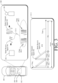
- FIG. 1 illustrates a vehicle 100 in which an example FMCW radar system 102 can detect living objects, e . g ., human and animal living occupants.
- the vehicle 100 can represent other types of motorized vehicles (e.g., a motorcycle, a bus, a tractor, a semi-trailer truck, or construction equipment), types of non-motorized vehicles (e.g., a bicycle), types of railed vehicles (e.g., a train or a trolley car), watercraft (e.g., a boat or a ship), aircraft (e.g., an airplane or a helicopter), or spacecraft (e.g., satellite).
- motorized vehicles e.g., a motorcycle, a bus, a tractor, a semi-trailer truck, or construction equipment
- non-motorized vehicles e.g., a bicycle
- types of railed vehicles e.g., a train or a trolley car
- watercraft e.g., a boat or a ship
- the FMCW radar system 102 (referred to simply as “the radar system 102") is mounted to, or integrated within, the vehicle 100.
- the techniques and systems described herein are not limited to vehicles or automotive contexts, but also apply to other mobile and non-mobile environments (e.g., residential or commercial heating and cooling systems, lighting systems, security systems) where live-object-detection may be useful, including machinery, robotic equipment, buildings and other structures.
- the radar system 102 is capable of detecting one or more objects that are within proximity to the vehicle 100. Specifically, the radar system 102 is configured for interior, as opposed to exterior, vehicle sensing. The radar system 102 is configured to detect signs of life from objects that are alive and inside the vehicle 100.
- the radar system 102 is located inside the vehicle 100 near the ceiling. In other implementations, the radar system 102 can be mounted in other parts of the vehicle 100.
- the radar system 102 transmits radar signals and receives radar reflections in a portion of the vehicle 100 that is encompassed by a field-of-view 104.
- the field-of-view 104 includes one or more areas occupied by passengers or other living occupants of the vehicle 100.
- a living object 108 which may sometimes be referred to as a living target, is seated in a front or rear passenger seat, which is within the field-of-view 104.
- the radar system 102 is shown having three different parts positioned at different locations of the vehicle 100.
- the radar system 102 can include additional or fewer parts in some implementations.
- the parts of the radar system 102 can be designed and positioned to provide a particular field of view 104 that encompasses a specific region of interest.
- Example fields of view 104 include a 360-degree field of view, one or more 180-degree fields of view, one or more 90-degree fields of view, and so forth, which can overlap ( e.g., for creating a particular size field of view).
- the living object 108 is an infant in a car seat.
- the living object 108 can be any other human or animal occupant that reflects radar signals.
- the radar system 102 and the vehicle 100 are further described with respect to FIG. 2 .
- the radar system 102 is configured to detect the living object 108 by generating, over a plurality of frames, a chirp pattern that has a first period of multiple chirps followed by a second period of idle time for each frame.
- a radar signal 112 is shown in FIG. 1 which includes the chirp pattern described, where in each frame, the radar signal 112 includes a repeating pattern of two or more chirps followed by an idle period where the radar signal 112 remains silent until the next frame.
- the period of idle time is longer than the period of multiple chirps.
- the first period of each frame with the multiple chirps is approximately two or more microseconds and the second period is less than approximately 100 milliseconds.
- the radar system 102 is configured to apply a Fourier transform to the reflected signals corresponding to the pattern of multiple chirps within each of the plurality of frames of the radar signal 112. Using results obtained from application of the transformation, the radar system 102 is configured to determine a respective amplitude, as a function of range, for each of the plurality of frames. From the respective amplitudes, the radar system 102 is configured to determine a standard deviation in the amplitude, as a function of range, for the frames of the radar signal 112.
- the radar system 102 may incrementally update the standard deviation in the amplitude, as each frame is generated. For example, rather than recalculate the standard deviation each time a new frame is generated, the radar system 102 is configured to adjust the standard deviation by a fraction of the amplitude for the new frame. The fraction of the amplitude is proportional to the individual contribution of the new frame relative to the contribution of the previous frames.
- the radar system 102 operates according to a noise threshold.
- the noise threshold is an adaptive threshold that adjusts over time. By adjusting the noise threshold based on changes to a dynamic noise response of the radar system 102, including by compensating for power drift in the amplitude of the radar signal 112, particularly during power-up, the radar system 102 can more accurately detect living objects.
- the radar system 102 is configured to output an alert or other indication of the living object 108 detected during the plurality of frames of the radar signal 112.
- the field-of-view 104 includes one or more areas occupied by passengers of the vehicle 100 and the radar system outputs an indication of living object 108 detected in the vehicle 100.
- a processing unit of the radar system 102 outputs the indication of the living object 108 to an alert system, which in response, outputs an audible, visual, or haptic feedback to a human or machine about an occupant inside an unattended vehicle.
- the alert system may provide an alarm monitoring service which notifies the owner(s) of the vehicle 100 via telephone and if unsuccessful in contacting the owner, contacts help (e.g., local police, fire, or ambulance services).
- help e.g., local police, fire, or ambulance services.
- the alert system may take action, for example, by directing the vehicle 100 to heat, cool, or ventilate the interior of the vehicle 100 in response to receiving an indication of the living object 108.
- the atypical chirp pattern of the radar signal includes a chirp pattern having multiple chirps, instead of a chirp pattern that includes a single chirp which proceeds each idle period of the chirp pattern generated by the radar system 102.
- the atypical chirp pattern of the radar signal increases the SNR between radar reflections detected from living objects and other radar reflections detected from stationary objects and noise.
- the SNR is increased without increasing radiation power of the radar system 102, which aside from preserving electrical power, may reduce some health concerns related to operating the radar system 102 near the living object 108 or other occupants of the vehicle 100.
- the radar system 102 thus increases the SNR without increasing computational load, power consumption, or cost.
- FIG. 2 illustrates an example implementation of the radar system 102 as part of the vehicle 100.
- the vehicle 100 includes vehicle-based systems 200 that rely on data from the radar system 102, such as an occupancy detector system 202 and an autonomous driving system 204.
- the vehicle-based systems 200 use radar data provided by the radar system 102 to perform a function.
- the autonomous driving system 204 takes control of the vehicle 100 in response to the radar system 102 detecting a sleeping driver to bring the vehicle safely to a stop.
- the occupancy detector 202 sounds an alarm of the vehicle 100 and/or ventilates the vehicle 100 in response to the radar system 102 detecting a child or pet inadvertently left in the vehicle 100, unattended.
- the radar system 102 includes a communication interface 206 to transmit the radar data to the vehicle-based systems 200 or to another component of the vehicle 100 over a communication bus of the vehicle 100, for example, when the individual components shown in the radar system 102 are integrated, including at different positions or locations, within the vehicle 100.
- the radar data provided by the communication interface 206 is in a format usable by the vehicle-based systems 200.
- the communication interface 206 may provide information to the radar system 102, such as the speed of the vehicle 100, the interior temperature of the of the vehicle 100, etc. The radar system 102 can use this information to appropriately configure itself.
- the radar system 102 can enter "occupant-detection mode" where the radar system 102 configures itself to generate each frame with a multiple chirp pattern in response to receiving an indication that the vehicle 100 is parked and/or an internal temperature is above or nearing an unsafe temperature for human or animal occupants.
- the radar system 102 also includes at least one antenna array 208 and a transceiver 210 to transmit and receive radar signals.
- the antenna array 208 includes a transmit antenna element, for example, one per each transmit channel.
- a receive antenna element of the antenna array 208 is coupled to each receive channel to receive radar reflections in response to the radar signals.
- the antenna array 208 can include multiple transmit antenna elements and multiple receive antenna elements to configure the radar system 102 as a MIMO (Multiple Input Multiple Output) radar system capable of transmitting multiple distinct waveforms at a given time (e.g., a different waveform per transmit antenna element).
- the antenna elements can be circularly polarized, horizontally polarized, vertically polarized, or a combination thereof.
- the radar system 102 can form beams that are steered or un-steered, and wide or narrow.
- the steering and shaping can be achieved through analog beamforming or digital beamforming.
- the one or more transmitting antenna elements can have an un-steered omnidirectional radiation pattern, or the one or more transmitting antenna elements can produce a wide steerable beam to illuminate a large volume of space.
- the receiving antenna elements can be used to generate hundreds of narrow steered beams with digital beamforming. In this way, the radar system 102 can efficiently monitor an external or internal environment of the vehicle 100 to detect one or more objects within the field-of-view 104.
- the transceiver 210 which may include multiple transceivers, includes circuitry and logic for transmitting radar signals and receiving radar reflections (also sometimes referred to as radar receive signals or radar returns) via the antenna array 208.
- a transmitter of the transceiver 210 includes one or more transmit channels and a receiver of the transceiver 210 includes one or more receive channels, which may be of a similar or different quantity than a quantity of the transmit channels.
- the transmitter and receiver may share a local oscillator (LO) to synchronize operations.
- the transceiver 210 can also include other components not shown, such as amplifiers, mixers, phase shifters, switches, analog-to-digital converters, combiners, and the like.
- the transceiver 210 is primarily configured as a continuous-wave transceiver 210 to execute FMCW operations, and may also include logic to perform in-phase/quadrature (I/Q) operations and/or modulation or demodulation in a variety of ways, including linear-frequency modulations, triangular-frequency modulations, stepped-frequency modulation, or phase modulation.
- the transceiver 210 may be configured to support pulsed-radar operations, as well.
- a frequency spectrum (e.g., range of frequencies) of radar signals and radar reflections can encompass frequencies between one and ten gigahertz (GHz), as one example.
- the bandwidths can be less than one GHz, such as between approximately three hundred megahertz (MHz) and five hundred MHz.
- the frequencies of the transceiver 210 may be associated with millimeter wavelengths.
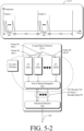
- the radar system 102 also includes at least one processing unit 212 and computer-readable storage media (CRM) 214.
- the CRM 214 includes a raw-data processing module 218 and a radar control module 220.
- the raw-data processing module 218 and the radar control module 220 can be implemented using hardware, software, firmware, or a combination thereof.
- the processing unit 212 executes instructions for implementing the raw-data processing module 218 and the radar control module 220.
- the raw-data processing module 218 and the radar control module 220 enable the processing unit 212 to process responses from the receive antenna elements in the antenna array 208 to detect the living object 108 and generate radar data for the vehicle-based systems 200.
- the raw-data processing module 218 transforms receiver signals including raw data (e.g., digital beat signals including baseband data) provided by the transceiver 210 into radar data (e.g., an amplitude as a function of range) that is usable by the radar control module 220.
- the radar control module 220 analyzes the radar data obtained over time to map one or more detections, e.g., of living objects.
- the radar control module 220 determines whether a living object 108 is present within the field-of-view 104 using a living-object detector 222 and optionally, an adaptive-threshold adjuster 224.
- the living-object detector 222 causes the radar control module 220 to operate in an occupant-detection mode where the radar signal 112 is analyzed for signs of living objects obscured by (e.g., thermal) noise.
- the living-object detector 222 determines a standard deviation between multiple frames to isolate stationary living objects, which move even if only to breath, from non-living objects, which remain mostly stationary from one frame to the next.
- the living-object detector 222 uses a noise threshold to determine whether the standard deviation at a particular range from the radar system 102 is a living object.
- the noise threshold is set to ensure that the movement is sufficient to indicate presence of a living object. Using the noise threshold, the radar system 102 can differentiate between a living object and either a stationary object or thermal noise produced by the radar system 102.
- the living-object detector 222 may determine a respective amplitude as a function of range for each of M plurality of frames by applying a Fourier transform, such as an FFT, to respective receiver signals of the N chirps in each frame.
- a Fourier transform such as an FFT
- the living-object detector 222 applies a Fourier transform to the receiver signal of each chirp in each frame.
- the results of each of the Fourier transforms are integrated over frames, using non-coherent integration (NCI).
- NCI non-coherent integration
- a standard deviation of the amplitude as a function of range between two or more of the plurality of frames is determined by integrating, using non-coherent integration, results of the Fourier transform applied to the respective receiver signal of each new frame M, with the standard deviation in amplitude over the previously received, plurality of frames 1 through ( M - 1).
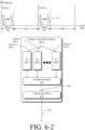
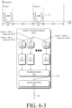
- the adaptive-threshold adjuster 224 is an optional component of the radar system 102.
- the living-object detector 222 may rely on the adaptive-threshold adjuster 224 to set the noise threshold used by the living-object detector 222 while the radar system 102 is operating in the occupant-detection mode.
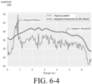
- the adaptive-threshold adjuster 224 automatically sets the noise threshold used, by the radar system 102, to detect a living object by accounting for the environmental changes. For example, during power-on, the radar signal 112 may undergo power drift until settling down to a normal level. As the effects of power drift become less, the adaptive-threshold adjuster 224 modifies the noise threshold settle to a nominal level. Over time, as the environment continues to change, the adaptive-threshold adjuster 224 increases and decreases the noise threshold with changes in noise levels, smoothing changes to the noise threshold between sequential frames.
- the radar control module 220 produces the radar data for the vehicle-based system 200.
- Example types of radar data include a Boolean value that indicates whether or not the object 108 is present within a particular region of interest, a number that represents a characteristic of the object 108 ( e.g., position, speed, or direction of motion), or a value that indicates the type of object 108 detected ( e.g., a living or non-living).
- the radar control module 220 configures the transceiver 210 to emit radar signals and detect radar reflections via the antenna array 208.
- the radar control module 220 outputs information associated with the radar reflections detected from radar signals that reach objects, such as the object 108.
- FIG. 3 illustrates an example operation 300 of the radar system 102.
- the living object 108 is located at a particular slant range and angle from the antenna array of the radar system 102.
- the radar system 102 transmits and receives a radar signal 112-1, which is an example of a frame 308 of the radar signal 112.
- the radar signal 112-1 is transmitted as a radar transmit signal 302.
- At least a portion of the radar transmit signal 302 is reflected by the living object 108. This reflected portion represents a radar reflection or a radar receive signal 304.
- the radar system processes the radar receive signal 304 to extract data for a vehicle-based system, such as the vehicle-based systems 200.
- an amplitude of the radar receive signal 304 is smaller than an amplitude of the radar transmit signal 302 due to losses incurred during propagation and reflection.
- the radar transmit signal 302 is illustrated as having a single waveform, the radar transmit signal 302 can be composed of multiple radar transmit signals 302 that have distinct waveforms to support MIMO operations.
- the radar receive signal 304 can be composed of multiple radar receive signals 302 that also have different waveforms.
- the radar transmit signal 302 includes one or more chirps 306-1 to 306-N, where N represents a positive integer.
- the radar system 102 can transmit the chirps 306-1, 306-2, ..., 306-N (collectively "the chirps 306") in a continuous sequence or transmit the chirps as time-separated pulses.
- the radar transmit signal 302 can include a quantity of M frames 308, where M represents a positive integer.
- Individual frequencies of the chirps 306 can increase or decrease over time, but the slope or rate of change in the individual frequencies between the chirps 306 can be consistent.
- the radar system 102 employs a single-slope cycle to linearly decrease the frequencies of the chirps 306 over time.
- Other types of frequency modulations are also possible, including a two-slope cycle and/or a non-linear frequency modulation.
- transmission characteristics of the chirps 306 e.g., bandwidth, center frequency, duration, and transmit power
- the radar receive signal 304 represents a delayed version of the radar transmit signal 302.
- the amount of delay is proportional to the slant range (e.g., distance) from the antenna array 208 of the radar system 102 to the living object 108.
- this delay represents a summation of a time it takes for the radar transmit signal 302 to propagate from the radar system 102 to the living object 108 and a time it takes for the radar receive signal 304 to propagate from the living object 108 to the radar system 102. If the living object 108 and/or the radar system 102 is moving, the radar receive signal 304 is shifted in frequency relative to the radar transmit signal 302 due to the Doppler effect.
- characteristics of the radar receive signal 304 are dependent upon motion of the living object 108 and/or motion of the vehicle 100. Similar to the radar transmit signal 302, the radar receive signal 304 is composed of one or more of the chirps 306. The chirps 306 enable the radar system 102 to make multiple observations of the object living 108 over a first time period during each of the frames 308.
- the radar signal 112-1 is based on a waveform structure with a combination of fast chirps and very slow chirps (or idle time) in each frame 308.
- the fast chirps 306 are followed by an idle period.
- the waveform includes N fast chirps 306 during a repetition period of a few microseconds. After the N fast chirps 306, a long idle period of the waveform precedes the start of the next frame 308. The idle period may be as long as 100 milliseconds.
- Each set of N fast chirps 306 in combination with the idle period forms a slow frame 308.
- the transceiver 210 accepts a control signal from the processing unit 212. Using the control signal, the processing unit 212 directs the transceiver 210 to operate in a particular configuration or operational mode, such as an occupant-detection mode. As an example, the control signal can specify types of waveforms to be generated by the transmit channels of the transceiver 210.
- Different waveform types can have a different N quantity of chirps 306, M quantity of frames 308, chirp durations, frame durations, center frequencies, bandwidths, types of frequency modulation (e.g., a single-slope modulation, a two-slope modulation, a linear modulation, or a non-linear modulation), or types of phase modulations (e.g., different orthogonal coding sequences).
- the control signal can specify which transmit channels are enabled or disabled. In the example of FIG. 3 , the control signal specifies the characteristics of the radar signal 112-1 as having a quantity of N chirps 306, a recurring idle time at the end of each frame 308, and a total quantity of M frames 308.
- the transceiver 210 Based on the control signal, the transceiver 210 generates a frequency-modulated radar signal 112-1 at radio frequencies on the transmit channels.
- a phase modulator of the transceiver 210 may modulate phases of chirps within the frequency-modulated radar signal to generate a frequency-modulated and phase-modulated radar signal in cases where phase-modulation is used.
- the phases of the chirps 306 can be determined based on a coding sequence specified by the control signal.
- the control signal directs the transceiver 210 to transmit a FMCW radar signal and in return receive FMCW radar reflections from objects in the field-of-view 104.
- the receive antenna elements of the antenna array 208 receive a version of a radar receive signal 304. Relative phase differences between these versions of the radar receive signal 304 are due to differences in locations of the receive antenna elements and the transmit antenna elements of the antenna array 208.
- a mixer performs a beating operation, which down-converts and demodulates the radar receive signals 304 to generate corresponding beat signals.
- a frequency of a beat signal for a chirp pattern that relies on a chirp pattern with a single chirp 306 between each idle period corresponds to a difference in frequency between the radar transmit signal 302 and the radar receive signal 304. This frequency difference is proportional to a slant range between the antenna array 208 and the object 108.
- the beat signal for each frame 308 represents a combination of the beat signals for some or all of the chirps 306 within each frame 308.
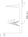
- FIG. 4-1 illustrates amplitudes, as a function of range, of multiple radar signals received by an example FMCW radar system.
- the radar system 102 receives radar signals 112-2 through 112-6, which are each an example of a frame 308 of the radar signal 112.
- the radar system 102 determines amplitudes of the radar signals 112-2 through 112-6 as a function of range.
- Each of the radar signals 112-2 through 112-6 is unique to a single frame 308.
- the peak amplitude of each of the radar signals 112-2 through 112-6 decreases from one signal to the next.
- the change in amplitude across a sequence of frames 308 at the range 402 indicates movement at the range 402.
- the amplitude of the radar signals 112-2 through 112-6 remains consistent from one frame 308 to the next.
- Example 4 The radar system of any of the preceding examples, wherein the processing unit is configured to apply the Fourier transform to the multiple chirps by applying the Fourier transform to a common receiver signal for the multiple chirps in each frame over the plurality of frames.
- Example 14 The radar system of any of the preceding examples, wherein the standard deviation is a first standard deviation, wherein the processing unit is further configured to: direct the transceiver to generate, for a subsequent frame, the chirp pattern that has the first period of multiple chirps followed by the second period of idle time; determine, based in part on the first standard deviation and a respective amplitude as a function of range for the subsequent frame, a second standard deviation in the respective amplitude for the reflections within the subsequent frame and each of the plurality of frames; and in response to the second standard deviation not satisfying the noise threshold, refrain from outputting the indication of the object.
- the processing unit is further configured to: direct the transceiver to generate, for a subsequent frame, the chirp pattern that has the first period of multiple chirps followed by the second period of idle time; determine, based in part on the first standard deviation and a respective amplitude as a function of range for the subsequent frame, a second standard deviation in the respective amplitude for the reflections within the subsequent frame
- Example 19 A computer-readable storage medium comprising instructions that, when executed by a processing unit of a radar system, cause the processing unit to: direct a transceiver of the radar system to generate a plurality of frames of radar signals having a chirp pattern that has a first period of multiple chirps followed by a second period of idle time; apply a Fourier transform to respective reflections obtained during the first period of each of the plurality of frames to determine a respective amplitude of the reflections as a function of range for each of the plurality of frames; based on the respective amplitude of the reflections for each of the plurality of frames, determine a standard deviation in the respective amplitude for the reflections within each of the plurality of frames; and in response to the standard deviation in the respective amplitude for any of the reflections within the plurality of frames satisfying a noise threshold, output, an indication of a living object detected during the plurality of frames.
- Example 21 A radar system comprising: an antenna array; a transceiver configured to generate radar signals via the antenna array; and a processing unit configured to: direct the transceiver to generate, over a first plurality of frames, the radar signals having a chirp pattern that has a first period of multiple chirps followed by a second period of idle time; determine a respective amplitude as a function of range for the reflections obtained during each of the first plurality of frames; based on the respective amplitude for the reflections obtained during each of the plurality of frames, determine a baseline standard deviation in amplitude as a function of range for the first plurality of frames; adjust an adaptive noise threshold based on a dynamic noise response of the radar system by smoothing the baseline standard deviation for the first plurality of frames and setting the adaptive noise threshold to the baseline standard deviation after the smoothing; and responsive to a standard deviation in amplitude as a function of range for a second plurality of frames generated using the chirp pattern satisfying the adaptive noise threshold, output an indication of a living object detected
- Example 30 The radar system of any of the preceding examples, wherein the second period of idle time is longer than the first period of multiple chirps.
- Example 32 The radar system of any of the preceding examples, wherein the first period is approximately two or more microseconds and the second period is less than approximately 100 milliseconds.
- Example 33 The radar system of any of the preceding examples, wherein the processing unit is further configured to: direct the transceiver to generate the chirp pattern in a third frame after the second plurality of frames; determine, based on the standard deviation in amplitude for the second plurality of frames and an amplitude as a function of range for the third frame, a standard deviation in amplitude as a function of range for the third frame; and based on whether the standard deviation in amplitude for the third frame satisfies the adaptive noise threshold, output or refrain from outputting an indication of a living object detected during the third frame.
- Example 34 The radar system of any of the preceding examples, wherein the processing unit is further configured to: smooth the standard deviation in amplitude for the second plurality of frames; and set the adaptive noise threshold for the third frame to the smoothed, standard deviation in amplitude for the second plurality of frames.
- Example 35 The radar system of any of the preceding examples, wherein the processing unit is further configured to optionally add an offset to the smoothed, standard deviation in amplitude for the second plurality of frames before setting the adaptive noise threshold for the third frame to the smoothed, standard deviation for the second plurality of frames.
- Example 36 The radar system of any of the preceding examples, wherein the processing unit is further configured to: output the indication of the living object detected during the third frame in response to the standard deviation for the third frame satisfying the adaptive noise threshold.
- Example 37 The radar system of any of the preceding examples, wherein the processing unit is further configured to: determine a previous mean amplitude equal to a mean amplitude for the second plurality of frames; determine a current mean amplitude equal to the previous mean amplitude incremented by a fraction of the amplitude of the third frame, the fraction of the amplitude of the third frame being equal to a difference between the amplitude of the third frame and the previous mean amplitude, the difference being divided by a total quantity of frames among the second plurality of frames and the third frame; determine the standard deviation in amplitude for the third frame by incrementing the baseline standard deviation by an amount determined based on the amplitude of the third frame, the previous mean amplitude, and the current mean amplitude; and store the current mean amplitude as the previous mean amplitude for use in subsequently incrementing the current mean amplitude.
- Example 38 The radar system of any of the preceding examples, wherein the amount determined based on the range of the third frame, the previous mean, and the current mean is based on a product of the amplitude of the third frame minus the previous mean amplitude and the amplitude of the third frame minus the current mean amplitude.
- Example 39 A computer-readable storage medium comprising instructions that, when executed by a processing unit of a radar system, cause the processing unit to: direct a transceiver to generate, over a first plurality of frames, radar signals having a chirp pattern that has a first period of multiple chirps followed by a second period of idle time; determine a respective amplitude as a function of range for reflections of the radar signals obtained during each of the first plurality of frames; based on the respective amplitude for the reflections obtained during each of the plurality of frames, determine a baseline standard deviation in amplitude as a function of range for the first plurality of frames; adjust an adaptive noise threshold based on a dynamic noise response of the radar system by smoothing the baseline standard deviation for the first plurality of frames and setting the adaptive noise threshold to the baseline standard deviation after the smoothing; and responsive to a standard deviation in amplitude as a function of range for a second plurality of frames generated using the chirp pattern satisfying the adaptive noise threshold, output an indication of a living object detected during
- Example 40 A method comprising: generating, by a radar system, over a first plurality of frames, radar signals having a chirp pattern that has a first period of multiple chirps followed by a second period of idle time; determining, by the radar system, a respective amplitude as a function of range for reflections of the radar signals obtained during each of the first plurality of frames; based on the respective amplitude for the reflections obtained during each of the plurality of frames, determining, by the radar system, a baseline standard deviation in amplitude as a function of range for the first plurality of frames; adjusting, by the radar system, an adaptive noise threshold based on a dynamic noise response of the radar system by smoothing the baseline standard deviation for the first plurality of frames and setting the adaptive noise threshold to the baseline standard deviation after the smoothing; and responsive to a standard deviation in amplitude as a function of range for a second plurality of frames generated using the chirp pattern satisfying the adaptive noise threshold, outputting, by the radar system, an indication of a living object
- a radar system comprising: an antenna array; a transceiver configured to generate radar signals via the antenna array; and a processing unit configured to: direct the transceiver to generate a first plurality of frames of radar signals having a chirp pattern that has a first period of multiple chirps followed by a second period of idle time; apply a Fourier transform to reflections of the radar signals obtained within the first plurality of frames to determine a respective amplitude, as a function of range, for each of the first plurality of frames; determine a first standard deviation in amplitude for the first plurality of frames based on the respective amplitude determined for each of the first plurality of frames; store a previous mean amplitude equal to a mean amplitude for the first plurality of frames; direct the transceiver to generate the chirp pattern in a subsequent frame to the first plurality of frames; determine a current mean amplitude equal to the previous mean amplitude incremented by a fraction of an amplitude, as a function of range, of the
- Example 42 The radar system of any of the preceding examples, wherein the processing unit is further configured to: store the current mean amplitude as the previous mean amplitude for subsequently incrementing the current mean for another subsequent frame.
- Example 43 The radar system of any of the preceding examples, wherein the processing unit is further configured to: direct the transceiver to generate the chirp pattern in the other subsequent frame; determine the current mean amplitude being equal to the previous mean amplitude incremented by a fraction of an amplitude, as a function of range, of the other subsequent frame, the fraction of the amplitude of the other subsequent frame being equal to a difference between the amplitude of the other subsequent frame and the previous mean amplitude, the difference being divided by a total quantity of frames among the first plurality of frames, the subsequent frame, and the other subsequent frame; and determine a third standard deviation in amplitude for the first plurality of frames, the subsequent frame, and the other subsequent frame by incrementing the second standard deviation by a function of the range of the subsequent frame, the previous mean, and the current mean; and responsive to the third standard deviation satisfying the noise threshold, output an indication of a living object detected during the first plurality of frames, the subsequent frame, and the other subsequent frame.
- Example 44 The radar system of any of the preceding examples, wherein the function of the range of the subsequent frame, the previous mean amplitude, and the current mean amplitude is based on a product of the amplitude of the subsequent frame minus the previous mean amplitude and the amplitude of the subsequent frame minus the current mean amplitude.
- Example 45 The radar system of any of the preceding examples, wherein the processing unit is configured to apply the Fourier transform to the first plurality of frames by applying the Fourier transform to respective receiver signals of each of the multiple chirps in each frame.
- Example 46 The radar system of any of the preceding examples, wherein the processing unit is further configured to apply the Fourier transform to the first plurality of frames by integrating, using non-coherent integration, results of the applying the Fourier transform to the respective receiver signal of each chirp from the multiple chirps in each frame.
- Example 47 The radar system of any of the preceding examples, wherein the processing unit is configured to apply the Fourier transform to the first plurality of frames by applying the Fourier transform to a common receiver signal of the multiple chirps in each frame.
- Example 48 The radar system of any of the preceding examples, wherein the processing unit is configured to determine the common receiver signal of the multiple chirps in each frame by averaging the respective receiver signals of the multiple chirps in that frame.
- Example 49 The radar system of any of the preceding examples, wherein the processing unit is configured to determine the common receiver signal of the multiple chirps in each frame by summing the respective receiver signals of the multiple chirps in that frame.
- Example 50 The radar system of any of the preceding examples, wherein the second period of idle time is longer than the first period of multiple chirps.
- Example 51 The radar system of any of the preceding examples, wherein the processing unit is further configured to determine the first standard deviation for the first plurality of frames or the mean amplitude for the first plurality of frames by compensating for false triggers to detections resulting from power drift of the radar system.
- Example 52 The radar system of any of the preceding examples, wherein the processing unit is further configured to incrementally compensate for the false triggers to detections resulting from the power drift.
- Example 53 The radar system of any of the preceding examples, wherein the noise threshold is a predetermined threshold based on radar characteristics of the radar system.
- Example 54 The radar system of any of the preceding examples, wherein the noise threshold is an adaptive noise threshold and the processing unit is further configured to adjust the adaptive noise threshold based on a dynamic noise response of the radar system.
- the noise threshold is an adaptive noise threshold and the processing unit is further configured to adjust the adaptive noise threshold based on a dynamic noise response of the radar system.
- Example 55 The radar system of any of the preceding examples, wherein the first standard deviation is a baseline standard deviation and the processing unit is further configured to: determine the adaptive noise threshold by smoothing the baseline standard deviation and setting the adaptive noise threshold to the baseline standard deviation.
- Example 56 The radar system of any of the preceding examples, wherein the processing unit is further configured to optionally add an offset to the baseline standard deviation after smoothing the baseline standard deviation to determine the adaptive noise threshold.
- Example 57 The radar system of any of the preceding examples, wherein the processing unit is further configured to: direct the transceiver to generate the chirp pattern in another subsequent frame following the subsequent frame; determine, based in part on the second standard deviation and a respective amplitude for the other subsequent frame, a third standard deviation; and in response to the third standard deviation not satisfying the noise threshold, refrain from outputting an indication of an object detected in the other subsequent frame.
- Example 58 The radar system of any of the preceding examples, wherein the transceiver includes a transmitter and the receiver.
- Example 59 A computer-readable storage medium comprising instructions that, when executed by a processing unit of a radar system, cause the processing unit to: direct a transmitter and a receiver of the radar system to generate a first plurality of frames of radar signals having a chirp pattern that has a first period of multiple chirps followed by a second period of idle time; apply a Fourier transform to reflections of the radar signals obtained within the first plurality of frames to determine a respective amplitude, as a function of range, for each of the first plurality of frames; determine a first standard deviation in amplitude for the first plurality of frames based on the respective amplitude determined for each of the first plurality of frames; store a previous mean amplitude equal to a mean amplitude for the first plurality of frames; direct the transceiver to generate the chirp pattern in a subsequent frame to the first plurality of frames; determine a current mean amplitude equal to the previous mean amplitude incremented by a fraction of an amplitude, as a function of range
- Example 60 A method comprising: generating, by a radar system, a first plurality of frames of radar signals having a chirp pattern that has a first period of multiple chirps followed by a second period of idle time; applying a Fourier transform to reflections of the radar signals obtained within the first plurality of frames to determine a respective amplitude, as a function of range, for each of the first plurality of frames; determining a first standard deviation in amplitude for the first plurality of frames based on the respective amplitude determined for each of the first plurality of frames; storing, by the radar system, a previous mean amplitude equal to a mean amplitude for the first plurality of frames; generating, by the radar system, the chirp pattern in a subsequent frame to the first plurality of frames; determining a current mean amplitude equal to the previous mean amplitude incremented by a fraction of an amplitude, as a function of range, of the subsequent frame, the fraction of the range of the subsequent frame being equal to a difference between
Landscapes
- Engineering & Computer Science (AREA)
- Radar, Positioning & Navigation (AREA)
- Remote Sensing (AREA)
- Physics & Mathematics (AREA)
- Computer Networks & Wireless Communication (AREA)
- General Physics & Mathematics (AREA)
- Electromagnetism (AREA)
- Signal Processing (AREA)
- Radar Systems Or Details Thereof (AREA)
Abstract
Description
- Various sensors are available as occupant detectors within vehicles. Radar is particularly suited for detecting even the most difficult-to-detect living objects, such as passengers who are asleep or remain still. Vital signs (e.g., heartbeat signals, respiration signals) of an infant sleeping under a blanket and/or in a car seat have distinct radar signatures. Frequency-modulated continuous-wave (FMCW) radar systems, with long integration times and small duty cycles, can isolate subtle signal variations introduced by a sleeping child from signal variations introduced by noise and other objects in the field of view, which are not similar to the subtle signal variations introduced by a sleeping child. Thermal noise generated by an FMCW radar can easily mask the subtle signal variations in amplitude introduced over time by stationary living objects; the radar cross-section of a living object, especially a small child at a sedentary condition (e.g., sleeping), is much smaller than, and therefore can easily be masked by, the radar cross-sections of other objects inside the vehicle. The radar cross-section is a measure of how detectable an object is by radar. A larger radar cross-section indicates that an object is more easily detected. Radar reflections that are indicative of a small child's heartbeat or respiration can be indistinguishable from thermal noise.
- One way to improve the distinction is by increasing the signal-to-noise ratio (SNR) between radar reflections from living objects and radar reflections from non-living objects (including noise) by increasing the radiation power of the FMCW radar, which aside from using more electrical power, may raise some health concerns. Another way to increase the SNR is to increase the duty cycle of the FMCW radar and apply Fourier transforms to the radar reflections to distinguish the reflections caused by living objects from the reflections caused by stationary objects or noise. This, however, comes at the expense of significantly increasing the computational load and power consumption of the FMCW radar.
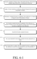
- The techniques of this disclosure enable frequency-modulated continuous-wave (FMCW) radar-based detection of living objects. Instead of generating a typical chirp pattern with individual chirps separated by long idle periods, a radar transceiver generates a multiple-chirp pattern with groupings of multiple chirps separated by long idles periods, for each frame. A frame being a duration of time during which the chirp pattern that has a first period of multiple chirps followed by a second period of idle time. From applying a Fourier transform (e.g., a fast Fourier transform, or "FFT") to receiver signals (e.g., digital beat signals including baseband data) for each frame, the radar determines an amplitude of the receiver signals, as a function of range, for each frame. The radar system computes the standard deviation between the amplitudes of two frames and, for each additional frame, the radar incrementally updates the standard deviation between the amplitudes of the two frames to be inclusive of the amplitude contribution of the additional frame. That is, rather than recalculate the standard deviation from scratch in response to each new frame, the radar system "incrementally" adjusts the previous standard deviation by a fraction of the amplitude of the new frame, which is proportionate to the total quantity of frames generated thus far. In response to the adjusted standard deviation satisfying a noise threshold, the radar outputs an indication of a living object. The techniques of this disclosure enable radar-based detection of living objects with an improved signal-to-noise ratio and therefore greater accuracy when compared to conventional FMCW radar systems. Live object detection is improved by the described systems and techniques without increasing radiation power, power consumption, costs, or computational load relative to a conventional FMCW radar system.
- In some aspects, a FMCW radar system includes an antenna array, a transceiver configured to generate radar signals via the antenna array, and a processing unit. In one example, the processing unit is configured to direct the transceiver to detect objects by generating, over a plurality of frames, the radar signals having a chirp pattern that has a first period of multiple chirps followed by a second period of idle time. The processing unit applies a Fourier transform to reflections of the radar signals obtained within each of the plurality of frames to determine a respective amplitude, as a function of range, for each of the plurality of frames, and based on the respective amplitude for each of the plurality of frames, determines a standard deviation in the amplitude as a function of range for the plurality of frames. The processing unit is further configured to, in response to the standard deviation in the amplitude for the plurality of frames satisfying a noise threshold, output an indication of a living object detected during the plurality of frames.
- In another example, the processing unit is configured to direct the transceiver to detect objects by generating, for a first plurality of frames, radar signals having a chirp pattern that has a first period of multiple chirps followed by a second period of idle time, determine a respective amplitude as a function of range for each of the first plurality of frames, and determine a baseline standard deviation in the amplitude for the first plurality of frames based on the respective amplitude determined for each of the first plurality of frames. The processing unit is further configured to adjust an adaptive noise threshold based on a dynamic noise response of the radar system by smoothing the baseline standard deviation in the amplitude and setting the adaptive noise threshold to the baseline standard deviation in amplitude. The processing unit is further configured to, responsive to a standard deviation in amplitude as a function of range for a second plurality of frames generated using the chirp pattern satisfying the adaptive noise threshold, output an indication of a living object detected during the second plurality of frames.
- In a further example, the processing unit is configured to direct the transceiver to detect objects by generating, for a first plurality of frames, radar signals having a chirp pattern that has a first period of multiple chirps followed by a second period of idle time. The processing unit determines a respective amplitude as a function of range for each of the first plurality of frames and determines a first standard deviation for the first plurality of frames based on the respective amplitude determined for each of the first plurality of frames. The processing unit is further configured to store, in a memory, a previous mean amplitude equal to a mean amplitude as a function of range for the first plurality of frames, direct the transceiver to generate the chirp pattern in a subsequent frame to the first plurality of frames, and determine a current mean amplitude equal to the previous mean amplitude adjusted by a fraction of an amplitude, as a function of range, of the subsequent frame. The fraction of the amplitude of the subsequent frame is equal to a difference between the amplitude of the subsequent frame and the previous mean amplitude, the difference being divided by a total quantity of frames among the first plurality of frames and the subsequent frame. The processing unit is further configured to determine a second standard deviation in amplitude as a function of range of the first plurality of frames and the subsequent frame by adjusting the first standard deviation in amplitude by an amount based on the amplitude of the subsequent frame, the previous mean amplitude, and the current mean amplitude. Responsive to the second standard deviation satisfying a noise threshold, the processing unit outputs an indication of a living object detected during the first plurality of frames and the subsequent frame.
- This document also describes computer-readable media having instructions for performing methods by the above-summarized FMCW radar systems. Other FMCW radar systems, computer-readable media, and methods are set forth herein, as well as systems and means for performing the aforementioned methods, which are further described below.
- This summary is provided to introduce simplified concepts for FMCW radar detection of living objects, which is further described below in the Detailed Description and Drawings. For ease of description, the disclosure focuses on vehicle-based or automotive-based radar systems for detecting passengers as the living objects, such as children or infants sleeping in car seats. However, the techniques and systems described herein are not limited to vehicle or automotive contexts, but also apply to other environments where radar can be used to detect living objects amongst noise. This summary is not intended to identify essential features of the claimed subject matter, nor is it intended for use in determining the scope of the claimed subject matter.
- The details of one or more aspects of FMCW radar-based detection of living objects are described in this document with reference to the following drawings. The same numbers are used throughout the drawings to reference like features and components:
-
FIG. 1 illustrates an example vehicle in which an example FMCW radar system can detect living objects. -
FIG. 2 illustrates an example implementation of a FMCW radar system as part of a vehicle. -
FIG. 3 illustrates an example operation of an example FMCW radar system. -
FIG. 4-1 illustrates an amplitude, as a function of range, of a radar signal from an example FMCW radar system. -
FIG. 4-2 illustrates a standard deviation of the amplitudes fromFIG. 4-2 . -
FIG. 5-1 illustrates example operations performed by an FMCW radar system. -
FIGS. 5-2 and5-3 illustrate different examples of living-object detectors of an FMCW radar system. -
FIG. 5-4 illustrates examples of a standard deviation in an amplitude of radar reflections, as a function of range, determined by the living-object detectors ofFIG. 5-2 andFIG. 5-3 , in contrast to a standard deviation in an amplitude of a conventional radar system. -
FIG. 6-1 illustrates example operations performed by an FMCW radar system. -
FIGS. 6-2 and6-3 illustrate different examples of adaptive-threshold adjusters of an FMCW radar system. -
FIG. 6-4 illustrates an example adaptive threshold during part of a frame generated by an FMCW radar system that uses the example adaptive-threshold adjusters ofFIG. 6-2 orFIG. 6-3 . -
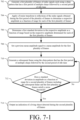
FIG. 7-1 illustrates example operations performed by an FMCW radar system. -
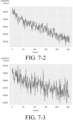
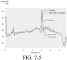
FIGS. 7-2 through 7-4 illustrate an example of power drift in an FMCW radar system. -
FIG. 7-5 illustrates an example adaptive threshold during part of a frame generated by an FMCW radar system that corrects for power drift. - The details of one or more aspects of radar-based detection of living objects are described below. With long integration times and small duty cycles, conventional FMCW radar systems are particularly suited for identifying subtle variations in radar reflections introduced by mostly stationary living objects from among variations in radar reflections introduced by other, non-living objects. However, thermal noise generated by the radar, as well as noise from other sources, can obscure the radar cross-section (RCS) of a human body, especially the body of a small child, which can make detecting living objects difficult or unreliable.
- In contrast to these conventional FMCW radar systems, this document describes a more-reliable FMCW radar system for use as a living-object detector. In accordance with techniques of this disclosure, a FMCW radar system uses an atypical (multiple) chirp pattern for each frame. This increases the signal-to-noise ratio (SNR) between amplitudes of reflections from objects that are alive, and amplitudes of reflections from non-living objects and noise, including thermal noise from the radar itself. For example, the motion pattern from other objects are generally, not similar to the periodicity and amplitude of a moving chest wall of a child. The SNR is increased without increasing radiation power, which aside from preserving electrical power, may reduce some health concerns. The example FMCW radar system increases the SNR without increasing computational load, power consumption, or cost.
- Instead of a typical chirp pattern with individual chirps separated by a long idle period, the radar system generates, for a plurality of frames, a repeating-multiple chirp pattern that has a first period of multiple chirps and a second, lengthier period of idle time for each frame. The period of idle time can be orders of a magnitude longer than the first period of the frame. From applying a Fourier transform to individual or averaged receiver signals (e.g., digital beat signals including baseband data) determined from reflections obtained during the plurality of frames, the FMCW radar system determines a respective amplitude, as a function of range, for each of the plurality of frames. From the respective amplitude for each of the plurality of frames, the FMCW radar system computes a standard deviation of the amplitude for the plurality of frames. The FMCW may incrementally update the standard deviation, as a function of range, as each new frame is generated. That is, rather than recalculate the standard deviation each time a new frame is generated, the FMCW radar system can adjust the standard deviation by an amount proportional to the individual contribution of the amplitude of the new frame relative to the standard deviation of the previous frames.
- In response to the standard deviation of the amplitude satisfying a noise threshold, the FMCW radar system outputs an indication of a living object detected during the plurality of frames. The FMCW radar system may rely on a predetermined threshold, set to a predetermined level based on observed characteristics of the FMCW radar system. In other examples, the FMCW radar system uses an adaptive noise threshold that changes according to a dynamic noise response of the radar system, including, compensating for power drift in the amplitude of the receiver signals, particularly during power-up. The techniques of this disclosure enable FMCW radar-based detection of living objects with an improved signal to noise ratio and therefore greater accuracy when compared to other radar-based detection systems.
-
FIG. 1 illustrates avehicle 100 in which an exampleFMCW radar system 102 can detect living objects, e.g., human and animal living occupants. Although illustrated as a car, thevehicle 100 can represent other types of motorized vehicles (e.g., a motorcycle, a bus, a tractor, a semi-trailer truck, or construction equipment), types of non-motorized vehicles (e.g., a bicycle), types of railed vehicles (e.g., a train or a trolley car), watercraft (e.g., a boat or a ship), aircraft (e.g., an airplane or a helicopter), or spacecraft (e.g., satellite). - The FMCW radar system 102 (referred to simply as "the
radar system 102") is mounted to, or integrated within, thevehicle 100. The techniques and systems described herein are not limited to vehicles or automotive contexts, but also apply to other mobile and non-mobile environments (e.g., residential or commercial heating and cooling systems, lighting systems, security systems) where live-object-detection may be useful, including machinery, robotic equipment, buildings and other structures. - The
radar system 102 is capable of detecting one or more objects that are within proximity to thevehicle 100. Specifically, theradar system 102 is configured for interior, as opposed to exterior, vehicle sensing. Theradar system 102 is configured to detect signs of life from objects that are alive and inside thevehicle 100. - In the depicted implementation, the
radar system 102 is located inside thevehicle 100 near the ceiling. In other implementations, theradar system 102 can be mounted in other parts of thevehicle 100. Theradar system 102 transmits radar signals and receives radar reflections in a portion of thevehicle 100 that is encompassed by a field-of-view 104. The field-of-view 104 includes one or more areas occupied by passengers or other living occupants of thevehicle 100. A livingobject 108, which may sometimes be referred to as a living target, is seated in a front or rear passenger seat, which is within the field-of-view 104. - The
radar system 102 is shown having three different parts positioned at different locations of thevehicle 100. Theradar system 102 can include additional or fewer parts in some implementations. Sometimes referred to as modules or radar systems themselves, the parts of theradar system 102 can be designed and positioned to provide a particular field ofview 104 that encompasses a specific region of interest. Example fields ofview 104 include a 360-degree field of view, one or more 180-degree fields of view, one or more 90-degree fields of view, and so forth, which can overlap (e.g., for creating a particular size field of view). The livingobject 108 is an infant in a car seat. The livingobject 108 can be any other human or animal occupant that reflects radar signals. Theradar system 102 and thevehicle 100 are further described with respect toFIG. 2 . - In general, the
radar system 102 is configured to detect theliving object 108 by generating, over a plurality of frames, a chirp pattern that has a first period of multiple chirps followed by a second period of idle time for each frame. For example, aradar signal 112 is shown inFIG. 1 which includes the chirp pattern described, where in each frame, theradar signal 112 includes a repeating pattern of two or more chirps followed by an idle period where theradar signal 112 remains silent until the next frame. The period of idle time is longer than the period of multiple chirps. For example, the first period of each frame with the multiple chirps is approximately two or more microseconds and the second period is less than approximately 100 milliseconds. - The
radar system 102 is configured to apply a Fourier transform to the reflected signals corresponding to the pattern of multiple chirps within each of the plurality of frames of theradar signal 112. Using results obtained from application of the transformation, theradar system 102 is configured to determine a respective amplitude, as a function of range, for each of the plurality of frames. From the respective amplitudes, theradar system 102 is configured to determine a standard deviation in the amplitude, as a function of range, for the frames of theradar signal 112. - The
radar system 102 may incrementally update the standard deviation in the amplitude, as each frame is generated. For example, rather than recalculate the standard deviation each time a new frame is generated, theradar system 102 is configured to adjust the standard deviation by a fraction of the amplitude for the new frame. The fraction of the amplitude is proportional to the individual contribution of the new frame relative to the contribution of the previous frames. - The
radar system 102 operates according to a noise threshold. In some examples, the noise threshold is an adaptive threshold that adjusts over time. By adjusting the noise threshold based on changes to a dynamic noise response of theradar system 102, including by compensating for power drift in the amplitude of theradar signal 112, particularly during power-up, theradar system 102 can more accurately detect living objects. - In response to the standard deviation satisfying the noise threshold, the
radar system 102 is configured to output an alert or other indication of theliving object 108 detected during the plurality of frames of theradar signal 112. For example, the field-of-view 104 includes one or more areas occupied by passengers of thevehicle 100 and the radar system outputs an indication of livingobject 108 detected in thevehicle 100. A processing unit of theradar system 102 outputs the indication of theliving object 108 to an alert system, which in response, outputs an audible, visual, or haptic feedback to a human or machine about an occupant inside an unattended vehicle. The alert system may provide an alarm monitoring service which notifies the owner(s) of thevehicle 100 via telephone and if unsuccessful in contacting the owner, contacts help (e.g., local police, fire, or ambulance services). In response to the indication of theliving object 108, the alert system may take action, for example, by directing thevehicle 100 to heat, cool, or ventilate the interior of thevehicle 100 in response to receiving an indication of theliving object 108. - The atypical chirp pattern of the radar signal includes a chirp pattern having multiple chirps, instead of a chirp pattern that includes a single chirp which proceeds each idle period of the chirp pattern generated by the
radar system 102. The atypical chirp pattern of the radar signal increases the SNR between radar reflections detected from living objects and other radar reflections detected from stationary objects and noise. The SNR is increased without increasing radiation power of theradar system 102, which aside from preserving electrical power, may reduce some health concerns related to operating theradar system 102 near the livingobject 108 or other occupants of thevehicle 100. Theradar system 102 thus increases the SNR without increasing computational load, power consumption, or cost. -
FIG. 2 illustrates an example implementation of theradar system 102 as part of thevehicle 100. Thevehicle 100 includes vehicle-basedsystems 200 that rely on data from theradar system 102, such as anoccupancy detector system 202 and an autonomous driving system 204. Generally, the vehicle-basedsystems 200 use radar data provided by theradar system 102 to perform a function. For example, the autonomous driving system 204 takes control of thevehicle 100 in response to theradar system 102 detecting a sleeping driver to bring the vehicle safely to a stop. Theoccupancy detector 202 sounds an alarm of thevehicle 100 and/or ventilates thevehicle 100 in response to theradar system 102 detecting a child or pet inadvertently left in thevehicle 100, unattended. - The
radar system 102 includes acommunication interface 206 to transmit the radar data to the vehicle-basedsystems 200 or to another component of thevehicle 100 over a communication bus of thevehicle 100, for example, when the individual components shown in theradar system 102 are integrated, including at different positions or locations, within thevehicle 100. In general, the radar data provided by thecommunication interface 206 is in a format usable by the vehicle-basedsystems 200. Thecommunication interface 206 may provide information to theradar system 102, such as the speed of thevehicle 100, the interior temperature of the of thevehicle 100, etc. Theradar system 102 can use this information to appropriately configure itself. For example, theradar system 102 can enter "occupant-detection mode" where theradar system 102 configures itself to generate each frame with a multiple chirp pattern in response to receiving an indication that thevehicle 100 is parked and/or an internal temperature is above or nearing an unsafe temperature for human or animal occupants. - The
radar system 102 also includes at least oneantenna array 208 and atransceiver 210 to transmit and receive radar signals. Theantenna array 208 includes a transmit antenna element, for example, one per each transmit channel. A receive antenna element of theantenna array 208 is coupled to each receive channel to receive radar reflections in response to the radar signals. Theantenna array 208 can include multiple transmit antenna elements and multiple receive antenna elements to configure theradar system 102 as a MIMO (Multiple Input Multiple Output) radar system capable of transmitting multiple distinct waveforms at a given time (e.g., a different waveform per transmit antenna element). The antenna elements can be circularly polarized, horizontally polarized, vertically polarized, or a combination thereof. - Using the
antenna array 208, theradar system 102 can form beams that are steered or un-steered, and wide or narrow. The steering and shaping can be achieved through analog beamforming or digital beamforming. The one or more transmitting antenna elements can have an un-steered omnidirectional radiation pattern, or the one or more transmitting antenna elements can produce a wide steerable beam to illuminate a large volume of space. To achieve object angular accuracies and angular resolutions, the receiving antenna elements can be used to generate hundreds of narrow steered beams with digital beamforming. In this way, theradar system 102 can efficiently monitor an external or internal environment of thevehicle 100 to detect one or more objects within the field-of-view 104. - The
transceiver 210, which may include multiple transceivers, includes circuitry and logic for transmitting radar signals and receiving radar reflections (also sometimes referred to as radar receive signals or radar returns) via theantenna array 208. A transmitter of thetransceiver 210 includes one or more transmit channels and a receiver of thetransceiver 210 includes one or more receive channels, which may be of a similar or different quantity than a quantity of the transmit channels. The transmitter and receiver may share a local oscillator (LO) to synchronize operations. Thetransceiver 210 can also include other components not shown, such as amplifiers, mixers, phase shifters, switches, analog-to-digital converters, combiners, and the like. - The
transceiver 210 is primarily configured as a continuous-wave transceiver 210 to execute FMCW operations, and may also include logic to perform in-phase/quadrature (I/Q) operations and/or modulation or demodulation in a variety of ways, including linear-frequency modulations, triangular-frequency modulations, stepped-frequency modulation, or phase modulation. Thetransceiver 210 may be configured to support pulsed-radar operations, as well. - A frequency spectrum (e.g., range of frequencies) of radar signals and radar reflections can encompass frequencies between one and ten gigahertz (GHz), as one example. The bandwidths can be less than one GHz, such as between approximately three hundred megahertz (MHz) and five hundred MHz. The frequencies of the
transceiver 210 may be associated with millimeter wavelengths. - The
radar system 102 also includes at least oneprocessing unit 212 and computer-readable storage media (CRM) 214. TheCRM 214 includes a raw-data processing module 218 and aradar control module 220. The raw-data processing module 218 and theradar control module 220 can be implemented using hardware, software, firmware, or a combination thereof. In this example, theprocessing unit 212 executes instructions for implementing the raw-data processing module 218 and theradar control module 220. Together, the raw-data processing module 218 and theradar control module 220 enable theprocessing unit 212 to process responses from the receive antenna elements in theantenna array 208 to detect theliving object 108 and generate radar data for the vehicle-basedsystems 200. - The raw-
data processing module 218 transforms receiver signals including raw data (e.g., digital beat signals including baseband data) provided by thetransceiver 210 into radar data (e.g., an amplitude as a function of range) that is usable by theradar control module 220. Theradar control module 220 analyzes the radar data obtained over time to map one or more detections, e.g., of living objects. Theradar control module 220 determines whether aliving object 108 is present within the field-of-view 104 using a living-object detector 222 and optionally, an adaptive-threshold adjuster 224. - The living-
object detector 222 causes theradar control module 220 to operate in an occupant-detection mode where theradar signal 112 is analyzed for signs of living objects obscured by (e.g., thermal) noise. The living-object detector 222 determines a standard deviation between multiple frames to isolate stationary living objects, which move even if only to breath, from non-living objects, which remain mostly stationary from one frame to the next. The living-object detector 222 uses a noise threshold to determine whether the standard deviation at a particular range from theradar system 102 is a living object. The noise threshold is set to ensure that the movement is sufficient to indicate presence of a living object. Using the noise threshold, theradar system 102 can differentiate between a living object and either a stationary object or thermal noise produced by theradar system 102. - The living-
object detector 222 may determine a respective amplitude as a function of range for each of M plurality of frames by applying a Fourier transform, such as an FFT, to respective receiver signals of the N chirps in each frame. In processing theradar signal 112, for example, the living-object detector 222 applies a Fourier transform to the receiver signal of each chirp in each frame. The results of each of the Fourier transforms are integrated over frames, using non-coherent integration (NCI). The living-object detector 222 determines a respective amplitude as a function of range for each of the M plurality of frames. A standard deviation of the amplitude as a function of range between two or more of the plurality of frames is determined by integrating, using non-coherent integration, results of the Fourier transform applied to the respective receiver signal of each new frame M, with the standard deviation in amplitude over the previously received, plurality offrames 1 through (M - 1). - The adaptive-
threshold adjuster 224 is an optional component of theradar system 102. The living-object detector 222 may rely on the adaptive-threshold adjuster 224 to set the noise threshold used by the living-object detector 222 while theradar system 102 is operating in the occupant-detection mode. As the environment within thevehicle 100 changes, the adaptive-threshold adjuster 224 automatically sets the noise threshold used, by theradar system 102, to detect a living object by accounting for the environmental changes. For example, during power-on, theradar signal 112 may undergo power drift until settling down to a normal level. As the effects of power drift become less, the adaptive-threshold adjuster 224 modifies the noise threshold settle to a nominal level. Over time, as the environment continues to change, the adaptive-threshold adjuster 224 increases and decreases the noise threshold with changes in noise levels, smoothing changes to the noise threshold between sequential frames. - The
radar control module 220 produces the radar data for the vehicle-basedsystem 200. Example types of radar data include a Boolean value that indicates whether or not theobject 108 is present within a particular region of interest, a number that represents a characteristic of the object 108 (e.g., position, speed, or direction of motion), or a value that indicates the type ofobject 108 detected (e.g., a living or non-living). Theradar control module 220 configures thetransceiver 210 to emit radar signals and detect radar reflections via theantenna array 208. Theradar control module 220 outputs information associated with the radar reflections detected from radar signals that reach objects, such as theobject 108. -
FIG. 3 illustrates anexample operation 300 of theradar system 102. Within thevehicle 100, the livingobject 108 is located at a particular slant range and angle from the antenna array of theradar system 102. To detect theliving object 108, theradar system 102 transmits and receives a radar signal 112-1, which is an example of aframe 308 of theradar signal 112. The radar signal 112-1 is transmitted as a radar transmitsignal 302. At least a portion of the radar transmitsignal 302 is reflected by the livingobject 108. This reflected portion represents a radar reflection or a radar receivesignal 304. The radar system processes the radar receivesignal 304 to extract data for a vehicle-based system, such as the vehicle-basedsystems 200. As shown inFIG. 3 , an amplitude of the radar receivesignal 304 is smaller than an amplitude of the radar transmitsignal 302 due to losses incurred during propagation and reflection. - Although the radar transmit
signal 302 is illustrated as having a single waveform, the radar transmitsignal 302 can be composed of multiple radar transmitsignals 302 that have distinct waveforms to support MIMO operations. Likewise, the radar receivesignal 304 can be composed of multiple radar receivesignals 302 that also have different waveforms. - The radar transmit
signal 302 includes one or more chirps 306-1 to 306-N, where N represents a positive integer. Theradar system 102 can transmit the chirps 306-1, 306-2, ..., 306-N (collectively "thechirps 306") in a continuous sequence or transmit the chirps as time-separated pulses. Thechirps 306, when followed by a period of idle time, represent aframe 308. The radar transmitsignal 302 can include a quantity of M frames 308, where M represents a positive integer. - Individual frequencies of the
chirps 306 can increase or decrease over time, but the slope or rate of change in the individual frequencies between thechirps 306 can be consistent. In the depicted example, theradar system 102 employs a single-slope cycle to linearly decrease the frequencies of thechirps 306 over time. Other types of frequency modulations are also possible, including a two-slope cycle and/or a non-linear frequency modulation. In general, transmission characteristics of the chirps 306 (e.g., bandwidth, center frequency, duration, and transmit power) can be tailored to achieve a particular detection range, range resolution, or Doppler coverage for detecting theliving object 108. - At the
radar system 102, the radar receivesignal 304 represents a delayed version of the radar transmitsignal 302. The amount of delay is proportional to the slant range (e.g., distance) from theantenna array 208 of theradar system 102 to theliving object 108. In particular, this delay represents a summation of a time it takes for the radar transmitsignal 302 to propagate from theradar system 102 to theliving object 108 and a time it takes for the radar receivesignal 304 to propagate from the livingobject 108 to theradar system 102. If theliving object 108 and/or theradar system 102 is moving, the radar receivesignal 304 is shifted in frequency relative to the radar transmitsignal 302 due to the Doppler effect. In other words, characteristics of the radar receivesignal 304 are dependent upon motion of theliving object 108 and/or motion of thevehicle 100. Similar to the radar transmitsignal 302, the radar receivesignal 304 is composed of one or more of thechirps 306. Thechirps 306 enable theradar system 102 to make multiple observations of the object living 108 over a first time period during each of theframes 308. - Where the
radar system 102 is used to detect very slow motions, such as movements of a chest wall during respiration and heartbeat, amplitude of the radar receivesignals 304 within a few microseconds will not change much. The radar signal 112-1 is based on a waveform structure with a combination of fast chirps and very slow chirps (or idle time) in eachframe 308. The fast chirps 306 are followed by an idle period. The waveform includes N fast chirps 306 during a repetition period of a few microseconds. After the N fast chirps 306, a long idle period of the waveform precedes the start of thenext frame 308. The idle period may be as long as 100 milliseconds. Each set of N fast chirps 306 in combination with the idle period forms aslow frame 308. - The
operation 300 is further described in the context ofFIG. 2 . During transmission, thetransceiver 210 accepts a control signal from theprocessing unit 212. Using the control signal, theprocessing unit 212 directs thetransceiver 210 to operate in a particular configuration or operational mode, such as an occupant-detection mode. As an example, the control signal can specify types of waveforms to be generated by the transmit channels of thetransceiver 210. Different waveform types can have a different N quantity ofchirps 306, M quantity offrames 308, chirp durations, frame durations, center frequencies, bandwidths, types of frequency modulation (e.g., a single-slope modulation, a two-slope modulation, a linear modulation, or a non-linear modulation), or types of phase modulations (e.g., different orthogonal coding sequences). Additionally, the control signal can specify which transmit channels are enabled or disabled. In the example ofFIG. 3 , the control signal specifies the characteristics of the radar signal 112-1 as having a quantity of N chirps 306, a recurring idle time at the end of eachframe 308, and a total quantity of M frames 308. - Based on the control signal, the
transceiver 210 generates a frequency-modulated radar signal 112-1 at radio frequencies on the transmit channels. A phase modulator of thetransceiver 210, may modulate phases of chirps within the frequency-modulated radar signal to generate a frequency-modulated and phase-modulated radar signal in cases where phase-modulation is used. For example, the phases of thechirps 306 can be determined based on a coding sequence specified by the control signal. The control signal directs thetransceiver 210 to transmit a FMCW radar signal and in return receive FMCW radar reflections from objects in the field-of-view 104. - During reception, the receive antenna elements of the
antenna array 208 receive a version of a radar receivesignal 304. Relative phase differences between these versions of the radar receivesignal 304 are due to differences in locations of the receive antenna elements and the transmit antenna elements of theantenna array 208. Within each receive channel, a mixer performs a beating operation, which down-converts and demodulates the radar receivesignals 304 to generate corresponding beat signals. - A frequency of a beat signal for a chirp pattern that relies on a chirp pattern with a
single chirp 306 between each idle period corresponds to a difference in frequency between the radar transmitsignal 302 and the radar receivesignal 304. This frequency difference is proportional to a slant range between theantenna array 208 and theobject 108. The beat signal for eachframe 308 represents a combination of the beat signals for some or all of thechirps 306 within eachframe 308. -
FIG. 4-1 illustrates amplitudes, as a function of range, of multiple radar signals received by an example FMCW radar system. As depicted inFIG. 4-1 , theradar system 102 receives radar signals 112-2 through 112-6, which are each an example of aframe 308 of theradar signal 112. Theradar system 102 determines amplitudes of the radar signals 112-2 through 112-6 as a function of range. Each of the radar signals 112-2 through 112-6 is unique to asingle frame 308. At a range of 402, the peak amplitude of each of the radar signals 112-2 through 112-6 decreases from one signal to the next. The change in amplitude across a sequence offrames 308 at therange 402 indicates movement at therange 402. In contrast, at 404 and most other ranges, the amplitude of the radar signals 112-2 through 112-6 remains consistent from oneframe 308 to the next. A consistent amplitude betweenframes 308, e.g., at therange 404 and other ranges excluding therange 402, indicates a lack of movement at a particular range. - Due to radar-cross-section-decorrelation at certain ranges, the
radar system 102 detects enough amplitude variation. Decorrelation occurs when the observation of radar-cross-section is significantly changed by an alteration of time, frequency, or angle. Once a target moves about a range, geometry of a reflecting surface undergoes some changes and hence radar-cross-section-decorrelation occurs. This radar-cross-section-decorrelation is the source of amplitude variation for detecting a living object. A choice of frequency is dependent on an amount of fluctuation expected for a particular geometry of the reflecting surface. - The variable peaks of the radar signals 112-2 through 112-6 at the
range 402 from oneframe 308 to thenext frame 308 can be indicative of a moving or living object at that range. The lack of movement at a particular range, however, from oneframe 308 to thenext frame 308 can be indicative of a stationary or non-living object at that range. To determine whether the variable peaks are indicative of a living object, the radar system computes astandard deviation 400 of the amplitude, as a function of range, of the radar signals 112-2 through 112-6. -
FIG. 4-2 illustrates thestandard deviation 400 of theradar signal 112 fromFIG. 4-1 . As inFIG. 4-1 , thestandard deviation 400 of the radar signals 112-2 through 112-6, is depicted as a function of range. Thestandard deviation 400 is mostly consistent and below a noise threshold for themultiple frames 308. However, at therange 402, where each of the radar signals 112-2 through 112-6 peaks with varying amplitudes, thestandard deviation 400 of the radar signals 112-2 through 112-6 is above the noise threshold, which is indicative of movement. Certain movement, for example, when thestandard deviation 400 exceeds the noise threshold and/or has other characteristics (e.g., a rate of repetition), may be indicative of a vital sign from a living object. A deviation in amplitude above the noise threshold, for multiple sets offrames 308, may be a sign of respiration or a heartbeat. Theradar system 102 detects a living object in response to detecting movement over multiple successive frames with sufficient deviation to be indicative of a living object. For example, in response to determining that thestandard deviation 400 formultiple frames 308 exceeds the noise threshold at therange 402, theradar system 102 outputs an indication of a detection of a living object. -
FIG. 5-1 illustrates example operations performed by an FMCW radar system, such as theradar system 102. For example, theprocessing unit 212 configures theradar system 102 to performoperations 502 through 512 by executing instructions associated with theradar control module 220, the living-object detector 222, or the adaptive-threshold adjuster 224. The operations (or acts) 502 through 512 are performed but not necessarily limited to the order or combinations in which the operations are shown herein. Further, any of one or more of the operations may be repeated, combined, or reorganized to provide other operations. - At 502, the
radar system 102 generates a plurality of frames using a chirp pattern that has a first period of multiple chirps followed by a second period of idle time. For example, theradar signal 112, including thechirps 306, is generated for a plurality offrames 308. - At 504, the
radar system 102 applies a Fourier transform to the generating of the first period within each of the plurality of frames. For example, the radar system applies a fast Fourier transform to a receiver signal of each of thechirps 306. Theradar system 102 may instead collectively apply a Fourier transform to thechirps 306 by applying the Fourier transform to a combined (e.g., averaged, summed) receiver signal for thechirps 306 in eachframe 308. - At 506, the
radar system 102 determines a respective amplitude as a function of range for each of the plurality of frames. At 508, theradar system 102 determines a standard deviation in the respective amplitude, as a function of range, between at least two of the plurality of frames. When captured overseveral frames 308, theradar signal 112 may have thestandard deviation 400. - At 510, the radar system determines whether the standard deviation satisfies a noise threshold. If "No" at 510, the standard deviation does not satisfy the noise threshold at any range, and the
radar system 102 returns tooperation 502 to repeat the generating process. If "Yes" at 510, the standard deviation range satisfies the noise threshold and a moving object, specifically a living object, is detected. When captured overseveral frames 308, theradar signal 112 may have thestandard deviation 400, which indicates a living object detected at therange 402. - At 512, an indication of a living object detected during the at least two of the frames is output. For example, the
radar system 102 generates radar data usable by the vehicle-basedsystems 200 in controlling thevehicle 100. The vehicle-basedsystems 200 may control heating or cooling to maintain a particular temperature or temperature range within thevehicle 100. For example, in response to detecting a living object in thevehicle 100 while thevehicle 100 is heating or cooling towards an unsafe temperature, the vehicle-basedsystems 200 turn on a heating and cooling system or open a window to ventilate and keep thevehicle 100 within a safe range of temperatures. -
FIGS. 5-2 and5-3 illustrate different examples of the living-object detector 222 of theradar system 102. Each of theFIGS. 5-2 and5-3 is described in the context of theradar signal 112 fromFIG. 1 , which is reproduced inFIGS. 5-2 and5-3 for readability. Theradar system 102 may perform theoperations 502 through 512 by causing theprocessing unit 212 to execute instructions associated with a living-object detector 222-1 or 222-2, each of which is an example of the living-object detector 222. Theradar signal 112 includes a plurality, M, of frames using a chirp pattern that has a period of multiple, N, chirps 306 followed by a second period of idle time, which is free from chirps. - The living-object detector 222-1 is configured to apply one of Fourier Transforms (FT) 520-1 through 520-N (collectively referred to as "Fourier transforms 520") to a respective receiver signal of a corresponding one of the chirps 306-1 through 306-N. For example, the living-object detector 222-1 applies the Fourier transform 520-1 to the receiver signal of the first chirp 306-1, the living-object detector 222-1 applies the Fourier transform 520-2 to the receiver signal of the second chirp 306-2, and so forth. In each frame M, the living-object detector 222-1 uses a respective one of the Fourier transforms 520 for the receiver signal of each of the N chirps 306.
- After applying a respective one of the Fourier transforms 520 to the respective receiver signal of each of the N chirps 306, a
non-coherent integrator 522 of the living-object detector 222-1 integrates, using non-coherent integration, each result of the Fourier transforms 520 to determine a respective amplitude, as a function of range, associated with each of the N chirps 306, as integrated over a sequence of M frames 308. Thenon-coherent integrator 522 outputs non-coherent integration (NCI) results 524, which each indicate a respective amplitude, as a function of range, for each of the N chirps 306, over M frames 308. Theresults 524 can represent amplitude/range graphs as shown inFIG. 4-1 . - A
statistical detector 526 of the living-object detector 222-1 applies a statistical operation, such as standard deviation, to the NCI results 524 to determine a standard deviation of amplitude, as a function of range, for the M frames 308. For example, thestatistical detector 526 outputs thestandard deviation 400 in response to receiving theresults 524 determined from the radar signals 112-2 through 112-6. - In response to the standard deviation satisfying a threshold, the living-object detector 222-1 outputs a
detection alert 528. Theprocessing unit 212 is configured to output the indication of the passenger of thevehicle 100 to an alert system (e.g., a mobile phone) that is configured to output an alert about the passenger of the vehicle. - Instead of applying the Fourier transform on a chirp by chirp basis as is done by the living-object detector 222-1, the living-object detector 222-2 in
FIG. 5-3 , when executed by theprocessing unit 212, configures theradar system 102 to apply the Fourier transform at a frame-level. The Fourier transform is applied to a common receiver signal for eachframe 308. The common receiver signal is representative of the receiver signal of some or all thechirps 306 in eachframe 308. - For example, the
processing unit 212 determines the common receiver signal for themultiple chirps 306 in eachframe 308 by averaging the respective receiver signals of themultiple chirps 306 in thatframe 308. Theprocessing unit 212 may instead determine the common receiver signal for themultiple chirps 306 in eachframe 308 by summing the respective receiver signals of themultiple chirps 306 in thatframe 308. - In response to the standard deviation satisfying a threshold, the living-object detector 222-2 outputs a
detection alert 528. For example, theprocessing unit 212 outputs the indication of the passenger of thevehicle 100 to an emergency alert system or car alarm that is configured to output an alert about the passenger in an unattended vehicle. - The common receiver signal may be determined using all the
chirps 306 in aframe 308. In other instances, only some of thechirps 306 are used to determine the common receiver signal. One or more of the radar signals 112-2 through 112-6 may be corrupted or redundant to another one of the radar signals 112-2 through 112-6 and therefore, may be excluded from the common receiver signal determination. -
FIG. 5-4 illustrates examples of a standard deviation in an amplitude of radar reflections, as a function of range, determined by the living-object detectors ofFIG. 5-2 andFIG. 5-3 , in contrast to a standard deviation in an amplitude of a conventional radar system.FIG. 5-4 shows a SNR of a conventional radar system that uses a typical chirp pattern with individual chirps separated by long idle periods, relative to a SNR of theradar system 102 which uses an atypical (multiple) chirp pattern, given different N quantities of chirps, over M quantity of frames, where M equals fifty. When five chirps are used, the SNR improvement over a conventional radar system is about six decibels. Using ten chirps per frame improves the SNR by ten decibels over the conventional radar system. Finally, if theradar system 102 uses thirty chirps over one of fifty frames, the SNR improvement will be just under fifteen decibels. -
FIG. 6-1 illustrates example operations performed by an FMCW radar system, such as theradar system 102. Theprocessing unit 212 may configure theradar system 102 to performoperations 602 through 614 by executing instructions associated with theradar control module 220, the living-object detector 222, or the adaptive-threshold adjuster 224. Theoperations 602 through 614 may be repeated, combined, or reorganized to provide other operations, without necessarily being limited to the order and combination shown inFIG. 6-1 . - To distinguish a
living object 108 from noise, such as thermal noise from theradar system 102 itself or environmental noise of thevehicle 100, theradar system 102 uses a noise threshold to determine if the standard deviation of the amplitude of theradar signal 112, as a function of time, is strong enough to trigger an output of an indication of alive object 108. Said differently, the noise threshold prevents false triggers to detections or detections with low-amplitude, which improves accuracy of theradar system 102. - In some examples, the noise threshold can be set to a predetermined value based on a predefined set of radar characteristics. A predetermined threshold is application dependent and is set to a value that makes the living objects detectable when a standard deviation in amplitude, peaks above expected noise levels. Rather than a predetermined threshold, the
radar system 102 uses an adaptive threshold, which is set by performing theoperations 602 through 614. - In summary, the adaptive threshold is determined initially when the
radar system 102 powers-on, powers-up, or otherwise starts to operate. The adaptive threshold can also be updated periodically, randomly, or otherwise as needed, anytime theradar system 102 performs theoperations 602 through 614. To calculate the threshold, the radar transmits N fast chirps. For each fast chirp, a Fourier transform is used to process the receiver signal associated with the chirp, which is then used to generate a range profile across M frames. The range profile represents a function for determining amplitude of a radar receive signal, as a function of range. The standard deviation in amplitude of the range profiles generated for the M frames is determined. The adaptive threshold, as a function of range, may be obtained optionally after adding an offset and/or smoothing the standard deviation from theprevious frames 1 through (M - 1) to a current frame M. - At 602, the
radar system 102 generates a plurality of frames using a chirp pattern that has a first period of multiple chirps followed by a second period of idle time. For example, theradar signal 112, including thechirps 306, is generated for a plurality of frames 308 (e.g.,Frame 1 to frame M). At 604, theradar system 102 applies a Fourier transform to radar reflections obtained during the first period within each of the plurality of frames. The radar system applies the Fourier transform to a respective receiver signal of each of thechirps 306. Theradar system 102 may instead apply the Fourier transform, collectively, to thechirps 306 by applying the Fourier transform to a combined (e.g., averaged, summed) receiver signal for eachdifferent chirp 306, overmultiple frames 308. - At 606, the
radar system 102 determines a respective amplitude, as a function of range, for each of the plurality of frames. At 608, theradar system 102 determines a baseline standard deviation in the respective amplitude of at least two of the plurality of frames. For example, theprocessing unit 212 is configured to determine a baseline standard deviation to be used forFrame 4, based on a standard deviation in amplitude forFrames 1 through 3. The baseline standard deviation in amplitude, as a function of range, for a current frame is set to the standard deviation in amplitude, as a function of range, of a plurality of prior frames. - At 610, before optionally adding an offset to the baseline standard deviation, the
radar system 102 optionally smooths the baseline standard deviation for the at least two frames. At 612, after smoothing the baseline standard deviation, theradar system 102 determines the adaptive noise threshold by applying an offset to the baseline standard deviation. In other words, theprocessing unit 212 is configured to determine the adaptive noise threshold for a third frame by smoothing the baseline standard deviation for a prior first and second frame. Adjusting the adaptive noise threshold in this way enables accurate detections despite a dynamic and noisy environment. - For example, the adaptive-
threshold adjuster 224 may increase the baseline standard deviation by an offset. Based on the increased baseline standard deviation, a standard deviation for another plurality of frames is determined and smoothed by the adaptive-threshold adjuster 224. This way, the adaptive-threshold adjuster 224 updates the adaptive noise threshold by setting the adaptive noise threshold to the smoothed, baseline standard deviation. Responsive to a standard deviation for subsequent frames satisfying the adaptive noise threshold, theradar system 102 outputs an indication of aliving object 108 detected during the subsequent frames. - At 614, the radar system detects living objects at ranges where a standard deviation in amplitude among received radar reflections peaks above the noise threshold. For example, the
processing unit 212 is configured to direct a transceiver (e.g., the transceiver 210) to generate a fast-N-chirp pattern across a plurality of M frames. Based in part on the current standard deviation and a respective amplitude as a function of range for a subsequent frame, theprocessing unit 212 determines a new, updated standard deviation for the M frames. In response to the new standard deviation not satisfying the noise threshold, theprocessing unit 212 directs theradar system 102 to refrain from outputting the indication of the object. Alternatively, in response to the new standard deviation satisfying the noise threshold, theprocessing unit 212 directs theradar system 102 to output the indication of the object. For example, in response to detecting aliving object 108 in thevehicle 100 while thevehicle 100 is heating or cooling towards an unsafe temperature, the vehicle-basedsystems 200 turn on a heating and cooling system or open a window to ventilate and keep thevehicle 100 within a safe temperature. -
FIGS. 6-2 and6-3 illustrate different examples of adaptive-threshold adjusters 224 of theradar system 102. Other examples of the adaptive-threshold adjuster 224 are possible including additional or fewer components than those shown inFIGS. 6-2 and6-3 . In either example, the adaptive-threshold adjusters 224-1 and 224-2 each apply a Fourier transform to a respective receiver signal of each chirp from a multiple chirp pattern. - An adaptive-threshold adjuster 224-1, as depicted in
FIG. 6-2 , applies a Fourier transform 520-1 through 520-N, to the receiver signal of each chirp 306-1 through 306-N in a plurality of M frames. Astandard deviation component 616 computes a baselinestandard deviation 620 and after smoothing and applying an offset using a smooth and offsetcomponent 618, the adaptive-threshold adjuster 224-1 outputs anadaptive threshold 622. For example, thestandard deviation component 606 integrates, using non-coherent integration, results of the applying the Fourier transforms 520-1 through 520-N to the respective receiver signal of each chirp from themultiple chirps 306 in each of the plurality offrames 308. - The
adaptive threshold 622 is determined as a function of the baselinestandard deviation 620 plus an offset to tune theradar system 102 to be more or less susceptible to noise. To determine theadaptive noise threshold 622, an offset may be added to the baseline standard deviation after smoothing the baseline standard deviation. - In
FIG. 6-3 , an adaptive-threshold adjuster 224-2 applies a Fourier transform 520-1 through 520-N, to a common receiver signal associated with each chirp 306-1 through 306-N. The common receiver signal represents a combination (e.g., average, summation) of the receiver signal for a particular one of thechirps 306, over the plurality of M frames. A combiner 522-1 through 522-N feeds a corresponding one of the Fourier transforms 520-1 through 520-N. For example, with five frames (e.g., M equals five), a combined receiver signal associated with the chirp 306-1 across the five frames is determined by averaging or summing the receiver signal of the chirp 306-1 forFrame 1, with the chirp 306-1 forFrame 2,..., and with the chirp 306-1 for Frame M. - A
standard deviation component 616 computes a baselinestandard deviation 620 based on the outputs from the Fourier transforms 520-1 through 520-N. The baselinestandard deviation 620 is smoothed and an offset is applied using a smooth and offsetcomponent 618. The adaptive-threshold adjuster 224-2 outputs anadaptive threshold 622. Theadaptive threshold 622 is determined as a function of the baselinestandard deviation 620 plus an offset to tune theradar system 102 to be more or less susceptible to noise. To determine theadaptive threshold 622, an offset may be added to the baseline standard deviation after smoothing the baseline standard deviation. -
FIG. 6-4 illustrates an example adaptive threshold during part of a frame generated by an FMCW radar system that uses the example adaptive-threshold adjusters ofFIG. 6-2 orFIG. 6-3 . As shown inFIG. 6-4 , the adaptive threshold is able to follow the noise response of theradar system 102 and make the signature from the livingobject 108 readily detectable. - The adaptive-
threshold adjuster 224 computes an adaptive noise threshold by adding an offset to a baseline standard deviation for a prior plurality of frames, after smoothing the baseline standard deviation. Based on the baseline standard deviation, a current standard deviation for a current plurality of frames (e.g., including the prior plurality of frames) is determined and smoothed by the adaptive-threshold adjuster 224. This way, the adaptive-threshold adjuster 224 updates the adaptive-noise threshold by setting the adaptive-noise threshold for a plurality of frames generated using the chirp pattern to the smoothed standard deviation for a prior plurality of frames. Responsive to a standard deviation for the plurality of frames generated using the chirp pattern satisfying the adaptive noise threshold, theradar system 102 outputs an indication of aliving object 108 detected during the plurality of frames. -
FIG. 7-1 illustrates example operations performed by an FMCW radar system, such as theradar system 102. Theprocessing unit 212 may configure theradar system 102 to performoperations 702 through 716 by executing instructions associated with theradar control module 220, the living-object detector 222, or the adaptive-threshold adjuster 224. Theoperations 702 through 716 may be repeated, combined, or reorganized to provide other operations, without necessarily being limited to the order and combination shown inFIG. 7-1 . - When performed by the
radar system 102, theoperations 702 through 716 configure theradar system 102 to incrementally compute a standard deviation in amplitude, as a function of range, associated withmultiple chirps 306 and overmultiple frames 308. To calculate the standard deviation of multiple measurements, a conventional radar system waits until sufficient radar data has been collected from the transceiver(s) before performing the calculation. This conventional way requires a large memory to store all the radar data and ultimately increases an amount of time (response time) to detect living targets. Rather than wait to calculate the standard deviation, theradar system 102 performsoperations 702 through 716 to incrementally update, e.g., at the end of eachframe 308, mean amplitude µ and standard deviation in amplitude σ calculations. - The standard equation for calculating an arithmetic mean µ is by using
Equation 1, where n is the total number of samples, xi is one particular sample in a quantity of i samples: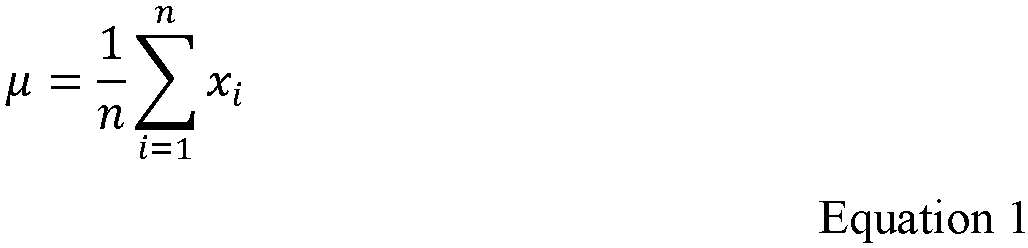
Equation 1, which requires a processing unit to have access to a large memory if the quantity i of the samples xi is large. In addition, the computation may experience an overflow condition during summation if the quantity i of the samples xi sums to a value that is too great for the processing unit to handle. - The
radar system 102 performsoperations 702 through 716 to perform an incremental mean and standard deviation calculation based on an incremental mean µn computation expressed asEquation 2. TheEquation 2 is based on theEquation 1, but rewritten as follows:
fraction 1/n of the difference between the current sample xn and the current mean µn-1.Equation 2 provides a more stable computation thanEquation 1 becauseEquation 2 avoids the accumulation of large sums. - Below is
Equation 3, which is the equation a conventional radar system uses to calculate the standard deviation σ: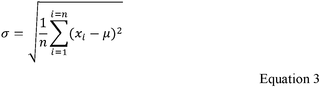
Equation 3. During the first pass, the conventional radar system calculates the mean µ for all the samples xi. Then, during a second pass, the radar system sums the square of the distances from each of the samples xi to the mean µ. - After some rearrangement, the calculation of the standard deviation σ in the
Equation 3 can be rewritten asEquation 4, which follows as:
Equation 4 requires all the samples xi to be already collected and stored. Secondly, theEquation 4 is dependent on the arithmetic mean µ calculation (Equation 1), which has overflow precision issues with large sample sizes (e.g., in implementations where i is a large integer). These two issues are resolved through use of an incrementally updated variance formula Sn , as explained below. - As shown below in
Equation 5, theradar system 102 incrementally updates the variance Sn by assuming:
- When combined with the
Equation 2, the variance Sn from theEquation 5 can be re-written as shown below in Equation 6:
- After further derivation, the
Equations 
- The variance Sn from the Equation 7 leads to the incremental standard deviation σ, as shown in the Equation 8:

radar system 102 to maintain a cumulative sum for all the frames, nor does theradar system 102 suffer from the potential overflow issues that a conventional radar system can experience by computing the standard deviation σ strictly following theEquation 3. - The
radar system 102 need not store any of the samples x for the final calculation. Instead, theradar system 102 can simply store a previous variance S n-1 value and continuously update the previously stored variance value S n-1 to compute the standard deviation σ according to the Equation 8, as theradar system 102 receives new samples xn . Given the above derivation, theradar system 102 executes theoperations 702 through 714 to update the standard deviation incrementally with each new sample xn based on the principles of the Equation 8. - At 702, the
processing unit 212 of theradar system 102 directs atransceiver 210 to detect living objects by generating a first plurality offrames 1 through (n - 1), using a chirp pattern that has a first period of multiple chirps followed by a second period of idle time. At 704, theprocessing unit 212 applies a Fourier transform, such as a FFT, to radar reflections obtained during the first period within each of the first plurality of frames to determine a respective amplitude, as a function of range, for each of the first plurality of frames. - At 706, the
processing unit 212 determines a first standard deviation σ n-1 in amplitude as a function of range based on the respective amplitude determined for each of the first plurality of frames. In computing the first standard deviation, the processing unit computes a mean amplitude. Theprocessing unit 212 sets and stores, at 708, a previous mean amplitude µ n-1 to a value equal to a mean amplitude µ n-1 for the first plurality of frames. - Then, at 710, the
processing unit 212 directs thetransceiver 210 to detect living objects by generating a subsequent frame n using the same chirp pattern used at 702. Theprocessing unit 212 applies a Fourier transform to radar reflections obtained during the subsequent frame to determine an amplitude as a function of range of the receiver signal for the subsequent frame. - The
processing unit 212 determines a current mean µn equal to the previous mean µ n-1 incremented by a fraction of the amplitude xn for the subsequent frame n, per theEquation 2. The fraction of the amplitude xn of the subsequent frame n is equal to a difference between the amplitude xn of the subsequent frame n and the previous mean µ n-1, the difference being divided by a total quantity of frames n among the plurality offrames 1 through n. - A standard deviation σn of the plurality of frames and the subsequent frame is determined by incrementing the standard deviation σ n-1 by a function of the range xn of the subsequent frame n, the previous mean µ n-1, and the current mean µn . For example, the function of the range xn of the subsequent frame n, the previous mean µ n-1, and the current mean µn is based on a product of the amplitude of the subsequent frame minus the previous mean and the amplitude of the subsequent frame minus the current mean (see the Equation 7 which controls the results of the Equation 8).
- At 712, the radar system determines whether the standard deviation in the amplitude σn satisfies a noise threshold. Responsive to the standard deviation σn-1 satisfying a noise threshold at 712, the
processing unit 212 outputs, at 714, an indication of aliving object 108 detected during the plurality offrames 1 through n. Otherwise, in response to the standard deviation σ n-1 not satisfying the noise threshold at 712, theprocessing unit 212 returns to theoperation 710 for generating additional frames to detect aliving object 108. - Each time the
radar system 102 computes a current mean µn theradar system 102 later stores the current mean µn as the previous mean µn to be used during calculation of a subsequent mean µ n+1. For example, the living-object detector 222 uses the previous mean µ n-1 to determine a current mean µn and stores the current mean µn as the previous mean µ n-1 in a memory of the computer-readable storage media 214 or storage media otherwise accessible to theprocessing unit 212. - The
operations living object 108 is detected, or based on some other criteria (e.g., quantity of frames, duration of time). For example, after generating another plurality of frames (n + 1), theprocessing unit 212 determines the current mean µ n+1. The current mean µ n+1 is equal to the previous mean µn incremented by a fraction of an amplitude x n+1 of a current plurality of frames as a function of range. The fraction of the amplitude x n+1 is equal to a difference between the amplitude x n+1 of the new frame and the previous mean µn , the difference being divided by a total quantity (n + 1) of frames. - A standard deviation σn+1 of the plurality of frames (n + 1) is determined by incrementing the standard deviation σn by a function of the amplitude x n+1 of the plurality of frames n+1, the previous mean µn , and the current mean µ n+1. At 712, the radar system determines whether the standard deviation σn+1 satisfies the noise threshold, which may be an adaptive threshold. Responsive to the standard deviation σ n+1 satisfying the noise threshold at 712, the
processing unit 212 outputs, at 714, an indication of theliving object 108 detected during the plurality offrames 1 through n + 1. - Otherwise, in response to the standard deviation σn+1 not satisfying the noise threshold at 712, the
processing unit 212 stores the current mean µ n+1 as the previous mean µ n+1 and returns to theoperation 710 for generating additional frames to detect aliving object 108. In response to the standard deviation σn+1 not satisfying the noise threshold at 712, theprocessing unit 212 refrains from outputting an indication of a living object. -
FIGS. 7-2 through 7-4 illustrate an example of power drift in an FMCW radar system. For responsive and quick detection of living targets, theradar system 102 processes radar data as soon as theradar system 102 powers on. However, it is common that the components of the radar system 102 (e.g., which may be made of Silicon) need a period of time after theradar system 102 powers on, before the components are stable. An example of power drift is shown in the sequence ofFIGS. 7-2 through 7-4 . Theradar system 102 takes more than four minutes, for example, to report a correct and stable amplitude x of radar reflections as a function of range. Power drifting may introduce a false trigger to a detection of a living target by introducing errors in the calculation of the standard deviation σ. - The
radar system 102 may prevent false triggers to detections by correcting for a slope k of the power drifting. Where xn is the last sample and x 1 is the first sample, theradar system 102 obtains the slope k of the samples by calculating Equation 9 as follows:
radar system 102 compensates for false triggers to detections, based on the slope k of the samples x. To improve performance, theradar system 102 may incrementally compensate for the false triggers to detections resulting from the power drift. -
FIG. 7-5 illustrates an example adaptive threshold during part of a frame generated by an FMCW radar system that corrects for power drift.FIG. 7-5 shows the effects of drift correction on an original signal; the false peak is substantially reduced after using drift correction. The original signal can represent a return from a living object. Similarly, an adaptive threshold that follows the noise response of theradar system 102 can benefit from drift correction to make theliving object 108 readily detectable. - To put the slope correction into the incremental mean and standard deviation calculations of the Equations 7 and 8, a new mean mn is defined in
Equations 10 through 13:


- Because both µn and In can be calculated incrementally, mn can also been calculated incrementally. Adding slope correction into the
Equations 
- The Equation 14 can be reduced to
Equations 15 through 19. Based on theEquations 15 through 19, the Equation 14 for the new variance v can be rewritten intoEquation 20, which enables incremental computation of the standard deviation σ including compensating for power drift.


Equation 20 and the new variance v 2 can also be calculated incrementally. Computing the standard deviation from computing variance in this way significantly reduces memory requirements. With incremental calculation and slope correction, theradar system 102 detects living targets without potential for overflow or false triggers to detections. - The following are additional examples of radar-based detection of living objects.
- Example 1. A radar system comprising: an antenna array; a transceiver configured to generate radar signals via the antenna array; and a processing unit configured to: direct the transceiver to generate, for a plurality of frames, the radar signals having a chirp pattern that has a first period of multiple chirps followed by a second period of idle time; apply a Fourier transform to respective reflections of the radar signals obtained during each of the plurality of frames to determine a respective amplitude of the reflections as a function of range for each of the plurality of frames; based on the respective amplitude of the reflections for each of the plurality of frames, determine a standard deviation in the respective amplitude for the reflections within each of the plurality of frames; and in response to the standard deviation in the respective amplitude for any of the reflections within the plurality of frames satisfying a noise threshold, output, an indication of a living object detected during the plurality of frames.
- Example 2. The radar system of any of the preceding examples, wherein the processing unit is configured to determine the respective amplitude of the reflections as a function of range for each of the plurality of frames by applying the Fourier transform to a respective receiver signal of each of the multiple chirps in each frame, the respective receiver signal of each of the multiple chirps in each frame including a respective digital beat signal including respective baseband data.
- Example 3. The radar system of any of the preceding examples, wherein the processing unit is further configured to determine the respective amplitude of the reflections as a function of range for each of the plurality of frames by integrating, using non-coherent integration, results of the applying the Fourier transform to the respective receiver signal of each chirp of the multiple chirps in each frame over the plurality of frames.
- Example 4. The radar system of any of the preceding examples, wherein the processing unit is configured to apply the Fourier transform to the multiple chirps by applying the Fourier transform to a common receiver signal for the multiple chirps in each frame over the plurality of frames.
- Example 5. The radar system of any of the preceding examples, wherein the processing unit is configured to determine the common receiver signal for the multiple chirps in each frame by averaging respective receiver signals of each of the multiple chirps in that frame.
- Example 6. The radar system of any of the preceding examples, wherein the processing unit is configured to determine the common receiver signal for the multiple chirps in each frame by summing respective receiver signals of each of the multiple chirps in that frame.
- Example 7. The radar system of any of the preceding examples, wherein: the radar system is integrated in a vehicle; a field-of-view of the radar system includes one or more areas occupied by passengers of the vehicle; the indication of the living object detected during the plurality of frames is an indication of a passenger of the vehicle; and the processing unit is further configured to output the indication of the passenger of the vehicle to an alert system that is configured to output an alert about the passenger of the vehicle.
- Example 8. The radar system of any of the preceding examples, wherein the second period of idle time is longer than the first period of multiple chirps.
- Example 9. The radar system of any of the preceding examples, wherein the first period is approximately two or more microseconds and the second period is less than approximately 100 milliseconds.
- Example 10. The radar system of any of the preceding examples, wherein the noise threshold is a predetermined threshold based on predetermined characteristics of the radar system.
- Example 11. The radar system of any of the preceding examples, wherein the noise threshold is an adaptive noise threshold as a function of range and the processing unit is further configured to adjust the adaptive noise threshold based on a dynamic noise response of the radar system.
- Example 12. The radar system of any of the preceding examples, wherein the standard deviation is a current standard deviation, the processing unit is further configured to: determine a baseline standard deviation in amplitude for reflections obtained in at least two prior frames based on a respective amplitude as a function of range for each of the at least two prior frames; and determine the adaptive noise threshold by smoothing the baseline standard deviation and setting the adaptive noise threshold to the baseline standard deviation.
- Example 13. The radar system of any of the preceding examples, wherein the processing unit is further configured to optionally add an offset to the baseline standard deviation after smoothing the baseline standard deviation to determine the adaptive noise threshold.
- Example 14. The radar system of any of the preceding examples, wherein the standard deviation is a first standard deviation, wherein the processing unit is further configured to: direct the transceiver to generate, for a subsequent frame, the chirp pattern that has the first period of multiple chirps followed by the second period of idle time; determine, based in part on the first standard deviation and a respective amplitude as a function of range for the subsequent frame, a second standard deviation in the respective amplitude for the reflections within the subsequent frame and each of the plurality of frames; and in response to the second standard deviation not satisfying the noise threshold, refrain from outputting the indication of the object.
- Example 15. The radar system of any of the preceding examples, wherein the standard deviation is a first standard deviation, wherein the processing unit is further configured to: direct the transceiver to generate, for a subsequent frame, the chirp pattern that has the first period of multiple chirps followed by the second period of idle time; determine, based in part on the first standard deviation and an amplitude as a function of range for the subsequent frame, a second standard deviation as a function of range in the amplitude for the reflections within the subsequent frame and each of the plurality of frames; and in response to the second standard deviation satisfying the noise threshold, output the indication of the object.
- Example 16. The radar system of any of the preceding examples, wherein the processing unit is further configured to: determine a previous mean amplitude equal to a mean amplitude for the plurality of frames; determine a current mean amplitude equal to the previous mean amplitude incremented by a fraction of the amplitude of the subsequent frame, the fraction of the amplitude of the subsequent frame being equal to a difference between the range of the subsequent frame and the previous mean, the difference being divided by a total quantity of frames among the plurality of frames and the subsequent frame; and determine the second standard deviation by incrementing the first standard deviation according to a function of the amplitude of the subsequent frame, the previous mean amplitude, and the current mean amplitude.
- Example 17. The radar system of any of the preceding examples, wherein the function of the amplitude of the subsequent frame, the previous mean amplitude, and the current mean amplitude computes a product of a first difference between the amplitude of the subsequent frame and the previous mean amplitude and a second difference between the amplitude of the subsequent frame and the current mean amplitude.
- Example 18. The radar system of any of the preceding examples, wherein the processing unit is further configured to store the current mean amplitude as the previous mean amplitude for use in subsequently determining a new, current mean in response to a new frame.
- Example 19. A computer-readable storage medium comprising instructions that, when executed by a processing unit of a radar system, cause the processing unit to: direct a transceiver of the radar system to generate a plurality of frames of radar signals having a chirp pattern that has a first period of multiple chirps followed by a second period of idle time; apply a Fourier transform to respective reflections obtained during the first period of each of the plurality of frames to determine a respective amplitude of the reflections as a function of range for each of the plurality of frames; based on the respective amplitude of the reflections for each of the plurality of frames, determine a standard deviation in the respective amplitude for the reflections within each of the plurality of frames; and in response to the standard deviation in the respective amplitude for any of the reflections within the plurality of frames satisfying a noise threshold, output, an indication of a living object detected during the plurality of frames.
- Example 20. A method comprising: generating, by a radar system, a plurality of frames of radar signals having a chirp pattern that has a first period of multiple chirps followed by a second period of idle time; applying, by the radar system, a Fourier transform to respective reflections obtained during the generating of the first period of each of the plurality of frames to determine a respective amplitude of the reflections as a function of range for each of the plurality of frames; based on the respective amplitude of the reflections for each of the plurality of frames, determining, by the radar system, a standard deviation in the respective amplitude for the reflections within each of the plurality of frames; and in response to the standard deviation in the respective amplitude for any of the reflections within the plurality of frames satisfying a noise threshold, output, an indication of a living object detected during the plurality of frames.
- Example 21. A radar system comprising: an antenna array; a transceiver configured to generate radar signals via the antenna array; and a processing unit configured to: direct the transceiver to generate, over a first plurality of frames, the radar signals having a chirp pattern that has a first period of multiple chirps followed by a second period of idle time; determine a respective amplitude as a function of range for the reflections obtained during each of the first plurality of frames; based on the respective amplitude for the reflections obtained during each of the plurality of frames, determine a baseline standard deviation in amplitude as a function of range for the first plurality of frames; adjust an adaptive noise threshold based on a dynamic noise response of the radar system by smoothing the baseline standard deviation for the first plurality of frames and setting the adaptive noise threshold to the baseline standard deviation after the smoothing; and responsive to a standard deviation in amplitude as a function of range for a second plurality of frames generated using the chirp pattern satisfying the adaptive noise threshold, output an indication of a living object detected during the second plurality of frames.
- Example 22. The radar system of any of the preceding examples, wherein the processing unit is further configured to optionally add an offset to the baseline standard deviation after smoothing the baseline standard deviation.
- Example 23. The radar system of any of the preceding examples, wherein the processing unit is further configured to: smooth the standard deviation for the second plurality of frames; set the adaptive noise threshold for a third plurality of frames generated using the chirp pattern to the smoothed standard deviation for the second plurality of frames; and responsive to a standard deviation in amplitude as a function of range for the third plurality of frames satisfying the adaptive noise threshold set for the third plurality of frames, output an indication of a living object detected during the third plurality of frames.
- Example 24. The radar system of any of the preceding examples, wherein the processing unit is further configured to add the offset to the smoothed standard deviation for the second plurality of frames before setting the adaptive noise threshold to the smoothed standard deviation for the second plurality of frames.
- Example 25. The radar system of any of the preceding examples, wherein the processing unit is configured to determine the respective amplitude for each of the first plurality of frames by applying a Fourier transform to respective receiver signals of the multiple chirps in each of the first plurality of frames.
- Example 26. The radar system of any of the preceding examples, wherein the processing unit is configured to determine the respective amplitude for each of the first plurality of frames by integrating, using non-coherent integration, results of the applying the Fourier transform to the respective receiver signals of each of the multiple chirps in each of the first plurality of frames.
- Example 27. The radar system of any of the preceding examples, wherein the processing unit is configured to determine the respective amplitude for each of the first plurality of frames by applying a Fourier transform to a common receiver signal for the multiple chirps in each of the first plurality of frames.
- Example 28. The radar system of any of the preceding examples, wherein the processing unit is configured to determine the common receiver signal for the multiple chirps in each of the first plurality of frames by averaging respective receiver signals of each of the multiple chirps in that frame.
- Example 29. The radar system of any of the preceding examples, wherein the processing unit is configured to determine the common receiver signal for the multiple chirps in each of the first plurality of frames by summing respective receiver signals of each of the multiple chirps in that frame.
- Example 30. The radar system of any of the preceding examples, wherein the second period of idle time is longer than the first period of multiple chirps.
- Example 31. The radar system of any of the preceding examples, wherein the second period of idle time is an order of five magnitudes longer than the first period of multiple chirps.
- Example 32. The radar system of any of the preceding examples, wherein the first period is approximately two or more microseconds and the second period is less than approximately 100 milliseconds.
- Example 33. The radar system of any of the preceding examples, wherein the processing unit is further configured to: direct the transceiver to generate the chirp pattern in a third frame after the second plurality of frames; determine, based on the standard deviation in amplitude for the second plurality of frames and an amplitude as a function of range for the third frame, a standard deviation in amplitude as a function of range for the third frame; and based on whether the standard deviation in amplitude for the third frame satisfies the adaptive noise threshold, output or refrain from outputting an indication of a living object detected during the third frame.
- Example 34. The radar system of any of the preceding examples, wherein the processing unit is further configured to: smooth the standard deviation in amplitude for the second plurality of frames; and set the adaptive noise threshold for the third frame to the smoothed, standard deviation in amplitude for the second plurality of frames.
- Example 35. The radar system of any of the preceding examples, wherein the processing unit is further configured to optionally add an offset to the smoothed, standard deviation in amplitude for the second plurality of frames before setting the adaptive noise threshold for the third frame to the smoothed, standard deviation for the second plurality of frames.
- Example 36. The radar system of any of the preceding examples, wherein the processing unit is further configured to: output the indication of the living object detected during the third frame in response to the standard deviation for the third frame satisfying the adaptive noise threshold.
- Example 37. The radar system of any of the preceding examples, wherein the processing unit is further configured to: determine a previous mean amplitude equal to a mean amplitude for the second plurality of frames; determine a current mean amplitude equal to the previous mean amplitude incremented by a fraction of the amplitude of the third frame, the fraction of the amplitude of the third frame being equal to a difference between the amplitude of the third frame and the previous mean amplitude, the difference being divided by a total quantity of frames among the second plurality of frames and the third frame; determine the standard deviation in amplitude for the third frame by incrementing the baseline standard deviation by an amount determined based on the amplitude of the third frame, the previous mean amplitude, and the current mean amplitude; and store the current mean amplitude as the previous mean amplitude for use in subsequently incrementing the current mean amplitude.
- Example 38. The radar system of any of the preceding examples, wherein the amount determined based on the range of the third frame, the previous mean, and the current mean is based on a product of the amplitude of the third frame minus the previous mean amplitude and the amplitude of the third frame minus the current mean amplitude.
- Example 39. A computer-readable storage medium comprising instructions that, when executed by a processing unit of a radar system, cause the processing unit to: direct a transceiver to generate, over a first plurality of frames, radar signals having a chirp pattern that has a first period of multiple chirps followed by a second period of idle time; determine a respective amplitude as a function of range for reflections of the radar signals obtained during each of the first plurality of frames; based on the respective amplitude for the reflections obtained during each of the plurality of frames, determine a baseline standard deviation in amplitude as a function of range for the first plurality of frames; adjust an adaptive noise threshold based on a dynamic noise response of the radar system by smoothing the baseline standard deviation for the first plurality of frames and setting the adaptive noise threshold to the baseline standard deviation after the smoothing; and responsive to a standard deviation in amplitude as a function of range for a second plurality of frames generated using the chirp pattern satisfying the adaptive noise threshold, output an indication of a living object detected during the second plurality of frames.
- Example 40. A method comprising: generating, by a radar system, over a first plurality of frames, radar signals having a chirp pattern that has a first period of multiple chirps followed by a second period of idle time; determining, by the radar system, a respective amplitude as a function of range for reflections of the radar signals obtained during each of the first plurality of frames; based on the respective amplitude for the reflections obtained during each of the plurality of frames, determining, by the radar system, a baseline standard deviation in amplitude as a function of range for the first plurality of frames; adjusting, by the radar system, an adaptive noise threshold based on a dynamic noise response of the radar system by smoothing the baseline standard deviation for the first plurality of frames and setting the adaptive noise threshold to the baseline standard deviation after the smoothing; and responsive to a standard deviation in amplitude as a function of range for a second plurality of frames generated using the chirp pattern satisfying the adaptive noise threshold, outputting, by the radar system, an indication of a living object detected during the second plurality of frames.
- Example 41. A radar system comprising: an antenna array; a transceiver configured to generate radar signals via the antenna array; and a processing unit configured to: direct the transceiver to generate a first plurality of frames of radar signals having a chirp pattern that has a first period of multiple chirps followed by a second period of idle time; apply a Fourier transform to reflections of the radar signals obtained within the first plurality of frames to determine a respective amplitude, as a function of range, for each of the first plurality of frames; determine a first standard deviation in amplitude for the first plurality of frames based on the respective amplitude determined for each of the first plurality of frames; store a previous mean amplitude equal to a mean amplitude for the first plurality of frames; direct the transceiver to generate the chirp pattern in a subsequent frame to the first plurality of frames; determine a current mean amplitude equal to the previous mean amplitude incremented by a fraction of an amplitude, as a function of range, of the subsequent frame, the fraction of the range of the subsequent frame being equal to a difference between the amplitude of the subsequent frame and the previous mean amplitude, the difference being divided by a total quantity of frames among the first plurality of frames and the subsequent frame; determine a second standard deviation in amplitude of the first plurality of frames and the subsequent frame by incrementing the first standard deviation in amplitude by an amount based on the amplitude of the subsequent frame, the previous mean amplitude, and the current mean amplitude; and responsive to the second standard deviation satisfying a noise threshold, output an indication of a living object detected during the first plurality of frames and the subsequent frame.
- Example 42. The radar system of any of the preceding examples, wherein the processing unit is further configured to: store the current mean amplitude as the previous mean amplitude for subsequently incrementing the current mean for another subsequent frame.
- Example 43. The radar system of any of the preceding examples, wherein the processing unit is further configured to: direct the transceiver to generate the chirp pattern in the other subsequent frame; determine the current mean amplitude being equal to the previous mean amplitude incremented by a fraction of an amplitude, as a function of range, of the other subsequent frame, the fraction of the amplitude of the other subsequent frame being equal to a difference between the amplitude of the other subsequent frame and the previous mean amplitude, the difference being divided by a total quantity of frames among the first plurality of frames, the subsequent frame, and the other subsequent frame; and determine a third standard deviation in amplitude for the first plurality of frames, the subsequent frame, and the other subsequent frame by incrementing the second standard deviation by a function of the range of the subsequent frame, the previous mean, and the current mean; and responsive to the third standard deviation satisfying the noise threshold, output an indication of a living object detected during the first plurality of frames, the subsequent frame, and the other subsequent frame.
- Example 44. The radar system of any of the preceding examples, wherein the function of the range of the subsequent frame, the previous mean amplitude, and the current mean amplitude is based on a product of the amplitude of the subsequent frame minus the previous mean amplitude and the amplitude of the subsequent frame minus the current mean amplitude.
- Example 45. The radar system of any of the preceding examples, wherein the processing unit is configured to apply the Fourier transform to the first plurality of frames by applying the Fourier transform to respective receiver signals of each of the multiple chirps in each frame.
- Example 46. The radar system of any of the preceding examples, wherein the processing unit is further configured to apply the Fourier transform to the first plurality of frames by integrating, using non-coherent integration, results of the applying the Fourier transform to the respective receiver signal of each chirp from the multiple chirps in each frame.
- Example 47. The radar system of any of the preceding examples, wherein the processing unit is configured to apply the Fourier transform to the first plurality of frames by applying the Fourier transform to a common receiver signal of the multiple chirps in each frame.
- Example 48. The radar system of any of the preceding examples, wherein the processing unit is configured to determine the common receiver signal of the multiple chirps in each frame by averaging the respective receiver signals of the multiple chirps in that frame.
- Example 49. The radar system of any of the preceding examples, wherein the processing unit is configured to determine the common receiver signal of the multiple chirps in each frame by summing the respective receiver signals of the multiple chirps in that frame.
- Example 50. The radar system of any of the preceding examples, wherein the second period of idle time is longer than the first period of multiple chirps.
- Example 51. The radar system of any of the preceding examples, wherein the processing unit is further configured to determine the first standard deviation for the first plurality of frames or the mean amplitude for the first plurality of frames by compensating for false triggers to detections resulting from power drift of the radar system.
- Example 52. The radar system of any of the preceding examples, wherein the processing unit is further configured to incrementally compensate for the false triggers to detections resulting from the power drift.
- Example 53. The radar system of any of the preceding examples, wherein the noise threshold is a predetermined threshold based on radar characteristics of the radar system.
- Example 54. The radar system of any of the preceding examples, wherein the noise threshold is an adaptive noise threshold and the processing unit is further configured to adjust the adaptive noise threshold based on a dynamic noise response of the radar system.
- Example 55. The radar system of any of the preceding examples, wherein the first standard deviation is a baseline standard deviation and the processing unit is further configured to: determine the adaptive noise threshold by smoothing the baseline standard deviation and setting the adaptive noise threshold to the baseline standard deviation.
- Example 56. The radar system of any of the preceding examples, wherein the processing unit is further configured to optionally add an offset to the baseline standard deviation after smoothing the baseline standard deviation to determine the adaptive noise threshold.
- Example 57. The radar system of any of the preceding examples, wherein the processing unit is further configured to: direct the transceiver to generate the chirp pattern in another subsequent frame following the subsequent frame; determine, based in part on the second standard deviation and a respective amplitude for the other subsequent frame, a third standard deviation; and in response to the third standard deviation not satisfying the noise threshold, refrain from outputting an indication of an object detected in the other subsequent frame.
- Example 58. The radar system of any of the preceding examples, wherein the transceiver includes a transmitter and the receiver.
- Example 59. A computer-readable storage medium comprising instructions that, when executed by a processing unit of a radar system, cause the processing unit to: direct a transmitter and a receiver of the radar system to generate a first plurality of frames of radar signals having a chirp pattern that has a first period of multiple chirps followed by a second period of idle time; apply a Fourier transform to reflections of the radar signals obtained within the first plurality of frames to determine a respective amplitude, as a function of range, for each of the first plurality of frames; determine a first standard deviation in amplitude for the first plurality of frames based on the respective amplitude determined for each of the first plurality of frames; store a previous mean amplitude equal to a mean amplitude for the first plurality of frames; direct the transceiver to generate the chirp pattern in a subsequent frame to the first plurality of frames; determine a current mean amplitude equal to the previous mean amplitude incremented by a fraction of an amplitude, as a function of range, of the subsequent frame, the fraction of the range of the subsequent frame being equal to a difference between the amplitude of the subsequent frame and the previous mean amplitude, the difference being divided by a total quantity of frames among the first plurality of frames and the subsequent frame; determine a second standard deviation in amplitude of the first plurality of frames and the subsequent frame by incrementing the first standard deviation in amplitude by an amount based on the amplitude of the subsequent frame, the previous mean amplitude, and the current mean amplitude; and responsive to the second standard deviation satisfying a noise threshold, output an indication of a living object detected during the first plurality of frames and the subsequent frame.
- Example 60. A method comprising: generating, by a radar system, a first plurality of frames of radar signals having a chirp pattern that has a first period of multiple chirps followed by a second period of idle time; applying a Fourier transform to reflections of the radar signals obtained within the first plurality of frames to determine a respective amplitude, as a function of range, for each of the first plurality of frames; determining a first standard deviation in amplitude for the first plurality of frames based on the respective amplitude determined for each of the first plurality of frames; storing, by the radar system, a previous mean amplitude equal to a mean amplitude for the first plurality of frames; generating, by the radar system, the chirp pattern in a subsequent frame to the first plurality of frames; determining a current mean amplitude equal to the previous mean amplitude incremented by a fraction of an amplitude, as a function of range, of the subsequent frame, the fraction of the range of the subsequent frame being equal to a difference between the amplitude of the subsequent frame and the previous mean amplitude, the difference being divided by a total quantity of frames among the first plurality of frames and the subsequent frame; determining a second standard deviation in amplitude of the first plurality of frames and the subsequent frame by incrementing the first standard deviation in amplitude by an amount based on the amplitude of the subsequent frame, the previous mean amplitude, and the current mean amplitude; and responsive to the second standard deviation satisfying a noise threshold, outputting, by the radar system, to a system of a vehicle, an indication of a living object detected in the vehicle during the first plurality of frames and the subsequent frame.
- While various embodiments of the disclosure are described in the foregoing description and shown in the drawings, it is to be understood that this disclosure is not limited thereto but may be variously embodied to practice within the scope of the following claims. From the foregoing description, it will be apparent that various changes may be made without departing from the spirit and scope of the disclosure as defined by the following claims.
Claims (19)
- A system comprising a processing unit configured to direct a radar system to:generate, for each frame of a plurality of frames, radar signals having a repeating chirp pattern that has a first period of multiple chirps followed by a second period of idle time for each frame of the plurality of frames, the second period of idle time being longer than the first period of multiple chirps;determine a respective amplitude as a function of range for each of the plurality of frames;determine a standard deviation in the respective amplitude as a function of range, between at least two of the plurality of frames;determine whether the standard deviation satisfies a noise threshold; andin response to determining that the standard deviation satisfies the noise threshold, output an indication of a living object detected during the plurality of frames.
- The system of claim 1, wherein:the radar system is integrated in a vehicle;a field-of-view of the radar system includes one or more areas occupied by passengers of the vehicle;the indication of the living object detected during the plurality of frames is an indication of a passenger of the vehicle; andthe processing unit is further configured to output the indication of the passenger of the vehicle to an alert system that is configured to output an alert about the passenger of the vehicle.
- The system of claim 2, wherein:
the radar system comprises the processing unit. - The system of claim 1, wherein the processing unit is configured to determine the respective amplitude of the reflections of the radar signals as a function of range for a plurality of frames by applying a Fourier transform to a respective receiver signal of each of the multiple chirps in each frame, the respective receiver signal of each of the multiple chirps in each frame including a respective digital beat signal including respective baseband data.
- The system of claim 1, wherein the multiple chirps have individual frequencies that increase or decrease over time.
- The system of claim 1, wherein the multiple chirps have a frequency modulation with a two-slope cycle, the two-slope cycle including individual frequencies that increase and decrease over time.
- The system of claim 1, wherein the multiple chirps have a frequency modulation with a single-slope cycle that decrease linearly over time.
- The system of claim 1, wherein the first period is approximately two or more microseconds and the second period is less than approximately 100 milliseconds.
- A non-transitory computer-readable storage medium comprising instructions that, when executed, cause a processing unit to direct a radar system to:generate, for each frame of a plurality of frames, radar signals having a repeating chirp pattern that has a first period of multiple chirps followed by a second period of idle time for each frame of the plurality of frames, the second period of idle time being longer than the first period of multiple chirps;determine a respective amplitude as a function of range for each of the plurality of frames;determine a standard deviation in the respective amplitude as a function of range, between at least two of the plurality of frames;determine whether the standard deviation satisfies a noise threshold; andin response to determining that the standard deviation satisfies the noise threshold, output an indication of a living object detected during the plurality of frames.
- The non-transitory computer-readable storage medium of claim 9, wherein the non-transitory computer-readable storage medium comprises further instructions that, when executed, cause the processing unit to determine the respective amplitude of the reflections of the radar signals as a function of range for a plurality of frames by applying a Fourier transform to a respective receiver signal of each of the multiple chirps in each frame, the respective receiver signal of each of the multiple chirps in each frame including a respective digital beat signal including respective baseband data.
- The non-transitory computer-readable storage medium of claim 9, wherein the multiple chirps have individual frequencies that increase or decrease over time.
- The non-transitory computer-readable storage medium of claim 9, wherein the multiple chirps have a frequency modulation with a two-slope cycle, the two-slope cycle including individual frequencies that increase and decrease over time.
- The non-transitory computer-readable storage medium of claim 9, wherein the multiple chirps have a frequency modulation with a single-slope cycle that decrease linearly over time.
- The non-transitory computer-readable storage medium of claim 9, wherein the first period is approximately two or more microseconds and the second period is less than approximately 100 milliseconds.
- The non-transitory computer-readable storage medium of claim 9, wherein:the noise threshold is an adaptive noise threshold as a function of range; andthe non-transitory computer-readable storage medium comprises further instructions that, when executed, cause the processing unit to adjust the adaptive noise threshold based on a dynamic noise response of the radar system.
- The non-transitory computer-readable storage medium of claim 9, wherein:the noise threshold is an adaptive noise threshold; andthe non-transitory computer-readable storage medium comprises further instructions that, when executed, cause the processing unit to:determine a baseline standard deviation in amplitude for reflections obtained in at least two prior frames based on a respective amplitude as a function of range for each of the at least two prior frames; anddetermine the adaptive noise threshold by smoothing the baseline standard deviation and setting the adaptive noise threshold to the smoothed baseline standard deviation.
- The non-transitory computer-readable storage medium of claim 16, wherein the non-transitory computer-readable storage medium comprises further instructions that, when executed, cause the processing unit to add an offset to the smoothed baseline standard deviation after smoothing the baseline standard deviation to determine the adaptive noise threshold.
- The non-transitory computer-readable storage medium of claim 9, wherein:the radar system is integrated in a vehicle;the processing unit is integrated in the vehicle as part of the radar system;a field-of-view of the radar system includes one or more areas occupied by passengers of the vehicle;the indication of the living object detected during the plurality of frames is an indication of a passenger of the vehicle; andthe non-transitory computer-readable storage medium comprises further instructions that, when executed, cause the processing unit to output the indication of the passenger of the vehicle to an alert system that is configured to output an alert about the passenger of the vehicle.
- A method comprising:generating, by a processing unit, for each frame of a plurality of frames, radar signals having a repeating chirp pattern that has a first period of multiple chirps followed by a second period of idle time for each frame of the plurality of frames, the second period of idle time being longer than the first period of multiple chirps;determining, by the processing unit, a respective amplitude as a function of range for each of the plurality of frames;determining, by the processing unit, a standard deviation in the respective as a function of range, between at least two of the plurality of frames;determining, by the processing unit, whether the standard deviation satisfies a noise threshold; andin response to determining that the standard deviation satisfies the noise threshold, outputting, by the processing unit, an indication of a living object detected during the plurality of frames.
Applications Claiming Priority (2)
| Application Number | Priority Date | Filing Date | Title |
|---|---|---|---|
| US16/825,170 US11385344B2 (en) | 2020-03-20 | 2020-03-20 | Frequency-modulated continuous-wave (FMCW) radar-based detection of living objects |
| EP21151688.5A EP3882652B1 (en) | 2020-03-20 | 2021-01-14 | Frequency-modulated continuous-wave (fmcw) radar-based detection of living objects |
Related Parent Applications (2)
| Application Number | Title | Priority Date | Filing Date |
|---|---|---|---|
| EP21151688.5A Division-Into EP3882652B1 (en) | 2020-03-20 | 2021-01-14 | Frequency-modulated continuous-wave (fmcw) radar-based detection of living objects |
| EP21151688.5A Division EP3882652B1 (en) | 2020-03-20 | 2021-01-14 | Frequency-modulated continuous-wave (fmcw) radar-based detection of living objects |
Publications (2)
| Publication Number | Publication Date |
|---|---|
| EP4530671A2 true EP4530671A2 (en) | 2025-04-02 |
| EP4530671A3 EP4530671A3 (en) | 2025-06-11 |
Family
ID=74184526
Family Applications (2)
| Application Number | Title | Priority Date | Filing Date |
|---|---|---|---|
| EP21151688.5A Active EP3882652B1 (en) | 2020-03-20 | 2021-01-14 | Frequency-modulated continuous-wave (fmcw) radar-based detection of living objects |
| EP25157065.1A Pending EP4530671A3 (en) | 2020-03-20 | 2021-01-14 | Frequency-modulated continuous-wave (fmcw) radar-based detection of living objects |
Family Applications Before (1)
| Application Number | Title | Priority Date | Filing Date |
|---|---|---|---|
| EP21151688.5A Active EP3882652B1 (en) | 2020-03-20 | 2021-01-14 | Frequency-modulated continuous-wave (fmcw) radar-based detection of living objects |
Country Status (3)
| Country | Link |
|---|---|
| US (2) | US11385344B2 (en) |
| EP (2) | EP3882652B1 (en) |
| CN (2) | CN118294944A (en) |
Families Citing this family (21)
| Publication number | Priority date | Publication date | Assignee | Title |
|---|---|---|---|---|
| JP7241082B2 (en) * | 2018-08-10 | 2023-03-16 | 古野電気株式会社 | Ship operation support system, ship control device, ship control method, and program |
| US11709245B2 (en) * | 2019-04-29 | 2023-07-25 | Adnoviv Inc. | System and methods for radar-based detection of people in a room |
| US11396309B2 (en) * | 2020-04-03 | 2022-07-26 | Toyota Connected North America, Inc. | Management of vehicle sensors and responses to sensor data |
| KR102860885B1 (en) * | 2020-05-20 | 2025-09-18 | 삼성전자주식회사 | Method and apparatus for controling vehicle |
| US11381330B2 (en) | 2020-07-07 | 2022-07-05 | Aptiv Technologies Limited | Point-source model for simulating near-field effects from structures of an antenna |
| EP3943966A1 (en) * | 2020-07-22 | 2022-01-26 | Infineon Technologies AG | Radar devices and methods for radar devices |
| TWI762243B (en) * | 2021-03-17 | 2022-04-21 | 緯創資通股份有限公司 | Fmcw radar and method for processing digital signals and characterization information detection |
| US20240319332A1 (en) * | 2021-09-23 | 2024-09-26 | Intel Corporation | Apparatus, system, and method of scheduling radar transmissions |
| DE102022103818A1 (en) * | 2022-02-17 | 2023-08-17 | Gestigon Gmbh | METHOD AND SYSTEM FOR DETECTING A SEAT OCCUPANCY STATE OF A SEAT ARRANGEMENT BASED ON RADAR POINT CLOUDS |
| SE546203C2 (en) * | 2022-06-03 | 2024-07-02 | Husqvarna Ab | Method for controlling a robotic lawnmower in dependence of analysis of information acquired by means of a radar transceiver and a control unit therefor |
| CN115130501B (en) * | 2022-06-14 | 2025-08-15 | 森思泰克河北科技有限公司 | Target object detection method, device, computer equipment and storage medium |
| CN115140304B (en) * | 2022-06-20 | 2024-10-29 | 深圳市唐诚兴业科技有限公司 | Unmanned aerial vehicle intelligent detection prevention and control system |
| US12504510B2 (en) * | 2022-06-30 | 2025-12-23 | Gm Cruise Holdings Llc | Adaptive differential quantization for ranging sensors |
| US20240201779A1 (en) * | 2022-12-15 | 2024-06-20 | Amazon Technologies, Inc. | Presence detection with dynamic radar operating modes |
| US12115937B2 (en) * | 2022-12-20 | 2024-10-15 | T-Mobile Innovations Llc | On-board diagnostic second generation module incorporating a low power radar-based sensor |
| CN117031464B (en) * | 2023-07-25 | 2024-08-30 | 南京航空航天大学 | Method and device for distinguishing interference of moving living body and moving target in cabin |
| WO2025027770A1 (en) * | 2023-08-01 | 2025-02-06 | 三菱電機株式会社 | Occupant detection device and occupant detection method |
| US20250093497A1 (en) * | 2023-09-19 | 2025-03-20 | Aptiv Technologies AG | Range And Range Rate Estimation For Stepped Frequency Waveform With Constant Pulse Repetition Period |
| DE102023130585A1 (en) * | 2023-11-06 | 2025-05-08 | Valeo Schalter Und Sensoren Gmbh | METHOD FOR DETECTING INTERFERENCE IN A RADAR SYSTEM |
| US20250271567A1 (en) * | 2024-02-28 | 2025-08-28 | Clarion Corporation of America | Seat occupancy sensor system for vehicles and method of using the same |
| CN118980999B (en) * | 2024-08-28 | 2025-03-04 | 复睿智行智能科技(上海)有限公司 | Two-wheel vehicle seating detection method based on millimeter wave Lei Dadian cloud occupation grid analysis |
Family Cites Families (46)
| Publication number | Priority date | Publication date | Assignee | Title |
|---|---|---|---|---|
| US3114148A (en) * | 1958-09-09 | 1963-12-10 | Packard Bell Electronics Corp | Radar systems |
| US5508706A (en) * | 1991-09-30 | 1996-04-16 | Trw Inc. | Radar signal processor |
| US5886662A (en) * | 1997-06-18 | 1999-03-23 | Zai Amelex | Method and apparatus for remote measurement of terrestrial biomass |
| US6064334A (en) * | 1998-07-15 | 2000-05-16 | Trw Inc. | Clutter resistant target detector |
| US6762712B2 (en) * | 2001-07-26 | 2004-07-13 | Time Domain Corporation | First-arriving-pulse detection apparatus and associated methods |
| US6753780B2 (en) * | 2002-03-15 | 2004-06-22 | Delphi Technologies, Inc. | Vehicle occupant detection system and method using radar motion sensor |
| JP4016826B2 (en) * | 2002-12-10 | 2007-12-05 | 株式会社デンソー | Object labeling method and apparatus, program |
| US7339517B2 (en) * | 2003-12-16 | 2008-03-04 | Murata Manufacturing Co., Ltd. | Radar |
| US7348880B2 (en) | 2005-07-18 | 2008-03-25 | Delphi Technologies, Inc. | Occupant detection and temperature forewarn safety system and method |
| US7880672B1 (en) * | 2007-09-17 | 2011-02-01 | Sandia Corporation | Generating nonlinear FM chirp radar signals by multiple integrations |
| US20100152600A1 (en) * | 2008-04-03 | 2010-06-17 | Kai Sensors, Inc. | Non-contact physiologic motion sensors and methods for use |
| US7880671B2 (en) | 2008-09-18 | 2011-02-01 | Raytheon Company | Electromagnetic (EM) solver using a shooting bouncing ray (SBR) technique |
| US7760131B2 (en) * | 2008-09-18 | 2010-07-20 | Raytheon Company | All-digital line-of-sight (LOS) processor architecture |
| JP2011215031A (en) * | 2010-03-31 | 2011-10-27 | Toshiba Corp | Human detection sensor and air conditioner |
| US20130300573A1 (en) * | 2010-05-20 | 2013-11-14 | Lifeflow Technologies, Inc. | Patient monitoring and surveillance system, methods, and devices |
| US9383438B2 (en) * | 2011-04-04 | 2016-07-05 | Mitsubishi Electric Corporation | Presence detection system, presence detection method, and program |
| WO2013088938A1 (en) * | 2011-12-12 | 2013-06-20 | 三菱電機株式会社 | Radar device |
| CA2774377C (en) * | 2012-02-02 | 2017-05-02 | Raytheon Canada Limited | Knowledge aided detector |
| JP6031267B2 (en) * | 2012-06-21 | 2016-11-24 | 古野電気株式会社 | Interference detection apparatus, interference canceller, radar apparatus, interference detection method, and interference detection program |
| JP5477424B2 (en) * | 2012-07-02 | 2014-04-23 | 沖電気工業株式会社 | Object detection apparatus, object detection method, and program |
| US9594159B2 (en) * | 2013-07-15 | 2017-03-14 | Texas Instruments Incorporated | 2-D object detection in radar applications |
| JP6093261B2 (en) * | 2013-07-19 | 2017-03-08 | 株式会社日本自動車部品総合研究所 | Monitoring device and program |
| EP3033634B1 (en) * | 2013-08-14 | 2017-05-31 | IEE International Electronics & Engineering S.A. | Radar sensing of vehicle occupancy |
| US9983303B2 (en) * | 2013-10-09 | 2018-05-29 | Zih Corp. | Passive radio frequency identification ranging |
| EP3119639B1 (en) * | 2014-03-21 | 2020-02-26 | IEE International Electronics & Engineering S.A. | Method and system for unattended child detection |
| CA2891839C (en) * | 2014-05-16 | 2023-02-14 | Mohamed Mabrouk | Remote sensing of human breathing at a distance |
| WO2015184406A1 (en) | 2014-05-30 | 2015-12-03 | Texas Tech University System | Hybrid fmcw-intererometry radar for positioning and monitoring and methods of using the same |
| DE102014212390A1 (en) | 2014-06-27 | 2015-12-31 | Robert Bosch Gmbh | Method for object location with an FMCW radar |
| US10627480B2 (en) * | 2014-07-17 | 2020-04-21 | Texas Instruments Incorporated | Distributed radar signal processing in a radar system |
| WO2016057781A1 (en) * | 2014-10-08 | 2016-04-14 | The University Of Florida Research Foundation, Inc. | Method and apparatus for non-contact fast vital sign acquisition based on radar signal |
| US10677905B2 (en) * | 2017-09-26 | 2020-06-09 | Infineon Technologies Ag | System and method for occupancy detection using a millimeter-wave radar sensor |
| US10310073B1 (en) * | 2018-02-07 | 2019-06-04 | Infineon Technologies Ag | System and method for determining engagement level of a human being using a millimeter-wave radar sensor |
| US10705198B2 (en) * | 2018-03-27 | 2020-07-07 | Infineon Technologies Ag | System and method of monitoring an air flow using a millimeter-wave radar sensor |
| US10775493B2 (en) | 2018-03-28 | 2020-09-15 | Infineon Technologies Ag | System and method for controlling access to a trunk of a vehicle using a radar sensor |
| US11275170B2 (en) * | 2018-04-06 | 2022-03-15 | Electromagnetic Systems, Inc. | Use of dual processing channels for stationary and moving objects illuminated by radar |
| US10634777B2 (en) | 2018-05-30 | 2020-04-28 | Ford Global Technologies, Llc | Radar odometry for vehicle |
| US11448745B2 (en) * | 2018-06-22 | 2022-09-20 | Asahi Kasei Microdevices Corporation | Sensor device and system, and biometric sensing method and system |
| US11875708B2 (en) | 2018-10-04 | 2024-01-16 | The Regents Of The University Of Michigan | Automotive radar scene simulator |
| US11630197B2 (en) * | 2019-01-04 | 2023-04-18 | Qualcomm Incorporated | Determining a motion state of a target object |
| US11520032B2 (en) * | 2019-02-28 | 2022-12-06 | Samsung Electronics Co., Ltd. | Methods and apparatuses for object presence detection and range estimation |
| US11543511B2 (en) * | 2019-03-11 | 2023-01-03 | Panasonic Intellectual Property Management Co., Ltd. | Radar apparatus and vehicle |
| US10725151B1 (en) * | 2019-05-21 | 2020-07-28 | The Boeing Company | System and method for detecting pulses using fused signal power/phase modulation detection |
| EP3758143A1 (en) | 2019-06-28 | 2020-12-30 | Aptiv Technologies Limited | Method for simulating an antenna |
| US11360210B2 (en) * | 2019-07-02 | 2022-06-14 | Intel Corporation | Multi-mode multi-input multi-output (MIMO) radar sensors |
| US11320517B2 (en) * | 2019-08-22 | 2022-05-03 | Qualcomm Incorporated | Wireless communication with enhanced maximum permissible exposure (MPE) compliance |
| JP7234170B2 (en) * | 2020-02-14 | 2023-03-07 | 株式会社東芝 | Ranging device and ranging method |
-
2020
- 2020-03-20 US US16/825,170 patent/US11385344B2/en active Active
-
2021
- 2021-01-14 EP EP21151688.5A patent/EP3882652B1/en active Active
- 2021-01-14 EP EP25157065.1A patent/EP4530671A3/en active Pending
- 2021-03-22 CN CN202410436297.XA patent/CN118294944A/en active Pending
- 2021-03-22 CN CN202110302496.8A patent/CN113495263B/en active Active
-
2022
- 2022-06-02 US US17/805,155 patent/US11959998B2/en active Active
Also Published As
| Publication number | Publication date |
|---|---|
| EP3882652B1 (en) | 2025-03-19 |
| US20220299624A1 (en) | 2022-09-22 |
| US11385344B2 (en) | 2022-07-12 |
| CN118294944A (en) | 2024-07-05 |
| EP4530671A3 (en) | 2025-06-11 |
| US20210293948A1 (en) | 2021-09-23 |
| CN113495263B (en) | 2024-03-19 |
| EP3882652A1 (en) | 2021-09-22 |
| US11959998B2 (en) | 2024-04-16 |
| CN113495263A (en) | 2021-10-12 |
Similar Documents
| Publication | Publication Date | Title |
|---|---|---|
| EP3882652B1 (en) | Frequency-modulated continuous-wave (fmcw) radar-based detection of living objects | |
| US11209522B2 (en) | Method and apparatus for FMCW radar processing | |
| US9500741B2 (en) | Radar apparatus | |
| US9618616B2 (en) | Radar apparatus | |
| US9134405B2 (en) | Radar apparatus | |
| US9470784B2 (en) | Radar device | |
| CN112526504B (en) | Object distance and speed detection from varying radar pulse repetition times | |
| EP3045934A1 (en) | Radar device, vehicle, and moving-body-speed detection method | |
| KR20190096291A (en) | Rader sensing with phase correction | |
| US20120249360A1 (en) | Electronic scanning radar apparatus, received wave direction estimating method, and received wave direction estimating program | |
| US8159387B1 (en) | Multi-transmitter interferometry | |
| EP4202489A1 (en) | Parameter defined stepped frequency waveform for radar | |
| US20130271310A1 (en) | On-board radar apparatus, detection method, and detection program | |
| US11802960B2 (en) | Phase correcting apparatus and method of transmission signal of vehicle radar, and vehicle radar apparatus with the same | |
| US12449508B2 (en) | Spatial-block code division multiplexing (CDM) for multiple input multiple output (MIMO) waveforms | |
| US20240310505A1 (en) | Multiple-input, multiple-output radar system with range-doppler circulating chirps | |
| EP4024083B1 (en) | Transmitting method and receiving method of speed measurement signal | |
| EP4099047B1 (en) | Pre-processing of radar measurement data for object detection | |
| US20240036160A1 (en) | Standing wave radar, occupant detection system, and object detection method | |
| EP4579270A1 (en) | Mimo radar with object reflected signal overlap detection | |
| CN118275982A (en) | Timing offset compensation in coherent distributed radar | |
| CN117908021A (en) | Radar imaging method and device |
Legal Events
| Date | Code | Title | Description |
|---|---|---|---|
| PUAI | Public reference made under article 153(3) epc to a published international application that has entered the european phase |
Free format text: ORIGINAL CODE: 0009012 |
|
| STAA | Information on the status of an ep patent application or granted ep patent |
Free format text: STATUS: THE APPLICATION HAS BEEN PUBLISHED |
|
| AC | Divisional application: reference to earlier application |
Ref document number: 3882652 Country of ref document: EP Kind code of ref document: P |
|
| AK | Designated contracting states |
Kind code of ref document: A2 Designated state(s): AL AT BE BG CH CY CZ DE DK EE ES FI FR GB GR HR HU IE IS IT LI LT LU LV MC MK MT NL NO PL PT RO RS SE SI SK SM TR |
|
| REG | Reference to a national code |
Ref country code: DE Ref legal event code: R079 Free format text: PREVIOUS MAIN CLASS: G01S0013560000 Ipc: G01S0007350000 |
|
| PUAL | Search report despatched |
Free format text: ORIGINAL CODE: 0009013 |
|
| AK | Designated contracting states |
Kind code of ref document: A3 Designated state(s): AL AT BE BG CH CY CZ DE DK EE ES FI FR GB GR HR HU IE IS IT LI LT LU LV MC MK MT NL NO PL PT RO RS SE SI SK SM TR |
|
| RIC1 | Information provided on ipc code assigned before grant |
Ipc: G01S 13/56 20060101ALI20250507BHEP Ipc: G01S 13/536 20060101ALI20250507BHEP Ipc: G01S 13/34 20060101ALI20250507BHEP Ipc: G01S 13/04 20060101ALI20250507BHEP Ipc: G01S 7/41 20060101ALI20250507BHEP Ipc: G01S 7/35 20060101AFI20250507BHEP |
|
| STAA | Information on the status of an ep patent application or granted ep patent |
Free format text: STATUS: REQUEST FOR EXAMINATION WAS MADE |
|
| 17P | Request for examination filed |
Effective date: 20251110 |