EP4530600A1 - Prozesswasserprobenahmeimmersionssonde - Google Patents
Prozesswasserprobenahmeimmersionssonde Download PDFInfo
- Publication number
- EP4530600A1 EP4530600A1 EP23200354.1A EP23200354A EP4530600A1 EP 4530600 A1 EP4530600 A1 EP 4530600A1 EP 23200354 A EP23200354 A EP 23200354A EP 4530600 A1 EP4530600 A1 EP 4530600A1
- Authority
- EP
- European Patent Office
- Prior art keywords
- opening
- process water
- water sampling
- air exit
- air
- Prior art date
- Legal status (The legal status is an assumption and is not a legal conclusion. Google has not performed a legal analysis and makes no representation as to the accuracy of the status listed.)
- Pending
Links
Images
Classifications
-
- G—PHYSICS
- G01—MEASURING; TESTING
- G01N—INVESTIGATING OR ANALYSING MATERIALS BY DETERMINING THEIR CHEMICAL OR PHYSICAL PROPERTIES
- G01N1/00—Sampling; Preparing specimens for investigation
- G01N1/02—Devices for withdrawing samples
- G01N1/10—Devices for withdrawing samples in the liquid or fluent state
- G01N1/12—Dippers; Dredgers
-
- G—PHYSICS
- G01—MEASURING; TESTING
- G01N—INVESTIGATING OR ANALYSING MATERIALS BY DETERMINING THEIR CHEMICAL OR PHYSICAL PROPERTIES
- G01N1/00—Sampling; Preparing specimens for investigation
- G01N1/02—Devices for withdrawing samples
- G01N1/10—Devices for withdrawing samples in the liquid or fluent state
- G01N1/14—Suction devices, e.g. pumps; Ejector devices
-
- G—PHYSICS
- G01—MEASURING; TESTING
- G01N—INVESTIGATING OR ANALYSING MATERIALS BY DETERMINING THEIR CHEMICAL OR PHYSICAL PROPERTIES
- G01N1/00—Sampling; Preparing specimens for investigation
- G01N1/02—Devices for withdrawing samples
- G01N1/10—Devices for withdrawing samples in the liquid or fluent state
- G01N1/20—Devices for withdrawing samples in the liquid or fluent state for flowing or falling materials
- G01N1/2035—Devices for withdrawing samples in the liquid or fluent state for flowing or falling materials by deviating part of a fluid stream, e.g. by drawing-off or tapping
-
- B—PERFORMING OPERATIONS; TRANSPORTING
- B01—PHYSICAL OR CHEMICAL PROCESSES OR APPARATUS IN GENERAL
- B01D—SEPARATION
- B01D2201/00—Details relating to filtering apparatus
- B01D2201/08—Regeneration of the filter
- B01D2201/087—Regeneration of the filter using gas bubbles, e.g. air
-
- G—PHYSICS
- G01—MEASURING; TESTING
- G01N—INVESTIGATING OR ANALYSING MATERIALS BY DETERMINING THEIR CHEMICAL OR PHYSICAL PROPERTIES
- G01N1/00—Sampling; Preparing specimens for investigation
- G01N1/02—Devices for withdrawing samples
- G01N1/10—Devices for withdrawing samples in the liquid or fluent state
- G01N2001/1031—Sampling from special places
- G01N2001/1043—Sampling from special places from sewers
-
- G—PHYSICS
- G01—MEASURING; TESTING
- G01N—INVESTIGATING OR ANALYSING MATERIALS BY DETERMINING THEIR CHEMICAL OR PHYSICAL PROPERTIES
- G01N33/00—Investigating or analysing materials by specific methods not covered by groups G01N1/00 - G01N31/00
- G01N33/18—Water
Definitions
- the present invention relates to a process water sampling immersion probe for continuously filtering a water sample from wastewater.
- Stationary process water sampling immersion probes are used as a part of a process water analysis arrangement for analyzing one or more analytes in water, for example in wastewater in a wastewater tank being a part of a wastewater treatment plant.
- a typical stationary water sampling immersion probe is disclosed in DE 10 2004 037 226 B3 .
- the water sampling immersion probe is provided with two filter screens each lying in a filter screen plane being inclined with respect to the terrestrial vertical axis.
- a horizontal row of several air exit openings is provided through which pumped air exits and thereby generates a cleaning air bubble curtain along the assigned filter screen.
- the air exit openings can become overgrown and clogged by the wastewater substances so that the cleaning quality of the air curtain decreases continuously. Therefore, the air exit openings must be manually cleaned from time to time which is cumbersome.
- the air pump providing the pressurized cleaning air must run continuously to reduce the clogging tendency and the temporal clogging rate.
- the process water sampling immersion probe for continuously filtering a water sample from water, preferably from wastewater, comprises a filter module with a filter screen for filtering the water which is sucked through the filter screen and is pumped to a land-based analyzer unit where the analyte is determined quantitatively.
- the process water sampling immersion probe also comprises a cleaning air generator arranged vertically adjacent to the vertical lower end of the filter screen.
- the cleaning air generator comprises a bubble generator housing with at least one air exit opening, the air exit opening having a non-horizontal opening plane.
- At least two air exit openings are provided at the bubble generator housing.
- the cleaning air pumped to the bubble generator housing exits through the air exit opening so that air bubbles are generated distally of the air exit opening which rise along the distal surface of the filter screen with a vertical component.
- the opening plane of the air exit opening is not lying in a horizontal plane but is lying in a more vertical inclined plane or even in a perfectly vertical plane.
- the air exit opening has a vertical top end and a vertical lower end, whereas the air exit opening's horizontal top width at the top end of the air exit opening is smaller than the air exit opening's low width at the lower end of the air exit opening.
- the width of the air exit opening is the distance from a point of an opening edge to the horizontally opposite point of the opposite opening edge.
- Another effect of the downwardly extending air exit opening is the fact that the clogging structure is continuously eroded by the cleaning air flow in the horizontal center of the air exit opening, which has an indentation effect in the center of the clogging structure.
- the vertical position of the true air exit location can vary dependent on the vertical extension of the clogging structure in the air exit opening
- the horizontal position of the true air exit location does not substantially change and is relatively precisely defined in the horizontal opening center independent of the vertical extension of the clogging structure.
- the structure of the air bubble carpet is not substantially affected by clogging of the air exit openings. Since the clogging of the air exit opening is not substantially affecting the structure and the quality of the cleaning air bubble carpet, the cleaning air pump does not need to be continuously activated with maximum pumping performance, so that the lifetime of the cleaning air pump is extended.
- the process water sampling immersion probe has been tested in a field test in a tank of a waste water treatment plant in the year 2023. Even after 160 days without any manual cleaning of the water sampling immersion probe, the cleaning air generator worked without any relevant deterioration of the quantity and the quality of the generated air bubble curtain. As a result, the pumping performance of continuously pumping the filtered waste water from the process water sampling immersion probe to the land-based analyzer station had only been decreased from 1600 ml/h to 1400 ml/h. As a practical consequence, the manual cleaning interval can be substantially extended by at least a factor 2.0.
- the air exit opening continuously widens between the opening's top end and the opening's lower end of the air exit opening.
- the width of the air exit opening widens not stepwisely but continuously from the vertical top end to the vertical low end of the air exit opening.
- the air exit opening is substantially inverse V-shaped whereas the lateral edges of the air exit opening are not necessarily linear but can be curved so that the opening's edges of the air exit opening define a progressive vertical increase of the opening's width in vertical downward direction. More preferably, the average total opening angle of the inverse V-shaped air exit opening is more than 15°, more preferably is more than 30°.
- At least two air exit openings are provided for one filter screen. More preferably, two parallel filter screens are provided and at least two air exit openings are provided for each filter screen, respectively.
- the bubble generator housing has an inverse cup -like structure with a housing opening having a horizontal housing opening plane.
- the air exit opening extends into the horizontal housing opening so that the air exit opening has no opening edge closing the low side of the air exit opening.
- the lower end of the air exit opening extends seamlessly into the horizontal housing opening.
- the bubble generator housing comprises a substantially vertical side wall comprising the air exit openings.
- the lateral distance of the true air exit defined by the clogging structure remains always the same with respect to the general plane of the filter screen so that the air bubbles leaving the cleaning air generator always remain close to the filter screen independent of the expansion of the clogging structure in the air exit opening.
- a guidance arrangement with a vertical guidance wall is provided for guiding the air bubble curtain.
- the guidance wall is distally horizontally spaced apart from the corresponding filter screen and thereby defines a vertical air bubble channel between the filter screen and the guidance wall.
- the vertical air bubble channel keeps the air bubble carpet close to the filter screen so that the cleaning effect remains constant over the vertical height of the filter screen.
- the guidance wall completely covers the corresponding filter screen, seen in horizontal direction. More preferably, the vertical guidance wall has a lower end edge being arranged vertically not above the air exit opening.
- the bubble generator housing is provided with an air inlet opening through which pressurized cleaning air is pumped by a suitable pump into the bubble generator housing.
- the lowest edge of the air inlet opening is at least 1.0 mm vertically above the top edge of the air exit opening.
- the wastewater surface level always remains vertically below of the air inlet opening so that the air inlet opening is safe against plugging caused by the wastewater substances.
- a non-return valve is provided upstream of the cleaning air inlet opening, and is, more preferably, arranged fluidically closer than 15 cm to the cleaning air inlet opening.
- the non-return valve opens in the flow direction of the cleaning air which is pumped to the bubble generator housing. Even if the cleaning air pump is not running, the static pressure of the air cushion in the bubble generator housing 41 remains relatively high so that the wastewater level remains below the cleaning air inlet opening.
- a process water sampling arrangement comprising the process water sampling immersion probe with the features of one of the preceding claims.
- the process water sampling arrangement additionally comprises a cleaning air pump and an intermittent operation pump control intermittently activating and deactivating the cleaning air pump.
- the cleaning air pump is intermittently activated and stopped, for example due to a memorized cleaning schedule or due to a measured or determined height of the clogging structure in the exit openings. Since the cleaning air pump is not driven continuously, the lifetime of the cleaning air pump can considerately be extended.
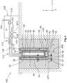
- FIG. 1 schematically shows a process water analysis arrangement 100 for continuously analyzing water samples of wastewater W.
- the wastewater W continuously flows into a wastewater tank 130 through a tank inlet, and continuously flows out of the wastewater tank 130 through a tank outlet, so that a general wastewater flow is generated within the wastewater tank 130.
- the wastewater tank 130 could be filled and emptied in intervals.
- the wastewater tank 130 can be a part of a wastewater treatment plant.
- the process water analysis arrangement 100 is provided for quasi-continuously determining the concentration of one or more analyte of the wastewater W, for example of ammonium and/or phosphate.
- the process water analysis arrangement 100 basically comprises a process water sampling immersion probe 10 which is completely immersed into the wastewater W and which is held in position by a stiff holding structure (not shown).
- the immersion probe 10 is fluidically, electrically and/or electronically connected to a land-based analyzer station 105 comprising an electric sample pump 132, an electric cleaning air pump 110, an electronic intermittent operation pump control 122 controlling the cleaning air pump 110, and an analyzer unit 120 for analyzing the concentration of one or more analyte of the water sample of the wastewater W.
- the immersion probe 10 is generally provided as a flat, plane and rectangular body substantially comprising a filter module 20 with two parallel vertical filter screens 24, 24', a cleaning air generator 40 arranged vertically directly adjacent to the vertical lower end of the filter module 20, and a flow guidance arrangement 30 having two vertical guidance walls 34, 34'.
- the two filter screens 24, 24' of the filter module 20 lie in a vertical plane yz, respectively, are parallel to each other and enclose, together with two vertical side walls 33, 33', a horizontal bottom wall 38 and a horizontal top wall 39, a rectangular filter module cavity 36.
- the housing of the filter module 20 has a sample exit opening 32 through which the filtered water sample is continuously pumped by the sample pump 132 to the analyzer unit 120 via a sample line 133.
- the analyzer unit 120 quasi-continuously determines the concentration of the respective analyte of the water sample.
- the cleaning air generator 40 is provided vertically close to the vertical lower end d24 of the two filter screens 24, 24' and is provided directly adjacent to the bottom wall 38 of the filter module housing.
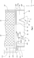
- the cleaning air generator 40 comprises a substantially rectangular bubble generator housing 41 with in total four air exit openings 51, 52.
- the opening planes p54 of the air exit openings 51, 52 lie in a vertical plane yz, respectively and lie substantially in the same vertical planes as the corresponding filter screens 24, 24'.
- the rectangular bubble generator housing 41 is provided with a horizontal top wall 42, two vertical end walls 46, 47 being parallel to each other, and two vertical side walls 44, 45, each side wall 44, 45 comprising two of the air exit openings 51, 52, as shown in figure 2 .
- the bubble generator housing 41 has an inverse cup-like structure, encloses a rectangular housing interior 60, has no bottom wall, and defines a horizontal housing bottom opening 50 having a horizontal housing opening plane p50.
- One end wall 47 of the bubble generator housing 41 is provided with a cleaning air inlet opening 141 through which pressurized cleaning air is pumped into the bubble generator housing interior 60 when the cleaning air pump 110 is running.
- cleaning air is sucked through a suction opening 126 and is pumped via a cleaning air line 111 to the cleaning air inlet opening 141.
- Two non-return valves 116, 117 are provided in the course of the cleaning air line 111, one non-return valve 116 being provided upstream of and adjacent to the cleaning air inlet opening 141, and the second non-return valve 117 downstream of and relatively close to the cleaning air pump 110.
- only one single non-return valve is necessary under normal circumstances, which is preferably the non-return verse 116 close to the cleaning air inlet opening 141.
- Every vertical bubble generator housing side wall 44, 45 is provided with two air exit openings 51, 52, respectively.
- the air exit openings 51, 52 are designed to become horizontally continuously wider in the vertical downward direction, as shown in figure 2 .
- the four air exit openings 51, 52 are identically shaped, and are substantially symmetrically inversely V-shaped with a total opening angle A of about 50°.
- Every air exit opening 51, 52 has a vertical opening plane p54.
- the horizontal opening top width wt54 at the opening's top end t54 is smaller than the opening down width wd54 at the opening's lower end d54, as shown in figure 2 .
- the edges 54 of the air exit openings 51, 52 transition into the horizontal opening edge of the horizontal housing bottom opening 50 of the bubble generator housing 41. As a result, the air exit openings 51, 52 are perfectly accessible in vertical direction y for manually cleaning the air exit openings 51, 52.
- the top ends or the top edges of the air exit openings 51, 52 have a vertical distance y54 of at least 2 cm below the lowest opening edge of the cleaning air inlet opening 141 of the bubble generator housing 41.
- the process water sampling immersion probe 10 is provided with a guidance arrangement 30 with two plane vertical guidance walls 34, 34' being parallel to each other and to the filter screens 24, 24'.
- Each guidance wall 34, 34' is horizontally spaced apart from the corresponding filter screen 24, 24' with a few centimeters thereby defining a vertical air bubble channel 28, 28' between the filter screen 24, 24' and the corresponding guiding wall 34, 34'.
- the linear lower end edges e34 of both guidance walls 34, 34' are vertically not above the air exit openings 51, 52 but are minimally below the lower ends d54 of the air exit openings 51, 52.
- the intermittent operation pump control 122 is provided with an operation schedule memory 123 memorizing an intermittent working schedule for the cleaning air pump 110.
- the intermittent operation pump control 122 controls the activity of the cleaning air pump 110 by switching the cleaning air pump 110 intermittently on and off, with an on-rate of, for example, 50% and an interval length of a complete on/off cycle of five minutes, for example.
- the activity of the cleaning air pump 110 can be controlled in a closed-loop control circuit including a clogging sensor for determining the clogging rate of the air exit openings 51, 52.
Landscapes
- Life Sciences & Earth Sciences (AREA)
- Hydrology & Water Resources (AREA)
- Physics & Mathematics (AREA)
- Health & Medical Sciences (AREA)
- Chemical & Material Sciences (AREA)
- Analytical Chemistry (AREA)
- Biochemistry (AREA)
- General Health & Medical Sciences (AREA)
- General Physics & Mathematics (AREA)
- Immunology (AREA)
- Pathology (AREA)
- Sampling And Sample Adjustment (AREA)
Priority Applications (2)
| Application Number | Priority Date | Filing Date | Title |
|---|---|---|---|
| EP23200354.1A EP4530600A1 (de) | 2023-09-28 | 2023-09-28 | Prozesswasserprobenahmeimmersionssonde |
| PCT/EP2024/075796 WO2025067928A1 (en) | 2023-09-28 | 2024-09-16 | Process water sampling immersion probe |
Applications Claiming Priority (1)
| Application Number | Priority Date | Filing Date | Title |
|---|---|---|---|
| EP23200354.1A EP4530600A1 (de) | 2023-09-28 | 2023-09-28 | Prozesswasserprobenahmeimmersionssonde |
Publications (1)
| Publication Number | Publication Date |
|---|---|
| EP4530600A1 true EP4530600A1 (de) | 2025-04-02 |
Family
ID=88236607
Family Applications (1)
| Application Number | Title | Priority Date | Filing Date |
|---|---|---|---|
| EP23200354.1A Pending EP4530600A1 (de) | 2023-09-28 | 2023-09-28 | Prozesswasserprobenahmeimmersionssonde |
Country Status (2)
| Country | Link |
|---|---|
| EP (1) | EP4530600A1 (de) |
| WO (1) | WO2025067928A1 (de) |
Citations (7)
| Publication number | Priority date | Publication date | Assignee | Title |
|---|---|---|---|---|
| US3795149A (en) * | 1971-10-15 | 1974-03-05 | Technicon Instr | Method and apparatus for supplying samples for automated analysis |
| US4138638A (en) * | 1974-09-06 | 1979-02-06 | Kabushiki Kaisha Meidensha | Apparatus for examining liquid quality |
| US6379621B1 (en) * | 1998-09-23 | 2002-04-30 | Wtw Wissenschaftlich-Technische Werkstaetten Gmbh | Apparatus for analyzing water and wastewater |
| DE102004037226B3 (de) | 2004-07-31 | 2005-08-18 | Dr. Bruno Lange Gmbh & Co. Kg | Probenentnahme-Tauchkörper |
| US20220099537A1 (en) * | 2020-09-30 | 2022-03-31 | Hach Lange Gmbh | Process water analysis sampling arrangement |
| US20220268755A1 (en) * | 2019-08-01 | 2022-08-25 | Hach Lange Gmbh | Water sampling immersion probe |
| EP4187226A1 (de) * | 2021-11-24 | 2023-05-31 | Hach Lange GmbH | Probenvorbereitungsanordnung |
-
2023
- 2023-09-28 EP EP23200354.1A patent/EP4530600A1/de active Pending
-
2024
- 2024-09-16 WO PCT/EP2024/075796 patent/WO2025067928A1/en active Pending
Patent Citations (7)
| Publication number | Priority date | Publication date | Assignee | Title |
|---|---|---|---|---|
| US3795149A (en) * | 1971-10-15 | 1974-03-05 | Technicon Instr | Method and apparatus for supplying samples for automated analysis |
| US4138638A (en) * | 1974-09-06 | 1979-02-06 | Kabushiki Kaisha Meidensha | Apparatus for examining liquid quality |
| US6379621B1 (en) * | 1998-09-23 | 2002-04-30 | Wtw Wissenschaftlich-Technische Werkstaetten Gmbh | Apparatus for analyzing water and wastewater |
| DE102004037226B3 (de) | 2004-07-31 | 2005-08-18 | Dr. Bruno Lange Gmbh & Co. Kg | Probenentnahme-Tauchkörper |
| US20220268755A1 (en) * | 2019-08-01 | 2022-08-25 | Hach Lange Gmbh | Water sampling immersion probe |
| US20220099537A1 (en) * | 2020-09-30 | 2022-03-31 | Hach Lange Gmbh | Process water analysis sampling arrangement |
| EP4187226A1 (de) * | 2021-11-24 | 2023-05-31 | Hach Lange GmbH | Probenvorbereitungsanordnung |
Also Published As
| Publication number | Publication date |
|---|---|
| WO2025067928A1 (en) | 2025-04-03 |
Similar Documents
| Publication | Publication Date | Title |
|---|---|---|
| US5192456A (en) | Apparatus for treating activated sludge and method of cleaning it | |
| KR20170048612A (ko) | 필터링 멤브레인용 가스 스파저 | |
| US6953529B2 (en) | Apparatus and method of particulate removal from liquids | |
| US12290763B2 (en) | Filter system for removing and/or neutralizing undissolved oil, grease, and salts and/or abraded metal particles on and in emulsions containing water | |
| DE102013211032A1 (de) | Filteranlage zum Entfernen und /oder Neutralisieren von ungelösten Ölen, Fetten und Salzen auf und in wasserhaltigen Emulsionen | |
| EP4530600A1 (de) | Prozesswasserprobenahmeimmersionssonde | |
| US12287316B2 (en) | Water sampling immersion probe | |
| CN112461600A (zh) | 一种水质检测预处理装置 | |
| JP4622575B2 (ja) | 気泡除去装置 | |
| US12287260B2 (en) | Process water analysis sampling arrangement | |
| EP4241021B1 (de) | Fehler erkennender luftreiniger | |
| JP2021506345A (ja) | 高効率のエアリフトポンプ | |
| RU2484880C2 (ru) | Способ и система для уменьшения числа частиц | |
| CN219657288U (zh) | 一种循环震荡水样的预处理装置 | |
| US3733906A (en) | Method and apparatus for the continuous withdrawal of samples from industrial process baths or the like for analysis | |
| CN216717970U (zh) | 水中油检测预处理系统和水中油检测系统 | |
| CN114216756B (zh) | 水中油检测系统 | |
| KR102360205B1 (ko) | 농축장치 및 방법 | |
| CN118341566A (zh) | 一种浆料磁滚机 | |
| CN113671106B (zh) | 铝酸钠溶液在线分析系统 | |
| CN222049682U (zh) | 取样装置和监测系统 | |
| CN217141482U (zh) | 超声波沉入式清洗设备 | |
| JP2012152669A (ja) | 膜分離装置の運転方法 | |
| CN219385133U (zh) | 一种生物过滤系统 | |
| CN220040440U (zh) | 一种打浆度测定仪 |
Legal Events
| Date | Code | Title | Description |
|---|---|---|---|
| PUAI | Public reference made under article 153(3) epc to a published international application that has entered the european phase |
Free format text: ORIGINAL CODE: 0009012 |
|
| STAA | Information on the status of an ep patent application or granted ep patent |
Free format text: STATUS: REQUEST FOR EXAMINATION WAS MADE |
|
| STAA | Information on the status of an ep patent application or granted ep patent |
Free format text: STATUS: EXAMINATION IS IN PROGRESS |
|
| 17P | Request for examination filed |
Effective date: 20240926 |
|
| AK | Designated contracting states |
Kind code of ref document: A1 Designated state(s): AL AT BE BG CH CY CZ DE DK EE ES FI FR GB GR HR HU IE IS IT LI LT LU LV MC ME MK MT NL NO PL PT RO RS SE SI SK SM TR |
|
| 17Q | First examination report despatched |
Effective date: 20250312 |