EP4530489A1 - Palier aérodynamique hybride à amortissement actif - Google Patents
Palier aérodynamique hybride à amortissement actif Download PDFInfo
- Publication number
- EP4530489A1 EP4530489A1 EP24190392.1A EP24190392A EP4530489A1 EP 4530489 A1 EP4530489 A1 EP 4530489A1 EP 24190392 A EP24190392 A EP 24190392A EP 4530489 A1 EP4530489 A1 EP 4530489A1
- Authority
- EP
- European Patent Office
- Prior art keywords
- shaft
- components
- stationary
- bearing
- motor
- Prior art date
- Legal status (The legal status is an assumption and is not a legal conclusion. Google has not performed a legal analysis and makes no representation as to the accuracy of the status listed.)
- Pending
Links
Images




Classifications
-
- F—MECHANICAL ENGINEERING; LIGHTING; HEATING; WEAPONS; BLASTING
- F16—ENGINEERING ELEMENTS AND UNITS; GENERAL MEASURES FOR PRODUCING AND MAINTAINING EFFECTIVE FUNCTIONING OF MACHINES OR INSTALLATIONS; THERMAL INSULATION IN GENERAL
- F16C—SHAFTS; FLEXIBLE SHAFTS; ELEMENTS OR CRANKSHAFT MECHANISMS; ROTARY BODIES OTHER THAN GEARING ELEMENTS; BEARINGS
- F16C17/00—Sliding-contact bearings for exclusively rotary movement
- F16C17/02—Sliding-contact bearings for exclusively rotary movement for radial load only
- F16C17/024—Sliding-contact bearings for exclusively rotary movement for radial load only with flexible leaves to create hydrodynamic wedge, e.g. radial foil bearings
-
- F—MECHANICAL ENGINEERING; LIGHTING; HEATING; WEAPONS; BLASTING
- F16—ENGINEERING ELEMENTS AND UNITS; GENERAL MEASURES FOR PRODUCING AND MAINTAINING EFFECTIVE FUNCTIONING OF MACHINES OR INSTALLATIONS; THERMAL INSULATION IN GENERAL
- F16C—SHAFTS; FLEXIBLE SHAFTS; ELEMENTS OR CRANKSHAFT MECHANISMS; ROTARY BODIES OTHER THAN GEARING ELEMENTS; BEARINGS
- F16C32/00—Bearings not otherwise provided for
- F16C32/04—Bearings not otherwise provided for using magnetic or electric supporting means
- F16C32/0406—Magnetic bearings
- F16C32/0408—Passive magnetic bearings
-
- F—MECHANICAL ENGINEERING; LIGHTING; HEATING; WEAPONS; BLASTING
- F16—ENGINEERING ELEMENTS AND UNITS; GENERAL MEASURES FOR PRODUCING AND MAINTAINING EFFECTIVE FUNCTIONING OF MACHINES OR INSTALLATIONS; THERMAL INSULATION IN GENERAL
- F16C—SHAFTS; FLEXIBLE SHAFTS; ELEMENTS OR CRANKSHAFT MECHANISMS; ROTARY BODIES OTHER THAN GEARING ELEMENTS; BEARINGS
- F16C32/00—Bearings not otherwise provided for
- F16C32/04—Bearings not otherwise provided for using magnetic or electric supporting means
- F16C32/0402—Bearings not otherwise provided for using magnetic or electric supporting means combined with other supporting means, e.g. hybrid bearings with both magnetic and fluid supporting means
-
- F—MECHANICAL ENGINEERING; LIGHTING; HEATING; WEAPONS; BLASTING
- F16—ENGINEERING ELEMENTS AND UNITS; GENERAL MEASURES FOR PRODUCING AND MAINTAINING EFFECTIVE FUNCTIONING OF MACHINES OR INSTALLATIONS; THERMAL INSULATION IN GENERAL
- F16C—SHAFTS; FLEXIBLE SHAFTS; ELEMENTS OR CRANKSHAFT MECHANISMS; ROTARY BODIES OTHER THAN GEARING ELEMENTS; BEARINGS
- F16C32/00—Bearings not otherwise provided for
- F16C32/04—Bearings not otherwise provided for using magnetic or electric supporting means
- F16C32/0406—Magnetic bearings
- F16C32/0408—Passive magnetic bearings
- F16C32/0423—Passive magnetic bearings with permanent magnets on both parts repelling each other
- F16C32/0425—Passive magnetic bearings with permanent magnets on both parts repelling each other for radial load mainly
-
- F—MECHANICAL ENGINEERING; LIGHTING; HEATING; WEAPONS; BLASTING
- F16—ENGINEERING ELEMENTS AND UNITS; GENERAL MEASURES FOR PRODUCING AND MAINTAINING EFFECTIVE FUNCTIONING OF MACHINES OR INSTALLATIONS; THERMAL INSULATION IN GENERAL
- F16C—SHAFTS; FLEXIBLE SHAFTS; ELEMENTS OR CRANKSHAFT MECHANISMS; ROTARY BODIES OTHER THAN GEARING ELEMENTS; BEARINGS
- F16C39/00—Relieving load on bearings
- F16C39/06—Relieving load on bearings using magnetic means
- F16C39/063—Permanent magnets
- F16C39/066—Permanent magnets with opposing permanent magnets repelling each other
-
- H—ELECTRICITY
- H02—GENERATION; CONVERSION OR DISTRIBUTION OF ELECTRIC POWER
- H02K—DYNAMO-ELECTRIC MACHINES
- H02K7/00—Arrangements for handling mechanical energy structurally associated with dynamo-electric machines, e.g. structural association with mechanical driving motors or auxiliary dynamo-electric machines
- H02K7/08—Structural association with bearings
- H02K7/09—Structural association with bearings with magnetic bearings
-
- F—MECHANICAL ENGINEERING; LIGHTING; HEATING; WEAPONS; BLASTING
- F16—ENGINEERING ELEMENTS AND UNITS; GENERAL MEASURES FOR PRODUCING AND MAINTAINING EFFECTIVE FUNCTIONING OF MACHINES OR INSTALLATIONS; THERMAL INSULATION IN GENERAL
- F16C—SHAFTS; FLEXIBLE SHAFTS; ELEMENTS OR CRANKSHAFT MECHANISMS; ROTARY BODIES OTHER THAN GEARING ELEMENTS; BEARINGS
- F16C2326/00—Articles relating to transporting
- F16C2326/01—Parts of vehicles in general
-
- F—MECHANICAL ENGINEERING; LIGHTING; HEATING; WEAPONS; BLASTING
- F16—ENGINEERING ELEMENTS AND UNITS; GENERAL MEASURES FOR PRODUCING AND MAINTAINING EFFECTIVE FUNCTIONING OF MACHINES OR INSTALLATIONS; THERMAL INSULATION IN GENERAL
- F16C—SHAFTS; FLEXIBLE SHAFTS; ELEMENTS OR CRANKSHAFT MECHANISMS; ROTARY BODIES OTHER THAN GEARING ELEMENTS; BEARINGS
- F16C2360/00—Engines or pumps
- F16C2360/44—Centrifugal pumps
-
- F—MECHANICAL ENGINEERING; LIGHTING; HEATING; WEAPONS; BLASTING
- F16—ENGINEERING ELEMENTS AND UNITS; GENERAL MEASURES FOR PRODUCING AND MAINTAINING EFFECTIVE FUNCTIONING OF MACHINES OR INSTALLATIONS; THERMAL INSULATION IN GENERAL
- F16C—SHAFTS; FLEXIBLE SHAFTS; ELEMENTS OR CRANKSHAFT MECHANISMS; ROTARY BODIES OTHER THAN GEARING ELEMENTS; BEARINGS
- F16C2360/00—Engines or pumps
- F16C2360/46—Fans, e.g. ventilators
-
- F—MECHANICAL ENGINEERING; LIGHTING; HEATING; WEAPONS; BLASTING
- F16—ENGINEERING ELEMENTS AND UNITS; GENERAL MEASURES FOR PRODUCING AND MAINTAINING EFFECTIVE FUNCTIONING OF MACHINES OR INSTALLATIONS; THERMAL INSULATION IN GENERAL
- F16C—SHAFTS; FLEXIBLE SHAFTS; ELEMENTS OR CRANKSHAFT MECHANISMS; ROTARY BODIES OTHER THAN GEARING ELEMENTS; BEARINGS
- F16C2362/00—Apparatus for lighting or heating
- F16C2362/52—Compressors of refrigerators, e.g. air-conditioners
Definitions
- the present disclosure relates to bearings and, in particular, to hybrid airfoil bearings with active damping.
- a foil bearing also known as a foil-air bearing or airfoil bearing, is a type of air bearing.
- a shaft is supported by a compliant, spring-loaded foil journal lining. Once the shaft is spinning fast enough, the working fluid (usually air) pushes the foil away from the shaft so that no contact occurs.
- the shaft and foil are separated by high-pressure air, which is generated by the rotation that pulls gas into the bearing via viscosity effects. The high speed of the shaft with respect to the foil is required to initiate the air gap, and once this has been achieved, no wear occurs.
- foil bearings require no external pressurization system for the working fluid, so the hydrodynamic bearing is self-starting.
- a hybrid bearing assembly includes stationary components, a shaft disposed to rotate relative to the stationary components, passive magnetic bearing components integrated into the shaft and the stationary components to generate passive magnetic force to resist radial movement of the shaft relative to the stationary components and an active damping system.
- the active damping system includes a stationary coil, a magnetic element rotatable with the shaft to induce current in the stationary coil and a circuit electrically coupled with the stationary coil.
- the circuit is configured to determine from the current an attitude change of the shaft and the magnetic element and to apply damping current to the stationary coil to resist the attitude change.
- the airfoil bearing components include a top foil immediately surrounding the shaft and the passive magnetic bearing components remove a static load of the shaft on the top foil.
- the stationary coil is provided as one or more velocity sensing coils.
- the circuit is a transconductance amplified circuit.
- the attitude change includes the radial movement of the shaft and the damping current generates a magnetic flux that interacts with the magnetic element to damp the attitude change.
- the circuit is further configured to apply the damping current to the stationary coil to damp rotor-dynamic frequency modes.
- the circuit is further configured to ignore unbalanced excitations of the shaft.
- the hybrid bearing assembly is incorporated into one or more of a thrust bearing and a journal bearing.
- a motor includes stationary housing components, a shaft disposed to rotate relative to the stationary housing components and a hybrid bearing assembly configured to maintain a radial position of the shaft relative to the stationary housing components.
- the hybrid bearing assembly includes passive magnetic bearing components integrated into the shaft and the stationary housing components to generate passive magnetic force to resist radial movement of the shaft relative to the stationary housing components and an active damping system.
- the active damping system includes a stationary coil, a magnetic element rotatable with the shaft to induce current in the stationary coil and a circuit electrically coupled with the stationary coil.
- the circuit is configured to determine from the current an attitude change of the shaft and the magnetic element and to apply damping current to the stationary coil to resist the attitude change.
- the attitude change includes the radial movement of the shaft and the damping current generates a magnetic flux that interacts with the magnetic element to damp the attitude change.
- the circuit is further configured to apply the damping current to the stationary coil to damp rotor-dynamic frequency modes and to ignore unbalanced excitations of the shaft.
- a vehicle including the motor is provided and the motor is a motor of one or more of a cabin air compressor, a fan and a pump.
- a vehicle including the motor is provided and the motor is a motor of an air cycle machine (ACM).
- ACM air cycle machine
- a motor includes stationary housing components, a shaft disposed to rotate relative to the stationary housing components and a hybrid bearing assembly configured to maintain a radial position of the shaft relative to the stationary housing components.
- the hybrid bearing assembly includes passive magnetic bearing components integrated into the shaft and the stationary housing components to generate passive magnetic force to resist radial movement of the shaft relative to the stationary housing components, airfoil bearing components to supplement the passive magnetic bearing components and an active damping system.
- the active damping system includes a stationary coil, a magnetic element rotatable with the shaft to induce current in the stationary coil and a circuit electrically coupled with the stationary coil. The circuit is configured to determine from the current an attitude change of the shaft and the magnetic element and to apply damping current to the stationary coil to resist the attitude change.
- the attitude change includes the radial movement of the shaft and the damping current generates a magnetic flux that interacts with the magnetic element to damp the attitude change.
- the circuit is further configured to apply the damping current to the stationary coil to damp rotor-dynamic frequency modes and to ignore unbalanced excitations of the shaft.
- the airfoil bearing components include a top foil immediately surrounding the shaft and the passive magnetic bearing components remove a static load of the shaft on the top foil.
- a vehicle including motor is provided and the motor is a motor of one or more of a cabin air compressor, a fan and a pump.
- a vehicle including the motor is provided and the motor is a motor of an air cycle machine (ACM).
- ACM air cycle machine
- Airfoil bearings have certain limitations. These include a minimum speed to activate, sensitivity to damage due to metal-to-metal contact and/or inadequate thermal management. Active magnetic bearings resolve many of these issues, but have added cost and weight as well as a need for circuitry to provide current for the electromagnet. In addition, it has been observed that permanent magnetic (PM) bearings tend to have no or limited damping and hybridization of PM and gas foil bearings (GFB) can be complicated due to the limited damping provided by GFB.
- PM permanent magnetic
- GFB gas foil bearings
- This new type of hybrid airfoil bearing is based on the three technologies: airfoil bearings, PM bearings and active electromagnetic damping.
- the novel solution addresses the problems of PM bearings, such as weak damping or large eccentricity.
- electromagnetic damping provides complementary damping.
- a hybrid airfoil bearing 101 is provided for use with a shaft 112.
- the hybrid airfoil bearing 101 includes airfoil bearing components 110 and passive magnetic bearing components 120 that are integrated into the shaft 112 and the airfoil bearing components 110.
- the passive magnetic bearing components 120 can include or be provided with magnetic material that tends to retain its magnetic characteristics during high-temperature and high-pressure operations associated with aviation motors of an aircraft and air cycle machines (ACMs). that are integrated into the shaft 112 and the airfoil bearing components 110
- the airfoil bearing components 110 include a top foil 1161 (see below) that immediately surrounds the shaft 112 and stationary components that define an inner bore 111.
- the shaft 112 is rotatable about a longitudinal axis A thereof within the inner bore 111 and relative to the stationary components.
- the stationary components include a housing 113, such as a motor housing, that defines an outer bore 1131 and a bearing sleeve 114 that is supported within the outer bore 1131.
- the stationary components further include elastomeric O-rings 115, by which the bearing sleeve 114 is supported within the outer bore 1131, and one or more foils 116 for supporting the shaft 112.
- the one or more foils 116 include the top foil 1161 and a corrugated bump foil 1162 surrounding the top foil 1161. With the top foil 1161 immediately surrounding the shaft 112, the bump foil 1162 immediately surrounds the top foil 1161.
- the one or more foils 116 can each include or be provided with high magnetic permeability materials. Additionally or alternatively, the one or more foils 116 can each be provided as a mesh.
- the stationary components can also include one more filters that prevent particles, such as magnetic particles, from becoming trapped in the hybrid airfoil bearing 101.
- the shaft 112 During operation of the airfoil bearing components, if not for the presence of the passive magnetic bearing components 120, the shaft 112 would be supported as a static load by the one or more foils 116 (i.e., the top foil 1161) until the shaft 112 begins spinning or rotating fast enough for working fluid (i.e., air) to push the shaft 112 away from the one or more foils 116 so that no contact occurs.
- working fluid i.e., air
- the passive magnetic bearing components 120 serve as auxiliary magnetic bearings to remove the static load of the shaft 112 on the top foil 1161 and to provide for auxiliary rotor or shaft support and emergency operation backup. For example, in case of a temporary loss of capacity due to low-speed rotation, rotor imbalance (surging), etc., the passive magnetic bearing components 120 would eliminate or reduce the chances of unit damage due to failure of the airfoil bearing components 110 maintaining separation of the shaft 112 and at least the top foil 1161 of the one or more foils 116. The passive magnetic bearing components 120 generate a repulsion force between the shaft 112 and at least the top foil 1161 of the one or more foils 116.
- This repulsion force is proportional to an inverse of a distance between the respective bearing surfaces of the shaft 112 and at least the top foil 1161 of the one or more foils 116 and becomes significant when the shaft 112 deviates from its centered (axial and/or radial) location.
- the passive magnetic bearing components 120 are integrated into the shaft 112 and the airfoil bearing components 110, the hybrid airfoil bearing 101 can be manufactured easily and without extensive additional costs.
- the shaft 112 can be provided as an elongate dipole magnet 1120 with a first end 131 and a second end 132 that is opposite the first end 131.
- the shaft 112 includes first magnetic materials 141 having a first magnetic pole.
- the shaft 112 includes second magnetic materials 142 having a second magnetic pole, which is opposite the first magnetic pole.
- At least one of the stationary components can be provided as an elongate dipole magnet 1140 that surrounds the shaft 112 with a first end 151 corresponding to the first end 131 and a second end 152, which is opposite the first end 151 and corresponds to the second end 132.
- the bearing sleeve 114 includes third magnetic materials 163 having the first magnetic pole.
- the bearing sleeve 114 includes fourth magnetic materials 164 having the second magnetic pole.
- the description provided herein is distinguished from conventional cases in which an elongate dipole magnet is attached to or about a shaft. That is, in those conventional cases, passive magnetic components are not integrated into a shaft whereas in the description provided herein the passive magnet components 120 are integrated into the shaft 112 to form the shaft 112 into the elongate dipole magnet 1120.
- the passive magnetic materials in the shaft 112 and the bearing sleeve 114 can be segmented along an entirety of the circumferential dimension of the shaft 112 and the bearing sleeve 114 and/or localized at one or more circumferential sections of the shaft 112 and the bearing sleeve 114 so that when the shaft 112 comes to rest, the one or more circumferential sections of the shaft 112 and the bearing sleeve 114 align in the vertical direction and remove the load of the shaft 112 on the one or more foils 116 in opposition to the force of gravity.
- the hybrid airfoil bearing 101 is provided with a similar overall configuration as the configuration described above but with a different passive magnetic arrangement. The following description will thus omit the details of the hybrid airfoil bearing 101 of FIGS. 2A and 2B that are already described above.
- the shaft 112 includes an outer ring of magnetic materials 170 integrated therein and having a first magnetic pole and optionally an inner core of magnetic materials having a second magnetic pole and the bearing sleeve 114 includes an inner ring of magnetic materials 171 having the first magnetic pole and an outer ring of magnetic materials having the second magnetic pole.
- passive magnetic repulsion of the outer ring of magnetic materials 171 and the inner ring of magnetic materials 170 suspends the shaft 112 within the inner bore 111 and maintains separation between the shaft 112 and both the bearing sleeve 114 and the one or more foils 116.
- the shaft 112 can further include a hollow interior within the outer ring of magnetic materials 170 or an inner ring of magnetic materials that is either of a same pole as the outer ring of magnetic materials 170 or an opposite pole as the outer ring of magnetic materials 170. In any case, the shaft 112 does not include any portion formed of non-magnetic materials.
- the passive magnetic materials in the shaft 112 and the bearing sleeve 114 can be segmented along an entirety of the circumferential dimension of the shaft 112 and the bearing sleeve 114 and/or localized at one or more circumferential sections of the shaft 112 and the bearing sleeve 114 so that when the shaft 112 comes to rest, the one or more circumferential sections of the shaft 112 and the bearing sleeve 114 align in the vertical direction and remove the load of the shaft 112 on the one or more foils 116 in opposition to the force of gravity.
- the description provided herein is distinguished from conventional cases in which a ring of passive magnetic materials is attached to or about a shaft of non-magnetic materials. That is, in those conventional cases, passive magnetic components are not integrated into a shaft whereas in the description provided herein the outer ring of magnetic materials 170 are integrated into the shaft 112.
- the shaft 112 and both the bearing sleeve 114 and the one or more foils 116 are respectively configured for passive magnetic repulsion of one another to suspend the shaft 112 within the inner bore 111 and to act as an auxiliary bearing for the airfoil bearing components 110.
- the magnetic materials of the embodiments of FIGS. 1A, 1B and 1C and the magnetic materials of the embodiments of FIGS. 2A and 2B may exhibit variable magnetization in circumferential, axial and/or radial dimensions to accommodate and/or account for possible variable attitude angles of the hybrid airfoil bearing 101.
- a device 301 is provided as an aviation motor of an aircraft and includes a housing 310, a stator 320, a rotor 330 that is rotatable within the housing 310 and one or more hybrid airfoil bearings 340.
- the stator 320 is configured to generate magnetic flux to drive rotation of the rotor 330.
- the one or more hybrid airfoil bearings 340 can be provided as first and second hybrid airfoil bearings 3401 and 3402. Each of the first and second hybrid airfoil bearings 3401 and 3402 is configured as described above with reference to FIGS. 1A, 1B and 1C or FIGS. 2A and 2B .
- a device 401 is provided as an ACM and includes a housing 410, a rotor 420 that is rotatable within the housing 410 and one or more hybrid airfoil bearings 430.
- the one or more hybrid airfoil bearings 430 can be provided as an axially oriented hybrid airfoil bearing 4301 (see FIG. 4 ) and a radially oriented hybrid airfoil bearing 4302 (see FIG. 5 ).
- Each of the axially oriented hybrid airfoil bearing 4301 and the radially oriented hybrid airfoil bearing 4302 is configured as described above with reference to FIGS. 1A, 1B and 1C or FIGS. 2A and 2B .
- the various sleeves described above can be integrated into the ACM.
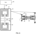
- the hybrid bearing assembly 601 includes many features described in detail above, which will be apparent to a person of skill in the art and which need not be described again below.
- the hybrid bearing assembly 601 includes stationary components 610, a shaft 620 that is disposed to rotate about a rotational axis A thereof relative to the stationary components 610, passive magnetic bearing components 630 and an active damping system 640.
- the passive magnetic bearing components 630 are integrated into the shaft 620 and the stationary components 610 to generate passive magnetic force to resist radial movement of the shaft 620 relative to the stationary components 610.
- the active damping system 640 includes a stationary coil 641, which can be provided as one or more velocity sensing coils, a magnetic element 642 and a circuit 643.
- the magnetic element 642 is coupled to or integrated with the shaft 620 and, in some cases, can also be generally proximate to the stationary coil 641. As such, the magnetic element 642 is rotatable with the shaft 620 to thereby induce current in the stationary coil 641.
- the circuit 643 can be provided as a transconductance amplified circuit and is electrically coupled with the stationary coil 641.
- the circuit 643 is configured to determine from the current induced in the stationary coil 641 an attitude change of the shaft 620 and the magnetic element 642 and to apply damping current to the stationary coil 641 to resist the attitude change.
- the attitude change of the shaft 620 and the magnetic element 642 can be the radial movement of the shaft 620 relative to the stationary components 610.
- the damping current applied to the stationary coil 641 by the circuit 643 generates a magnetic flux that interacts with the magnetic element 642 to damp the attitude change.
- the circuit 643 can be further configured to apply the damping current to the stationary coil 641 to damp rotor-dynamic frequency modes and/or can be configured to ignore unbalanced excitations of the shaft 620 at relatively high rotational speeds.
- the hybrid bearing assembly 601 of FIG. 6 can further include airfoil bearing components 650, as described above, to supplement the passive magnetic bearing components 630.
- the airfoil bearing components 650 can include a top foil (i.e., the top foil 1161 of FIGS. 1A and 2A ) immediately surrounding the shaft 620 and the passive magnetic bearing components 630 can be disposed and configured to remove a static load of the shaft 620 on the top foil.
- the hybrid bearing assembly 601 of FIG. 6 can be incorporated into one or more of a thrust bearing 701 as shown in FIG. 7 and a journal bearing 801 as shown in FIG. 8 .
- the hybrid airfoil bearing 601 of FIG. 6 can be provided for use in a motor 602 as shown in FIG. 6 .
- the stationary components 610 are stationary housing components of the motor 602
- the shaft 620 is disposed to rotate relative to the stationary housing components (the stationary components 610) and the hybrid bearing assembly 601 is configured to maintain a radial position of the shaft 620 relative to the stationary housing components (the stationary components 610).
- the motor 602 can be incorporated into a vehicle, such as an aircraft, as a component of the vehicle with the motor 602 being a motor 602 of one or more of a cabin air compressor, a fan and a pump and/or with the motor 602 being a motor 602 of an ACM.
- the hybrid bearing assembly 601 can optionally include the above-described airfoil bearing components 650 to supplement the passive magnetic bearing components 630.
Landscapes
- Engineering & Computer Science (AREA)
- General Engineering & Computer Science (AREA)
- Mechanical Engineering (AREA)
- Power Engineering (AREA)
- Physics & Mathematics (AREA)
- Fluid Mechanics (AREA)
- Magnetic Bearings And Hydrostatic Bearings (AREA)
Applications Claiming Priority (1)
| Application Number | Priority Date | Filing Date | Title |
|---|---|---|---|
| US18/362,669 US12584521B2 (en) | 2023-07-31 | 2023-07-31 | Hybrid airfoil bearing with active damping |
Publications (1)
| Publication Number | Publication Date |
|---|---|
| EP4530489A1 true EP4530489A1 (fr) | 2025-04-02 |
Family
ID=91967073
Family Applications (1)
| Application Number | Title | Priority Date | Filing Date |
|---|---|---|---|
| EP24190392.1A Pending EP4530489A1 (fr) | 2023-07-31 | 2024-07-23 | Palier aérodynamique hybride à amortissement actif |
Country Status (2)
| Country | Link |
|---|---|
| US (1) | US12584521B2 (fr) |
| EP (1) | EP4530489A1 (fr) |
Families Citing this family (1)
| Publication number | Priority date | Publication date | Assignee | Title |
|---|---|---|---|---|
| US12480544B2 (en) | 2023-06-08 | 2025-11-25 | Hamilton Sundstrand Corporation | Hybrid airfoil and auxiliary magnetic bearings |
Citations (4)
| Publication number | Priority date | Publication date | Assignee | Title |
|---|---|---|---|---|
| US4444444A (en) * | 1981-08-17 | 1984-04-24 | Societe Nationale Industrielle Aerospatiale | Equipment for storage of energy under kinetic form and recovery thereof in electric form and method of using such equipment |
| US5519274A (en) * | 1994-09-07 | 1996-05-21 | Rotodynamics-Seal Research, Inc. | Magnetically active foil bearing |
| JPH0921420A (ja) * | 1995-07-06 | 1997-01-21 | Osaka Shinku Kiki Seisakusho:Kk | 高速回転機械の磁気軸受装置 |
| US6877963B2 (en) * | 2000-09-02 | 2005-04-12 | Leybold Vakuum Gmbh | Vacuum pump |
Family Cites Families (34)
| Publication number | Priority date | Publication date | Assignee | Title |
|---|---|---|---|---|
| US3614181A (en) | 1970-07-02 | 1971-10-19 | Us Air Force | Magnetic bearing for combined radial and thrust loads |
| DE2457783C2 (de) * | 1974-12-06 | 1986-10-09 | Arthur Pfeiffer Vakuumtechnik Wetzlar Gmbh, 6334 Asslar | Magnetische Lagerung |
| CH611990A5 (fr) | 1977-01-17 | 1979-06-29 | Sulzer Ag | |
| GB2268983B (en) | 1992-07-23 | 1996-04-03 | Glacier Metal Co Ltd | Magnetic bearing back-up |
| EP0687827A1 (fr) | 1994-06-13 | 1995-12-20 | Mechanical Technology Incorporated | Palier magnétique hybride feuilles/gaz |
| WO1997002437A1 (fr) | 1995-06-30 | 1997-01-23 | Alliedsignal Inc. | Palier hybride a feuille et magnetique |
| US5726560A (en) | 1995-09-01 | 1998-03-10 | Barber-Colman Company | Switched reluctance generator |
| US5894181A (en) | 1997-07-18 | 1999-04-13 | Imlach; Joseph | Passive magnetic bearing system |
| US6965181B1 (en) | 1997-09-15 | 2005-11-15 | Mohawk Innovative Technology, Inc. | Hybrid foil-magnetic bearing with improved load sharing |
| JP2004084877A (ja) | 2002-08-28 | 2004-03-18 | Honda Motor Co Ltd | フォイル軸受け |
| BRPI0511385A (pt) | 2004-06-15 | 2007-12-04 | Aly El-Shafei | métodos para controlar a instabilidade em rolamentos de pelìcula de fluido |
| WO2007011366A2 (fr) | 2004-08-16 | 2007-01-25 | Satcon Technology Corporation | Palier magnetique/a feuilles integre et procedes de support d'une fusee d'arbre utilisant ce dernier |
| JP2007092646A (ja) * | 2005-09-29 | 2007-04-12 | Jtekt Corp | 燃料電池用過給機 |
| JP4788351B2 (ja) | 2006-01-19 | 2011-10-05 | 株式会社ジェイテクト | 燃料電池用過給機 |
| JP2009014084A (ja) | 2007-07-03 | 2009-01-22 | Jtekt Corp | 軸受装置およびこれを備えた遠心圧縮機 |
| KR100928948B1 (ko) | 2007-10-23 | 2009-11-30 | 한국과학기술연구원 | 공기포일-마그네틱 하이브리드 베어링 및 그 제어시스템 |
| TWI359908B (en) | 2008-12-24 | 2012-03-11 | Ind Tech Res Inst | Oil-free centrifugal blade compressor and magnetic |
| US8959944B2 (en) * | 2009-08-19 | 2015-02-24 | George Samuel Levy | Centrifugal Air Cycle Air Conditioner |
| US8531071B2 (en) | 2009-12-28 | 2013-09-10 | Rolls-Royce Corporation | Turbine engine powered system with hybrid bearing |
| EP2589827A1 (fr) | 2011-11-04 | 2013-05-08 | ETH Zürich | Machine électrique rotative et procédé pour mesurer un déplacement d'une machine électrique rotative |
| GB201122142D0 (en) | 2011-12-21 | 2012-02-01 | Venus Systems Ltd | Centrifugal compressors |
| US9234522B2 (en) | 2012-01-03 | 2016-01-12 | United Technologies Corporation | Hybrid bearing turbomachine |
| WO2016140426A1 (fr) | 2015-03-04 | 2016-09-09 | 한국에너지기술연구원 | Palier magnétique passif hybride |
| FR3045111B1 (fr) | 2015-12-14 | 2017-12-01 | Labinal Power Systems | Compresseur centrifuge electrique de turbomachine ou d'aeronef |
| US10634154B2 (en) | 2016-07-25 | 2020-04-28 | Daikin Applied Americas Inc. | Centrifugal compressor and magnetic bearing backup system for centrifugal compressor |
| US10385915B2 (en) | 2016-08-16 | 2019-08-20 | Hamilton Sundstrand Corporation | High load capacity hybrid foil bearing |
| CN108868892B (zh) | 2018-01-12 | 2024-04-02 | 刘慕华 | 一种转子系统及其控制方法和燃气轮机发电机组及其控制方法 |
| CN111102293A (zh) | 2020-01-18 | 2020-05-05 | 湖南大学 | 主被动磁气混合轴承 |
| JP7392620B2 (ja) | 2020-09-30 | 2023-12-06 | 株式会社豊田自動織機 | 遠心圧縮機 |
| CN115199705B (zh) | 2022-05-31 | 2023-06-16 | 北京信息科技大学 | 具有阻尼能量回收和在线模态监测的多功能储能飞轮系统 |
| KR102871583B1 (ko) | 2022-06-17 | 2025-10-22 | 한국과학기술연구원 | 마그네틱 베어링, 영구자석 및 슬리브 저널 베어링으로 구성된 하이브리드 베어링 구조를 갖는 터보기기 및 그 제어방법 |
| US12480544B2 (en) | 2023-06-08 | 2025-11-25 | Hamilton Sundstrand Corporation | Hybrid airfoil and auxiliary magnetic bearings |
| US20250084860A1 (en) | 2023-09-11 | 2025-03-13 | Hamilton Sundstrand Corporation | Compressor assembly with hybrid airfoil and auxiliary magnetic bearings |
| US20250084899A1 (en) | 2023-09-11 | 2025-03-13 | Hamilton Sundstrand Corporation | Air cycle machine (acm) with hybrid airfoil and auxiliary magnetic thrust bearings |
-
2023
- 2023-07-31 US US18/362,669 patent/US12584521B2/en active Active
-
2024
- 2024-07-23 EP EP24190392.1A patent/EP4530489A1/fr active Pending
Patent Citations (4)
| Publication number | Priority date | Publication date | Assignee | Title |
|---|---|---|---|---|
| US4444444A (en) * | 1981-08-17 | 1984-04-24 | Societe Nationale Industrielle Aerospatiale | Equipment for storage of energy under kinetic form and recovery thereof in electric form and method of using such equipment |
| US5519274A (en) * | 1994-09-07 | 1996-05-21 | Rotodynamics-Seal Research, Inc. | Magnetically active foil bearing |
| JPH0921420A (ja) * | 1995-07-06 | 1997-01-21 | Osaka Shinku Kiki Seisakusho:Kk | 高速回転機械の磁気軸受装置 |
| US6877963B2 (en) * | 2000-09-02 | 2005-04-12 | Leybold Vakuum Gmbh | Vacuum pump |
Also Published As
| Publication number | Publication date |
|---|---|
| US12584521B2 (en) | 2026-03-24 |
| US20250043821A1 (en) | 2025-02-06 |
Similar Documents
| Publication | Publication Date | Title |
|---|---|---|
| US12480544B2 (en) | Hybrid airfoil and auxiliary magnetic bearings | |
| EP4520986A1 (fr) | Machine à cycle d'air (acm) avec palier hybride aérodynamique et paliers axiales magnétiques auxiliaires | |
| EP4524414A1 (fr) | Ensemble compresseur avec palier hybride aérodynamique à feuille et paliers magnétiques auxiliaires | |
| CN108869558B (zh) | 一种轴承、转子系统及轴承的控制方法 | |
| AU2002326878B2 (en) | Flywheel energy storage systems | |
| US5021697A (en) | Auxiliary bearing design for active magnetic bearings | |
| JP2001511498A (ja) | 流体機械のロータ用軸受装置およびその使用方法 | |
| EP2784326B1 (fr) | Turbomachine compact à paliers magnétiques et paliers auxiliaires | |
| CN108869542B (zh) | 一种推力轴承、转子系统及推力轴承的控制方法 | |
| US20140232226A1 (en) | High conical angle touch down bearing | |
| US20150275911A1 (en) | Compact turbomachine with magnetic bearings and auxiliary bearings | |
| EP1350035B1 (fr) | Palier a film d'huile a feuille souple dote d'un amortisseur a courant de foucault | |
| US12584521B2 (en) | Hybrid airfoil bearing with active damping | |
| US8760021B2 (en) | Centrifugally decoupling touchdown bearings | |
| CN101482149A (zh) | 一种特性可控的主动电磁轴承的备用轴承装置 | |
| SE508445C2 (sv) | Vakuumpump av höghastighetstyp | |
| JPH08178011A (ja) | フライホイール装置 | |
| EP0693630A2 (fr) | Pallier magnétique axial | |
| CN208123273U (zh) | 一种轴承和转子系统 | |
| CN107040082B (zh) | 一种磁悬浮反作用飞轮装置 | |
| JPH1137155A (ja) | 磁気軸受およびその制御系 | |
| Nakajima et al. | Three-axis active control magnetic bearing with asymmetric structure for high-temperature machines | |
| JP2001041241A (ja) | 超電導磁気浮上装置、超電導電力貯蔵方法および超電導磁気軸受試験方法 | |
| CN106712365A (zh) | 组合轴承磁悬浮电动机/电主轴 | |
| Swanson et al. | Performance of a foil-magnetic hybrid bearing |
Legal Events
| Date | Code | Title | Description |
|---|---|---|---|
| PUAI | Public reference made under article 153(3) epc to a published international application that has entered the european phase |
Free format text: ORIGINAL CODE: 0009012 |
|
| STAA | Information on the status of an ep patent application or granted ep patent |
Free format text: STATUS: THE APPLICATION HAS BEEN PUBLISHED |
|
| AK | Designated contracting states |
Kind code of ref document: A1 Designated state(s): AL AT BE BG CH CY CZ DE DK EE ES FI FR GB GR HR HU IE IS IT LI LT LU LV MC ME MK MT NL NO PL PT RO RS SE SI SK SM TR |
|
| STAA | Information on the status of an ep patent application or granted ep patent |
Free format text: STATUS: REQUEST FOR EXAMINATION WAS MADE |
|
| 17P | Request for examination filed |
Effective date: 20251002 |
|
| STAA | Information on the status of an ep patent application or granted ep patent |
Free format text: STATUS: EXAMINATION IS IN PROGRESS |
|
| 17Q | First examination report despatched |
Effective date: 20260310 |