EP4530461A1 - Kraftstoffinjektor für gasförmigen kraftstoff - Google Patents
Kraftstoffinjektor für gasförmigen kraftstoff Download PDFInfo
- Publication number
- EP4530461A1 EP4530461A1 EP24201038.7A EP24201038A EP4530461A1 EP 4530461 A1 EP4530461 A1 EP 4530461A1 EP 24201038 A EP24201038 A EP 24201038A EP 4530461 A1 EP4530461 A1 EP 4530461A1
- Authority
- EP
- European Patent Office
- Prior art keywords
- injection
- fuel injector
- longitudinal axis
- duct
- shutter
- Prior art date
- Legal status (The legal status is an assumption and is not a legal conclusion. Google has not performed a legal analysis and makes no representation as to the accuracy of the status listed.)
- Granted
Links
Images




Classifications
-
- F—MECHANICAL ENGINEERING; LIGHTING; HEATING; WEAPONS; BLASTING
- F02—COMBUSTION ENGINES; HOT-GAS OR COMBUSTION-PRODUCT ENGINE PLANTS
- F02M—SUPPLYING COMBUSTION ENGINES IN GENERAL WITH COMBUSTIBLE MIXTURES OR CONSTITUENTS THEREOF
- F02M21/00—Apparatus for supplying engines with non-liquid fuels, e.g. gaseous fuels stored in liquid form
- F02M21/02—Apparatus for supplying engines with non-liquid fuels, e.g. gaseous fuels stored in liquid form for gaseous fuels
- F02M21/0218—Details on the gaseous fuel supply system, e.g. tanks, valves, pipes, pumps, rails, injectors or mixers
- F02M21/0248—Injectors
- F02M21/0257—Details of the valve closing elements, e.g. valve seats, stems or arrangement of flow passages
-
- F—MECHANICAL ENGINEERING; LIGHTING; HEATING; WEAPONS; BLASTING
- F02—COMBUSTION ENGINES; HOT-GAS OR COMBUSTION-PRODUCT ENGINE PLANTS
- F02M—SUPPLYING COMBUSTION ENGINES IN GENERAL WITH COMBUSTIBLE MIXTURES OR CONSTITUENTS THEREOF
- F02M21/00—Apparatus for supplying engines with non-liquid fuels, e.g. gaseous fuels stored in liquid form
- F02M21/02—Apparatus for supplying engines with non-liquid fuels, e.g. gaseous fuels stored in liquid form for gaseous fuels
- F02M21/0218—Details on the gaseous fuel supply system, e.g. tanks, valves, pipes, pumps, rails, injectors or mixers
- F02M21/0248—Injectors
- F02M21/0257—Details of the valve closing elements, e.g. valve seats, stems or arrangement of flow passages
- F02M21/026—Lift valves, i.e. stem operated valves
- F02M21/0263—Inwardly opening single or multi nozzle valves, e.g. needle valves
-
- F—MECHANICAL ENGINEERING; LIGHTING; HEATING; WEAPONS; BLASTING
- F02—COMBUSTION ENGINES; HOT-GAS OR COMBUSTION-PRODUCT ENGINE PLANTS
- F02M—SUPPLYING COMBUSTION ENGINES IN GENERAL WITH COMBUSTIBLE MIXTURES OR CONSTITUENTS THEREOF
- F02M21/00—Apparatus for supplying engines with non-liquid fuels, e.g. gaseous fuels stored in liquid form
- F02M21/02—Apparatus for supplying engines with non-liquid fuels, e.g. gaseous fuels stored in liquid form for gaseous fuels
- F02M21/0218—Details on the gaseous fuel supply system, e.g. tanks, valves, pipes, pumps, rails, injectors or mixers
- F02M21/0248—Injectors
- F02M21/0251—Details of actuators therefor
-
- F—MECHANICAL ENGINEERING; LIGHTING; HEATING; WEAPONS; BLASTING
- F02—COMBUSTION ENGINES; HOT-GAS OR COMBUSTION-PRODUCT ENGINE PLANTS
- F02M—SUPPLYING COMBUSTION ENGINES IN GENERAL WITH COMBUSTIBLE MIXTURES OR CONSTITUENTS THEREOF
- F02M21/00—Apparatus for supplying engines with non-liquid fuels, e.g. gaseous fuels stored in liquid form
- F02M21/02—Apparatus for supplying engines with non-liquid fuels, e.g. gaseous fuels stored in liquid form for gaseous fuels
- F02M21/0218—Details on the gaseous fuel supply system, e.g. tanks, valves, pipes, pumps, rails, injectors or mixers
- F02M21/0248—Injectors
- F02M21/0275—Injectors for in-cylinder direct injection, e.g. injector combined with spark plug
-
- F—MECHANICAL ENGINEERING; LIGHTING; HEATING; WEAPONS; BLASTING
- F02—COMBUSTION ENGINES; HOT-GAS OR COMBUSTION-PRODUCT ENGINE PLANTS
- F02M—SUPPLYING COMBUSTION ENGINES IN GENERAL WITH COMBUSTIBLE MIXTURES OR CONSTITUENTS THEREOF
- F02M21/00—Apparatus for supplying engines with non-liquid fuels, e.g. gaseous fuels stored in liquid form
- F02M21/02—Apparatus for supplying engines with non-liquid fuels, e.g. gaseous fuels stored in liquid form for gaseous fuels
- F02M21/0218—Details on the gaseous fuel supply system, e.g. tanks, valves, pipes, pumps, rails, injectors or mixers
- F02M21/0248—Injectors
- F02M21/0281—Adapters, sockets or the like to mount injection valves onto engines; Fuel guiding passages between injectors and the air intake system or the combustion chamber
-
- F—MECHANICAL ENGINEERING; LIGHTING; HEATING; WEAPONS; BLASTING
- F02—COMBUSTION ENGINES; HOT-GAS OR COMBUSTION-PRODUCT ENGINE PLANTS
- F02M—SUPPLYING COMBUSTION ENGINES IN GENERAL WITH COMBUSTIBLE MIXTURES OR CONSTITUENTS THEREOF
- F02M61/00—Fuel-injectors not provided for in groups F02M39/00 - F02M57/00 or F02M67/00
- F02M61/16—Details not provided for in, or of interest apart from, the apparatus of groups F02M61/02 - F02M61/14
- F02M61/18—Injection nozzles, e.g. having valve seats; Details of valve member seated ends, not otherwise provided for
- F02M61/1886—Details of valve seats not covered by groups F02M61/1866 - F02M61/188
-
- F—MECHANICAL ENGINEERING; LIGHTING; HEATING; WEAPONS; BLASTING
- F02—COMBUSTION ENGINES; HOT-GAS OR COMBUSTION-PRODUCT ENGINE PLANTS
- F02M—SUPPLYING COMBUSTION ENGINES IN GENERAL WITH COMBUSTIBLE MIXTURES OR CONSTITUENTS THEREOF
- F02M21/00—Apparatus for supplying engines with non-liquid fuels, e.g. gaseous fuels stored in liquid form
- F02M21/02—Apparatus for supplying engines with non-liquid fuels, e.g. gaseous fuels stored in liquid form for gaseous fuels
- F02M21/0203—Apparatus for supplying engines with non-liquid fuels, e.g. gaseous fuels stored in liquid form for gaseous fuels characterised by the type of gaseous fuel
- F02M21/0206—Non-hydrocarbon fuels, e.g. hydrogen, ammonia or carbon monoxide
-
- Y—GENERAL TAGGING OF NEW TECHNOLOGICAL DEVELOPMENTS; GENERAL TAGGING OF CROSS-SECTIONAL TECHNOLOGIES SPANNING OVER SEVERAL SECTIONS OF THE IPC; TECHNICAL SUBJECTS COVERED BY FORMER USPC CROSS-REFERENCE ART COLLECTIONS [XRACs] AND DIGESTS
- Y02—TECHNOLOGIES OR APPLICATIONS FOR MITIGATION OR ADAPTATION AGAINST CLIMATE CHANGE
- Y02T—CLIMATE CHANGE MITIGATION TECHNOLOGIES RELATED TO TRANSPORTATION
- Y02T10/00—Road transport of goods or passengers
- Y02T10/10—Internal combustion engine [ICE] based vehicles
- Y02T10/30—Use of alternative fuels, e.g. biofuels
Definitions
- the present invention relates to a fuel injector for a gaseous fuel.
- the present invention is advantageously applied to an electromagnetic hydrogen injector, to which the following discussion will explicitly refer without thereby losing generality.
- An electromagnetic fuel injector comprises a cylindrical tubular support body equipped with a central feeding channel, which serves as fuel duct and ends with an injection nozzle adjusted by an injection valve controlled by an electromagnetic actuator.
- the injection valve is provided with a needle, which is moved by the action of the electromagnetic actuator between a closed position and an open position of the injection nozzle against the action of a closing spring which pushes the needle towards the closed position.
- the needle ends with a shutter adapted to sealingly rest against a valve seat of the injection valve.
- a fuel injector for injecting hydrogen provides for the shutter to open outwards so that the closed position of the shutter is not negatively influenced by the pressure which develops in the combustion chamber; namely, when the shutter opens outwards, the pressure which develops in the combustion chamber pushes the shutter towards the closed position and thus it is always ensured that the fuel injector does not have undesired openings caused by a pressure peak in the combustion chamber.
- a fuel injector having an opening head which opens outwards can only generate a fuel spray concentric to the longitudinal axis of the injector, and this conformation of the fuel spray does not allow optimizing the mixing between the air and the fuel and thus does not allow optimizing the combustion.
- Patent application US2001025892A1 describes a supersonic fuel injector for a gaseous fuel, wherein a nozzle for delivering fuel is profiled with converging and diverging sections to accelerate the flow of fuel to a supersonic speed.
- Utility model DE202023100690U1 describes a fuel injector for a gaseous fuel and, in particular, for hydrogen, wherein a shutter is separated from a valve seat to create an injection duct through which the gaseous fuel flows and having a converging initial segment and a diverging final segment.
- the object of the present invention is to provide a fuel injector for a gaseous fuel which is devoid of the drawbacks described above (namely, allows generating a fuel spray which allows optimizing the mixing between the air and the fuel) and, in particular, is easy and inexpensive to produce.
- a fuel injector for a gaseous fuel is manufactured according to what is stated in the appended claims.
- reference numeral 1 indicates, as a whole, a gaseous fuel (in particular hydrogen) injector, which has a cylindrical symmetry around a longitudinal axis 2 and is adapted to be controlled for injecting hydrogen through an injection nozzle 3 that directly leads into a combustion chamber of a cylinder of an internal combustion engine E (schematically illustrated in Figure 7 ).
- the internal combustion engine E is fed with hydrogen and is provided with an injection system which directly injects hydrogen into a plurality of cylinders by utilizing corresponding hydrogen injectors 1; therefore, the internal combustion engine E comprises at least one cylinder and the injection system which directly injects the hydrogen into the cylinder by utilizing the fuel (fuel) injector 1.
- the fuel injector 1 comprises a support body 4, which has a cylindrical tubular shape with a variable section along the longitudinal axis 2 and has a feeding channel 5 extending along the entire length of the support body 4 for feeding the pressurized hydrogen towards the injection nozzle 3.
- the support body 4 houses an electromagnetic actuator 6 at an upper portion thereof and an injection valve 7 (illustrated in detail in Figure 2 ) at a lower portion thereof; in use, the injection valve 7 is actuated by the electromagnetic actuator 6 for adjusting the flow of hydrogen through the injection nozzle 3, which is obtained at the injection valve 7.
- the actuator 6 is of piezoelectric type instead of electromagnetic type.
- the electromagnetic actuator 6 is configured to axially (namely, along the longitudinal axis 2) move a movable unit provided with a needle 8 ending with a shutter 9 (illustrated in Figure 2 ).
- the shutter 9 cooperates with a valve seat 10 (illustrated in Figure 2 ) of the injection valve 7 for adjusting the flow of hydrogen through the injection nozzle 3.
- the support body 4 ends with a through opening in which the valve seat 10 is defined and which is engaged by the shutter 9.
- the electromagnetic actuator 6 is configured to move the shutter 9 between a closed position and an open position of the injection valve 7.
- the electromagnetic actuator 6 is provided with a closing spring 11 which normally keeps the fuel injector 1 closed, namely which pushes the shutter 9 towards the closed position of the injection valve 7.
- the injection valve 7 is normally closed by effect of the closing spring 11 which pushes the needle 8 into the closed position, in which the shutter 9 of the needle 8 presses against the valve seat 10 of the injection valve 7.
- the shutter 9 is arranged externally relative to the support body 4 and is pushed by the closing spring 11 of the electromagnetic actuator 6 against the support body 4; consequently, in order to pass from the closed position to the open position of the injection valve 7, the shutter 9 moves along the longitudinal axis 2 towards the outside of the support body 4, i.e. with a direction concordant with the feeding direction of the hydrogen.
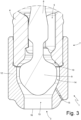
- the shutter 9 is separate from the valve seat 10 creating a passage opening having a crown-shaped section; consequently, the hydrogen which is injected through the injection nozzle 3 has at the outlet an internally hollow conical shape.
- the electromagnetic actuator 6 is configured to move the shutter 9 between the closed position of the injection valve 7, in which the shutter 9 is pressed against the valve seat 10, and the open position (illustrated in Figure 2 ) of the injection valve 7, in which the shutter 9 is separate from the valve seat 10 for creating the annular opening through which the hydrogen flows.
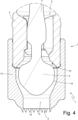
- a tubular sleeve 12 is arranged which entirely contains the shutter 9 therein, and ends with the injection nozzle 3; namely, the injection nozzle 3 is delimited by the sleeve 12, which constitutes the final element of the fuel (fuel) injector 1.
- the shutter 9 has, in the embodiment illustrated in Figures 2-5 , a bulb-like shape and has an outer surface comprising a first portion which faces the valve seat 10 and is shaped so as to be sealingly coupled to an inner surface of the valve seat 10 when the injection valve 7 is in the closed position, and a second portion which faces an inner surface of the sleeve 12 and always remains at a given distance from the inner surface of the sleeve 12.
- annular injection duct 14 is delimited, the initial part of which is created when the injection valve 7 is in the open position and along which the fuel flows towards the end zone 13 of the injection duct 14 (namely, towards the injection nozzle 3) when the injection valve 7 is in the open position (illustrated in Figure 2 ). More generally, the injection duct 14 is externally delimited (defined) by the inner surface of the valve seat 10 and subsequently by the inner surface of the sleeve 14.
- the injection duct 14 which is created (initially between the shutter 9 and the valve seat 10 and the sleeve 12) when the injection valve 7 is in the open position (illustrated in Figure 2 ) has a (an everywhere) converging initial segment, in which an area of the injection duct 14 progressively decreases from a first maximum value at the beginning of the injection duct 14 to a minimum value (which is located at the center of the injection duct 14 downstream of the valve seat 10 and corresponds to the throat section) and a (at least initially) diverging final segment in which the area of the injection duct 14 progressively increases from the minimum value until reaching a second maximum value at the end of the injection duct 14 (generally, the second maximum value is greater than the first maximum value).
- the injection duct 14 has an intermediate segment which is interposed between the (everywhere) converging initial segment and the (at least initially) diverging final segment, has a constant area equal to the minimum value, and has a non-zero axial length.
- the converging initial segment of the injection duct 14 extends from the zone in which the area of the injection duct 14 is equal to the first maximum value to the zone in which the area of the injection duct 14 is equal to the minimum value (namely, the throat section) and thus the intermediate segment begins; whereas, the diverging final segment of injection duct 14 extends from the zone in which the area of the injection duct 14 is equal to the minimum value (namely, the throat section) and thus the intermediate segment ends at least to the zone in which the area of the injection duct 14 is equal to the second maximum value.
- the (at least initially) diverging final segment of the injection duct 14 is axially longer than the (everywhere) converging initial segment of the injection duct 14 (namely, the hydrogen must travel a greater length for passing through the diverging final segment of the injection duct 14 than the converging initial segment).
- the convergence-divergence alternation in the injection duct 14 constitutes a de Laval nozzle, which is a supersonic exhaust nozzle and is made up of a tube having a central bottleneck, similar to an asymmetric hourglass; its steady-state operation (in which the speed of the hydrogen is equal to the speed of the sound in the throat section, namely, in the smaller section) allows accelerating the hydrogen to supersonic speeds, conveying the exhaust flow so as to transform its thermal and pressure energy into kinetic energy.
- the shutter 9 has: an initial portion which is coupled to the valve seat 10 and has, along the longitudinal axis 2, a progressively increasing outer diameter, an intermediate portion having, along the longitudinal axis 2, a constant outer diameter, and an end portion which is closer to injection nozzle 3 and has, along the longitudinal axis 2, a progressively decreasing outer diameter.
- the sleeve 12 has: an initial portion which is arranged immediately downstream of the valve seat 10, is located at the intermediate portion of the shutter 9, and has, along the longitudinal axis 2, a constant inner diameter, an intermediate portion having, along the longitudinal axis 2, a decreasing inner diameter, and an end portion which is closer to the injection nozzle 3, delimits the end zone 13 of the injection duct 14, and has along the longitudinal axis 2 a constant inner diameter.
- the area of the injection duct 14 progressively increases from the minimum value until reaching the second maximum value, which is preferably reached at the end of the injection duct 14 (namely, the second maximum value can be reached at the end of the injection duct 14 at the injection nozzle 3 or it can be reached before the end of the injection duct 14 upstream of the injection nozzle 3).
- the shutter 9 substantially only has the initial portion which is coupled to the valve seat 10 and has, along the longitudinal axis 2, a progressively increasing outer diameter and the intermediate portion having, along the longitudinal axis 2, a constant outer diameter; namely, in the embodiment illustrated in Figure 6 , the end portion which is closer to the injection nozzle 3 and which has, along the longitudinal axis 2, a progressively decreasing outer diameter, is substantially absent.
- the shutter 9 ends with a truncated shape and thus has a lower wall which is closer to the injection nozzle 3 and is flat.
- the area of the injection duct 14 increases stepwise from the minimum value to the second maximum value at the flat lower wall of the shutter 9.
- the end zone 13 of the injection duct 14 is coaxial to the longitudinal axis 2 of the fuel (or other gaseous fuel) injector 1, and thus gives the hydrogen spray exiting the injection nozzle 3 an orientation coaxial to the longitudinal axis 2 of the fuel injector 1.
- the end zone 13 of the injection duct 14 is tilted (angled) relative to the longitudinal axis 2 of the fuel injector 1 (namely, the end zone 13 of the injection duct 14 forms an acute angle with the longitudinal axis 2 of the fuel injector 1) and thus gives the fuel spray exiting the injection nozzle 3 a tilted (angled) orientation relative to the longitudinal axis 2 of the fuel injector 1.
- the sleeve 12 comprises at least one lateral through-duct 15 which goes through the sleeve 12 from side to side and leads into the end zone 13 of the injection duct 14; namely, the lateral duct 15 puts the combustion chamber of a corresponding cylinder (surrounding the final part of the fuel injector 1) in communication with the end zone 13 of the injection duct 14.
- each lateral duct 15 is tilted relative to the longitudinal axis 2 of the fuel injector 1 and forms an acute angle with the longitudinal axis 2 of the fuel injector 1; in particular, the acute angle between each lateral duct 15 and the longitudinal axis 2 of the fuel injector 1 ranges from 20° to 40° and is preferably 30°.
- the sleeve 12 comprises a plurality of lateral ducts 15 which can be arranged along the entire circular extension of the sleeve 12 (namely, they can form a closed circle and thus have a symmetrical distribution around the longitudinal axis 2) or can be arranged only along a limited portion of the circular extension of the sleeve 12 (namely, they can form a circumferential arc and thus have an asymmetrical distribution around the longitudinal axis 2) .
- the function of the lateral ducts 15 is to allow the suction of air (namely, of comburent) from the combustion chamber of a corresponding cylinder (surrounding the final part of the fuel injector 1) to the end zone 13 of the injection duct 14 in order to allow already on the inside of the end zone 13 of the injection duct 14 a first mixing between the hydrogen (the fuel) and the air (the comburent), and thus improving the overall mixing between the hydrogen and the air.
- the presence of the lateral ducts 15 allows improving the overall mixing between the hydrogen (the fuel) and the air (the comburent) present in the combustion chamber of a corresponding cylinder (surrounding the final part of the fuel injector 1).
- the injection duct 14 has an initially converging and subsequently diverging shape (for constituting a de Laval nozzle and thus determines an increase in the speed of the fuel and a decrease in the pressure of the fuel, consequently creating in the end zone 13 of the injection duct 14 a (relative) depression which sucks air from the combustion chamber of a corresponding cylinder (surrounding the final part of the fuel injector 1) through the lateral ducts 15.
- the lateral ducts 15 are symmetrically distributed around the longitudinal axis 2 of the fuel (fuel) injector 1, their presence does not affect the direction of the fuel spray coming out of the injection nozzle 3; whereas, if the lateral ducts 15 are asymmetrically distributed around the longitudinal axis 2 of the fuel injector 1 (i.e. on one side of the sleeve 12 there are more lateral ducts 15 or there are larger lateral ducts 15 than on the opposite side of the sleeve 12), their presence affects the direction of the fuel spray coming out of the injection nozzle 3 and which can thus assume a tilted (angled) direction relative to the longitudinal axis 2 of the fuel (fuel) injector 1.
- a non-symmetrical distribution of the lateral ducts 15 relative to the longitudinal axis 2 of the fuel (fuel) injector 1 allows giving the fuel spray coming out of the injection nozzle 3 a tilt relative to the longitudinal axis 2 of fuel (fuel) injector 1.
- an outer edge 16 of the injection nozzle 3 is smooth.
- the outer edge 16 of the injection nozzle 3 is indented (i.e. has a more or less irregular series of projections and recesses).
- the outer edge 16 of the injection nozzle 3 has a series of lobes (which can be more rounded or more pointed) which give the outer edge 16 a sawtooth shape.
- the indented (uneven, irregular) shape of the outer edge 16 of the injection nozzle 3 allows improving the mixing of the fuel with the air (comburent) as it generates greater turbulences in the fuel spray.
- the indented (uneven, irregular) shape of the outer edge 16 of the injection nozzle 3 allows reducing the noise (namely, pressure waves in the audible range) which is generated during the fuel spray: the indented shape increases the mixing process and this weakens the formation of large-scale structures (associated with the generation of low-frequency noise falling within the audible range) and excites smaller-scale structures (associated with the generation of high-frequency noise which is outside the audible range).
- the end zone 13 of the injection duct 14 communicates towards the outside (namely, towards the combustion chamber) to inject the fuel by means of one single opening; namely, in the embodiment illustrated in Figures 2 , 3 , and 4 , the injection nozzle 3 has one single opening for the injection of the fuel.
- the end zone 13 of the injection nozzle 14 communicates towards the outside (namely, towards the combustion chamber) to inject the fuel by means of a series of openings 17 which are side by side and may have differentiated sizes (diameters); namely, in the embodiment illustrated in Figure 5 , the injection nozzle 3 has a series of openings 17 which are side by side and may have differentiated sizes (diameters).
- a "multihole" configuration is provided in which the fuel exits the end zone 13 of the injection duct 14 through a series of openings 17 which are side by side and of different sizes (diameters) which constitute the injection nozzle 3.
- the openings 17 are parallel to one another, but alternatively they could be tilted (not parallel) with respect to one another.
- the fuel injector 1 can be utilized to inject any other type of gaseous fuel such as, for example, methane.
- the fuel injector 1 described above has numerous advantages.
- the fuel injector 1 described above generates a fuel spray which allows optimizing the mixing between the air (the comburent) and the hydrogen (the fuel).
- the fuel injector 1 described above imparts on the hydrogen (fuel) spray a high outlet speed, which facilitates the mixing with the air increasing the swirling motions.
- the fuel injector 1 described above allows directing the hydrogen (fuel) spray with a certain angle relative to the longitudinal axis 2 of the fuel injector 1, enabling imparting on the fuel spray the optimum direction regardless of the position and orientation of the fuel (fuel) injector 1 in the cylinder crown (tendentially, the fuel spray has to invest the piston laterally and not in the center in order to maximize the turbulences and thus to have a better mixing of the fuel with the air).
- the fuel injector 1 described above results to be simple and inexpensive to produce since it has few constructive differences which are easy to manufacture compared to a similar known hydrogen (fuel) injector.
Landscapes
- Engineering & Computer Science (AREA)
- Chemical & Material Sciences (AREA)
- Combustion & Propulsion (AREA)
- Mechanical Engineering (AREA)
- General Engineering & Computer Science (AREA)
- Chemical Kinetics & Catalysis (AREA)
- General Chemical & Material Sciences (AREA)
- Oil, Petroleum & Natural Gas (AREA)
- Analytical Chemistry (AREA)
- Fuel-Injection Apparatus (AREA)
Applications Claiming Priority (1)
| Application Number | Priority Date | Filing Date | Title |
|---|---|---|---|
| IT102023000019236A IT202300019236A1 (it) | 2023-09-19 | 2023-09-19 | Iniettore di carburante per un carburante gassoso |
Publications (2)
| Publication Number | Publication Date |
|---|---|
| EP4530461A1 true EP4530461A1 (de) | 2025-04-02 |
| EP4530461B1 EP4530461B1 (de) | 2026-01-28 |
Family
ID=88839282
Family Applications (1)
| Application Number | Title | Priority Date | Filing Date |
|---|---|---|---|
| EP24201038.7A Active EP4530461B1 (de) | 2023-09-19 | 2024-09-18 | Kraftstoffinjektor für gasförmigen kraftstoff |
Country Status (5)
| Country | Link |
|---|---|
| US (1) | US20260078722A1 (de) |
| EP (1) | EP4530461B1 (de) |
| JP (1) | JP2025044165A (de) |
| CN (1) | CN119664537A (de) |
| IT (1) | IT202300019236A1 (de) |
Citations (3)
| Publication number | Priority date | Publication date | Assignee | Title |
|---|---|---|---|---|
| US20010025892A1 (en) | 1999-12-03 | 2001-10-04 | Mccoy James J. | Supersonic injector for gas engine |
| WO2007087685A1 (en) * | 2006-02-02 | 2007-08-09 | Orbital Australia Pty Ltd | A gaseous fuel injection system |
| DE202023100690U1 (de) | 2022-02-16 | 2023-04-04 | Marelli Europe S.P.A. | Einspritzventil für gasförmigen Kraftstoff, insbesondere Wasserstoff, für eine Brennkraftmaschine und Brennkraftmaschine, die mit diesem Einspritzventil ausgestattet ist |
-
2023
- 2023-09-19 IT IT102023000019236A patent/IT202300019236A1/it unknown
-
2024
- 2024-09-16 US US18/886,589 patent/US20260078722A1/en active Pending
- 2024-09-18 EP EP24201038.7A patent/EP4530461B1/de active Active
- 2024-09-18 CN CN202411300661.6A patent/CN119664537A/zh active Pending
- 2024-09-18 JP JP2024160718A patent/JP2025044165A/ja active Pending
Patent Citations (3)
| Publication number | Priority date | Publication date | Assignee | Title |
|---|---|---|---|---|
| US20010025892A1 (en) | 1999-12-03 | 2001-10-04 | Mccoy James J. | Supersonic injector for gas engine |
| WO2007087685A1 (en) * | 2006-02-02 | 2007-08-09 | Orbital Australia Pty Ltd | A gaseous fuel injection system |
| DE202023100690U1 (de) | 2022-02-16 | 2023-04-04 | Marelli Europe S.P.A. | Einspritzventil für gasförmigen Kraftstoff, insbesondere Wasserstoff, für eine Brennkraftmaschine und Brennkraftmaschine, die mit diesem Einspritzventil ausgestattet ist |
Also Published As
| Publication number | Publication date |
|---|---|
| EP4530461B1 (de) | 2026-01-28 |
| CN119664537A (zh) | 2025-03-21 |
| IT202300019236A1 (it) | 2025-03-19 |
| US20260078722A1 (en) | 2026-03-19 |
| JP2025044165A (ja) | 2025-04-01 |
Similar Documents
| Publication | Publication Date | Title |
|---|---|---|
| US6644565B2 (en) | Fuel injection nozzle for self-igniting internal combustion engines | |
| JPH03182682A (ja) | 燃料噴射弁 | |
| KR100287309B1 (ko) | 내연기관용연료분사노즐 | |
| CN109579052B (zh) | 一种火焰稳定器 | |
| CN219605427U (zh) | 用于内燃机的气体燃料喷射器和氢动力内燃机 | |
| US7104475B2 (en) | Low pressure fuel injector nozzle | |
| US11187199B2 (en) | Spray orifice disk and valve | |
| US7185831B2 (en) | Low pressure fuel injector nozzle | |
| US7438241B2 (en) | Low pressure fuel injector nozzle | |
| EP4530461B1 (de) | Kraftstoffinjektor für gasförmigen kraftstoff | |
| US20060231065A1 (en) | Fuel injector for an internal combustion engine | |
| JPH06317234A (ja) | 内燃機関用の燃料噴射ノズル | |
| CN113503565B (zh) | 一种用于微型涡轮发动机的收扩式环形蒸发管 | |
| US20200025060A1 (en) | Fuel Injector and Nozzle Passages Therefor | |
| CN100494668C (zh) | 一种燃油喷射器以及一种包含这种喷射器的发动机 | |
| US5607109A (en) | Fuel injection nozzle and method of making | |
| RU97121007A (ru) | Форсунка с двухпоточным тангенциальным входом | |
| BR102024019205A2 (pt) | Injetor de combustível para um combustível gasoso | |
| US6918549B2 (en) | Fuel injector tip for control of fuel delivery | |
| CN101466945A (zh) | 燃料喷射系统以及改善喷雾形成的燃料喷射器 | |
| CN113250793A (zh) | 废气后处理系统和方法 | |
| US20230235717A1 (en) | Fuel injector and nozzle assembly having spray duct with center body for increased flame liftoff length | |
| JP2593105B2 (ja) | 燃料噴射装置 | |
| JP2593102B2 (ja) | 燃料噴射装置 | |
| RU49115U1 (ru) | Насадка инжекторная к глушителю двигателя внутреннего сгорания |
Legal Events
| Date | Code | Title | Description |
|---|---|---|---|
| PUAI | Public reference made under article 153(3) epc to a published international application that has entered the european phase |
Free format text: ORIGINAL CODE: 0009012 |
|
| STAA | Information on the status of an ep patent application or granted ep patent |
Free format text: STATUS: THE APPLICATION HAS BEEN PUBLISHED |
|
| STAA | Information on the status of an ep patent application or granted ep patent |
Free format text: STATUS: REQUEST FOR EXAMINATION WAS MADE |
|
| AK | Designated contracting states |
Kind code of ref document: A1 Designated state(s): AL AT BE BG CH CY CZ DE DK EE ES FI FR GB GR HR HU IE IS IT LI LT LU LV MC ME MK MT NL NO PL PT RO RS SE SI SK SM TR |
|
| 17P | Request for examination filed |
Effective date: 20250318 |
|
| RIC1 | Information provided on ipc code assigned before grant |
Ipc: F02M 21/02 20060101AFI20250819BHEP |
|
| GRAP | Despatch of communication of intention to grant a patent |
Free format text: ORIGINAL CODE: EPIDOSNIGR1 |
|
| STAA | Information on the status of an ep patent application or granted ep patent |
Free format text: STATUS: GRANT OF PATENT IS INTENDED |
|
| INTG | Intention to grant announced |
Effective date: 20250930 |
|
| GRAS | Grant fee paid |
Free format text: ORIGINAL CODE: EPIDOSNIGR3 |
|
| GRAA | (expected) grant |
Free format text: ORIGINAL CODE: 0009210 |
|
| STAA | Information on the status of an ep patent application or granted ep patent |
Free format text: STATUS: THE PATENT HAS BEEN GRANTED |
|
| P01 | Opt-out of the competence of the unified patent court (upc) registered |
Free format text: CASE NUMBER: UPC_APP_0015986_4530461/2025 Effective date: 20251205 |
|
| AK | Designated contracting states |
Kind code of ref document: B1 Designated state(s): AL AT BE BG CH CY CZ DE DK EE ES FI FR GB GR HR HU IE IS IT LI LT LU LV MC ME MK MT NL NO PL PT RO RS SE SI SK SM TR |
|
| REG | Reference to a national code |
Ref country code: CH Ref legal event code: F10 Free format text: ST27 STATUS EVENT CODE: U-0-0-F10-F00 (AS PROVIDED BY THE NATIONAL OFFICE) Effective date: 20260128 Ref country code: GB Ref legal event code: FG4D |
|
| REG | Reference to a national code |
Ref country code: DE Ref legal event code: R096 Ref document number: 602024002305 Country of ref document: DE |
|
| REG | Reference to a national code |
Ref country code: IE Ref legal event code: FG4D |