EP4530429A1 - System zum automatischen auf- und abrollen eines rollbaren rollos - Google Patents
System zum automatischen auf- und abrollen eines rollbaren rollos Download PDFInfo
- Publication number
- EP4530429A1 EP4530429A1 EP24201843.0A EP24201843A EP4530429A1 EP 4530429 A1 EP4530429 A1 EP 4530429A1 EP 24201843 A EP24201843 A EP 24201843A EP 4530429 A1 EP4530429 A1 EP 4530429A1
- Authority
- EP
- European Patent Office
- Prior art keywords
- magnetic field
- rollable screen
- coil
- screen
- rollable
- Prior art date
- Legal status (The legal status is an assumption and is not a legal conclusion. Google has not performed a legal analysis and makes no representation as to the accuracy of the status listed.)
- Pending
Links
Images



Classifications
-
- E—FIXED CONSTRUCTIONS
- E06—DOORS, WINDOWS, SHUTTERS, OR ROLLER BLINDS IN GENERAL; LADDERS
- E06B—FIXED OR MOVABLE CLOSURES FOR OPENINGS IN BUILDINGS, VEHICLES, FENCES OR LIKE ENCLOSURES IN GENERAL, e.g. DOORS, WINDOWS, BLINDS, GATES
- E06B9/00—Screening or protective devices for wall or similar openings, with or without operating or securing mechanisms; Closures of similar construction
- E06B9/02—Shutters, movable grilles, or other safety closing devices, e.g. against burglary
- E06B9/08—Roll-type closures
- E06B9/11—Roller shutters
- E06B9/13—Roller shutters with closing members of one piece, e.g. of corrugated sheet metal
-
- E—FIXED CONSTRUCTIONS
- E06—DOORS, WINDOWS, SHUTTERS, OR ROLLER BLINDS IN GENERAL; LADDERS
- E06B—FIXED OR MOVABLE CLOSURES FOR OPENINGS IN BUILDINGS, VEHICLES, FENCES OR LIKE ENCLOSURES IN GENERAL, e.g. DOORS, WINDOWS, BLINDS, GATES
- E06B9/00—Screening or protective devices for wall or similar openings, with or without operating or securing mechanisms; Closures of similar construction
- E06B9/56—Operating, guiding or securing devices or arrangements for roll-type closures; Spring drums; Tape drums; Counterweighting arrangements therefor
- E06B9/68—Operating devices or mechanisms, e.g. with electric drive
-
- E—FIXED CONSTRUCTIONS
- E06—DOORS, WINDOWS, SHUTTERS, OR ROLLER BLINDS IN GENERAL; LADDERS
- E06B—FIXED OR MOVABLE CLOSURES FOR OPENINGS IN BUILDINGS, VEHICLES, FENCES OR LIKE ENCLOSURES IN GENERAL, e.g. DOORS, WINDOWS, BLINDS, GATES
- E06B9/00—Screening or protective devices for wall or similar openings, with or without operating or securing mechanisms; Closures of similar construction
- E06B9/56—Operating, guiding or securing devices or arrangements for roll-type closures; Spring drums; Tape drums; Counterweighting arrangements therefor
- E06B9/68—Operating devices or mechanisms, e.g. with electric drive
- E06B2009/6809—Control
- E06B2009/6818—Control using sensors
Definitions
- This invention generally relates to rollable screens, such as sun protection screens. More specifically, the present invention relates to automating the rolling up and unrolling of these rollable screens.
- a system for automatically rolling up the rollable screen can comprise a motor for rotating a rotatable tube for rolling up and unrolling the rollable screen, and a controller for controlling the motor.
- the controller it is advantageous for the controller to have information about the position of the screen, for example whether it is rolled up or unrolled.
- the motor can be turned off at the right time, for example when the screen is completely rolled up or unrolled, or when the screen has reached a certain desired position.
- WO2019175573 and US2021071476 describe magnets that can be attached to the screen, for example on an underside of the screen.
- a sensor such as a Hall sensor, can detect the magnets and thus determine the position of the unrollable screen.
- EP2835490 and WO2014066158 also describe the use of magnets attached to the fabric. Because magnets are typically quite thick and can form protrusions on the fabric, such a system with magnets attached to the fabric is less suitable for flexible screens, such as rollable screens formed from a sunshade textile.
- the present invention provides a system for automatically rolling up and unrolling a rollable screen.
- the system comprises the rollable screen, comprising a magnetic field deforming structure.
- the system further comprises a rotatable tube for rolling up and unrolling the rollable screen, and a motor for rotating the tube.
- the system further comprises at least one coil assembly for generating a magnetic field and for detecting the generated magnetic field, arranged adjacent to a path along which the magnetic field deforming structure travels when the rollable screen is being rolled up and unrolled such that the magnetic field detected by the coil assembly is dependent on the rolled-up and unrolled position of the rollable screen.
- the system further comprises a controller suitable for controlling the motor based on the magnetic field detected by the coil assembly.
- each coil assembly comprises a transmitter coil for generating the magnetic field and a receiver coil for detecting the generated magnetic field, wherein the transmitter coil and the receiver coil are arranged on opposite sides of the path. It is an advantage of these embodiments that the automation of the rolling up and unrolling of a rollable screen can be relatively simple.
- each coil assembly comprises a coil suitable for detecting the magnetic field generated by the coil itself. It is an advantage of these embodiments that only a single coil is required, which can make production of the system inexpensive and efficient.
- the magnetic field deforming structure in a direction of rolling up or unrolling the rollable screen, comprises magnetic field deforming elements spaced at substantially equal distances from each other and separated from each other by areas substantially transparent to the magnetic field. It is an advantage of these embodiments that simple determination of the position, direction and speed of the rolling up and unrolling of the rollable screen can be achieved. Thus, moreover, it can be easily determined whether the rolling up or unrolling of the screen is blocked by an obstacle.
- the invention is, however, not limited to these embodiments, and alternatively it is possible for the magnetic field deforming elements not to be spaced at equal distances.
- the magnetic field deforming structure has the shape of a comb.
- the magnetic field deforming elements are connected to each other (forming teeth of the comb fastened to a back of the comb), which allows them to be easily spaced at substantially equal distances from each other.
- the back of the comb can be used to detect whether the beginning or end of the rollable screen has been reached, for example by providing a second coil assembly adjacent to a path along which the back of the comb travels when the rollable screen is being rolled up and unrolled.
- the magnetic field deforming structure can, for example, variably deform the magnetic field along the path along which the magnetic field deforming structure travels when the rollable screen is being rolled up and unrolled.
- a thickness of the magnetic field deforming structure varies along the path.
- different materials, with different efficiency in deforming, e.g. blocking or reflecting a magnetic field are arranged along the path.
- a width of the magnetic field deforming structure is varied along the path.
- the magnetic field deforming structure comprises a film, a wire, an electrically conductive ink, a magnetic field blocking material such as graphite, a zip or a magnetically conductive material. It is an advantage of these embodiments that these structures can be easily attached to the screen.
- the electrically conductive ink can be printed on the rollable screen, wherein the printed ink adheres to the screen. Electrically conductive or magnetic field blocking wire can be used to sew or stitch a pattern.
- the magnetic field deforming structure has a thickness from 5 to 200 ⁇ m. It is an advantage of these embodiments that the magnetic field deforming structure can have a limited influence on the thickness of the rollable screen, and can also be rolled up on the rotatable tube.
- the system comprises at least one side guide for receiving a side of the rollable screen so as to guide the rollable screen, wherein the magnetic field deforming structure is arranged on the side of the rollable screen, and wherein the at least one coil assembly is arranged in the side guide. It is an advantage of these embodiments that the magnetic field deforming structure and the coil assembly can be shielded from external influences, such as weather, flying materials, for example in case of wind, or touch.
- the rollable screen contains a fabric, such as a sunshade textile, provided on at least one side with a zip for holding the fabric in the side guide, and wherein the magnetic field deforming structure is arranged between the fabric and the zip.
- the zip typically comprises a zip textile, such as a strip of fabric or another material, fastened to the fabric, for example by stitching or welding such as ultrasonic welding or high-frequency welding, and zip teeth fastened to the zip textile, wherein the zip teeth are connected to the fabric via the zip textile.
- the magnetic field deforming structure is arranged between the fabric and the zip textile of the zip. It is an advantage of these embodiments that the magnetic field deforming structure, e.g. film or wire, is well protected from possible damage by touch and when being rolled up on the tube.
- the magnetic field deforming structure comprises a metal, preferably aluminium, copper or stainless steel. It is an advantage of these embodiments that the magnetic field deforming structure can be thin and still achieve good deformation, for example blocking, of the magnetic field.
- the system is suitable for turning off the motor when the magnetic field detected by the coil assembly is substantially constant for a predetermined period of time. It is an advantage of these embodiments that it can be easily determined whether the screen is fully rolled up or fully unrolled, or blocked by an obstacle.
- the rollable screen is typically used to block light that would enter through a window in the absence of the rollable screen, and is typically, when unrolled, parallel relative to the window.
- the rollable screen comprises a fabric, preferably a sunshade textile.
- the present invention is in particular suitable for sunshade textiles, such as screens, which are typically thin and flexible. It is a major advantage for the sunshade textile that the magnetic field deforming structure can also be thin and flexible.
- the present invention provides a system for automatically rolling up and unrolling a rollable screen.
- the system comprises the rollable screen, comprising a magnetic field deforming structure.
- the system further comprises a rotatable tube for rolling up and unrolling the rollable screen, and a motor for rotating the tube.
- the system further comprises at least one coil assembly for generating a magnetic field and for detecting the generated magnetic field, arranged adjacent to a path along which the magnetic field deforming structure travels when the rollable screen is being rolled up and unrolled such that the magnetic field detected by the coil assembly is dependent on the rolled-up and unrolled position of the rollable screen.
- the system further comprises a controller suitable for controlling the motor based on the magnetic field detected by the coil assembly.
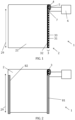
- FIG. 1 is a schematic depiction of an example of a system 1 for automatically rolling up and unrolling a rollable screen 2, according to embodiments of the present invention.
- the system 1 further comprises a rotatable tube 4 on which the rollable screen 2 can be rolled up, and from which it can be unrolled.
- Arrow 29 shows the direction along which the rollable screen 2 rolls up and unrolls.
- the tube 4 is coupled to a motor 5, in this example a tube motor 5 that is located in a cavity in the tube 4 and thus can drive the tube in rotation, although the present invention is not limited thereto.
- the motor 5 is communicatively connected to a controller 6, which can be used to control the motor 5.
- the rollable screen 2 comprises a magnetic field deforming structure 3, wherein the magnetic field deforming structure 3 is arranged on the side of the rollable screen 2.
- the magnetic field deforming structure 3 is fastened to a fabric or textile, such as the sunshade textile 21, of the rollable screen 2.
- the magnetic field deforming structure 3 has the shape of a comb, comprising a plurality of teeth 31 and a back 32 to which the teeth 31 are connected.
- the teeth 31 form, in a direction of rolling up or unrolling the rollable screen 2, magnetic field deforming elements spaced at substantially equal distances from each other and separated from each other by areas 33 substantially transparent to magnetic fields.
- the areas 33 that are substantially transparent to magnetic fields do not contain magnetic field deforming material.
- the fabric or textile, such as the sunshade textile 21, of the rollable screen 2 is substantially transparent to the magnetic field.
- the system 1 further comprises a coil assembly 7 arranged adjacent to a path along which the magnetic field deforming structure 3 travels when the rollable screen is being rolled up and unrolled.
- the coil assembly is located along the path that the magnetic field deforming structure 3 travels when the rollable screen 2 is being rolled up and unrolled.
- at least one coil assembly 7 is preferably arranged at the rotatable tube 4, such that the position of the rollable screen 2 can be determined even if the rollable screen 2 is substantially fully rolled up on the rotatable tube 4.
- the coil assembly 7 is arranged adjacent to a path along which the teeth 31, or the magnetic field deforming elements spaced at substantially equal distances from each other, travel.
- the coil assembly 7 is suitable for generating a magnetic field and for detecting the generated magnetic field.
- the magnetic field deforming structure 3 deforms the magnetic field generated by the coil assembly 7, such that the magnetic field detected by the coil assembly 7 is a dependent on the rolled-up and unrolled position of the rollable screen 2.
- the magnetic field deforming structure 3 can comprise, for example, a magnetic field blocking material, or a magnetic field absorbing material.
- the magnetic field detected by the coil assembly 7 can be weaker if one of the teeth 31 is located at the coil assembly 7, than if one of the areas 33 substantially transparent to magnetic fields is located at the coil assembly 7. In this way, the magnetic field detected by the coil assembly 7 will become weaker (when a tooth 31 passes) and stronger (when a substantially transparent area 33 passes) during the rolling up or unrolling of the rollable screen.
- the controller 6 can detect how often the detected magnetic field becomes alternately strong and weak, and on the basis thereof, in combination with information, for example from the motor 5, about the rotation direction of the motor 5 - that is, whether the motor 5 is rolling up or unrolling the rollable screen 2 -, and typically in combination with the known distance between consecutive teeth 31, determine the position of the rollable screen 2.
- the controller 6 can be suitable for determining, based on how often the detected magnetic field strengthens and weakens within a certain time period, the speed at which the rollable screen 2 is rolled up or unrolled.
- the teeth 31 are magnetic field deforming elements spaced at substantially equal distances from each other.
- the magnetic field deforming elements could be spaced at unequal distances from each other: the distance between successive magnetic field deforming elements could in this case, for example, increase as the distance from one end of the rollable screen 2 increases.
- a direction of movement (rolling up or unrolling of the rollable screen 2) could also be determined.
- FIG. 2 shows a similar system 1 to FIG. 1 , wherein the system 1 further comprises a first side guide 81 for receiving the side of the rollable screen 2 comprising the magnetic field deforming structure 3.
- the magnetic field deforming structure 3 is thereby protected by the side guide 81 from external influences, such as rain or flying materials.
- the coil assembly is also provided in the side guide 81 (and is therefore not shown in FIG. 2 ).
- the system comprises, in this example, a second side guide 82 for receiving an opposite side of the rollable screen 2, lying opposite the side of the rollable screen 2 comprising the magnetic field deforming structure 3.
- FIG. 3 shows a similar system 1 to FIG. 1 , wherein, in addition to the coil assembly 7 arranged adjacent to the path along which the teeth 31 move during the rolling up and unrolling of the rollable screen 2, the system comprises a further coil assembly 70 arranged adjacent to a path along which the back 32 moves during the rolling up and unrolling of the rollable screen 2 and which is also communicatively coupled to the controller 6.
- the further coil assembly 70 is also provided for generating a magnetic field and for detecting the magnetic field generated by the further coil assembly 70.
- this further coil assembly 70 is arranged at an end, away from the rotatable tube 4, of the path along which the back 32 moves, such that this further coil assembly 70 can detect whether an end of the back 32 has been reached, and hence whether an end of the rollable screen 2 has been reached.
- This further coil assembly 70 can, for example, serve to further regulate the position as determined by the coil assembly 7, or to calibrate the position as determined by the coil assembly 7.
- FIG. 4 shows a side view of a system 1 for automatically rolling up and unrolling a rollable screen 2.
- the coil assembly comprises a transmitter coil 71 for generating the magnetic field and a receiver coil 72 for detecting the generated magnetic field, wherein the transmitter coil 71 and the receiver coil 72 are arranged on either side (for example, front and back) of the path along which the magnetic field deforming structure moves when the rollable screen is being rolled up and unrolled.
- the transmitter coil 71 and the receiver coil 72 are controlled by the controller 6.
- the magnetic field deforming structure in a direction of rolling up or unrolling the rollable screen, comprises magnetic field deforming elements 31 spaced at substantially equal distances from each other and separated from each other by areas 33 substantially transparent to the magnetic field.
- the magnetic field deforming structure can comprise, or the magnetic field deforming elements 31 can comprise, a material that blocks, absorbs or reflects the generated magnetic field, such that, if one of the magnetic field deforming elements 31 is located between the transmitter coil 71 and the receiver coil 72, the receiver coil 72 can detect the magnetic field generated by the transmitter coil 71 only weakly, or not at all. If, on the other hand, one of the areas 33 that are substantially transparent to the magnetic field is located between the transmitter coil 71 and the receiver coil 72, the receiver coil 72 detects the magnetic field generated by the transmitter coil 71, which in this case is not weakened or is weakened only slightly.
- FIG. 5 shows a side view of another example of a system 1 for automatically rolling up and unrolling a rollable screen 2.
- the coil assembly can comprise a single coil 73 which can generate a magnetic field, and is suitable for detecting the magnetic field generated by the coil 73 itself.
- the magnetic field deforming structure 3 can, for example, be magnetically reflective.
- the magnetic field generated by the coil 73 can be reflected by a magnetic field deforming element 31 of the magnetic field deforming structure 3 located near the coil 73, wherein the magnetic field detected by the coil 73 can be strengthened by the magnetic field deforming element 31.
- a substantially transparent area 33 does not display that reflection of the generated magnetic field, such that the magnetic field measured by the coil 73 is not strengthened by reflection if the coil 73 is located next to the substantially transparent area 33.
- FIG. 6 shows another example of a system 1 according to embodiments of the present invention, wherein the system 1 comprises a plurality of coil assemblies: more specifically, in this example, four coil assemblies are shown.
- the coil assemblies are spaced at regular distances from each other adjacent to the path travelled by the magnetic field deforming structure 3 during the rolling up and unrolling of the rollable screen, but the present invention is not limited thereto.
- each of the four coil assemblies comprises a single coil 73 for generating a magnetic field and detecting the magnetic field generated by the single coil 73 itself, but the invention is not limited thereto, and coil assemblies with separate transmitter and receiver coils can also be implemented.
- Each of the plurality of coil assemblies for example each of the four coils 73, is connected to the controller 6.
- the use of multiple coil assemblies can provide a more accurate determination of the position, direction and speed.
- the use of multiple coil assemblies eliminates the need to rely on information from the motor, and consequently avoids, for example, the need to provide sensors for determining the rotation direction of the motor 5.
- the use of multiple coil assemblies makes it possible to detect that a rollable screen is being pushed up or pulled down when the motor is stationary.
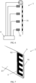
- FIG. 7 shows a rollable screen 2 according to embodiments of the present invention comprising a fabric 21, such as a sunshade textile 21, provided on at least one side with a zip 9 for holding the fabric 21 in a side guide.
- the zip 9 comprises zip teeth 91 that can be included in the side guide, and a zip textile 92, typically in the form of a strip of fabric, to which the zip teeth 91 are fastened, and which is fastened to the fabric 21, i.e., the sunshade textile 21.
- the zip 9 can be guideably fastened into a side guide (not shown in FIG. 7 , but for example as shown in FIG. 2 ).
- the side guide can comprise, for example, a groove for receiving the zip teeth 91, wherein the zip teeth 91 can slide up and down through the groove to move the rollable screen 2 up and down.
- the zip teeth 91 are formed from a magnetic field deforming material, and the zip 9, i.e., the zip teeth 91, thus comprise the magnetic field deforming structure.
- the zip teeth 91 can comprise magnetic field deforming elements spaced at substantially equal distances from each other - that is, each of the zip teeth 91 forms a magnetic field deforming element - separated from each other by areas substantially transparent to the magnetic field.
- the zip teeth 91 of the zip 9 can be located at irregular distances from each other. No other magnetic field deforming structure need be provided in these embodiments.
- the zip 9 can be fastened to the fabric 21 by means of magnetic field deforming stitching, or by means of a magnetic field deforming adhesive.
- the zip 9, in this example the zip textile 92 can be fastened to the fabric 21 by means of stitches.
- the zip textile 92 can be fastened to the fabric 21 by gluing, or welding, such as ultrasonic welding or high-frequency welding.
- a surface of the zip textile 92 and/or a surface of the fabric 21 can be melted (for example, by using ultrasonic or high-frequency mechanical vibrations), after which the surface of the zip textile 92 is contacted with the surface of the fabric 21.
- the melted surface then solidifies, which can result in a solid bond between the fabric 21 and the zip 9, e.g., the zip textile 92.
- the zip 9 can be fastened to the fabric 21 by means of magnetic field deforming stitching, or by means of a magnetic field deforming adhesive. No other magnetic field deforming structure need be provided in these embodiments. Preferably, welding or gluing is used, as these techniques for fastening the zip 9 to the fabric 21 can have a limited influence on the thickness of the rollable screen 2.
- the zip textile 92 is not necessary and, in specific embodiments, the zip teeth 91 are directly fastened to the fabric 21.
- the zip 9 comprises a zip textile 92.
- a magnetic field deforming structure 3 in the form of a comb, is arranged between the fabric 21 and the zip 9, more specifically between the fabric 21 and the zip textile 92.
- the magnetic field deforming structure 3, which can comprise, for example, a film with a thickness of 5 to 200 ⁇ m, can thus be pressed tightly between the fabric 21, i.e., the sunshade textile 21, and the zip textile 92, which can provide physical support to the magnetic field deforming structure 3.
- the zip textile 92 and the fabric 21 can thus provide protection to the magnetic field deforming structure 3 from external influences, such as weather or physical contact, which could damage the magnetic field deforming structure 3 (in this example, a thin, typically delicate, film).
- FIG. 8 shows a vertical cross-sectional view of the rollable screen 2 of FIG. 7 , wherein the magnetic field deforming structure 3 is arranged between the zip textile of the zip 9 and the sunshade textile 21 of the rollable screen 2.
- Three coil assemblies 7 are arranged adjacent to the path along which the magnetic field deforming elements 31 of the magnetic field deforming structure 3 move when the rollable screen 2 is being rolled up and unrolled. (In the example shown, the rollable screen 2 moves up when rolling up, and down when unrolling). More specifically, a transmitter coil 71 for generating a magnetic field and a receiver coil 72 for detecting the generated magnetic field are arranged on either side of the rollable screen 2, in front of each of the three coil assemblies 7 (or included therein).
- the zip textile and the sunshade textile 21 are typically substantially transparent to the magnetic field. In this example, the entirety of the zip 9 (including the zip teeth) is substantially transparent to the magnetic field.
- the magnetic field deforming structure in the above examples is typically in the form of a comb, which, in a direction of rolling up or unrolling the rollable screen, comprises magnetic field deforming elements spaced at substantially equal distances from each other and separated from each other by areas substantially transparent to the magnetic field, and connected to a back of the comb, the invention is not limited thereto.
- FIG. 9 shows a magnetic field deforming structure 30 comprising, in a direction of rolling up or unrolling the rollable screen 2, magnetic field deforming elements 310 spaced at substantially equal distances from each other and separated from each other by areas 330 substantially transparent to the magnetic field, yet without these magnetic field deforming elements 310 being connected to each other by, for example, a magnetic field deforming back.
- FIG. 10 shows a magnetic field deforming structure 301 comprising, in a direction of rolling up or unrolling the rollable screen, magnetic field deforming elements 311 spaced at unequal distances from each other and separated from each other by areas 331 substantially transparent to the magnetic field.
- the magnetic field deforming elements 311 are not connected by, for example, a magnetic field deforming back, but the invention is not limited thereto. More specifically, the distance between successive magnetic field deforming elements 311 becomes smaller in a direction of unrolling the rollable screen 2. Alternatively, the distance between successive magnetic field deforming elements 311 could become larger in a direction of unrolling the rollable screen 2.
- the time between detection of successive magnetic field deforming elements 311 can easily be used to determine how far the rollable screen 201 has been rolled up or unrolled, for example, by a controller (not shown).
- FIG. 11 shows a magnetic field deforming structure 302 comprising, in a direction of rolling up or unrolling the rollable screen 2, magnetic field deforming elements 312 spaced at unequal distances from each other and separated from each other by areas 332 substantially transparent to the magnetic field.
- the magnetic field deforming elements 312 are not connected by, for example, a magnetic field deforming back, but the invention is not limited thereto. More specifically, the magnetic field deforming elements 312 are grouped 342, wherein different groups 332 contain a different number of magnetic field deforming elements 312.
- the number of magnetic field deforming elements 312 in successive groups 342 becomes smaller in a direction of unrolling the rollable screen 2, but the invention is not limited thereto and instead of becoming smaller, the number could become larger, or the number could be varying or arbitrary.
- the number of grouped 342 magnetic field deforming elements 312 can be used to derive how far the rollable screen 201 has been rolled up or unrolled, for example by a controller (not shown).
Landscapes
- Engineering & Computer Science (AREA)
- Structural Engineering (AREA)
- Architecture (AREA)
- Civil Engineering (AREA)
- Operating, Guiding And Securing Of Roll- Type Closing Members (AREA)
Applications Claiming Priority (1)
| Application Number | Priority Date | Filing Date | Title |
|---|---|---|---|
| BE20235794A BE1032010B1 (nl) | 2023-09-27 | 2023-09-27 | Systeem voor het automatisch oprollen en afrollen van een oprolbaar scherm |
Publications (1)
| Publication Number | Publication Date |
|---|---|
| EP4530429A1 true EP4530429A1 (de) | 2025-04-02 |
Family
ID=88206840
Family Applications (1)
| Application Number | Title | Priority Date | Filing Date |
|---|---|---|---|
| EP24201843.0A Pending EP4530429A1 (de) | 2023-09-27 | 2024-09-23 | System zum automatischen auf- und abrollen eines rollbaren rollos |
Country Status (2)
| Country | Link |
|---|---|
| EP (1) | EP4530429A1 (de) |
| BE (1) | BE1032010B1 (de) |
Citations (9)
| Publication number | Priority date | Publication date | Assignee | Title |
|---|---|---|---|---|
| US5540269A (en) * | 1993-04-05 | 1996-07-30 | Plumer (Societe Anonyme) | Motor-driven roller blind |
| EP1650625A1 (de) | 2004-10-25 | 2006-04-26 | Somfy SAS | Motorgetriebener Schirm und Verfahren zur seiner Betätigung |
| EP2441911A1 (de) | 2010-10-13 | 2012-04-18 | Ditec S.P.A. | Vorrichtung zur Detektion der Geschwindigkeit des Vorhangs einer schnellen Rolltür |
| WO2014066158A1 (en) | 2012-10-22 | 2014-05-01 | Rytec Corporation | Switch ladder sensor for roll-up door |
| EP2835490A2 (de) | 2013-08-08 | 2015-02-11 | Peter Charles Andre de la Porte | Tür für ein Industriegebäude |
| EP2848758A1 (de) | 2012-05-11 | 2015-03-18 | Amiserru, S.L. | Schnellöffnungstür |
| EP3105400A1 (de) | 2014-02-12 | 2016-12-21 | Assa Abloy Entrance Systems AB | Schnelle aufrolltür mit einem vorhanggeschwindigkeitsdetektor |
| WO2019175573A1 (en) | 2018-03-12 | 2019-09-19 | Ansa Door Systems Ltd | Safety device for a movable barrier system |
| US20210071476A1 (en) | 2019-09-09 | 2021-03-11 | Rite-Hite Holding Corporation, | Apparatus and methods for door curtain breakaway detection |
-
2023
- 2023-09-27 BE BE20235794A patent/BE1032010B1/nl active IP Right Grant
-
2024
- 2024-09-23 EP EP24201843.0A patent/EP4530429A1/de active Pending
Patent Citations (9)
| Publication number | Priority date | Publication date | Assignee | Title |
|---|---|---|---|---|
| US5540269A (en) * | 1993-04-05 | 1996-07-30 | Plumer (Societe Anonyme) | Motor-driven roller blind |
| EP1650625A1 (de) | 2004-10-25 | 2006-04-26 | Somfy SAS | Motorgetriebener Schirm und Verfahren zur seiner Betätigung |
| EP2441911A1 (de) | 2010-10-13 | 2012-04-18 | Ditec S.P.A. | Vorrichtung zur Detektion der Geschwindigkeit des Vorhangs einer schnellen Rolltür |
| EP2848758A1 (de) | 2012-05-11 | 2015-03-18 | Amiserru, S.L. | Schnellöffnungstür |
| WO2014066158A1 (en) | 2012-10-22 | 2014-05-01 | Rytec Corporation | Switch ladder sensor for roll-up door |
| EP2835490A2 (de) | 2013-08-08 | 2015-02-11 | Peter Charles Andre de la Porte | Tür für ein Industriegebäude |
| EP3105400A1 (de) | 2014-02-12 | 2016-12-21 | Assa Abloy Entrance Systems AB | Schnelle aufrolltür mit einem vorhanggeschwindigkeitsdetektor |
| WO2019175573A1 (en) | 2018-03-12 | 2019-09-19 | Ansa Door Systems Ltd | Safety device for a movable barrier system |
| US20210071476A1 (en) | 2019-09-09 | 2021-03-11 | Rite-Hite Holding Corporation, | Apparatus and methods for door curtain breakaway detection |
Also Published As
| Publication number | Publication date |
|---|---|
| BE1032010A1 (nl) | 2025-04-23 |
| BE1032010B1 (nl) | 2025-04-28 |
Similar Documents
| Publication | Publication Date | Title |
|---|---|---|
| JP6563935B2 (ja) | カーテン速度検出デバイスを備えた高速ロールアップドア | |
| US5540269A (en) | Motor-driven roller blind | |
| US20200221586A1 (en) | Display device | |
| EP4530429A1 (de) | System zum automatischen auf- und abrollen eines rollbaren rollos | |
| EP0080309A2 (de) | Apparat zum Analysieren von Blättern | |
| CN107015280B (zh) | 空调器及空调器中运动部件的检测控制装置和方法 | |
| US7426877B2 (en) | Device for determining the actual reversal of the direction of rotation of a reversing rotational drive | |
| CN109761084A (zh) | 一种纠偏感应器自动定位装置 | |
| JPH11287606A (ja) | 測定対象特に自動車変速機の変速軸の位置を非接触測定する装置 | |
| EP3659840B1 (de) | Einklemmschutzsystem für eine offene dachanordnung | |
| CN109211119A (zh) | 一种活塞驱动定位装置及方法 | |
| EP0479758B1 (de) | Gekapseltes Längenmesssystem | |
| US8264180B2 (en) | Adjustment drive of a motor vehicle | |
| EP0650059A1 (de) | Bestimmung der Drehgeschwindigkeit und Drehrichtung eines Motors | |
| KR100841110B1 (ko) | 차량의 파워윈도우 안전장치 및 그 제어방법 | |
| US11964837B2 (en) | Assisted print medium receipt | |
| CN115854947A (zh) | 一种用于物流运输平台的位置传感装置及其自动跟随方法 | |
| JPS6130463Y2 (de) | ||
| JPS61267216A (ja) | 近接スイツチ | |
| US20030062866A1 (en) | Antisqueeze protection | |
| JP2009183073A (ja) | モータおよびロボット | |
| JPH0797883A (ja) | パワーウインド装置 | |
| JPS63224757A (ja) | 壁面自動吹付方法およびその装置 | |
| JPH11160104A (ja) | リニヤエンコーダ | |
| JP2005282344A (ja) | 自走式自動ドア |
Legal Events
| Date | Code | Title | Description |
|---|---|---|---|
| PUAI | Public reference made under article 153(3) epc to a published international application that has entered the european phase |
Free format text: ORIGINAL CODE: 0009012 |
|
| STAA | Information on the status of an ep patent application or granted ep patent |
Free format text: STATUS: THE APPLICATION HAS BEEN PUBLISHED |
|
| AK | Designated contracting states |
Kind code of ref document: A1 Designated state(s): AL AT BE BG CH CY CZ DE DK EE ES FI FR GB GR HR HU IE IS IT LI LT LU LV MC ME MK MT NL NO PL PT RO RS SE SI SK SM TR |
|
| STAA | Information on the status of an ep patent application or granted ep patent |
Free format text: STATUS: REQUEST FOR EXAMINATION WAS MADE |
|
| 17P | Request for examination filed |
Effective date: 20251001 |
|
| GRAP | Despatch of communication of intention to grant a patent |
Free format text: ORIGINAL CODE: EPIDOSNIGR1 |
|
| STAA | Information on the status of an ep patent application or granted ep patent |
Free format text: STATUS: GRANT OF PATENT IS INTENDED |