EP4530222A1 - Abfallbehälter, insbesondere zur sammlung von toxischem abfall, wie laboratorien - Google Patents
Abfallbehälter, insbesondere zur sammlung von toxischem abfall, wie laboratorien Download PDFInfo
- Publication number
- EP4530222A1 EP4530222A1 EP24202121.0A EP24202121A EP4530222A1 EP 4530222 A1 EP4530222 A1 EP 4530222A1 EP 24202121 A EP24202121 A EP 24202121A EP 4530222 A1 EP4530222 A1 EP 4530222A1
- Authority
- EP
- European Patent Office
- Prior art keywords
- column
- container
- annular chamber
- waste container
- filling opening
- Prior art date
- Legal status (The legal status is an assumption and is not a legal conclusion. Google has not performed a legal analysis and makes no representation as to the accuracy of the status listed.)
- Granted
Links
Images


Classifications
-
- B—PERFORMING OPERATIONS; TRANSPORTING
- B65—CONVEYING; PACKING; STORING; HANDLING THIN OR FILAMENTARY MATERIAL
- B65F—GATHERING OR REMOVAL OF DOMESTIC OR LIKE REFUSE
- B65F1/00—Refuse receptacles; Accessories therefor
- B65F1/04—Refuse receptacles; Accessories therefor with removable inserts
- B65F1/06—Refuse receptacles; Accessories therefor with removable inserts with flexible inserts, e.g. bags or sacks
-
- B—PERFORMING OPERATIONS; TRANSPORTING
- B65—CONVEYING; PACKING; STORING; HANDLING THIN OR FILAMENTARY MATERIAL
- B65F—GATHERING OR REMOVAL OF DOMESTIC OR LIKE REFUSE
- B65F2210/00—Equipment of refuse receptacles
- B65F2210/179—Suction means, e.g. for forcing a bag inside the receptacle
-
- B—PERFORMING OPERATIONS; TRANSPORTING
- B65—CONVEYING; PACKING; STORING; HANDLING THIN OR FILAMENTARY MATERIAL
- B65F—GATHERING OR REMOVAL OF DOMESTIC OR LIKE REFUSE
- B65F2210/00—Equipment of refuse receptacles
- B65F2210/181—Ventilating means, e.g. holes
-
- B—PERFORMING OPERATIONS; TRANSPORTING
- B65—CONVEYING; PACKING; STORING; HANDLING THIN OR FILAMENTARY MATERIAL
- B65F—GATHERING OR REMOVAL OF DOMESTIC OR LIKE REFUSE
- B65F2240/00—Types of refuse collected
- B65F2240/145—Medicine
Definitions
- the present invention relates to a waste container, in particular for the collection of toxic waste, such as that from laboratories.
- a waste container comprising a hollow body for receiving a collection bag and a filling opening, said body having a lower part forming a base and an upper part for access to the interior of the body.
- An object of the invention is to provide a waste container of the aforementioned type whose design makes it possible to protect users without compromising the ease of use of the container.
- the invention relates to a waste container comprising a hollow body for receiving a collection bag and a filling opening, said body having a lower part forming a bottom and an upper part for access to the interior of the body, characterized in that the container comprises an annular chamber extending around the filling opening and a hollow column, in that the annular chamber is provided air intake orifices arranged opposite the bottom of the body in a so-called active configuration of the container, in that the column which comprises a base, a top and at least one air outlet, extends, outside the body, adjacent to said body, in that said column houses a forced air circulation device, and in that said column is, in the so-called active configuration of the container, in fluid communication with the annular chamber by an airtight fluid connection.
- the column is, in the so-called active configuration of the container, in fluid communication with the annular chamber by an airtight fluid connection makes it possible to generate an air flow from the inside of the body to the inside of the column via the annular chamber.
- This air flow entrains the toxic gases potentially present in the body and prevents these toxic gases potentially present in the body from spreading into the environment.
- the integration of the forced air circulation device in the column makes it possible to guarantee the quality of the suction carried out. It is thus possible to keep the filling opening open during the collection phases without harming the operator. This facilitates waste collection.
- the arrangement of the air intake holes of the annular chamber opposite the bottom of the body allows the flow of toxic gases to reach the annular chamber following an essentially vertical trajectory. This again results in increased efficiency.
- the filling opening is provided in a cover, said cover being mounted on the body, movable between a position close to and a position separated from the body, the position close to the body corresponding to the active configuration of the container.
- the annular chamber surrounds the filling opening, the annular chamber is also provided in the cover. This configuration allows the annular chamber to partially close the upper part of the body. The flow of air potentially laden with toxic gases can thus, by simple movement along an essentially vertical trajectory, reach the annular chamber without complicating the design of the container.
- the cover comprises a frame surrounding the filling opening, the annular chamber and the fluid connection being provided at the level of said frame.
- the container comprises a closing valve for the filling opening mounted inside the movable frame, preferably pivotable, between an open position and a closed position of said filling opening.
- This closing valve facilitates access to the filling opening can be permanently opened without impairing the operation of the container.
- the fluid connection for fluid communication between the annular chamber and the column opens into the column at the top of said column and the forced air circulation device is configured to generate an air flow from the top towards the base of said column.
- the path of the air flow potentially loaded with toxic gases is simplified to gain efficiency in collecting and transporting toxic gases.
- the external radial protrusion is in the form of a conduit delimited at least by a peripheral wall provided with an outlet orifice positioned opposite the open top of the column in the active configuration of the container, said conduit being blind.
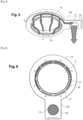
- the annular chamber is delimited by walls forming, in the active configuration of the container, one, a bottom wall of the annular chamber facing the bottom of the container, the air intake orifices of the annular chamber which are arranged in said bottom wall have the shape of curved slots with concavity facing the filling opening surrounded by said annular chamber, said air intake orifices being distributed circumferentially around said filling opening.
- the annular chamber communicates with the fluid connection in an area called the communication area and the air intake orifices of the annular chamber remote from said communication area have an opening area of greater dimension than the opening area of the air intake orifices of the annular chamber closer to the communication area. This design allows for uniform air suction over the entire circumference of the annular chamber.
- the so-called double-skinned column is a column whose peripheral surface connecting the top and the base of the column and serving to delimit the cavity of the column inside which the forced air circulation device is housed is formed by a double wall.
- the forced air circulation device divides the interior of the column into two sections, respectively called lower and upper, extending one above the other in the active configuration of the container.
- the container comprises at least one filter arranged inside said column, the or at least one of the filters being accessible through a filter access opening provided in the peripheral surface connecting the top and the base of the column and serving to delimit the cavity of the column, this access opening being closed by a hatch.
- This filter is optional in particular when the air outlet of the column is connected to a pre-existing air suction network incorporating at least one filter.
- At least the cover and the column are high-density polyethylene parts, preferably rotationally molded. This results in simplicity of manufacture.
- the annular chamber, the filling opening and the fluid connection can be made from a single piece.
- the container comprises a sealing gasket formed of one or more seals interposed on the one hand, between the cover and the column, on the other hand, between the cover and the body, in the active configuration of the container, to allow a sealed circulation of a flow of fluid from the inside of the body to the column via the annular chamber.
- a sealing gasket limits the risks of suction of unpolluted outside air. This again results in increased efficiency.
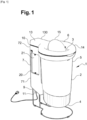
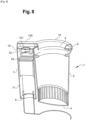
- the generally toxic waste container 1 of the invention may be of the type shown in figures 1 , 4 And 8 .
- This container 1 includes a body 2 hollow tubular section, here circular, in the form of a container open at the top.
- This hollow body 2 therefore has a lower part forming a bottom 4 and an upper part 5 for access to the interior of the body 2.
- the container 1 also comprises a filling opening 3 through which the waste can be introduced to be collected and stored in the body 2.
- the filling opening is arranged in the upper part of the body 2 or above the body 2.
- the body 2 is generally lined with a waste collection bag 23.
- the body 2 may be equipped in the upper part 5 with a system 25 for holding the bag 23 in the open state in the body 2.
- This holding system 25 is, in the example shown in Figure 7 , formed of two hoops, generally metallic, pivoting around an axis transverse to the body 2. These hoops form in one position, a circle extending in a plane substantially parallel to the bottom 4 of the body 2.
- the bag 23 is thus held in a position in which it follows the wall of the body 2 and presents its upper part in the open position.
- the container 1 further comprises an annular chamber 6 extending around the filling opening 3 and surrounding at least partially, preferably completely, the filling opening 3.
- This annular chamber 6 is provided with air intake orifices 8 arranged opposite the bottom 4 of the body 2 in a so-called active configuration of the container 1, conforming to that shown in FIG. Figure 1 .
- the filling opening 3 is provided in a cover 14.
- the cover 14 is a pivoting cover mounted on the body 2 which can pivot between a position close to and a position separated from the body 2.
- the position close to the body 2 corresponds to the active configuration of the container 1.
- This cover 14 could, in a similar manner, have been mounted so as to slide, for example.
- the cover 14 is coupled to the rest of the container by a hinge for its pivoting mounting.
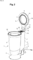
- the cover 14 is therefore pivotally movable for the passage from a position close to the body 2, in which it rests against the upper part of the body 2, to a position separated from the body 2 such that as illustrated in the Figure 2
- the position in which the cover 14 is moved away from the body 2 corresponds to the inactive configuration of the container 1.
- the hood 14 comprises a frame surrounding the filling opening 3.
- the frame is a hollow thick frame.
- the frame constitutes the annular chamber 6.
- the container 1 comprises a valve 15 for closing the filling opening 3.
- This valve 15 is mounted inside the frame which can pivot between an open position and a closed position of said filling opening 3.
- This valve 15 is in the form of a circular plate with a shape complementary to the filling opening 3 which is also shown as circular. This valve 15 is more particularly visible at Figure 1 .
- the annular chamber 6 is delimited by walls forming, in the active configuration of the container 1, one, a bottom wall 16 of the annular chamber 6 facing the bottom of the container 1.
- the air intake orifices 8 of the annular chamber 6 are arranged in this bottom wall 16.
- These air intake orifices 8 each have the shape of a curved slot with a concavity facing the filling opening 3 surrounded by the annular chamber 6.
- These air intake orifices 8 are distributed circumferentially around the filling opening 3.
- the filling opening 3 is circular in shape and the air intake orifices 8 are arranged on a circle around the filling opening 3.
- the circle is a circle with a center passing through the center of the filling opening 3.
- the container 1 finally comprises a hollow column 7 which is adjoining, that is to say adjacent, to the body 2, to extend along the body 2 outside the body 2.
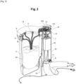
- This column 7 comprises a base 9, a top 10 and at least one air outlet 11 which is, in the example shown, arranged at the base 9 of the column 7, as can be seen in the Figure 3 .
- column 7 includes a top 10 and a base 9 as well as an air outlet 11.
- This air outlet 11 can open into the open air, as in the Figure 2 , or be connected to a fluid circulation network, as illustrated in Figure 3 .
- This column 7 is, in the examples shown, open at its top 10 and at its base 9.
- This column 7 is, in the examples shown, of square external section, but could have been circular or other without departing from the scope of the invention.
- a base allows column 7 and body 2 to be kept in an upright position, i.e. vertical.
- the base of the column 7 extends above the ground in the upright position of the assembly.
- This column 7 houses a forced air circulation device 12 generally in the form of a fan.
- This forced air circulation device 12 divides the interior of the column 7 into two sections called, respectively, lower 71 and upper 72. These lower 71 and upper 72 sections extend one above the other in the active configuration of the container 1 in which the column 7 extends in the upright state.
- the forced air circulation device 12 is preferably positioned in the upper section 72 of the column 7 to be as close as possible to the annular chamber 6.
- a grid 24 may be provided between the top of the column 7 which is open and the forced air circulation device 12. This prevents an operator from injuring his fingers by contact with the forced air circulation device 12 in the non-active configuration of the container 1.
- the cover 14 and the column 7 are high-density polyethylene parts, preferably rotationally molded, i.e. manufactured by rotational molding. The production of a part by rotational molding is visible on the final part.
- the container 1 may comprise at least one filter 19 arranged inside the column 7.
- This filter 19 may be accessible through an opening 20 for access to the filter 19 formed in the peripheral surface connecting the top 10 and the base 9 of the column 7, and serving to delimit the cavity of the column 7. In in the examples shown, this access opening 20 is closed by a hatch 21. Such a filter 19 is visible at Figure 3 .
- the column 7 may be without a filter and the filter may be arranged on the air circulation circuit of the type shown in Figure 3 which connects the air outlet of column 7 provided at the base of column 7 to a pre-existing air circulation circuit.
- the column 7 can be a so-called double-skinned column.
- the peripheral surface connecting the top 10 and the base 9 of the column 7, and serving to delimit the cavity of the column 7 inside which the forced air circulation device 12 is housed can be formed by a double wall 18.
- the electrical wiring, as well as any element potentially disrupting the air flow can be arranged between the two walls. The air flow generated by the forced air circulation device 12 is thus subject to minimal disturbance inside the column 7.
- the column 7 is, in the active configuration of the container, that is to say in the configuration in which the air intake orifices 8 of the annular chamber 6 are arranged opposite the bottom 4 of the body 2, in fluid communication with the annular chamber 6 by an airtight fluid connection 13, to enable a channeled air flow to be generated from the interior of the body 2 to the interior of the column 7 via the annular chamber 6.
- This active configuration also corresponds to the position in which the cover 14 is close to the body 2 and in particular rests on the body 2 and on the top of the column 7.
- the container 1 comprises a sealing gasket 22.
- This sealing gasket 22 may be formed of one or more seals. These seals are interposed, on the one hand, between the cover 14 and the column 7, on the other hand, between the cover 14 and the body 2, in the active configuration of the container 1 to allow a sealed circulation of a flow of fluid from the inside of the body 2 to the column 7 via the annular chamber 6.
- the hood In the non-active configuration of container 1, as shown in Figure 2 , the hood is in a position separated from the body 2 and the annular chamber 6 is no longer in fluid communication via the fluid connection 13 with the top of the column 7, so that the air potentially loaded with toxic gas contained in the body 2 can be released into the environment.
- the fluid connection 13 allowing fluid communication between the annular chamber 6 and the column 7, opens into the column 7 at the top 10 of the column 7, and the forced air circulation device 12 is configured to generate an air flow from the top 10 towards the base 9 of said column 7.
- the fluid connection 13, for fluid communication between the annular chamber 6 and the column 7, is formed by an external radial protrusion 130 of the annular chamber 6.
- This external radial protrusion 130 is in the form of a blind conduit, that is to say a conduit one of the end faces of which is closed.
- This conduit is delimited by a peripheral wall provided with an outlet orifice 131 positioned opposite the open top 10 of the column 7 in the active configuration of the container 1, that is to say in the configuration in which this external radial protrusion 130 bears on the top of the column 7.
- the open end face of the blind conduit opens into the annular chamber 6.
- the annular chamber 6 communicates with the fluid connection 13 in a zone called the communication zone 17.
- This communication zone 17 corresponding to the open end face of the blind conduit.
- the orifices 8 air intake orifices of the annular chamber 6 remote from the communication zone 17 have an opening area of greater dimension than the opening area of the air intake orifices 8 close to the communication zone 17. This results in homogeneity of the air inside the annular chamber 6.
- the annular chamber 6 and the fluid connection form the cover 14 which is made from a single piece. This part is, as mentioned above, preferably manufactured by rotational molding.
- the hood In the active configuration of container 1, the hood is in a position close to body 2 and rests on body 2 and column 7, as illustrated in Figure 1 .
- the electrical forced air circulation device 12 is operated thanks to the presence of an on/off switch preferably arranged on the column 7. This forced air circulation device 12 permanently generates an air flow from the body 2 to the air outlet 11 of the column 7 in the active configuration of the container 1.
- the air potentially laden with toxic gas and contained in the body 2 is sucked into the annular chamber 6 through the air intake orifices 8, passes from the annular chamber 6 to the top 10 of the column 7 via the fluid connection 13, travels through the column 7 from the top 10 to the base 9 of the column 7 to exit the column 7 through the air outlet 11 of the column 7 formed in the base 9 of the column 7, this base 9 being spaced from the ground.
- Such a waste container 1 can be used for the collection of toxic waste without the release of toxic gas into the environment.
Landscapes
- Engineering & Computer Science (AREA)
- Mechanical Engineering (AREA)
- Apparatus Associated With Microorganisms And Enzymes (AREA)
- Details Of Rigid Or Semi-Rigid Containers (AREA)
Applications Claiming Priority (1)
| Application Number | Priority Date | Filing Date | Title |
|---|---|---|---|
| FR2310248A FR3153340B1 (fr) | 2023-09-27 | 2023-09-27 | Conteneur à déchets, notamment pour la collecte de déchets toxiques, tels que ceux issus de laboratoire |
Publications (3)
| Publication Number | Publication Date |
|---|---|
| EP4530222A1 true EP4530222A1 (de) | 2025-04-02 |
| EP4530222B1 EP4530222B1 (de) | 2026-03-04 |
| EP4530222C0 EP4530222C0 (de) | 2026-03-04 |
Family
ID=89158425
Family Applications (1)
| Application Number | Title | Priority Date | Filing Date |
|---|---|---|---|
| EP24202121.0A Active EP4530222B1 (de) | 2023-09-27 | 2024-09-24 | Abfallbehälter, insbesondere zur sammlung von toxischem abfall, wie laboratorien |
Country Status (2)
| Country | Link |
|---|---|
| EP (1) | EP4530222B1 (de) |
| FR (1) | FR3153340B1 (de) |
Citations (6)
| Publication number | Priority date | Publication date | Assignee | Title |
|---|---|---|---|---|
| US20050230407A1 (en) | 2004-03-26 | 2005-10-20 | Chun-Li Fang | Toxic waste receptacle |
| CN105836344A (zh) * | 2016-06-22 | 2016-08-10 | 厦门唯科健康科技有限公司 | 带吸尘功能的智能垃圾桶 |
| US10058222B1 (en) | 2017-01-04 | 2018-08-28 | Brian M. Willer | Particle remover for receptacle |
| CN111498338A (zh) * | 2019-01-31 | 2020-08-07 | 台山市捷达电器有限公司 | 垃圾桶 |
| US20200339344A1 (en) | 2019-04-26 | 2020-10-29 | Yongkang Sippon Electric Co.,Ltd. | Garbage-can-type dust collector |
| US20230129640A1 (en) | 2021-10-26 | 2023-04-27 | Samsung Electronics Co., Ltd. | Food waste disposer |
-
2023
- 2023-09-27 FR FR2310248A patent/FR3153340B1/fr active Active
-
2024
- 2024-09-24 EP EP24202121.0A patent/EP4530222B1/de active Active
Patent Citations (6)
| Publication number | Priority date | Publication date | Assignee | Title |
|---|---|---|---|---|
| US20050230407A1 (en) | 2004-03-26 | 2005-10-20 | Chun-Li Fang | Toxic waste receptacle |
| CN105836344A (zh) * | 2016-06-22 | 2016-08-10 | 厦门唯科健康科技有限公司 | 带吸尘功能的智能垃圾桶 |
| US10058222B1 (en) | 2017-01-04 | 2018-08-28 | Brian M. Willer | Particle remover for receptacle |
| CN111498338A (zh) * | 2019-01-31 | 2020-08-07 | 台山市捷达电器有限公司 | 垃圾桶 |
| US20200339344A1 (en) | 2019-04-26 | 2020-10-29 | Yongkang Sippon Electric Co.,Ltd. | Garbage-can-type dust collector |
| US20230129640A1 (en) | 2021-10-26 | 2023-04-27 | Samsung Electronics Co., Ltd. | Food waste disposer |
Also Published As
| Publication number | Publication date |
|---|---|
| EP4530222B1 (de) | 2026-03-04 |
| FR3153340B1 (fr) | 2025-09-26 |
| EP4530222C0 (de) | 2026-03-04 |
| FR3153340A1 (fr) | 2025-03-28 |
Similar Documents
| Publication | Publication Date | Title |
|---|---|---|
| CA2134056C (fr) | Ensemble de distribution a chambre de compression a volume variable a membrane | |
| BE1014903A5 (fr) | Compresseur a volutes comprenant une soupape anti-retour situee pres de l'orifice de decharge. | |
| EP3028957B1 (de) | Umkehrbarer deckel und behälter, der eine lebensmitteldose mit variablem volumen bildet | |
| FR2898770A1 (fr) | Dispositif de commande de coupure et de refoulement de l'eau pour arroseurs. | |
| FR2831875A1 (fr) | Bouchon de reservoir | |
| FR2960222A1 (fr) | Kit de distribution d'un produit fluide comprenant une poche et un boitier de distribution | |
| FR2540754A1 (fr) | Dispositif permettant le nettoyage d'une tete de remplissage sans demontage de celle-ci | |
| EP4107089B1 (de) | Behälter zur konservierung unter vakuum und vakuumbeschichtungssystem mit einem solchen behälter | |
| EP4530222B1 (de) | Abfallbehälter, insbesondere zur sammlung von toxischem abfall, wie laboratorien | |
| EP2335796B1 (de) | Ölfiltervorrichtung und eine solche Vorrichtung umfassendes Fahrzeug | |
| WO2016096659A1 (fr) | Clapet de reservoir de liquide de frein pour un maitre-cylindre | |
| EP0333607A1 (de) | Vorrichtung zur dynamischen Begrenzung | |
| EP3552215A1 (de) | Verpackung zum transport und/oder zur lagerung von radioaktiven substanzen mit einem verbesserten system zur fluidischen kommunikation zwischen dem inneren und dem äusseren des behälters | |
| EP3686359B1 (de) | Siphon mit sperrwasserhöhe, der einen luftdurchlass aufweist, und mit einem solchen siphon ausgestattete sanitärausstattung | |
| EP3893637B1 (de) | Deckel für einen tank mit entlüftung, mit schwimmer und ablenkplatte | |
| EP3529168B1 (de) | Vorrichtung zur auswahl von gasen für einen behälter zur lagerung verderblicher produkte | |
| FR3057819B1 (fr) | Vehicule comprenant une butee pour ouvrant permettant un ecoulement d’eau controle | |
| FR3136453A1 (fr) | Boîte destinée à la conservation sous vide de matière organique | |
| CH590768A5 (en) | Tank for transporting two different bulk products - has chambers separated by central flexible membrane extending into some or all of tank capacity | |
| EP4410158A1 (de) | Wasserkocher | |
| FR3166197A1 (fr) | Boîtier aéraulique pour la circulation de deux flux d’air séparés et système de pompe à chaleur équipé d’un tel boîtier | |
| FR2801874A1 (fr) | Couvercle a event integre | |
| FR2763387A1 (fr) | Dispositif d'injection de gaz pour l'aide au tirage dans un systeme de transport de fluide gazeux | |
| EP3704320A1 (de) | Belüftete klappe | |
| FR3031660A1 (fr) | Dispositif de traitement et d'aeration de matelas |
Legal Events
| Date | Code | Title | Description |
|---|---|---|---|
| PUAI | Public reference made under article 153(3) epc to a published international application that has entered the european phase |
Free format text: ORIGINAL CODE: 0009012 |
|
| STAA | Information on the status of an ep patent application or granted ep patent |
Free format text: STATUS: THE APPLICATION HAS BEEN PUBLISHED |
|
| AK | Designated contracting states |
Kind code of ref document: A1 Designated state(s): AL AT BE BG CH CY CZ DE DK EE ES FI FR GB GR HR HU IE IS IT LI LT LU LV MC ME MK MT NL NO PL PT RO RS SE SI SK SM TR |
|
| STAA | Information on the status of an ep patent application or granted ep patent |
Free format text: STATUS: REQUEST FOR EXAMINATION WAS MADE |
|
| 17P | Request for examination filed |
Effective date: 20250708 |
|
| GRAP | Despatch of communication of intention to grant a patent |
Free format text: ORIGINAL CODE: EPIDOSNIGR1 |
|
| STAA | Information on the status of an ep patent application or granted ep patent |
Free format text: STATUS: GRANT OF PATENT IS INTENDED |
|
| INTG | Intention to grant announced |
Effective date: 20251023 |
|
| GRAS | Grant fee paid |
Free format text: ORIGINAL CODE: EPIDOSNIGR3 |
|
| GRAA | (expected) grant |
Free format text: ORIGINAL CODE: 0009210 |
|
| STAA | Information on the status of an ep patent application or granted ep patent |
Free format text: STATUS: THE PATENT HAS BEEN GRANTED |
|
| AK | Designated contracting states |
Kind code of ref document: B1 Designated state(s): AL AT BE BG CH CY CZ DE DK EE ES FI FR GB GR HR HU IE IS IT LI LT LU LV MC ME MK MT NL NO PL PT RO RS SE SI SK SM TR |
|
| REG | Reference to a national code |
Ref country code: CH Ref legal event code: F10 Free format text: ST27 STATUS EVENT CODE: U-0-0-F10-F00 (AS PROVIDED BY THE NATIONAL OFFICE) Effective date: 20260304 Ref country code: GB Ref legal event code: FG4D Free format text: NOT ENGLISH |
|
| REG | Reference to a national code |
Ref country code: IE Ref legal event code: FG4D Free format text: LANGUAGE OF EP DOCUMENT: FRENCH |
|
| REG | Reference to a national code |
Ref country code: DE Ref legal event code: R096 Ref document number: 602024002985 Country of ref document: DE |