EP4528481A1 - Knotenaktualisierungsverfahren und -vorrichtung - Google Patents
Knotenaktualisierungsverfahren und -vorrichtung Download PDFInfo
- Publication number
- EP4528481A1 EP4528481A1 EP22948466.2A EP22948466A EP4528481A1 EP 4528481 A1 EP4528481 A1 EP 4528481A1 EP 22948466 A EP22948466 A EP 22948466A EP 4528481 A1 EP4528481 A1 EP 4528481A1
- Authority
- EP
- European Patent Office
- Prior art keywords
- software package
- target node
- node
- upgrade
- upper computer
- Prior art date
- Legal status (The legal status is an assumption and is not a legal conclusion. Google has not performed a legal analysis and makes no representation as to the accuracy of the status listed.)
- Pending
Links
Images




Classifications
-
- G—PHYSICS
- G06—COMPUTING OR CALCULATING; COUNTING
- G06F—ELECTRIC DIGITAL DATA PROCESSING
- G06F8/00—Arrangements for software engineering
- G06F8/60—Software deployment
- G06F8/65—Updates
-
- G—PHYSICS
- G07—CHECKING-DEVICES
- G07C—TIME OR ATTENDANCE REGISTERS; REGISTERING OR INDICATING THE WORKING OF MACHINES; GENERATING RANDOM NUMBERS; VOTING OR LOTTERY APPARATUS; ARRANGEMENTS, SYSTEMS OR APPARATUS FOR CHECKING NOT PROVIDED FOR ELSEWHERE
- G07C5/00—Registering or indicating the working of vehicles
- G07C5/008—Registering or indicating the working of vehicles communicating information to a remotely located station
Definitions
- This application relates to the field of vehicle diagnosis information technologies, and in particular, to a node upgrade method and apparatus.
- UDS Unified Diagnostic Services
- the primary control node directly transparently transmits, to a lower-layer node, a flashing requirement sent by an upper computer of a vehicle enterprise.
- the primary control node and all the secondary nodes need to match different protocols for customized development, resulting in high development costs and a long development period.
- This application provides a node upgrade method and apparatus, to reduce workloads of an upper computer and a secondary node, and reduce research and development costs and production costs.
- the method further includes: storing a current software package of the target node. After the sending the upgrade software package for the target node to the target node in the foregoing step, the method further includes: after the target node fails to be upgraded, sending the current software package to the target node and report error information, where the error information indicates that the target node fails to be upgraded.
- the primary control node reserves code of the secondary node in a data downloading phase as a rollback backup area. Backup code of all the secondary nodes is reserved in memory space of the primary control node. After flashing of all the secondary nodes is completed, the primary control node clears the backup code. If flashing of a secondary node fails, the primary control node feeds back the specific node with a flashing error to the upper computer, and rolls back backup software of the failed secondary node, to ensure that the secondary node with a flashing failure has functional software, and prevent a breakdown phenomenon that a lower-layer node has no functional software because an original program of the lower-layer node is erased and flashing of a new version of software fails. This improves flashing reliability and ensures normal running of a control system.
- the method further includes: after the target node is successfully upgraded, clearing the current software package.
- the primary control node may directly delete the current software package stored in the rollback backup area, to save memory resources of the primary control node.
- a first flag or a second flag is set for the current software package.
- the first flag indicates to send the current software package to the target node, and the second flag indicates to clear the current software package.
- the method further includes: performing secure access verification with the upper computer; and/or performing secure access verification with the target node.
- the target node does not need to interact with the upper computer. This reduces a matching workload of the secondary node.
- the method further includes: performing a post-programming phase, where the post-programming phase is used to restore a local communication status.
- the post-programming phase starts. This phase is completely performed by the primary control node. A response is made to a service instruction from the upper computer; necessary reset work is completed; communication between the primary control node and other nodes is restarted; DTC is enabled; DTC is cleared; and a diagnosis session jumps, to restore a communication status of the primary control node.
- the target node does not need to be developed by matching diagnosis and flashing standards of different vehicle enterprises. This reduces a development workload.
- a node upgrade method including: receiving a diagnosis request from an upper computer, where the diagnosis request includes a target identifier; feeding back, to the upper computer, version information of a target node corresponding to the target identifier; receiving an upgrade software package from the upper computer; and sending the upgrade software package to the target node.
- a response made by the control node on behalf of the target node and necessary conversion of the information ensure freedom of the target node, so that the target node can be designed on a platform.
- a programming phase only a software package of the target node needs to be downloaded.
- a primary control node needs to establish UDS communication with a single target node.
- This solution has a low requirement on memory for software storage, and reduces diagnosis and flashing load of the primary control node.
- a post-programming phase starts. This phase is completely performed by the primary control node.
- a response is made to a service instruction from the upper computer, and necessary reset work is completed.
- the target node does not need to be developed by matching UDS diagnosis and flashing standards of different vehicle enterprises.
- the method further includes: storing a current software package of the target node. After the sending the upgrade software package for the target node to the target node in the foregoing step, the method further includes: after the target node fails to be upgraded, sending the current software package to the target node and reporting error information, where the error information indicates that the target node fails to be upgraded.
- the method further includes: after the target node is successfully upgraded, clearing the current software package.
- a first flag or a second flag is set for the current software package.
- the first flag indicates to send the current software package to the target node, and the second flag indicates to clear the current software package.
- the method further includes: performing secure access verification with the upper computer; and/or performing secure access verification with the target node.
- the method further includes: performing a post-programming phase, where the post-programming phase is used to restore a local communication status.
- a node upgrade apparatus is provided, to implement the method according to any one of the first aspect or the possible implementations of the first aspect.
- the apparatus includes a corresponding unit or module configured to perform the method.
- the unit or module included in the apparatus may be implemented by software and/or hardware.
- the apparatus may be a network device, or may be a chip, a chip system, a processor, or the like that supports a network device in implementing the foregoing method, or may be a logic module or software that can implement all or some functions of a network device.
- a node upgrade apparatus is provided, to implement the method according to any one of the second aspect or the possible implementations of the second aspect.
- the apparatus includes a corresponding unit or module configured to perform the method.
- the unit or module included in the apparatus may be implemented by software and/or hardware.
- the apparatus may be a network device, or may be a chip, a chip system, a processor, or the like that supports a network device in implementing the foregoing method, or may be a logic module or software that can implement all or some functions of a network device.
- a computer device including a processor.
- the processor is coupled to a memory.
- the memory is configured to store instructions.
- the computer device is enabled to implement the method according to any one of the first aspect or the possible implementations of the first aspect.
- the computer device may be, for example, a network device, or may be a chip or a chip system that supports a network device in implementing the foregoing method.
- a computer device including a processor.
- the processor is coupled to a memory.
- the memory is configured to store instructions.
- the computer device is enabled to implement the method according to any one of the second aspect or the possible implementations of the second aspect.
- the computer device may be, for example, a network device, or may be a chip or a chip system that supports a network device in implementing the foregoing method.
- a computer-readable storage medium stores instructions. When the instructions are executed by a processor, the method provided in any one of the first aspect or the possible implementations of the first aspect and the second aspect or the possible implementations of the second aspect is implemented.
- a computer program product includes computer program code.
- the method provided in any one of the first aspect or the possible implementations of the first aspect and the second aspect or the possible implementations of the second aspect is implemented.
- a terminal device is provided.
- the terminal device may be a vehicle or an electronic component, and the terminal device includes the apparatus according to the third aspect or the fourth aspect.
- a chip system includes a processor.
- the processor is coupled to a memory.
- the processor executes a computer program stored in the memory, to perform steps of the method according to any one of the first aspect or the possible implementations of the first aspect and the second aspect or the possible implementations of the second aspect.
- the chip system may be a single chip or a chip module including a plurality of chips.
- Embodiments of this application provide a node upgrade method and apparatus, to reduce workloads of an upper computer and a secondary node, and reduce research and development costs and production costs.
- ECU Electronic control unit
- the ECU is also referred to as an in-vehicle computer or a vehicle-mounted computer, or referred to as a dedicated microcomputer controller or dedicated single-chip microcomputer for a vehicle in terms of use. Similar to a common computer, the ECU includes a microprocessor (microcontroller Unit, MCU), a read-only memory (read-only memory, ROM), a random access memory (random access memory, RAM), an input/output interface (I/O), an analog-to-digital (A/D) converter, and a large-scale integrated circuit, for example, a shaping or drive circuit.
- MCU microprocessor
- read-only memory read-only memory
- RAM random access memory
- I/O input/output interface
- A/D analog-to-digital
- A/D analog-to-digital converter
- a central processing unit (central processing unit, CPU) is a core part, and has functions of computation and control. For example, when an engine is running, the CPU collects signals of all sensors for computation, and converts a result of computation into a control signal, to control work of a controlled object.
- the CPU further controls a memory (for example, the ROM), the I/O, and another external circuit.
- the ECU generally has functions of fault self-diagnosis and protection. When a fault occurs in a system, the ECU automatically records a fault code in the RAM, and takes a protection measure to read an alternative program from an inherent program, to maintain running of a corresponding component (for example, the engine). The fault information is displayed on a dashboard and remains unchanged.
- the RAM continuously records data during a driving process of the vehicle, and learns the data recorded in real time by using an adaptive program, to provide an optimal control status for the vehicle owner to adapt to a driving habit.
- a conventional ECU has a simple structure, and an entire vehicle may have dozens of or hundreds of ECUs, for example, an ECU applied to an engine and an ECU applied to an antilock braking system. Functions of each ECU are independent.
- ECUs on the vehicle gradually become complex and tend to be centralized on a super ECU, resulting in increasing difficulty in diagnosing the ECUs.
- the upper computer is a computer device that may directly send a control command.
- a computer device that can communicate with the ECU based on a UDS protocol may be referred to as an upper computer (which may also be referred to as a diagnostic instrument, a diagnostic machine, a diagnostic tool, or the like), for example, a smart handheld terminal device like a personal computer (personal computer, PC), a mobile phone, or a tablet computer, a smart wearable device like a smart band or a smart watch, or even a single-chip microcomputer, provided that the device can run corresponding diagnostic software.
- any device that can communicate with the ECU based on the UDS protocol may be used as the upper computer in embodiments of this application. This is not specifically limited herein.
- UDS international organization for standardization
- ISO international organization for standardization
- the UDS is oriented to an application layer in an open systems interconnection (open systems interconnection, OSI) model, and may be implemented on different vehicle buses (for example, a controller area network (controller area network, CAN), a local area network (local interconnect network, LIN), FlexRay, an ethernet (ethernet), and a K-line (K-line)).
- a controller area network controller area network
- CAN controller area network
- LIN local area network
- FlexRay an ethernet
- ethernet ethernet
- K-line K-line
- a set of instruments (usually referred to as an upper computer) is configured to analyze information and data inside an ECU of a current vehicle.
- a language used by the set of instruments to communicate with the ECU is the UDS (which is not the only method).
- FIG. 1 is a diagram of an architecture of a communication and transmission system according to an embodiment of this application.
- the communication system includes an upper computer 101 and an ECU 102 (which may include one or more ECUs, and FIG. 1 shows a case of one ECU).
- Corresponding diagnosis software 1011 (such as a CAN development environment (CANopen environment, CANoe) or vehicle UDS test software) runs on the upper computer 101. With the diagnosis software, a corresponding diagnostic service can be implemented between the ECU 102 and the upper computer 101 based on the UDS.
- the diagnosis software 1011 may send a diagnosis request to the ECU 102. In the communication system provided in embodiments of this application, a request queue is no longer needed.
- the diagnosis request generated by the diagnosis software 1011 may be directly sent to the ECU 102, and the ECU 102 may upgrade software based on the diagnosis request.
- an ECU directly transparently transmits, to a secondary node, a flashing requirement sent by an upper computer of a vehicle enterprise.
- the ECU and all the secondary nodes need to match different protocols for customized development, resulting in high development costs and a long development period.
- the primary control node in embodiments of this application may be the ECU or any node that can implement a function of the ECU.
- FIG. 2 is a schematic flowchart of the node upgrade method according to an embodiment of this application. The method includes the following steps.
- Step 201 An upper computer sends a diagnosis request to a primary control node, and correspondingly, the primary control node receives the diagnosis request from the upper computer.
- corresponding diagnosis software (such as CANoe or vehicle UDS test software) runs on the upper computer.
- the diagnosis software when a secondary node is connected to the primary control node, the upper computer may implement a corresponding diagnostic service based on UDS. First, the upper computer sends the diagnosis request to the primary control node, and the primary control node receives the diagnosis request.
- the primary control node receives the diagnosis request in a pre-programming phase.
- a diagnostic trouble code diagnostic trouble code, DTC
- a non-default session mode needs to be enabled in the pre-programming phase. This is completed by using a diagnostic session control (10h) service whose session type is an extended session mode. This request is sent to all secondary nodes through functional addressing by using a single-frame request packet.
- Secure access verification is used to ensure security of a flashing event and prevent software of a controller node from being maliciously tampered with.
- a common secure access mechanism is implemented by using a "seed" and a "key”.
- a programming event needs to complete a secure access process.
- a secure access 27h service is mandatory in an emission-related and security system. Before an upgrade software package is downloaded, it is mandatory to complete a secure access process, to ensure that only an authorized diagnostic instrument can perform a download operation.
- the primary control node separately performs secure access verification with the upper computer and the secondary node.
- the primary control node sends a seed to respond to a seed request packet from the upper computer, and compares whether a key in a key packet sent by the upper computer is consistent with a key stored (or computed) in the primary control node. Only when values are consistent, the primary control node determines access permission of the upper computer to a specific service and data of the primary control node and the secondary node of the primary control node. If development standards of some enterprises have a higher requirement on a security verification level, an internal 27h service verification step may be established between the primary control node and the secondary node. In this process, the primary control node serves as an upper computer, and establishes a secure access verification mechanism with a secondary node controller. Details are not described herein. This can also avoid a workload of multi-matching development of the secondary node.
- Step 202 The primary control node downloads a software package set from the upper computer based on the diagnosis request, where the software package set includes an upgrade software package for one or more secondary nodes, and each secondary node is in a one-to-one correspondence with a node identifier.
- the upper computer does not control a part and version information of the secondary node, version upgrade information of the secondary node is reflected in the software package set, and the primary control node controls software package information.
- the software package set includes the upgrade software package for some or all the secondary nodes of the primary control node.
- the upper computer may indicate, by using the diagnosis request, the primary control node to simultaneously upgrade all the secondary nodes of the primary control node, or indicate, by using the diagnosis request, the primary control node to upgrade some secondary nodes of the primary control node.
- Each secondary node corresponds to a node identifier. For example, this may be implemented in a configuration manner.
- the node identifier represents the secondary node.
- the primary control node may configure a number for the secondary node, and the number represents the corresponding secondary node.
- the node identifier may be an address of the secondary node, an ID obtained through function division of the secondary node, or the like. This is not limited herein.
- the software package set may also include an upgrade software package for the primary control node. The primary control node may directly download the software package set from the upper computer, split the software package set into an upgrade software package, and forward the upgrade software package to a target node, to upgrade software of the secondary node, or simultaneously upgrade software of the secondary node and software of the primary control node.
- the pre-programming phase information related to the secondary node is confirmed.
- the upper computer does not control the part and the version information of the secondary node.
- Version upgrade information of all the secondary nodes is reflected in the software package set locally packed by the primary control node.
- the primary control node controls the software package information, and indicates, by using only one group of diagnosis IDs, all the secondary nodes in the software package set to upgrade software.
- Step 203 The primary control node determines the upgrade software package for the target node based on a node identifier of the target node, where the upgrade software package for the target node is included in the software package set.
- the primary control node may determine that the secondary node needs to be upgraded, and the primary control node can divide the software package set into the upgrade software package based on the node identifier. In other words, the software package set is divided into one or more upgrade software packages.
- a flag is stored in a header or a packet trailer of the upgrade software package in the software package set, the flag is in a correspondence with the node identifier. The correspondence is stored in the primary control node.
- the primary control node may parse the upgrade software package in the software package set, to obtain the flag in the upgrade software package, so as to determine a correspondence between the upgrade software package and the secondary node, based on the correspondence between the flag and the node identifier, and then splits the software package set.
- the flag in the upgrade software package may alternatively directly indicate the secondary node. This is not limited herein.
- the upgrade software package corresponding to the target node is one of the one or more upgrade software packages obtained through division.
- the primary control node may determine, based on the node identifier of the target node, the upgrade software package for the target node from the foregoing upgrade software package obtained through division.
- Step 204 The primary control node sends the upgrade software package for the target node to the target node.
- the primary control node may send the determined upgrade software package to the corresponding target node.
- the primary control node implements software upgrade of the target node based on a current UDS diagnosis and flashing standard, and the target node does not need to match the UDS diagnosis and flashing standard.
- a bootloader (bootloader) of the primary control node establishes communication with UDS of the secondary node, first downloads flash drivers (FlashDrivers) of all the secondary nodes to memory space allocated by the primary control node, forwards the flash drivers to the target node based on an address identifier, then downloads application (application, APP) software of all the secondary nodes to the memory space allocated by the primary control node, and forwards the APP to the target node based on the address identifier.
- flashing reliability is high. If memory space for current diagnosis and flashing is insufficient, segment data for the target node may not be stored and may be directly forwarded to the corresponding target node. This saves the memory space. However, in this case, the flashing reliability is lower, and there is a risk of a flashing failure.
- different enterprises may evaluate advantages and disadvantages of solutions based on the actual situation, and select an appropriate solution.
- the primary control node may also download a FlashDriver and an APP of the primary control node to corresponding memory space of the primary control node, to upgrade software of the primary control node.
- the secondary nodes stop sending online device requests after completing flashing, and send positive responses to the primary control node.
- the primary control node positively responds to the upper computer, and the upper computer sends, to the primary control node, an instruction indicating to perform a programming dependency check. Then, the primary control node performs the programming dependency check, and responds for the programming dependency check on behalf of the secondary nodes.
- the upper computer sends an 11h service instruction to the primary control node, and the primary control node forwards the 11h service instruction to the secondary nodes, to reset the secondary nodes to make the software take effect.
- the primary control node and the secondary nodes can be simultaneously reset, or the primary control node can be reset later than the secondary nodes. In this way, when the secondary nodes jump out from the bootloader after reset, the secondary nodes do not need to jump from the APP again to complete software reset of all controllers.
- the primary control node needs to disconnect from another node and stop DTC to prevent a communication error and a DTC error.
- the upper computer may send instructions indicating the primary control node to perform a post-programming phase, restart communication between the primary control node and other nodes, enable the DTC, clear the DTC, and jumps a diagnosis session, to restore a communication status of the primary control node, so that the primary control node can be used normally.
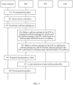
- a primary control node is a thermal system drive unit (thermal drive unit, TDU) in an ECU
- secondary nodes of the TDU are a positive temperature coefficient (positive temperature coefficient, PTC) and an electric air-conditioning compressor (electric air-conditioning compressor, EAC).
- the solution mainly includes the following several core steps.
- Step 302 The TDU performs secure access verification with the upper computer.
- Step 303 The TDU downloads a software package set from the upper computer.
- Step 304 Obtain a software package for the PTC by splitting the software package set, and forward the software package to the PTC node based on a flashing target identified based on an address.
- Step 305 Obtain a software package for the EAC by splitting the software package set, and forward the software package to the EAC node based on the flashing target identified based on the address.
- Step 306 The TDU performs a programming dependency check based on an instruction from the upper computer.
- Step 307 The TDU delivers a reset instruction to make software take effect.
- Step 308 The TDU performs a post-programming phase based on an instruction from the upper computer. A sequence of performing step 304 and step 305 is not specified.
- dedicated memory space may be allocated on the primary control node as a rollback backup area to store a current software package of the secondary node. For example, after determining an upgrade software package corresponding to a target node, the primary control node may copy a current software package of the target node and store the current software package in the rollback backup area, and then send the upgrade software package for the target node to the target node. When a problem occurs during upgrade of the target node, the primary control node may provide the stored current software package for the target node to perform software rollback, and then generate error information and report the error information to the upper computer, to prompt that the target node fails to be upgraded.
- the primary control node reserves code of the secondary node in a data downloading phase as the rollback backup area. Backup code of all the secondary nodes is reserved in memory space of the primary control node. After flashing of all the secondary nodes is completed, the primary control node clears the backup code. If flashing of a secondary node fails, the primary control node feeds back the specific node with a flashing error to the upper computer, and rolls back backup software of the failed secondary node, to ensure that the secondary node with a flashing failure has functional software, and prevent a breakdown phenomenon that a lower-layer node has no functional software because an original program of the lower-layer node is erased and flashing of a new version of software fails. This improves flashing reliability and ensures normal running of a control system.
- the primary control node may directly delete the current software package stored in the rollback backup area, to save memory resources of the primary control node.
- the primary control node may further set a flag bit in the rollback backup area as a signpost, and indicate, by using a first flag on the flag bit, the primary control node to send the current software package to the target node, or indicate, by using a second flag, the primary control node to delete the current software package, to improve performing efficiency.
- the upper computer does not control a part and version information of the secondary node, version upgrade information of the secondary node is reflected in the software package set packed by the primary control node, and the primary control node controls software package information.
- a design manufacturer of a control unit only needs to ensure that correct software of the primary control node and software of each secondary node are encapsulated in the software package, and does not need to perform separate part and version control. This reduces development costs.
- the primary control node is responsible for splitting and identifying the target node and establishing UDS communication with the secondary nodes, to implement simultaneous upgrade of controllers. In other words, each vehicle enterprise does not need to define different diagnosis IDs to distinguish between and manage and control the primary control node and the secondary nodes. This reduces workloads of the upper computer and the secondary nodes, and reduces research and development costs and production costs.
- FIG. 4 is a flowchart of another node upgrade method according to an embodiment of this application. The method is described as follows.
- Step 401 An upper computer sends a diagnosis request to a primary control node, and correspondingly, the primary control node receives the diagnosis request from the upper computer, where the diagnosis request includes a target identifier.
- corresponding diagnosis software (such as CANoe or vehicle UDS test software) runs on the upper computer.
- the diagnosis software when a secondary node is connected to the primary control node, the upper computer may implement a corresponding diagnostic service based on UDS.
- the upper computer may perform the diagnostic service for a target node in the secondary node of the primary control node.
- the upper computer sends the diagnosis request to the primary control node, and the primary control node receives the diagnosis request.
- the diagnosis request includes the target identifier indicating the target node.
- the primary control node After receiving the diagnosis request from the upper computer, the primary control node separately performs secure access verification with the upper computer and the secondary node.
- the primary control node sends a seed to respond to a seed request packet from the upper computer, and compares whether a key in a key packet sent by the upper computer is consistent with a key stored (or computed) in the primary control node. Only when values are consistent, the primary control node determines access permission of the upper computer to a specific service and data of the primary control node and the secondary node of the primary control node. If development standards of some enterprises have a higher requirement on a security verification level, an internal 27h service verification step may be established between the primary control node and the secondary node. In this process, the primary control node serves as an upper computer, and establishes a secure access verification mechanism with a secondary node controller. Details are not described herein. This can also avoid a workload of multi-matching development of the secondary node.
- Step 402 The primary control node sends version information of the target node corresponding to the target identifier to the host computer.
- the version information may include one or more of a part number, a software version number, and a hardware version number of the secondary node.
- Version information of all secondary nodes is stored in the primary control node, and the primary control node responds to a 22h service instruction from the upper host computer.
- the primary control node may feed back a software version and a hardware version of the target node to the upper computer, and the secondary node does not need to interact with the upper computer.
- the upper computer may directly deliver the upgrade software package to the primary control node. This can not only implement control over the version information of the secondary node, but also avoid a workload of multi-matching development of the secondary node.
- Step 404 The primary control node sends the upgrade software package to the target node, where the target node corresponds to the target identifier.
- step 404 refer to the related descriptions of step 204 in the method embodiment shown in FIG. 2 . Details are not described herein again.
- a primary control node is a TDU in an ECU
- secondary nodes of the TDU are a PTC and an EAC
- the target node is the PTC.
- the solution mainly includes the following several core steps.
- Step 502 The TDU performs secure access verification with the upper computer.
- Step 503 The TDU downloads a software package of the PTC from the upper computer.
- Step 504 The TDU forwards the software package of the PTC to the PTC node based on a target node identified based on an address.
- Step 505 The TDU performs a programming dependency check based on an instruction from the upper computer, and responds to the check on behalf of the PTC.
- Step 506 The TDU delivers a reset instruction to make software take effect.
- Step 507 The TDU performs a post-programming phase based on an instruction from the upper computer.
- a secondary node may not be upgraded successfully when software is upgraded, to avoid impact on running of the secondary node
- dedicated memory space may be allocated in the primary control node as a rollback backup area to store software code of the target node.
- the rollback backup area is used. For details, refer to the related descriptions of the rollback backup area in the method embodiment in FIG. 2 , and details are not described herein again. This can prevent a breakdown phenomenon that the target node has no functional software because an original program of the target node is erased and flashing of a new version of software fails, thereby improving flashing reliability and ensuring normal running of a control system.
- the primary control node may directly delete the current software package stored in the rollback backup area, to save memory resources of the primary control node.
- the primary control node may further set a flag bit in the rollback backup area as a signpost, and indicate, by using a first flag on the flag bit, the primary control node to send the current software package to the target node, or indicate, by using a second flag, the primary control node to delete the current software package, to improve performing efficiency.
- the primary control node performs the pre-programming step, and stores one or more pieces of information such as part numbers, hardware version numbers, and software version numbers of all secondary node controllers in the primary control node.
- This design greatly reduces a constraint of a vehicle enterprise on a secondary node controller.
- the secondary node controllers may use same internal models, and the primary control node is responsible for mapping the internal models to corresponding number formats required by the vehicle enterprises.
- a response made by the control node on behalf of the target node and necessary conversion of the information ensure freedom of the target node, so that the target node can be designed on a platform.
- a programming phase only a software package of the target node needs to be downloaded.
- the primary control node needs to establish UDS communication with a single target node.
- This solution has a low requirement on memory for software storage, and reduces diagnosis and flashing load of the primary control node.
- a post-programming phase starts. This phase is completely performed by the primary control node. A response is made to a service instruction from the upper computer, and necessary reset work is completed.
- the target node does not need to be developed by matching UDS diagnosis and flashing standards of different vehicle enterprises.
- FIG. 6 is a schematic diagram of a structure of a node upgrade apparatus according to an embodiment of this application.
- the apparatus 60 includes:
- the receiving unit 601 of the apparatus 60 is configured to perform step 201 in the method embodiment in FIG. 2 .
- the downloading unit 602 of the apparatus 60 is configured to perform step 202 in the method embodiment in FIG. 2 .
- the determining unit 603 of the apparatus 60 is configured to perform step 203 in the method embodiment in FIG. 2 .
- the sending unit 604 of the apparatus 60 is configured to perform step 204 in the method embodiment in FIG. 2 . Details are not described herein again.
- the apparatus 60 may further include a storage unit 605.
- the storage unit 605 is specifically configured to store a current software package of the target node.
- the sending unit 604 is further configured to: after the target node fails to be upgraded, send the current software package to the target node, and report error information.
- the error information indicates that the target node fails to be upgraded.
- the apparatus 60 further includes a clearing unit 606.
- the clearing unit 606 is specifically configured to clear the current software package after the target node is successfully upgraded.
- a first flag or a second flag is set for the current software package.
- the first flag indicates to send the current software package to the target node, and the second flag indicates to clear the current software package.
- the apparatus 60 further includes a verification unit 607.
- the verification unit 607 is specifically configured to: perform secure access verification with the upper computer, and/or perform secure access verification with the target node.
- the apparatus 60 further includes a post-programming unit 608.
- the post-programming unit 608 is specifically configured to perform a post-programming phase.
- the post-programming phase is used to restore a local communication status.
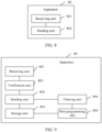
- FIG. 8 is a schematic diagram of a structure of another node upgrade apparatus according to an embodiment of this application.
- the apparatus 80 includes:
- the receiving unit 801 is further configured to receive an upgrade software package from the upper computer.
- the sending unit 802 is further configured to send the upgrade software package to the target node.
- the target node corresponds to the target identifier.
- the receiving unit 801 of the apparatus 80 is configured to perform step 401 and step 403 in the method embodiment in FIG. 4 .
- the sending unit 802 of the apparatus 80 is configured to perform step 402 and step 204 in the method embodiment in FIG. 4 . Details are not described herein again.
- the apparatus 80 may further include a storage unit 803.
- the storage unit 803 is specifically configured to store a current software package of the target node.
- the sending unit 802 is further configured to send the current software package to the target node after the target node fails to be upgraded.
- the apparatus 80 further includes a clearing unit 804.
- the clearing unit 804 is specifically configured to clear the current software package after the target node is successfully upgraded.
- a first flag or a second flag is set for the current software package.
- the first flag indicates to send the current software package to the target node, and the second flag indicates to clear the current software package.
- the apparatus 80 further includes a verification unit 805.
- the verification unit 805 is specifically configured to: perform secure access verification with an upper computer, and/or perform secure access verification with the target node.
- the apparatus 80 further includes a post-programming unit 806.
- the post-programming unit 806 is specifically configured to perform a post-programming phase.
- the post-programming phase is used to restore a local communication status.
- FIG. 10 is a schematic diagram of a possible logical structure of a computer device 100 according to an embodiment of this application.
- the computer device 100 includes a processor 1001, a communication interface 1002, a storage system 1003, and a bus 1004.
- the processor 1001, the communication interface 1002, and the storage system 1003 are connected to each other through the bus 1004.
- the processor 1001 is configured to control and manage an action of the computer device 100.
- the processor 1001 is configured to perform the steps performed by the primary control node in the method embodiment in FIG. 2 or FIG. 4 .
- the communication interface 1002 is configured to support the computer device 100 for communication.
- the storage system 1003 is configured to store program code and data of the computer device 100.
- the processor 1001 may be a central processing unit, a general-purpose processor, a digital signal processor, an application-specific integrated circuit, a field programmable gate array or another programmable logic device, a transistor logic device, a hardware component, or any combination thereof.
- the processor may implement or execute various example logical blocks, modules, and circuits described with reference to content disclosed in this application.
- the processor 1001 may be a combination of processors implementing a computing function, for example, a combination of one or more microprocessors, or a combination of a digital signal processor and a microprocessor.
- the bus 1004 may be a peripheral component interconnect (Peripheral Component Interconnect, PCI) bus, an extended industry standard architecture (Extended Industry Standard Architecture, EISA) bus, or the like.
- PCI peripheral component interconnect
- EISA Extended Industry Standard Architecture
- the bus may be classified into an address bus, a data bus, a control bus, and the like. For ease of representation, only one thick line is for representing the bus in FIG. 10 , but this does not mean that there is only one bus or only one type of bus.
- the receiving unit 601 and the sending unit 604 in the apparatus 60 are equivalent to the communication interface 1002 in the computer device 100.
- the downloading unit 602 and the determining unit 603 in the apparatus 60 are equivalent to the processor 1001 in the computer device 100.
- the receiving unit 801 and the sending unit 802 in the apparatus 80 are equivalent to the communication interface 1002 in the computer device 100.
- the computer device 100 in this embodiment may correspond to the primary control node in the method embodiment in FIG. 2 or FIG. 4 .
- the communication interface 1002 in the computer device 100 may implement functions and/or various steps implemented by the primary control node in the method embodiment in FIG. 2 or FIG. 4 . For brevity, details are not described herein again.
- division of the units in the foregoing apparatus is merely logical function division. During actual implementation, all or some of the units may be integrated into one physical entity, or may be physically separated.
- all the units in the apparatus may be implemented in a form of software invoked by a processing element, or may be implemented in a form of hardware; or some units may be implemented in a form of software invoked by a processing element, and some units may be implemented in a form of hardware.
- each unit may be a separately disposed processing element, or may be integrated into a chip of the apparatus for implementation.
- each unit may alternatively be stored in a memory in a form of program to be invoked by a processing element of the apparatus to perform a function of the unit.
- processing element herein may also be referred to as a processor, and may be an integrated circuit having a signal processing capability.
- steps in the foregoing methods or the foregoing units may be implemented by using a hardware integrated logic circuit in a processor element, or may be implemented in the form of software invoked by the processing element.
- the unit in any one of the foregoing apparatuses may be one or more integrated circuits configured to implement the foregoing methods, for example, one or more application-specific integrated circuits (application-specific integrated circuits, ASICs), or one or more microprocessors (digital signal processors, DSPs), or one or more field programmable gate arrays (field programmable gate arrays, FPGAs), or a combination of at least two of these integrated circuit forms.
- the processing element may be a general-purpose processor, for example, a central processing unit (central processing unit, CPU) or another processor that may invoke the program.
- the units may be integrated and implemented in a form of system-on-a-chip (system-on-a-chip, SOC).
- a computer-readable storage medium stores computer-executable instructions.
- a processor of a device executes the computer-executable instructions, the device performs the method performed by the primary control node in the foregoing method embodiments.
- a computer program product is further provided.
- the computer program product includes computer-executable instructions, and the computer-executable instructions are stored in a computer-readable storage medium.
- a processor of a device executes the computer-executable instructions, the device performs a method performed by the primary control node in the foregoing method embodiments.
- the disclosed system, apparatus, and method may be implemented in other manners.
- the described apparatus embodiments are merely examples.
- the division into units is merely logical function division and may be other division in practice.
- a plurality of units or components may be combined or integrated into another system, or some features may be ignored or not performed.
- the displayed or discussed mutual couplings or direct couplings or communication connections may be implemented by using some interfaces.
- the indirect couplings or communication connections between the apparatuses or units may be implemented in electronic, mechanical, or other forms.
- the units described as separate parts may or may not be physically separate, and parts displayed as units may or may not be physical units, may be located in one position, or may be distributed on a plurality of network units. Some or all of the units may be selected according to actual requirements to achieve the objectives of the solutions of embodiments.
- functional units in embodiments of this application may be integrated into one processing unit, each of the units may exist alone physically, or two or more units are integrated into one unit.
- the integrated unit may be implemented in a form of hardware, or may be implemented in a form of a software functional unit.
- the integrated unit When the integrated unit is implemented in the form of the software functional unit and sold or used as an independent product, the integrated unit may be stored in a computer-readable storage medium. Based on such an understanding, the technical solutions of this application essentially, or the part contributing to the conventional technology, or all or some of the technical solutions may be implemented in the form of a software product.
- the computer software product is stored in a storage medium and includes several instructions for instructing a computer device (which may be a personal computer, a server, or a network device) to perform all or some of the steps of the methods described in embodiments of this application.
- the foregoing storage medium includes any medium that can store program code, such as a USB flash drive, a removable hard disk, a read-only memory (ROM, read-only memory), a random access memory (RAM, random access memory), a magnetic disk, or an optical disc.
- program code such as a USB flash drive, a removable hard disk, a read-only memory (ROM, read-only memory), a random access memory (RAM, random access memory), a magnetic disk, or an optical disc.
Landscapes
- Engineering & Computer Science (AREA)
- Software Systems (AREA)
- General Engineering & Computer Science (AREA)
- Theoretical Computer Science (AREA)
- Physics & Mathematics (AREA)
- General Physics & Mathematics (AREA)
- Computer Security & Cryptography (AREA)
- Stored Programmes (AREA)
- Information Transfer Between Computers (AREA)
Applications Claiming Priority (1)
| Application Number | Priority Date | Filing Date | Title |
|---|---|---|---|
| PCT/CN2022/102664 WO2024000354A1 (zh) | 2022-06-30 | 2022-06-30 | 一种节点升级方法以及装置 |
Publications (2)
| Publication Number | Publication Date |
|---|---|
| EP4528481A1 true EP4528481A1 (de) | 2025-03-26 |
| EP4528481A4 EP4528481A4 (de) | 2025-08-13 |
Family
ID=89383522
Family Applications (1)
| Application Number | Title | Priority Date | Filing Date |
|---|---|---|---|
| EP22948466.2A Pending EP4528481A4 (de) | 2022-06-30 | 2022-06-30 | Knotenaktualisierungsverfahren und -vorrichtung |
Country Status (4)
| Country | Link |
|---|---|
| US (1) | US20250123834A1 (de) |
| EP (1) | EP4528481A4 (de) |
| CN (1) | CN117940893A (de) |
| WO (1) | WO2024000354A1 (de) |
Families Citing this family (3)
| Publication number | Priority date | Publication date | Assignee | Title |
|---|---|---|---|---|
| CN113238791B (zh) * | 2021-05-19 | 2024-08-02 | 上海艾拉比智能科技有限公司 | 一种主从架构的ota差分升级方法及系统 |
| CN118656099B (zh) * | 2024-08-21 | 2024-11-05 | 成都赛力斯科技有限公司 | 一种车辆控制器升级方法、系统及电子设备 |
| CN119484281A (zh) * | 2024-11-08 | 2025-02-18 | 重庆赛力斯凤凰智创科技有限公司 | 多个电子控制器单元的升级方法、装置、设备及存储介质 |
Family Cites Families (6)
| Publication number | Priority date | Publication date | Assignee | Title |
|---|---|---|---|---|
| JP2011148398A (ja) * | 2010-01-21 | 2011-08-04 | Denso Corp | 車両用プログラム更新システム |
| KR101966626B1 (ko) * | 2016-02-11 | 2019-04-09 | 현대자동차주식회사 | 차량용 무선 소프트웨어 업데이트 방법 및 장치 |
| WO2020032196A1 (ja) * | 2018-08-10 | 2020-02-13 | 株式会社デンソー | 車両情報通信システム |
| KR102273410B1 (ko) * | 2020-01-10 | 2021-07-06 | 성균관대학교산학협력단 | Ecu를 리프로그래밍 하기 위한 장치, 시스템 및 방법 |
| EP3893108B1 (de) * | 2020-02-14 | 2023-04-05 | Huawei Technologies Co., Ltd. | Verfahren zur aufrüstung einer fahrzeugmontierten vorrichtung und zugehörige einrichtung |
| CN114513438B (zh) * | 2022-02-08 | 2024-04-26 | 苏州挚途科技有限公司 | 空中下载测试系统及方法 |
-
2022
- 2022-06-30 WO PCT/CN2022/102664 patent/WO2024000354A1/zh not_active Ceased
- 2022-06-30 EP EP22948466.2A patent/EP4528481A4/de active Pending
- 2022-06-30 CN CN202280060827.4A patent/CN117940893A/zh active Pending
-
2024
- 2024-12-23 US US18/999,506 patent/US20250123834A1/en active Pending
Also Published As
| Publication number | Publication date |
|---|---|
| US20250123834A1 (en) | 2025-04-17 |
| WO2024000354A1 (zh) | 2024-01-04 |
| CN117940893A (zh) | 2024-04-26 |
| EP4528481A4 (de) | 2025-08-13 |
Similar Documents
| Publication | Publication Date | Title |
|---|---|---|
| US20250123834A1 (en) | Node upgrade method and apparatus | |
| US11223525B2 (en) | Gateway device, firmware update method, and recording medium | |
| US11599349B2 (en) | Gateway device, in-vehicle network system, and firmware update method | |
| US12169708B2 (en) | Gateway device, in-vehicle network system, and firmware update method | |
| US7493198B2 (en) | Method and device for a vehicle-related telematics service | |
| CN114327543A (zh) | 车载控制器的在线升级方法、装置、车辆及存储介质 | |
| KR102807028B1 (ko) | 차량의 온보드 버스에서 컴퓨터와 대화하는 방법 | |
| CN115469853A (zh) | 车辆远程控制功能的低代码开发方法、装置、设备及介质 | |
| US20230215226A1 (en) | Method for vehicle diagnostics, diagnostic connector, and diagnostic device | |
| EP4618488A1 (de) | Verfahren und vorrichtung zur steuergeräteaufrüstung | |
| CN119882967A (zh) | 多核异构soc复位方法、电子设备及芯片 | |
| CN116775375A (zh) | 数据存储的方法和系统 | |
| CN116431391A (zh) | 数据备份的方法、装置、车辆和存储介质 | |
| US12135960B2 (en) | Center, OTA master, method, non-transitory storage medium, and vehicle | |
| US20250286750A1 (en) | Communication interaction method, apparatus, device, and storage medium | |
| WO2023041036A1 (zh) | 处理器诊断装置、处理器诊断方法和电子设备 | |
| WO2025123680A1 (zh) | 一种车辆诊断仪、车辆诊断方法和系统 | |
| CN118394027A (zh) | 一种多控制器的诊断升级的方法及相关装置 | |
| JP2003280902A (ja) | マイコンロジック開発システム及びそのプログラム | |
| CN115080092A (zh) | 一种软件升级方法、装置及电子设备 | |
| CN117130635A (zh) | 一种诊断升级方法、诊断系统、电子设备及汽车 | |
| KR20250045809A (ko) | 차량 자가진단 시스템에서의 sw 업그레이드 인증 평가 방법 및 그에 따른 평가 시스템 | |
| JPH1196082A (ja) | 車両用メモリ書換え装置 | |
| CN118605914A (zh) | 固件升级方法、装置、计算机设备及可读存储介质 | |
| CN107729044A (zh) | 用于对车辆进行维护的方法和装置 |
Legal Events
| Date | Code | Title | Description |
|---|---|---|---|
| STAA | Information on the status of an ep patent application or granted ep patent |
Free format text: STATUS: THE INTERNATIONAL PUBLICATION HAS BEEN MADE |
|
| PUAI | Public reference made under article 153(3) epc to a published international application that has entered the european phase |
Free format text: ORIGINAL CODE: 0009012 |
|
| STAA | Information on the status of an ep patent application or granted ep patent |
Free format text: STATUS: REQUEST FOR EXAMINATION WAS MADE |
|
| 17P | Request for examination filed |
Effective date: 20241219 |
|
| AK | Designated contracting states |
Kind code of ref document: A1 Designated state(s): AL AT BE BG CH CY CZ DE DK EE ES FI FR GB GR HR HU IE IS IT LI LT LU LV MC MK MT NL NO PL PT RO RS SE SI SK SM TR |
|
| A4 | Supplementary search report drawn up and despatched |
Effective date: 20250711 |
|
| RIC1 | Information provided on ipc code assigned before grant |
Ipc: G06F 8/65 20180101AFI20250707BHEP Ipc: G07C 5/00 20060101ALI20250707BHEP |
|
| DAV | Request for validation of the european patent (deleted) | ||
| DAX | Request for extension of the european patent (deleted) |