EP4528087A1 - Bereichserweiterer für ein batterieelektrofahrzeug - Google Patents
Bereichserweiterer für ein batterieelektrofahrzeug Download PDFInfo
- Publication number
- EP4528087A1 EP4528087A1 EP24821731.7A EP24821731A EP4528087A1 EP 4528087 A1 EP4528087 A1 EP 4528087A1 EP 24821731 A EP24821731 A EP 24821731A EP 4528087 A1 EP4528087 A1 EP 4528087A1
- Authority
- EP
- European Patent Office
- Prior art keywords
- power generation
- crankshaft
- engine
- cylinders
- engine dedicated
- Prior art date
- Legal status (The legal status is an assumption and is not a legal conclusion. Google has not performed a legal analysis and makes no representation as to the accuracy of the status listed.)
- Pending
Links
Images


Classifications
-
- F—MECHANICAL ENGINEERING; LIGHTING; HEATING; WEAPONS; BLASTING
- F01—MACHINES OR ENGINES IN GENERAL; ENGINE PLANTS IN GENERAL; STEAM ENGINES
- F01L—CYCLICALLY OPERATING VALVES FOR MACHINES OR ENGINES
- F01L1/00—Valve-gear or valve arrangements, e.g. lift-valve gear
- F01L1/12—Transmitting gear between valve drive and valve
- F01L1/14—Tappets; Push rods
- F01L1/146—Push-rods
-
- F—MECHANICAL ENGINEERING; LIGHTING; HEATING; WEAPONS; BLASTING
- F01—MACHINES OR ENGINES IN GENERAL; ENGINE PLANTS IN GENERAL; STEAM ENGINES
- F01L—CYCLICALLY OPERATING VALVES FOR MACHINES OR ENGINES
- F01L1/00—Valve-gear or valve arrangements, e.g. lift-valve gear
- F01L1/12—Transmitting gear between valve drive and valve
- F01L1/18—Rocking arms or levers
-
- F—MECHANICAL ENGINEERING; LIGHTING; HEATING; WEAPONS; BLASTING
- F01—MACHINES OR ENGINES IN GENERAL; ENGINE PLANTS IN GENERAL; STEAM ENGINES
- F01L—CYCLICALLY OPERATING VALVES FOR MACHINES OR ENGINES
- F01L1/00—Valve-gear or valve arrangements, e.g. lift-valve gear
- F01L1/36—Valve-gear or valve arrangements, e.g. lift-valve gear peculiar to machines or engines of specific type other than four-stroke cycle
- F01L1/42—Valve-gear or valve arrangements, e.g. lift-valve gear peculiar to machines or engines of specific type other than four-stroke cycle for machines or engines characterised by cylinder arrangements, e.g. star or fan
-
- F—MECHANICAL ENGINEERING; LIGHTING; HEATING; WEAPONS; BLASTING
- F02—COMBUSTION ENGINES; HOT-GAS OR COMBUSTION-PRODUCT ENGINE PLANTS
- F02B—INTERNAL-COMBUSTION PISTON ENGINES; COMBUSTION ENGINES IN GENERAL
- F02B63/00—Adaptations of engines for driving pumps, hand-held tools or electric generators; Portable combinations of engines with engine-driven devices
- F02B63/04—Adaptations of engines for driving pumps, hand-held tools or electric generators; Portable combinations of engines with engine-driven devices for electric generators
-
- F—MECHANICAL ENGINEERING; LIGHTING; HEATING; WEAPONS; BLASTING
- F02—COMBUSTION ENGINES; HOT-GAS OR COMBUSTION-PRODUCT ENGINE PLANTS
- F02B—INTERNAL-COMBUSTION PISTON ENGINES; COMBUSTION ENGINES IN GENERAL
- F02B75/00—Other engines
- F02B75/16—Engines characterised by number of cylinders, e.g. single-cylinder engines
- F02B75/18—Multi-cylinder engines
- F02B75/24—Multi-cylinder engines with cylinders arranged oppositely relative to main shaft and of "flat" type
-
- F—MECHANICAL ENGINEERING; LIGHTING; HEATING; WEAPONS; BLASTING
- F02—COMBUSTION ENGINES; HOT-GAS OR COMBUSTION-PRODUCT ENGINE PLANTS
- F02D—CONTROLLING COMBUSTION ENGINES
- F02D29/00—Controlling engines, such controlling being peculiar to the devices driven thereby, the devices being other than parts or accessories essential to engine operation, e.g. controlling of engines by signals external thereto
- F02D29/06—Controlling engines, such controlling being peculiar to the devices driven thereby, the devices being other than parts or accessories essential to engine operation, e.g. controlling of engines by signals external thereto peculiar to engines driving electric generators
-
- B—PERFORMING OPERATIONS; TRANSPORTING
- B60—VEHICLES IN GENERAL
- B60K—ARRANGEMENT OR MOUNTING OF PROPULSION UNITS OR OF TRANSMISSIONS IN VEHICLES; ARRANGEMENT OR MOUNTING OF PLURAL DIVERSE PRIME-MOVERS IN VEHICLES; AUXILIARY DRIVES FOR VEHICLES; INSTRUMENTATION OR DASHBOARDS FOR VEHICLES; ARRANGEMENTS IN CONNECTION WITH COOLING, AIR INTAKE, GAS EXHAUST OR FUEL SUPPLY OF PROPULSION UNITS IN VEHICLES
- B60K6/00—Arrangement or mounting of plural diverse prime-movers for mutual or common propulsion, e.g. hybrid propulsion systems comprising electric motors and internal combustion engines
- B60K6/20—Arrangement or mounting of plural diverse prime-movers for mutual or common propulsion, e.g. hybrid propulsion systems comprising electric motors and internal combustion engines the prime-movers consisting of electric motors and internal combustion engines, e.g. HEVs
- B60K6/22—Arrangement or mounting of plural diverse prime-movers for mutual or common propulsion, e.g. hybrid propulsion systems comprising electric motors and internal combustion engines the prime-movers consisting of electric motors and internal combustion engines, e.g. HEVs characterised by apparatus, components or means specially adapted for HEVs
- B60K6/24—Arrangement or mounting of plural diverse prime-movers for mutual or common propulsion, e.g. hybrid propulsion systems comprising electric motors and internal combustion engines the prime-movers consisting of electric motors and internal combustion engines, e.g. HEVs characterised by apparatus, components or means specially adapted for HEVs characterised by the combustion engines
-
- B—PERFORMING OPERATIONS; TRANSPORTING
- B60—VEHICLES IN GENERAL
- B60K—ARRANGEMENT OR MOUNTING OF PROPULSION UNITS OR OF TRANSMISSIONS IN VEHICLES; ARRANGEMENT OR MOUNTING OF PLURAL DIVERSE PRIME-MOVERS IN VEHICLES; AUXILIARY DRIVES FOR VEHICLES; INSTRUMENTATION OR DASHBOARDS FOR VEHICLES; ARRANGEMENTS IN CONNECTION WITH COOLING, AIR INTAKE, GAS EXHAUST OR FUEL SUPPLY OF PROPULSION UNITS IN VEHICLES
- B60K6/00—Arrangement or mounting of plural diverse prime-movers for mutual or common propulsion, e.g. hybrid propulsion systems comprising electric motors and internal combustion engines
- B60K6/20—Arrangement or mounting of plural diverse prime-movers for mutual or common propulsion, e.g. hybrid propulsion systems comprising electric motors and internal combustion engines the prime-movers consisting of electric motors and internal combustion engines, e.g. HEVs
- B60K6/42—Arrangement or mounting of plural diverse prime-movers for mutual or common propulsion, e.g. hybrid propulsion systems comprising electric motors and internal combustion engines the prime-movers consisting of electric motors and internal combustion engines, e.g. HEVs characterised by the architecture of the hybrid electric vehicle
- B60K6/46—Series type
-
- Y—GENERAL TAGGING OF NEW TECHNOLOGICAL DEVELOPMENTS; GENERAL TAGGING OF CROSS-SECTIONAL TECHNOLOGIES SPANNING OVER SEVERAL SECTIONS OF THE IPC; TECHNICAL SUBJECTS COVERED BY FORMER USPC CROSS-REFERENCE ART COLLECTIONS [XRACs] AND DIGESTS
- Y02—TECHNOLOGIES OR APPLICATIONS FOR MITIGATION OR ADAPTATION AGAINST CLIMATE CHANGE
- Y02T—CLIMATE CHANGE MITIGATION TECHNOLOGIES RELATED TO TRANSPORTATION
- Y02T10/00—Road transport of goods or passengers
- Y02T10/60—Other road transportation technologies with climate change mitigation effect
- Y02T10/62—Hybrid vehicles
Definitions
- the present invention relates to a range extender for a battery electric vehicle, the range extender installed in a battery electric vehicle having four or more wheels and used for extending its driving range.
- FIG. 1 and FIG. 4 will be respectively referred to as a left side and a right side
- the upper side and the lower side of FIG. 2 and FIG. 3 will be respectively referred to as an upper side and a lower side
- the upper side of FIG. 1 and FIG. 4 (the left side of FIG. 2 ) will be referred to as a front side and the opposite side thereof will be referred to as a back side.
- BEVs battery electric vehicles which are equipped with batteries and travel using only motors for traveling that are driven by the batteries
- the BEVs are a vehicle that includes a battery and a motor for traveling that is driven by the battery, and various types of the BEVs, including passenger vehicles, SUVs (sport utility vehicles), pickup trucks, van-type trucks, etc., have been developed.
- passenger vehicles SUVs (sport utility vehicles), pickup trucks, van-type trucks, etc.
- SUVs sport utility vehicles
- pickup trucks van-type trucks, etc.
- Patent Literature 1 discloses a range extender for a BEV, the range extender including: an engine for power generation; a generator that generates power by driving of the engine for power generation; a fuel tank of the engine for power generation; and a cooling system of the engine for power generation, wherein the range extender includes: a crankcase incorporating a crankshaft disposed such that a rotation center axis thereof is horizontal with a longitudinal direction of the crankshaft being directed in a vehicle width direction; a cylinder case incorporating a cylinder disposed only on one side of the crankshaft such that an axis direction of the cylinder is perpendicular to the vehicle width direction; and a piston driven in the cylinder in a direction perpendicular to the vehicle width direction, and the generator is disposed at one end portion, in a longitudinal direction, of the crankcase so as to align in a straight line with the crankcase, the cooling system is disposed at another end
- Patent Literature 1 Japanese Unexamined Patent Application Publication No. JP-A-2022-72237
- the range extender for a BEV according to Patent Literature 1 is configured such that the crankshaft of the engine for power generation has a longitudinal direction which is directed in the vehicle width direction, the cylinder is disposed only on one side of the crankshaft such that the axial direction thereof is directed in the vehicle width direction, and the piston is driven in the cylinder in a direction perpendicular to the vehicle width direction, and therefore, this engine for power generation is an in-line engine that generates relatively large vibrations. As a result, relatively large vibrations are to be transmitted to an occupant of the vehicle.
- An object of the present invention is to overcome the above-described problem and to provide a range extender for a BEV that achieves reduction in vibration generated and that is capable of coping with motor vehicle exhaust emission regulations and automobile collision safety standards such that the range extender may be used for various types of BEVs that are different in car body structure and size.
- the present invention consists of the following aspects in order to achieve the above-described object.
- the engine dedicated for power generation is a horizontally opposed engine, and therefore, generated vibrations become relatively small, and vibrations transmitted to an occupant of the vehicle also become relatively small.
- the generator is disposed at the center portion in the length direction of the engine dedicated for power generation such that the engine dedicated for power generation and the generator are T-shaped in planar view, two spaces are created, which are formed between: the both ends, in the longitudinal direction, of the engine dedicated for power generation; and the distal end, of the generator, projecting from the engine dedicated for power generation.
- These two spaces that are created by: the engine dedicated for power generation made of a rigid body; and the generator made of a rigid body, and are safe even at a collision, may be effectively utilized as installation spaces for the entire fuel tank, part of the cooling system of the engine dedicated for power generation, and an inverter.
- this range extender may be installed without necessitating specific in-vehicle frames or protection frames for safety, even for any chassis designs that are totally different from each other, such as a monocoque construction, which is a mainstream construction for passenger vehicles, and a ladder frame construction, which is a mainstream construction for commercial trucks and pickup trucks, leading to achievement of the miniaturization, compactness, and wight reduction that are requirements for power generation units of various-type BEVs.
- the engine dedicated for power generation and the generator are arranged as described above, the area of a mount to be used for installing the engine dedicated for power generation and the generator onto the car body of the vehicle may be enlarged. As a result, turning moment that the engine dedicated for power generation and the generator generate is easily absorbed and transmission thereof to the car body may be reduced.
- elements of the layout design used for rough determination of the basic combustion and basic exhaust gas components that comply with motor vehicle exhaust emission regulations include: the values of the bore and the stroke of the combustion chamber and the ratio thereof; the number, the shape, and the position of the intake ports and the exhaust ports; and the position of the spark plug. It is essential to ensure the same layout design as that of DOHC four-valve engines of conventional passenger vehicles that have already coped with the motor vehicle exhaust emission regulations in order to ensure the combustion level.
- the following layout design is the essential condition for the valvetrain, which is: that one cylinder is provided with two intake ports and two intake valves, and two exhaust ports and two exhaust valves; the straight shape of the port and its position; and that the arrangement of the spark plug at the center is ensured.
- the two intake valves configured to open and close the two intake ports are actuated by the first rocker arms, the first pushrods, and the first camshaft of the first valvetrain unit that is provided within the cylinder head and within a cylinder case therefor
- the two exhaust valves configured to the two exhaust ports are actuated by the second rocker arm, the second pushrods, and the second camshaft of the second valvetrain unit that is provided within the cylinder head and within a cylinder case therefor.
- the surge tank of the intake manifold is disposed along: a side surface of the engine dedicated for power generation, the side surface being located opposite to a side on which the generator is disposed; and/or a portion on a top surface of the engine dedicated for power generation, the portion being located opposite to a side on which the generator is disposed. Therefore, it is possible to relatively reduce the dimensions in the upper-lower direction of the range extender for a BEV, and to reduce the installation space for the BEV.
- the shape of the intake manifold does not have to have a structure in which the intake manifold is vertically raised from the cylinder heads, and, as such, the intake manifold may be disposed immediately above from the cylinder heads in a slanted or curved manner. That is, the intake manifolds of the above-described aspect 8) and the above-described aspect 9) have the above-mentioned configuration.
- valvetrain is improved as mentioned in the above-described aspects 8) and 9), even when the horizontally opposed engine in which the vibrations is basically small is used, it is possible to reduce the dimension in the height direction of the valvetrain, and it is possible to reduce the dimension in the upper-lower direction of the range extender for a BEV.
- the engine dedicated for power generation is a horizontally opposed two-cylinder engine including the cylinders, which are two left and right cylinders, that is, one cylinder on the right side and one cylinder on the left side of the crankshaft, and a distal end portion of the branch pipe of the intake manifold is connected to the side surface of the cylinder head of the engine dedicated for power generation. Therefore, the projection height of the intake manifold, from the top surface of the engine dedicated for power generation, may be lowered further than the height of the range extender for a BEV according to the above-described aspects 8) and 9).
- FIG. 1 the left side and the right side of FIG. 1 will be respectively referred to as the left and right
- the left side and the right side of FIG. 4 will be respectively referred to as the left and right
- the upper side and the lower side of FIG. 2 and FIG. 3 will be respectively referred to as the upper side and the lower side
- the upper side of FIG. 4 (the left side of FIG. 2 ) will be referred to as the front and the opposite side thereof will be referred to as the back.
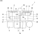
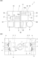
- FIG. 1 to FIG. 4 each schematically show an entire configuration of a range extender for a BEV, with some part thereof being omitted.
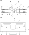
- FIG. 5 shows schematically shows an configuration of part of an engine dedicated for power generation of the range extender for a BEV
- FIG. 6 to FIG. 8 each show a valvetrain of the engine dedicated for power generation of the range extender for a BEV.
- a BEV range extender (1) includes: an engine dedicated for power generation (2); a generator (3) that generates power by driving of the engine dedicated for power generation (2); a fuel tank (4) of the engine dedicated for power generation (2); a cooling system (5) of the engine dedicated for power generation (2); and a mount (not shown) to be used when the BEV range extender (1) is mounted on a vehicle.
- the BEV range extender (1) includes electrical equipment necessary for power generation, such as an inverter.
- the engine dedicated for power generation (2) is a horizontally opposed engine, and includes: a crankshaft (11) having a horizontal rotation center axis extending in the front-back direction; an even number of (two, in this embodiment) cylinders (12) in total that are arranged on both left and right sides of the crankshaft (11) such that the cylinders (12) respectively provided in equal number on the both sides are opposed to each other with the crankshaft interposed therebetween; pistons (13) that arranged on both of the left and right sides of the crankshaft (11) and provided within respective cylinders (12) such that the pistons (13) on both sides are opposed to each other with the crankshaft interposed therebetween; and an intake manifold (14).
- the cylinders (12) are arranged on both left and right sides of the crankshaft (11) in equal number, with the longitudinal direction of the cylinders (12) arranged on the left and right sides being directed in the left-right direction.
- the engine dedicated for power generation (2) includes: two left and right cylinder blocks (15) arranged on both left and right sides of the crankshaft (11); and two left and right cylinder heads (16) each provided to the corresponding cylinder block (15), and the crankshaft (11) is rotatably supported on both cylinder blocks (15) with the crankshaft (11) sandwiched by both cylinder blocks (15).
- the two left and right pistons (13) are connected to the crankshaft (11) via respective conrods (13a), and reciprocation motion of both pistons (13) causes the crankshaft (11) to rotate around the rotation center axis.
- the cylinder blocks (15) and the cylinder heads (16) are separately formed to be mutually fixed in some cases, while the cylinder blocks (15) and the cylinder heads (16) are integrally formed in other cases.
- Each of the cylinder blocks (15) of the engine dedicated for power generation (2) is provided with one cylinder (12), and each of the cylinder heads (16) is provided with: one combustion chamber (17) corresponding to a cylinder (12); and two intake ports (18) and two exhaust ports (19) both facing the combustion chamber (17).
- Both intake ports (18) of each cylinder head (16) are opened and closed respectively by intake valves (21), and both exhaust ports (19) are opened and closed respectively by exhaust valves (22).
- the two intake ports (18) are formed, adjacently in the front-back direction, at an upper portion of the combustion chamber (17), while the two intake valves (21) that open and close both intake ports (18) are arranged adjacently in the front-back direction.
- the two exhaust ports (19) are formed, adjacently in the front-back direction, at a lower portion of the combustion chamber (17), while the two exhaust valves (22) are arranged adjacently in the front-back direction.
- the two intake valves (21) are arranged above the two exhaust valves (22). That is, the engine dedicated for power generation (2) includes: two cylinders (12) and two combustion chambers (17), four intake ports (18) and four exhaust ports (19), and four intake valves (21) and four exhaust valves (22).
- the valvetrain (23) is composed of: a first valvetrain unit (24) that actuates all the intake valves (21) that open and close both intake ports (18) facing the left and right combustion chambers (17); and a second valvetrain unit (25) that actuates all the exhaust valves (22) that open and close both exhaust ports (19) facing the left and right combustion chambers (17).
- the first valvetrain unit (24) is disposed at a height position above the cylinders (12), preferably immediately above the crankshaft (11), and includes: a first camshaft (26) configured to be rotated around a horizontal rotation center axis by the crankshaft (11); four first pushrods (28) in total, that is, two of them on the right side and two of them on the left side, respectively, configured such that each two of the first pushrods (28) are provided
- the first camshaft (26) is disposed immediately above the crankshaft (11) and at a height position above both of the cylinders (12).
- the second valvetrain unit (25) is disposed at a height position below the cylinders (12), preferably immediately below the crankshaft (11), and includes: a second camshaft (31) configured to be rotated around a horizontal rotation center axis by the crankshaft (11); four second pushrods (33) in total, that is, two of them on the right side and the two of them on the left side, respectively, configured such that each two of the second pushrods (33) are provided for each cylinder (12) and all the second pushrods (33) are driven by two second cams (32) attached to the second camshaft (31); and four second rocker arms (31) in total, that is, two of them on the right side and two of them on the left side, respectively, configured such that each two of the second rocker arms (31) are provided for each cylinder (12) and all the second rocker arms (31) are driven by the second pushrods (33
- the number of the intake ports and the intake valve and the number of the exhaust ports and the exhaust valves are not limited to two.
- the valvetrain configured to actuate the intake valves and the exhaust valves are not limited to those described above, and those of publicly-known SOHC (single overhead cam) system, DOHC (double overhead cam) system, and OHV (overhead valve) system may be used.
- the generator (3) is disposed at an approximately center portion in the length direction of the engine dedicated for power generation (2) such that the engine dedicated for power generation (2) and the generator (3) are T-shaped in planar view.
- the rotating shaft (3a) of the generator (3) is disposed horizontally, and is disposed coaxially with the crankshaft (11) or disposed on an axis parallel to the crankshaft (11).
- the rotating shaft (3a) is connected to the crankshaft (11) via the power transmission device (35), and rotation of the crankshaft (11) causes the rotating shaft (3a) to be rotated with acceleration or deceleration.
- the fuel tank (4) is disposed such that the entirety of the fuel tank (4) is accommodated within at least either one of two spaces (36), (37) (within the right space (36), in this embodiment) surrounded by: vertical planes where both ends, in a longitudinal direction, of the engine dedicated for power generation (2) are located; and a vertical plane where a distal end, of the generator (3), projecting from the engine dedicated for power generation (2) is located.
- the installation location of the fuel tank (4) is not limited thereto, and may be modified appropriately.
- the cooling system (5) is disposed such that at least part of the cooling system (5) is accommodated at the side opposite to the right side space (36) where the fuel tank (4) is disposed (accommodated within the left space (37), in this embodiment), out of the two spaces (36), (37) surrounded by: vertical planes where both ends, in a longitudinal direction, of the engine dedicated for power generation (2) are located; and a vertical plane where a distal end, of the generator (3), projecting from the engine dedicated for power generation (2) is located.
- the installation location of the cooling system (5) is not limited thereto, and may be modified appropriately.
- the cooling system (5) may be disposed on the front-side side surface of the engine dedicated for power generation (2) of the BEV range extender (1), the front-side side surface being located opposite to the side on which the generator (3) is disposed, such that the cooling system (5) is disposed parallel to the longitudinal direction of the engine dedicated for power generation (2).
- the intake manifold (14) has: a surge tank (38); and the same number of branch pipes (39) as the cylinders (12).
- the surge tank (38) of the intake manifold (14) is disposed along an area: from a front-side side surface of the engine dedicated for power generation (2), the front-side side surface being located opposite to the side on which the generator (3) is disposed; to a portion at the front side on the top surface of the engine dedicated for power generation (2).
- the branch pipes (39) extend in the left-right direction from the surge tank (38) so as be in communication with the surge tank (38), and the distal end portion of each branch pipe (39) is connected to the top surface of the corresponding cylinder head (16) of the engine dedicated for power generation (2).
- the branch pipe (39) at the left side is configured to send intake air within the surge tank (38) into the intake ports (21) facing the combustion chamber (17) at the left side
- the branch pipe (39) at the right side is configured to send intake air within the surge tank (38) into the intake ports (21) facing the combustion chamber (17) at the right side.
- the above-described BEV range extender (1) is installed at various locations of the BEV.
- the BEV range extender (1) is disposed at the lower portion of the engine compartment or below the truck bed.
- the BEV range extender (1) is disposed below the van body.
- the BEV range extender (1) is disposed at the lower portion of the engine compartment or below the trunk.
- the BEV range extender (1) is disposed at the lower portion of the engine compartment or below the luggage compartment.
- vehicle range extender (1) is not limited to the one that is shown, and as long as the necessary space is secured, it is possible to install the vehicle range extender (1) at any location.
- the engine dedicated for power generation (2) is driven, and power is generated by the generator (3), whereby generated power is supplied to the battery for driving the BEV.
- the BEV driving range is extended.
- the surge tank (38) of the intake manifold (14) is disposed along an area: from the front-side side surface of the engine dedicated for power generation (2), the front-side side surface being located opposite to the side on which the generator (3) is disposed; to a portion at the front side on the top surface of the engine dedicated for power generation (2), but the configuration of the surge tank (38) is not limited thereto.
- the engine dedicated for power generation (2) may include an intake manifold (40) consisting of: a surge tank (41) disposed along the front-side side surface of the engine dedicated for power generation (2); and left and right branch pipes (42) which extend in the left-right direction from the surge tank (41), and each of the distal end portion of which is connected to the front-side side surface of the corresponding cylinder head (16) of the engine dedicated for power generation (2).
- the branch pipe (42) at the left side is configured to send intake air to the intake ports (21) facing the combustion chamber (17) at the left side
- the branch pipe (42) at the right side is configured to send intake air to the intake ports (21) facing the combustion chamber (17) at the right side.
- the engine dedicated for power generation (2) is a horizontally opposed engine having two cylinders (12), but is not limited thereto, and may be a horizontally opposed engine including four cylinders or a horizontally opposed engine including six cylinders.
- the distal end of each branch pipe of the intake manifold to be used in the engine dedicated for power generation is connected to the top surface of the cylinder head (16).
- cylinders on both sides of the crankshaft (11) are formed in one cylinder block, while the cylinder block is provided with one cylinder head, and the cylinder head is provided with: a combustion chamber corresponding to each of the cylinders; and two intake ports and two exhaust ports facing the combustion chamber.
Landscapes
- Engineering & Computer Science (AREA)
- Mechanical Engineering (AREA)
- General Engineering & Computer Science (AREA)
- Chemical & Material Sciences (AREA)
- Combustion & Propulsion (AREA)
- Hybrid Electric Vehicles (AREA)
- Control Of Vehicle Engines Or Engines For Specific Uses (AREA)
- Arrangement Or Mounting Of Propulsion Units For Vehicles (AREA)
Applications Claiming Priority (3)
| Application Number | Priority Date | Filing Date | Title |
|---|---|---|---|
| JP2023099866 | 2023-06-19 | ||
| JP2023142229A JP7488539B1 (ja) | 2023-06-19 | 2023-09-01 | バッテリー電気自動車用レンジエクステンダ |
| PCT/JP2024/018587 WO2024262218A1 (ja) | 2023-06-19 | 2024-05-21 | バッテリー電気自動車用レンジエクステンダ |
Publications (2)
| Publication Number | Publication Date |
|---|---|
| EP4528087A1 true EP4528087A1 (de) | 2025-03-26 |
| EP4528087A4 EP4528087A4 (de) | 2026-02-25 |
Family
ID=91082766
Family Applications (1)
| Application Number | Title | Priority Date | Filing Date |
|---|---|---|---|
| EP24821731.7A Pending EP4528087A4 (de) | 2023-06-19 | 2024-05-21 | Bereichserweiterer für ein batterieelektrofahrzeug |
Country Status (4)
| Country | Link |
|---|---|
| EP (1) | EP4528087A4 (de) |
| JP (1) | JP7488539B1 (de) |
| CN (1) | CN119497786A (de) |
| WO (1) | WO2024262218A1 (de) |
Families Citing this family (1)
| Publication number | Priority date | Publication date | Assignee | Title |
|---|---|---|---|---|
| JP7846941B1 (ja) * | 2026-01-06 | 2026-04-16 | 株式会社レンジE設計 | 発電専用エンジン |
Family Cites Families (12)
| Publication number | Priority date | Publication date | Assignee | Title |
|---|---|---|---|---|
| JPS59148443U (ja) * | 1983-03-24 | 1984-10-04 | ダイハツ工業株式会社 | 過給式水平対向型内燃機関 |
| JP5486974B2 (ja) | 2010-03-19 | 2014-05-07 | 本田技研工業株式会社 | ハイブリッド車両 |
| JP2012225298A (ja) | 2011-04-21 | 2012-11-15 | Nissan Motor Co Ltd | 往復動エンジンの動弁機構 |
| ITMO20130030A1 (it) * | 2013-02-11 | 2014-08-12 | Robby Moto Engineering S R L | Apparecchiatura di alimentazione elettrica supplementare, impiegabile in particolare in veicoli elettrici o simili |
| JP6521429B2 (ja) | 2015-03-20 | 2019-05-29 | 株式会社Subaru | 車両のパワートレイン構造 |
| JP6215888B2 (ja) | 2015-09-30 | 2017-10-18 | 本田技研工業株式会社 | ハイブリッド式パワーユニット |
| CN105257404A (zh) * | 2015-11-24 | 2016-01-20 | 白云龙 | 水平对置增程器 |
| CN207892692U (zh) * | 2017-12-12 | 2018-09-21 | 山东飞奥航空发动机有限公司 | 水冷水平对置双缸起电一体机 |
| DE102020112747B4 (de) * | 2020-05-12 | 2024-06-06 | Audi Aktiengesellschaft | Range-Extender, aufweisend eine Verbrennungskraftmaschine und eine elektrische Maschine, sowie ein Kraftfahrzeug |
| JP7547934B2 (ja) | 2020-10-29 | 2024-09-10 | スズキ株式会社 | レンジエクステンダ車両用発電ユニットの構造 |
| JP7327358B2 (ja) | 2020-11-12 | 2023-08-16 | トヨタ自動車株式会社 | ハイブリッド車両のエンジン失火検出装置 |
| JPWO2023119354A1 (de) * | 2021-12-20 | 2023-06-29 |
-
2023
- 2023-09-01 JP JP2023142229A patent/JP7488539B1/ja active Active
-
2024
- 2024-05-21 WO PCT/JP2024/018587 patent/WO2024262218A1/ja not_active Ceased
- 2024-05-21 CN CN202480003097.3A patent/CN119497786A/zh active Pending
- 2024-05-21 EP EP24821731.7A patent/EP4528087A4/de active Pending
Also Published As
| Publication number | Publication date |
|---|---|
| EP4528087A4 (de) | 2026-02-25 |
| WO2024262218A1 (ja) | 2024-12-26 |
| CN119497786A (zh) | 2025-02-21 |
| JP2025000527A (ja) | 2025-01-07 |
| JP7488539B1 (ja) | 2024-05-22 |
Similar Documents
| Publication | Publication Date | Title |
|---|---|---|
| US5908077A (en) | Environmentally sensitive hybrid vehicle | |
| EP0745500A1 (de) | Anordnung eines antriebsstranges für ein fahrzeug | |
| EP4528087A1 (de) | Bereichserweiterer für ein batterieelektrofahrzeug | |
| US4121558A (en) | Internal combustion engine assembly | |
| JPS60230503A (ja) | 自動車用v型エンジン | |
| JP6583368B2 (ja) | 車両用パワートレインユニット | |
| WO2019039217A1 (ja) | 車両用パワートレインユニット | |
| US7114480B2 (en) | V-type engine | |
| US8919484B2 (en) | Drive arrangement for automobile | |
| JP7846941B1 (ja) | 発電専用エンジン | |
| JP2009180210A (ja) | 内燃機関およびこれを搭載した車両 | |
| CN2580121Y (zh) | 一种微型车后轮驱动用汽油发动机 | |
| US20230096904A1 (en) | Two-Cylinder Reciprocating Engine | |
| CN223904878U (zh) | 全地形车 | |
| JP4448292B2 (ja) | V型エンジン | |
| JPH0117623Y2 (de) | ||
| CN213360952U (zh) | 一种具有减振机构的中置纵向发动机 | |
| EP0921958B1 (de) | Bus mit quer eingebauter heckantriebseinrichtung | |
| JP4071512B2 (ja) | 車両用v型エンジン | |
| JP3073334B2 (ja) | 車両の駆動装置 | |
| WO2023119553A1 (ja) | ハイブリッド車両 | |
| KR19980041975U (ko) | 자동차의 브이식스 엔진 배기 매니폴드 | |
| BR102023001163A2 (pt) | Dispositivo de válvula | |
| JP2024179771A (ja) | ハイブリッド車両 | |
| JPH08156609A (ja) | 車両に対する内燃機関のレイアウト |
Legal Events
| Date | Code | Title | Description |
|---|---|---|---|
| STAA | Information on the status of an ep patent application or granted ep patent |
Free format text: STATUS: UNKNOWN |
|
| STAA | Information on the status of an ep patent application or granted ep patent |
Free format text: STATUS: THE INTERNATIONAL PUBLICATION HAS BEEN MADE |
|
| PUAI | Public reference made under article 153(3) epc to a published international application that has entered the european phase |
Free format text: ORIGINAL CODE: 0009012 |
|
| STAA | Information on the status of an ep patent application or granted ep patent |
Free format text: STATUS: REQUEST FOR EXAMINATION WAS MADE |
|
| 17P | Request for examination filed |
Effective date: 20241220 |
|
| AK | Designated contracting states |
Kind code of ref document: A1 Designated state(s): AL AT BE BG CH CY CZ DE DK EE ES FI FR GB GR HR HU IE IS IT LI LT LU LV MC ME MK MT NL NO PL PT RO RS SE SI SK SM TR |
|
| A4 | Supplementary search report drawn up and despatched |
Effective date: 20260122 |
|
| RIC1 | Information provided on ipc code assigned before grant |
Ipc: F02B 75/24 20060101AFI20260116BHEP Ipc: B60K 6/40 20071001ALI20260116BHEP Ipc: B60K 6/46 20071001ALI20260116BHEP Ipc: F01L 1/02 20060101ALI20260116BHEP Ipc: F01L 1/12 20060101ALI20260116BHEP Ipc: F02B 63/04 20060101ALI20260116BHEP Ipc: F02D 29/06 20060101ALI20260116BHEP Ipc: F02M 35/10 20060101ALI20260116BHEP Ipc: F02M 35/104 20060101ALI20260116BHEP Ipc: F01L 1/14 20060101ALI20260116BHEP Ipc: B60K 6/24 20071001ALI20260116BHEP Ipc: F01L 1/18 20060101ALI20260116BHEP Ipc: F01L 1/42 20060101ALI20260116BHEP |