EP4528014A1 - Heizvorrichtung für eine kleidungspflegevorrichtung - Google Patents
Heizvorrichtung für eine kleidungspflegevorrichtung Download PDFInfo
- Publication number
- EP4528014A1 EP4528014A1 EP22942824.8A EP22942824A EP4528014A1 EP 4528014 A1 EP4528014 A1 EP 4528014A1 EP 22942824 A EP22942824 A EP 22942824A EP 4528014 A1 EP4528014 A1 EP 4528014A1
- Authority
- EP
- European Patent Office
- Prior art keywords
- water
- heating
- heat
- electrode layer
- heating device
- Prior art date
- Legal status (The legal status is an assumption and is not a legal conclusion. Google has not performed a legal analysis and makes no representation as to the accuracy of the status listed.)
- Pending
Links
Images



Classifications
-
- D—TEXTILES; PAPER
- D06—TREATMENT OF TEXTILES OR THE LIKE; LAUNDERING; FLEXIBLE MATERIALS NOT OTHERWISE PROVIDED FOR
- D06F—LAUNDERING, DRYING, IRONING, PRESSING OR FOLDING TEXTILE ARTICLES
- D06F39/00—Details of washing machines not specific to a single type of machines covered by groups D06F9/00 - D06F27/00
- D06F39/04—Heating arrangements
-
- D—TEXTILES; PAPER
- D06—TREATMENT OF TEXTILES OR THE LIKE; LAUNDERING; FLEXIBLE MATERIALS NOT OTHERWISE PROVIDED FOR
- D06F—LAUNDERING, DRYING, IRONING, PRESSING OR FOLDING TEXTILE ARTICLES
- D06F34/00—Details of control systems for washing machines, washer-dryers or laundry dryers
- D06F34/14—Arrangements for detecting or measuring specific parameters
- D06F34/22—Condition of the washing liquid, e.g. turbidity
-
- F—MECHANICAL ENGINEERING; LIGHTING; HEATING; WEAPONS; BLASTING
- F22—STEAM GENERATION
- F22B—METHODS OF STEAM GENERATION; STEAM BOILERS
- F22B1/00—Methods of steam generation characterised by form of heating method
- F22B1/28—Methods of steam generation characterised by form of heating method in boilers heated electrically
- F22B1/284—Methods of steam generation characterised by form of heating method in boilers heated electrically with water in reservoirs
-
- D—TEXTILES; PAPER
- D06—TREATMENT OF TEXTILES OR THE LIKE; LAUNDERING; FLEXIBLE MATERIALS NOT OTHERWISE PROVIDED FOR
- D06F—LAUNDERING, DRYING, IRONING, PRESSING OR FOLDING TEXTILE ARTICLES
- D06F2103/00—Parameters monitored or detected for the control of domestic laundry washing machines, washer-dryers or laundry dryers
- D06F2103/18—Washing liquid level
-
- D—TEXTILES; PAPER
- D06—TREATMENT OF TEXTILES OR THE LIKE; LAUNDERING; FLEXIBLE MATERIALS NOT OTHERWISE PROVIDED FOR
- D06F—LAUNDERING, DRYING, IRONING, PRESSING OR FOLDING TEXTILE ARTICLES
- D06F39/00—Details of washing machines not specific to a single type of machines covered by groups D06F9/00 - D06F27/00
- D06F39/08—Liquid supply or discharge arrangements
- D06F39/087—Water level measuring or regulating devices
-
- F—MECHANICAL ENGINEERING; LIGHTING; HEATING; WEAPONS; BLASTING
- F22—STEAM GENERATION
- F22B—METHODS OF STEAM GENERATION; STEAM BOILERS
- F22B1/00—Methods of steam generation characterised by form of heating method
- F22B1/28—Methods of steam generation characterised by form of heating method in boilers heated electrically
- F22B1/30—Electrode boilers
Definitions
- the present invention relates to a heating device for a garment care device, and more particularly, to a heating device applied to a garment care device such as a washing machine or a refresher so as to instantly heat water.
- a garment care device includes a washing machine, a dryer, a refresher, and the like.
- the washing machine may be largely divided into a pulsator washing machine for performing washing by a water flow generated as a pulsator having a plate shape rotates, and a drum washing machine for performing washing by using a height difference and a frictional force between laundry and washing water supplied into a drum as the drum that is laid down rotates.
- the drum washing machine has advantages that the laundry is less tangled and washing water and detergent are less required during a washing operation, so that a demand for the drum washing machine is rapidly increasing.
- the drum washing machine may have a water storage tank (tub) installed in an inner space of a cabinet that forms an exterior of the drum washing machine, and a washing tank (drum) may be rotatably installed in the tub.
- a drum washing machine in which a heater for heating washing water to turn the washing water into hot water is installed on a bottom surface of a water storage tank so that the hot water may be generated in the washing machine itself is also being released. Therefore, even when cold water is introduced into the water storage tank, the heater may operate to heat the cold water to a temperature that is appropriate for washing, so that there is no need to connect the drum washing machine to a separate water faucet for supplying hot water.
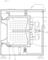
- a drum washing machine may include: a cabinet 1 forming an accommodation space therein; a water storage tank 2 (tub) installed in the cabinet 1; a washing tank 3 (drum) rotatably arranged in the water storage tank 2; a heating device 4 (heater) installed between the water storage tank 2 and the washing tank 3; and a driving motor 5 for rotating the washing tank 3.
- the drum washing machine may include: a water supply port and a detergent supply port, which are provided in an upper portion of the cabinet 1; and a drain port provided in a lower portion of the cabinet 1.
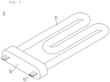
- the heating device 4 may be configured as a sheath heater applied to a conventional drum washing machine so as to boil water or generate steam for boiling washing, steam washing, or sterilization.
- the heating device 4 may include: a heat-generating unit 11 for generating heat; a bracket 12 for fixing one end of the heat-generating unit 11, and installing the heating device 4 in the water storage tank 2 of the drum washing machine; and an electrode terminal 13 penetrating through the bracket 12 so as to be connected to an end portion of the heat-generating unit 11 to supply electricity.
- a heating wire (not shown) having a coil shape may be provided in the heat-generating unit 11, and the heating wire may be connected to the electrode terminal 13 by a medium of a temperature fuse (not shown) for preventing overheating.
- the washing machine having the above configuration may be operated such that cold water is supplied into the water storage tank 2 to fill the water storage tank 2, and the heating device 4 is driven to heat the cold water after the water storage tank 2 is filled with the cold water with an amount that allows washing. Then, after the cold water is heated to a predetermined temperature, the washing machine may be driven to perform the washing.
- tap water (water supply) supplied into the water storage tank may include a lime component (water with such a component is referred to as "hard water"), and the lime component included in the tap water may be attached to a high-temperature heater surface so as to form a lime layer due to heat generated when a heater boils the water.
- the lime layer generated from the hard water may block direct contact between the heat-generating unit and the water so as to overheat the heat-generating unit, so that the heat-generating unit may be damaged, or a lifespan of the heater may be shortened.
- a conventional heater applied to the drum washing machine may be driven after the water storage tank is completely filled with the water, that is, after supply of washing water is completed. Therefore, a long time may be required from a time at which the supply of the washing water starts to a time at which a washing operation is performed after the water is heated.
- the present invention has been proposed to solve the problems described above, and an object of the present invention is to provide a heating device for a garment care device, capable of solve problems of malfunctioning and a shortened lifespan caused by a lime layer formed under a hard water condition.
- an object of the present invention is to provide a heating device for a garment care device, capable of shortening a time from a time at which supply of washing water starts to a time at which washing is performed after the washing water is heated.
- an object of the present invention is to provide a heating device for a garment care device, capable of improving accuracy of detection of a water level for water supplied into a water supply tank.
- a heating device for a garment care device which is a device installed in a water storage tank in the garment care device so as to heat water, includes: a heating plate, which is a plate having a predetermined thickness, and forms a heating surface on an outer surface of the heating plate; a heat-generating electrode layer formed on an inner surface of the heating plate while providing a pair of first electrode pads; a pair of first lead electrodes, each having one end portion connected to the first electrode pad so as to supply power to the heat-generating electrode layer; a housing for accommodating and protecting the heating plate so that the heating surface is exposed; and a bracket coupled to a side portion of the housing so as to fixedly expose an opposite end portion of the first lead electrode to an outside, wherein the heat-generating electrode layer includes electrode lines in a series or parallel structure, in which a gap (P) that is greater than or equal to 1/3 of a width (W) is ensured between the electrode lines adjacent to each other.
- P a gap
- W width
- the heating device may further include: a water level detection sensor installed in the housing so as to detect a water level in the water storage tank, and the water level detection sensor may be driven when immersed in the water filling the water storage tank so as to heat the water.
- the housing may form a water channel having a concave shape along a top surface edge of the housing, and the water level detection sensor may be installed in the water channel so as to detect the water level of the water introduced into the water channel.
- the water channel may be configured such that a blocking wall is formed at an outer end portion of the water channel so as to isolate the water channel from an outer region, and the water is introduced into or discharged from the water channel through a through-hole formed in the blocking wall.
- the heating device may further include: a resistance electrode layer formed on the inner surface of the heating plate in a region that does not overlap the heat-generating electrode layer while providing a pair of second electrode pads; and a pair of second lead electrodes, each having one end portion connected to the second electrode pad so as to supply power to the resistance electrode layer.
- the heating surface may be formed by bending a central region of the heating plate so that the bent central region is concave inward.
- the heating surface may have an inclined structure with different bending depths.
- a width and a gap of a heat-generating electrode layer may be adjusted, so that problems of malfunctioning, damage, and a shortened lifespan caused by a lime layer can be reduced.
- a water level of washing water may be detected so as to heat the washing water from a time point at which filled of the washing water is performed to a predetermined extent, so that a time required for an entire washing operation can be shortened.
- influence of waves generated during a process of supplying washing water into a water storage tank may be blocked, so that accuracy of detection of a water level can be greatly improved.
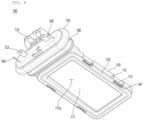
- FIGS. 3 and 4 are views showing a heating device for a drum washing machine according to the present embodiment when viewed from a top and a bottom
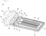
- FIG. 5 is a view showing an internal structure of the heating device of FIG. 3
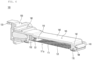
- FIGS. 6 and 7 are views showing sections of the heating device of FIG. 3 taken in an A-A direction and a B-B direction
- FIG. 8 is a view showing a structure of a heat-generating electrode layer of the heating device of FIG. 3
- FIG. 9 is a view showing a state in which the heating device of FIG. 3 is immersed in washing water.
- a heating device 100 may include: a heating plate 110 for generating heat; a heat-generating electrode layer 120 formed on one surface (top surface) of the heating plate; a resistance electrode layer 130 formed on the top surface of the heating plate 110, which does not overlap the heat-generating electrode layer 120; a housing 140 for accommodating and protecting the heating plate 110; a bracket 150 for installing the heating device 100 to a water storage tank 2 of a washing machine; and a water level detection sensor 160 installed in the housing.
- the heating device 100 may further include: a first sealing member 170 interposed between the heating plate 110 and the housing 140; and a second sealing member 180 interposed between the housing 140 and the bracket 150.
- the heating device 100 may be configured such that, when power is supplied through a pair of first lead electrodes 122, a current may flow through the heat-generating electrode layer 120 so as to generate high-temperature heat in the heat-generating electrode layer 120, and the generated heat may be released through the heating plate 110 so as to heat water making contact with a surface of the heating plate 110.
- the heating plate 110 may be formed of a material having insulating properties and excellent thermal conductivity.
- the heating plate 110 may be configured as a plate having a predetermined thickness, and may have a central region that is concavely bent, in which a concave surface (bottom surface) may form a heating surface 111 for heating water making contact with the heating surface 111.
- the heating plate 110 may be configured as a rectangular plate formed of a SUS material, and may have a central region that is concavely bent in a rectangular shape, in which a concave groove formed by the bending may provide the heating surface 111.
- the heating plate 110 may have a temperature difference between the central region in which the electrode layer is formed and an edge region in which the electrode layer is not formed, and the plate may be bent or twisted by the temperature difference so as to be deformed in shape. Since thermal deformation of the heating plate 110 caused by the temperature difference is more significant as a thickness of the plate becomes thinner, there is a limitation in making a thickness of the heating plate 110 having a simple plate shape thinner to prevent the thermal deformation. Therefore, when the heating plate 110 has a sufficient thickness so that the thermal deformation may not occur, the heating plate 110 may have a simple plate shape. However, in this case, since the heating plate 110 has to have a predetermined thickness or more, a weight of the heating device may be increased, and a manufacturing cost may be increased due to a material cost.
- both side surfaces of the heating surface 111 may function as reinforcing ribs, so that the thickness of the heating plate 110 may become thinner while preventing the thermal deformation.
- the heating plate 110 may have a thin thickness of 0.6 mm or less.
- the heating plate 110 may be configured such that the heating surface 111 having the concave shape has an inclined structure.
- a heating space 111a formed in a lower portion of the heating plate 110 by the concave groove may be formed relatively deep on one side and formed shallower toward an opposite side.
- the heating device 100 may operate while be immersed in the water in the washing machine, and contaminated washing water may be discharged after the washing is completed.
- the concave heating surface 111 since the washing water has to be prevented from remaining on the heating surface 111 of the concave groove, the concave heating surface 111 may be preferably installed to face downward. Therefore, a surface (bottom surface) of the heating plate 110 may form the heating surface 111 having a shape of a groove that is concave upward, and the heating space 111a may be formed under the heating surface 111.
- an air pocket may be formed in the concave heating space 111a.
- the air pocket may be formed in an entire region of the heating surface 111, so that the water may not make contact with the heating surface 111 due to the air pocket even when the water storage tank 2 is filled with the water, and thus the heating plate 110 may be overheated so as to be damaged.
- the heating surface 111 has an inclined structure as in the present embodiment, the air pocket may be formed only in a partial space at an uppermost portion of the heating space 111a, so that a space in which the air pocket may be formed may be minimized, and thus the heating plate 110 may be prevented from being overheated and damaged by the air pocket.
- the heating plate 110 may be finished such that an edge end portion may be bent or curled to one side so as to form a reinforcing flange 112.
- the reinforcing flange 112 may prevent deformation of the heating plate 110.
- the reinforcing flange 112 may preferably have a lower height than the heating surface 111 so as not to interfere with a process of forming the heat-generating electrode layer 120 on the heating surface 111.
- a fastening device such as a screw may be used, or the coupling may be performed by using a structure of the heating plate 110 and the housing 140.
- a plurality of fastening holes 113 may be further formed in the reinforcing flange 112 of the heating plate 110, and a plurality of fastening protrusions 141 having a hook structure may be formed in the housing 140 at positions corresponding to the fastening holes 113.
- the heat-generating electrode layer 120 may be formed by printing conductive heat-generating paste having a predetermined resistance on the surface of the heating plate 110, and may be formed on the surface (top surface) of the heating plate 110, which is opposite to the heating surface 111 as shown in the drawings.
- the heat-generating electrode layer 120 may have a band shape having a predetermined width and a predetermined length, and may have both end portions that provide a pair of first electrode pads 121 with which the first lead electrodes 122 make contact.
- the heat-generating electrode layer 120 may be configured as electrode lines having a series structure or a parallel structure between the pair of first electrode pads 121.
- the electrode lines constituting the heat-generating electrode layer 120 may have a predetermined width W and a predetermined gap P.
- the heat generated from the heat-generating electrode layer 120 may be transferred to the heating plate 110, and the water making contact with the heating plate 110 may be heated.
- a lime layer 120' may be formed on an opposite surface (i.e., the heating surface) of the heating plate 110 in which the heat-generating electrode layer 120 is formed so as to correspond to a position in which the heat-generating electrode layer 120 is formed.
- the lime layer 120' formed on the heating surface 111 may gradually grow based on the electrode lines of the heat-generating electrode layer 120. As the lime layer 120' grows, the lime layer 120' may be connected to a lime layer 120' adjacent thereto, and in this case, the heating surface 111 may be covered by the lime layer 120', and the heat transferred from the heat-generating electrode layer 120 may be not be rapidly released, which may eventually cause the heating device 100 to malfunction or to be damaged.
- the heat-generating electrode layer 120 may have a predetermined width W and a predetermined gap P, and according to the present embodiment, the heat-generating electrode layer 120 may have a gap P that is greater than or equal to at least 1/3 of the width W (P ⁇ 1/3W).
- the heat-generating electrode layer 120 may preferably have a width W that is as wide as possible and a gap P that is as narrow as possible.
- the gap P that is greater than or equal to at least 1/3 of the width W has to be ensured between the electrode lines adjacent to each other and constituting the heat-generating electrode layer 120.
- the first lead electrode 122 may be configured to supply power to the heat-generating electrode layer 120, and a pair of conductive metal wires may be used as the first lead electrodes 122. One end portion of the first lead electrode 122 may be connected to the first electrode pad 121, and an opposite end portion of the first lead electrode 122 may penetrate through the bracket 150 so as to be exposed to an outside so as to form a first lead terminal 123.
- the resistance electrode layer 130 may be formed by printing conductive heat-generating paste having a predetermined resistance on the surface of the heating plate 110 in a region in which the heat-generating electrode layer 120 is not formed.
- the resistance electrode layer 130 may have a band shape having a predetermined width and a predetermined length, and may have both end portions that provide a pair of second electrode pads 131 with which the second lead electrodes 132 make contact.
- the resistance electrode layer 130 may measure a resistance of the heat-generating electrode layer 120 according to a temperature so that a temperature of the heated water may be predicted. Since the resistance generally varies according to the temperature, the resistance of the heat-generating electrode layer 120, which varies according to a temperature of the heating plate 110, may be measured through the resistance electrode layer 130 so that the power supplied to the heat-generating electrode layer 120 may be controlled so as to allow the heating plate 110 that heats the water to be heated to a constant temperature.
- the resistance electrode layer 130 may be formed by printing the conductive paste, which is the same material as the heat-generating electrode layer 120. In addition, the resistance electrode layer 130 may be connected to an external resistance measurement module through the second lead electrode 132.
- the resistance electrode layer 130 may be used to measure the resistance of the heat-generating electrode layer 120 so as to predict the temperature of the water, the resistance electrode layer 130 may also function as another heat-generating electrode layer that heats the heating plate 110.
- the heating device 100 may also be used to apply heat to the heating plate 110 in a localized region, as needed.
- the resistance electrode layer 130 since the resistance electrode layer 130 is formed of the conductive paste, which is the same material as the heat-generating electrode layer 120, and has a relatively narrow area, power may be applied to the resistance electrode layer 130 to heat the heating plate 110 in the localized region. Therefore, the resistance electrode layer 130 may be selectively connected to an external resistance measurement module or an external power supply module through the second lead electrode 132.
- the second lead electrode 132 may be configured to supply power to the resistance electrode layer 130, and a pair of conductive metal wires may be used as the second lead electrodes 132. One end portion of the second lead electrode 132 may make contact with the second electrode pad 131, and an opposite end portion of the second lead electrode 132 may penetrate through the bracket 150 so as to be exposed to the outside so as to form a second lead terminal 133.
- the housing 140 may be configured to accommodate the heating plate 110, the first lead electrode 122, and the second lead electrode 132, and to insulate and protect the heating plate 110, the first lead electrode 122, and the second lead electrode 132 from the outside, and may be formed of a nonconductive material with a high heat resistance.
- the housing 140 may form a sufficient space therein to accommodate the heating plate 110, and the heating plate 110 may be coupled to a lower portion of the housing 140. In this case, the heating surface 111 that is concavely bent may be exposed to a lower space while being hidden in an inner space of the housing 140.
- the housing 140 may form a water channel 142 having a concave groove shape along a top surface edge of the housing 140.
- the water channel 142 may be isolated from the outside through a blocking wall 143 formed at an outer end portion of the water channel 142, and may be connected to the outside through a through-hole 144 formed on a front side of the housing 140. Therefore, when the water storage tank 2 is filled with the water while the heating device 100 is installed in the washing machine, the water may fill the water channel 142 through the through-hole 144, and upon drainage after the washing is finished, the water filling the water channel 142 may be drained again through the through-hole 144.
- the water level detection sensor 160 may be installed in the water channel 142 so as to detect a water level of the water filling the water storage tank 2.
- the housing 140 may have an avoidance groove 145 having a top surface formed in a concave curved surface shape and configured to avoid a washing tank 3 of the washing machine.
- the avoidance groove 145 may have a curved surface shape corresponding to a circumferential surface of the washing tank 3, and may preferably have a curvature corresponding to the circumferential surface of the washing tank 3.
- a drum washing machine may include a driving motor 5 having a rotation shaft on one side of a cabinet 1, and the washing tank 3 may have one side coupled to the rotation shaft so as to be horizontally arranged.
- the washing tank 3 may also rotate, in which one side (a driving motor side) of the washing tank 3 may be fixed by the rotation shaft so as to rotate, while an opposite side (a door side) of the washing tank 3 may slightly shake so as to rotate in a larger trajectory than an actual radius of the washing tank 3. Therefore, there is a risk that the washing tank 3 may collide with the housing 140 of the heating device 100.
- the heating device 100 may have the avoidance groove 145 formed on the top surface of the housing 140 and having a concave curved surface corresponding to the circumferential surface of the washing tank 3, so that collision or interference between the housing 140 and the washing tank 3 may be prevented when the washing machine is driven.
- the bracket 150 may be coupled to the housing 140 to seal side opening portions of the housing 140 through which the first and second lead electrodes 122 and 132 are exposed while fixing the first and second lead electrodes 122 and 132, and may allow the heating device 100 to be installed in the water storage tank 2.
- the water level detection sensor 160 may be configured to detect the water level of the water filling the water storage tank 2 so that the heating device 100 may be driven.
- the heating device 100 may be driven, that is, the filling of the water has been performed to a water level at which the heating device 100 is immersed in the water, so that the heating device 100 may be driven during a process of filling the water storage tank 2 with the water. Therefore, the heating device 100 may be driven in advance to heat the water before the water storage tank is completely filled with the water in an amount sufficient for washing, so that a time for heating the water to a temperature sufficient for washing may be shortened.
- the water level detection sensor 160 may be configured as a pair of electrode rods in which one end extends into the water channel 142 and an opposite end is exposed out of the bracket 150, and may be configured as various types of sensors capable of detecting a water level.
- the water level detection sensor 160 may be installed in the water channel 142 protected from the outside by the blocking wall 143.
- waves waves
- the water storage tank 2 is filled with the water
- waves w waves
- transmission of the waves is blocked by the blocking wall 143 in the water channel 142, so that the water level may be increased in a constant state, and thus the accuracy of the detection of the water level may be improved.
- the first sealing member 170 may be interposed between the heating plate 110 and the housing 140 to seal a space between the heating plate 110 and the housing 140.
- the second sealing member 180 may be interposed between the housing 140 and the bracket 150 to seal a space between the housing 140 and the bracket 150 while sealing a space between the housing 140 and the water storage tank 2 when the bracket 150 is coupled to the water storage tank 2 so as to prevent leakage of the water filling the water storage tank 2.
- the first and second sealing members 170 and 180 may be formed of a silicone material having a high heat resistance and elasticity.
- the heating device 100 having the above configuration may be fastened such that the housing 140 is located in the water storage tank 2, and the heating device 100 may be driven to heat the water as the heating device 100 starts to be immersed in the water in the water storage tank 2.
- the heating device 100 may generate the heat in a surface region through the heating plate 110 so that the formation of the lime layer caused by the hard water may be minimized, while the heat-generating electrode layer may be formed to have a predetermined gap so that the malfunctioning, the damage, and a shortened lifespan caused by the lime layer may be minimized.
- the heating device may be applied to various types of garment care devices that heat water or generate steam to manage a garment, such as a refresher.
Landscapes
- Engineering & Computer Science (AREA)
- Textile Engineering (AREA)
- Life Sciences & Earth Sciences (AREA)
- Sustainable Development (AREA)
- Sustainable Energy (AREA)
- Physics & Mathematics (AREA)
- Thermal Sciences (AREA)
- Mechanical Engineering (AREA)
- General Engineering & Computer Science (AREA)
- Detail Structures Of Washing Machines And Dryers (AREA)
- Control Of Washing Machine And Dryer (AREA)
Applications Claiming Priority (2)
| Application Number | Priority Date | Filing Date | Title |
|---|---|---|---|
| KR1020220060149A KR102705471B1 (ko) | 2022-05-17 | 2022-05-17 | 의류 관리기용 가열 장치 |
| PCT/KR2022/008000 WO2023224160A1 (ko) | 2022-05-17 | 2022-06-07 | 의류 관리기용 가열 장치 |
Publications (2)
| Publication Number | Publication Date |
|---|---|
| EP4528014A1 true EP4528014A1 (de) | 2025-03-26 |
| EP4528014A4 EP4528014A4 (de) | 2025-11-12 |
Family
ID=88835446
Family Applications (1)
| Application Number | Title | Priority Date | Filing Date |
|---|---|---|---|
| EP22942824.8A Pending EP4528014A4 (de) | 2022-05-17 | 2022-06-07 | Heizvorrichtung für eine kleidungspflegevorrichtung |
Country Status (4)
| Country | Link |
|---|---|
| EP (1) | EP4528014A4 (de) |
| KR (2) | KR102705471B1 (de) |
| CN (1) | CN119156473A (de) |
| WO (1) | WO2023224160A1 (de) |
Family Cites Families (8)
| Publication number | Priority date | Publication date | Assignee | Title |
|---|---|---|---|---|
| JP2001102159A (ja) * | 1999-07-27 | 2001-04-13 | Toto Ltd | 温水加熱用金属ヒータ、これを用いた温水装置、及びこれを備えた衛生洗浄装置 |
| KR100774169B1 (ko) * | 2005-11-17 | 2007-11-07 | 엘지전자 주식회사 | 가열 장치, 그리고 이를 이용한 증기 발생 장치 및 가전제품 |
| DE102007058833A1 (de) * | 2007-11-30 | 2009-06-10 | E.G.O. Elektro-Gerätebau GmbH | Heizeinrichtung für eine Waschmaschine, Waschmaschine mit einer Heizeinrichtung sowie Verfahren zum Betrieb einer Heizeinrichtung |
| ITTO20120598A1 (it) * | 2012-07-06 | 2014-01-07 | Illinois Tool Works | Dispositivo di riscaldamento per elettrodomestici con sensore ottico di livello di liquido |
| KR102214069B1 (ko) * | 2014-09-29 | 2021-02-09 | 엘지전자 주식회사 | 스팀발생장치 및 스팀발생장치가 구비된 의류처리장치 |
| KR102669130B1 (ko) * | 2018-08-09 | 2024-05-23 | 엘지전자 주식회사 | 의류처리장치 |
| CN113526619B (zh) * | 2019-08-06 | 2023-06-20 | 无锡小天鹅电器有限公司 | 电解组件及衣物处理设备 |
| KR20210117214A (ko) * | 2020-03-18 | 2021-09-28 | 엘지전자 주식회사 | 의류처리장치 |
-
2022
- 2022-05-17 KR KR1020220060149A patent/KR102705471B1/ko active Active
- 2022-06-07 EP EP22942824.8A patent/EP4528014A4/de active Pending
- 2022-06-07 WO PCT/KR2022/008000 patent/WO2023224160A1/ko not_active Ceased
- 2022-06-07 CN CN202280096153.3A patent/CN119156473A/zh active Pending
-
2024
- 2024-08-29 KR KR1020240116775A patent/KR20240133957A/ko active Pending
Also Published As
| Publication number | Publication date |
|---|---|
| WO2023224160A1 (ko) | 2023-11-23 |
| KR20240133957A (ko) | 2024-09-05 |
| KR102705471B1 (ko) | 2024-09-11 |
| CN119156473A (zh) | 2024-12-17 |
| EP4528014A4 (de) | 2025-11-12 |
| KR20230160543A (ko) | 2023-11-24 |
Similar Documents
| Publication | Publication Date | Title |
|---|---|---|
| KR100753506B1 (ko) | 세탁기용 증기발생장치의 수위감지센서 | |
| KR101253126B1 (ko) | 드럼세탁기 스팀발생기의 수위센서 | |
| CN101055070B (zh) | 蒸汽发生器及具有该蒸汽发生器的滚筒式洗衣机 | |
| RU2480544C2 (ru) | Стиральная машина, в частности стиральная или стирально-сушильная машина для белья, или посудомоечная машина, способ определения погруженного или выступающего состояния электрического сопротивления, используемого в стиральной машине, способ удаления известковых отложений с электрического сопротивления | |
| US9074311B2 (en) | Steam generator and washing machine having the same | |
| EP4528014A1 (de) | Heizvorrichtung für eine kleidungspflegevorrichtung | |
| KR102635740B1 (ko) | 의류 관리기용 발열 장치 | |
| KR102806221B1 (ko) | 식기 세척기 및 의류 관리기용 가열 장치 | |
| KR102635728B1 (ko) | 의류 관리기용 발열 장치 | |
| CN1950562B (zh) | 洗衣机的结合加热器结构 | |
| EP4481099A1 (de) | Heizvorrichtung für eine wäschepflegemaschine | |
| KR20230125942A (ko) | 세탁기용 발열 장치 | |
| KR20220023575A (ko) | 면상 발열체를 이용한 스팀발생장치 | |
| KR102635735B1 (ko) | 의류 관리기용 발열 장치 | |
| KR102635739B1 (ko) | 세탁 행정시간 단축 프로세스를 구비하는 세탁기 | |
| CN111926527B (zh) | 衣物处理装置及泡沫感知方法 | |
| IT202000006253A1 (it) | Coperchio per pompa per un elettrodomestico | |
| GB2135158A (en) | Heating equipment | |
| WO2023080277A1 (ko) | 면상 발열체를 이용한 스팀발생장치 | |
| KR101100186B1 (ko) | 드럼세탁기 스팀발생장치의 수위센서 | |
| JPS594261Y2 (ja) | 二重釜用感熱器 | |
| JPS6137173Y2 (de) | ||
| KR20050101816A (ko) | 드럼세탁기의 리드와이어 고정구조 | |
| KR19980025408A (ko) | 밥솥의 탑센서(Top Sensor)장치 | |
| KR20100113759A (ko) | 온열장치용 열발생기 |
Legal Events
| Date | Code | Title | Description |
|---|---|---|---|
| STAA | Information on the status of an ep patent application or granted ep patent |
Free format text: STATUS: THE INTERNATIONAL PUBLICATION HAS BEEN MADE |
|
| PUAI | Public reference made under article 153(3) epc to a published international application that has entered the european phase |
Free format text: ORIGINAL CODE: 0009012 |
|
| STAA | Information on the status of an ep patent application or granted ep patent |
Free format text: STATUS: REQUEST FOR EXAMINATION WAS MADE |
|
| 17P | Request for examination filed |
Effective date: 20241210 |
|
| AK | Designated contracting states |
Kind code of ref document: A1 Designated state(s): AL AT BE BG CH CY CZ DE DK EE ES FI FR GB GR HR HU IE IS IT LI LT LU LV MC MK MT NL NO PL PT RO RS SE SI SK SM TR |
|
| DAV | Request for validation of the european patent (deleted) | ||
| DAX | Request for extension of the european patent (deleted) | ||
| A4 | Supplementary search report drawn up and despatched |
Effective date: 20251013 |
|
| RIC1 | Information provided on ipc code assigned before grant |
Ipc: D06F 39/04 20060101AFI20251007BHEP Ipc: D06F 34/22 20200101ALI20251007BHEP Ipc: D06F 103/18 20200101ALI20251007BHEP Ipc: F22B 1/28 20060101ALI20251007BHEP Ipc: D06F 39/08 20060101ALI20251007BHEP Ipc: F22B 1/30 20060101ALI20251007BHEP |