EP4125532B1 - Deckel für eine pumpe für ein haushaltsgerät - Google Patents
Deckel für eine pumpe für ein haushaltsgerät Download PDFInfo
- Publication number
- EP4125532B1 EP4125532B1 EP21719712.8A EP21719712A EP4125532B1 EP 4125532 B1 EP4125532 B1 EP 4125532B1 EP 21719712 A EP21719712 A EP 21719712A EP 4125532 B1 EP4125532 B1 EP 4125532B1
- Authority
- EP
- European Patent Office
- Prior art keywords
- support
- wall
- cover
- ntc thermistor
- heating element
- Prior art date
- Legal status (The legal status is an assumption and is not a legal conclusion. Google has not performed a legal analysis and makes no representation as to the accuracy of the status listed.)
- Active
Links
Images




Classifications
-
- F—MECHANICAL ENGINEERING; LIGHTING; HEATING; WEAPONS; BLASTING
- F04—POSITIVE - DISPLACEMENT MACHINES FOR LIQUIDS; PUMPS FOR LIQUIDS OR ELASTIC FLUIDS
- F04D—NON-POSITIVE-DISPLACEMENT PUMPS
- F04D29/00—Details, component parts, or accessories
- F04D29/58—Cooling; Heating; Diminishing heat transfer
- F04D29/586—Cooling; Heating; Diminishing heat transfer specially adapted for liquid pumps
- F04D29/588—Cooling; Heating; Diminishing heat transfer specially adapted for liquid pumps cooling or heating the machine
-
- A—HUMAN NECESSITIES
- A47—FURNITURE; DOMESTIC ARTICLES OR APPLIANCES; COFFEE MILLS; SPICE MILLS; SUCTION CLEANERS IN GENERAL
- A47L—DOMESTIC WASHING OR CLEANING; SUCTION CLEANERS IN GENERAL
- A47L15/00—Washing or rinsing machines for crockery or tableware
- A47L15/42—Details
- A47L15/4214—Water supply, recirculation or discharge arrangements; Devices therefor
- A47L15/4225—Arrangements or adaption of recirculation or discharge pumps
-
- A—HUMAN NECESSITIES
- A47—FURNITURE; DOMESTIC ARTICLES OR APPLIANCES; COFFEE MILLS; SPICE MILLS; SUCTION CLEANERS IN GENERAL
- A47L—DOMESTIC WASHING OR CLEANING; SUCTION CLEANERS IN GENERAL
- A47L15/00—Washing or rinsing machines for crockery or tableware
- A47L15/42—Details
- A47L15/4285—Water-heater arrangements
-
- A—HUMAN NECESSITIES
- A47—FURNITURE; DOMESTIC ARTICLES OR APPLIANCES; COFFEE MILLS; SPICE MILLS; SUCTION CLEANERS IN GENERAL
- A47L—DOMESTIC WASHING OR CLEANING; SUCTION CLEANERS IN GENERAL
- A47L15/00—Washing or rinsing machines for crockery or tableware
- A47L15/42—Details
- A47L15/4287—Temperature measuring or regulating arrangements
-
- D—TEXTILES; PAPER
- D06—TREATMENT OF TEXTILES OR THE LIKE; LAUNDERING; FLEXIBLE MATERIALS NOT OTHERWISE PROVIDED FOR
- D06F—LAUNDERING, DRYING, IRONING, PRESSING OR FOLDING TEXTILE ARTICLES
- D06F34/00—Details of control systems for washing machines, washer-dryers or laundry dryers
- D06F34/14—Arrangements for detecting or measuring specific parameters
- D06F34/22—Condition of the washing liquid, e.g. turbidity
- D06F34/24—Liquid temperature
-
- D—TEXTILES; PAPER
- D06—TREATMENT OF TEXTILES OR THE LIKE; LAUNDERING; FLEXIBLE MATERIALS NOT OTHERWISE PROVIDED FOR
- D06F—LAUNDERING, DRYING, IRONING, PRESSING OR FOLDING TEXTILE ARTICLES
- D06F39/00—Details of washing machines not specific to a single type of machines covered by groups D06F9/00 - D06F27/00
- D06F39/04—Heating arrangements
-
- D—TEXTILES; PAPER
- D06—TREATMENT OF TEXTILES OR THE LIKE; LAUNDERING; FLEXIBLE MATERIALS NOT OTHERWISE PROVIDED FOR
- D06F—LAUNDERING, DRYING, IRONING, PRESSING OR FOLDING TEXTILE ARTICLES
- D06F39/00—Details of washing machines not specific to a single type of machines covered by groups D06F9/00 - D06F27/00
- D06F39/08—Liquid supply or discharge arrangements
- D06F39/083—Liquid discharge or recirculation arrangements
- D06F39/085—Arrangements or adaptations of pumps
-
- F—MECHANICAL ENGINEERING; LIGHTING; HEATING; WEAPONS; BLASTING
- F04—POSITIVE - DISPLACEMENT MACHINES FOR LIQUIDS; PUMPS FOR LIQUIDS OR ELASTIC FLUIDS
- F04D—NON-POSITIVE-DISPLACEMENT PUMPS
- F04D1/00—Radial-flow pumps, e.g. centrifugal pumps; Helico-centrifugal pumps
-
- F—MECHANICAL ENGINEERING; LIGHTING; HEATING; WEAPONS; BLASTING
- F04—POSITIVE - DISPLACEMENT MACHINES FOR LIQUIDS; PUMPS FOR LIQUIDS OR ELASTIC FLUIDS
- F04D—NON-POSITIVE-DISPLACEMENT PUMPS
- F04D15/00—Control, e.g. regulation, of pumps, pumping installations or systems
- F04D15/0088—Testing machines
-
- F—MECHANICAL ENGINEERING; LIGHTING; HEATING; WEAPONS; BLASTING
- F04—POSITIVE - DISPLACEMENT MACHINES FOR LIQUIDS; PUMPS FOR LIQUIDS OR ELASTIC FLUIDS
- F04D—NON-POSITIVE-DISPLACEMENT PUMPS
- F04D29/00—Details, component parts, or accessories
- F04D29/40—Casings; Connections of working fluid
- F04D29/42—Casings; Connections of working fluid for radial or helico-centrifugal pumps
- F04D29/426—Casings; Connections of working fluid for radial or helico-centrifugal pumps especially adapted for liquid pumps
-
- F—MECHANICAL ENGINEERING; LIGHTING; HEATING; WEAPONS; BLASTING
- F04—POSITIVE - DISPLACEMENT MACHINES FOR LIQUIDS; PUMPS FOR LIQUIDS OR ELASTIC FLUIDS
- F04D—NON-POSITIVE-DISPLACEMENT PUMPS
- F04D29/00—Details, component parts, or accessories
- F04D29/58—Cooling; Heating; Diminishing heat transfer
- F04D29/586—Cooling; Heating; Diminishing heat transfer specially adapted for liquid pumps
-
- F—MECHANICAL ENGINEERING; LIGHTING; HEATING; WEAPONS; BLASTING
- F24—HEATING; RANGES; VENTILATING
- F24H—FLUID HEATERS, e.g. WATER OR AIR HEATERS, HAVING HEAT-GENERATING MEANS, e.g. HEAT PUMPS, IN GENERAL
- F24H1/00—Water heaters, e.g. boilers, continuous-flow heaters or water-storage heaters
- F24H1/10—Continuous-flow heaters, i.e. heaters in which heat is generated only while the water is flowing, e.g. with direct contact of the water with the heating medium
- F24H1/101—Continuous-flow heaters, i.e. heaters in which heat is generated only while the water is flowing, e.g. with direct contact of the water with the heating medium using electric energy supply
- F24H1/102—Continuous-flow heaters, i.e. heaters in which heat is generated only while the water is flowing, e.g. with direct contact of the water with the heating medium using electric energy supply with resistance
-
- G—PHYSICS
- G05—CONTROLLING; REGULATING
- G05D—SYSTEMS FOR CONTROLLING OR REGULATING NON-ELECTRIC VARIABLES
- G05D23/00—Control of temperature
- G05D23/19—Control of temperature characterised by the use of electric means
- G05D23/20—Control of temperature characterised by the use of electric means with sensing elements having variation of electric or magnetic properties with change of temperature
- G05D23/24—Control of temperature characterised by the use of electric means with sensing elements having variation of electric or magnetic properties with change of temperature the sensing element having a resistance varying with temperature, e.g. a thermistor
-
- H—ELECTRICITY
- H05—ELECTRIC TECHNIQUES NOT OTHERWISE PROVIDED FOR
- H05B—ELECTRIC HEATING; ELECTRIC LIGHT SOURCES NOT OTHERWISE PROVIDED FOR; CIRCUIT ARRANGEMENTS FOR ELECTRIC LIGHT SOURCES, IN GENERAL
- H05B3/00—Ohmic-resistance heating
- H05B3/78—Heating arrangements specially adapted for immersion heating
- H05B3/82—Fixedly-mounted immersion heaters
-
- A—HUMAN NECESSITIES
- A47—FURNITURE; DOMESTIC ARTICLES OR APPLIANCES; COFFEE MILLS; SPICE MILLS; SUCTION CLEANERS IN GENERAL
- A47J—KITCHEN EQUIPMENT; COFFEE MILLS; SPICE MILLS; APPARATUS FOR MAKING BEVERAGES
- A47J27/00—Cooking-vessels
- A47J27/21—Water-boiling vessels, e.g. kettles
- A47J27/21008—Water-boiling vessels, e.g. kettles electrically heated
-
- A—HUMAN NECESSITIES
- A47—FURNITURE; DOMESTIC ARTICLES OR APPLIANCES; COFFEE MILLS; SPICE MILLS; SUCTION CLEANERS IN GENERAL
- A47L—DOMESTIC WASHING OR CLEANING; SUCTION CLEANERS IN GENERAL
- A47L2401/00—Automatic detection in controlling methods of washing or rinsing machines for crockery or tableware, e.g. information provided by sensors entered into controlling devices
- A47L2401/12—Water temperature
-
- D—TEXTILES; PAPER
- D06—TREATMENT OF TEXTILES OR THE LIKE; LAUNDERING; FLEXIBLE MATERIALS NOT OTHERWISE PROVIDED FOR
- D06F—LAUNDERING, DRYING, IRONING, PRESSING OR FOLDING TEXTILE ARTICLES
- D06F2103/00—Parameters monitored or detected for the control of domestic laundry washing machines, washer-dryers or laundry dryers
- D06F2103/16—Washing liquid temperature
-
- D—TEXTILES; PAPER
- D06—TREATMENT OF TEXTILES OR THE LIKE; LAUNDERING; FLEXIBLE MATERIALS NOT OTHERWISE PROVIDED FOR
- D06F—LAUNDERING, DRYING, IRONING, PRESSING OR FOLDING TEXTILE ARTICLES
- D06F2103/00—Parameters monitored or detected for the control of domestic laundry washing machines, washer-dryers or laundry dryers
- D06F2103/52—Parameters monitored or detected for the control of domestic laundry washing machines, washer-dryers or laundry dryers related to electric heating means, e.g. temperature or voltage
-
- F—MECHANICAL ENGINEERING; LIGHTING; HEATING; WEAPONS; BLASTING
- F22—STEAM GENERATION
- F22B—METHODS OF STEAM GENERATION; STEAM BOILERS
- F22B1/00—Methods of steam generation characterised by form of heating method
- F22B1/28—Methods of steam generation characterised by form of heating method in boilers heated electrically
- F22B1/284—Methods of steam generation characterised by form of heating method in boilers heated electrically with water in reservoirs
-
- F—MECHANICAL ENGINEERING; LIGHTING; HEATING; WEAPONS; BLASTING
- F24—HEATING; RANGES; VENTILATING
- F24H—FLUID HEATERS, e.g. WATER OR AIR HEATERS, HAVING HEAT-GENERATING MEANS, e.g. HEAT PUMPS, IN GENERAL
- F24H2250/00—Electrical heat generating means
- F24H2250/02—Resistances
-
- H—ELECTRICITY
- H05—ELECTRIC TECHNIQUES NOT OTHERWISE PROVIDED FOR
- H05B—ELECTRIC HEATING; ELECTRIC LIGHT SOURCES NOT OTHERWISE PROVIDED FOR; CIRCUIT ARRANGEMENTS FOR ELECTRIC LIGHT SOURCES, IN GENERAL
- H05B2203/00—Aspects relating to Ohmic resistive heating covered by group H05B3/00
- H05B2203/016—Heaters using particular connecting means
Definitions
- the present invention relates to the field of pumps for household appliances, for example for a dishwasher or a washing machine, for pumping a liquid, e.g. water.
- the invention relates to a cover for a pump.
- the cover is provided with an electric heating element apt to be wetted by the liquid, and with at least one component for controlling the temperature.
- a type of pump cover of a household appliance comprises an electric heater, in particular a sheathed resistor or tubular heater, apt to be wetted by the liquid to be heated.
- the temperature of the liquid and of the heating element is controlled by means of electromechanical devices, for example by means of a thermostat and a thermal fuse, such as in the pump cover disclosed in EP3491252A1 .
- the electromechanical devices are adequate to ensure the thermal management of the tubular heaters, especially in household appliances, e.g. a dishwasher, equipped with a medium-low level electronics.
- Electromechanical devices cannot be associated or are difficult to associate, with more sophisticated electronic control units.
- electromechanical devices are rather cumbersome.
- a pump cover of a household appliance provided with a tubular heater apt to be wetted by the liquid to be heated, and provided with one or more electronic temperature control components.
- NTC thermistors which are of the compact and affordable type.
- the present invention achieves at least one of such objects and other objects which will become apparent in light of the present description, by means of a cover for a pump for a liquid for a household appliance, in particular for a dishwasher or a washing machine;
- the invention also relates to a pump according to claim 13.
- the cover of the invention allows increasing the accuracy and the information which can be obtained by means for detecting the temperature, both during regular operation and during anomalous operation, in a pump cover provided with a heating element apt to be arranged in the body of the pump, i.e. arranged so as to be wetted by the liquid.
- the cover of the invention allows using NTC thermistors, avoiding damage due to high temperatures and increasing the accuracy and the information which can be obtained by the NTC thermistors both during regular operation and during anomalous operation.
- both NTC thermistors are cooled by the liquid in the pump so they are not damaged by the heat during regular operation.
- one NTC thermistor is particularly sensitive to the temperature of the heating element, while the other NTC thermistor is particularly sensitive to the temperature of the liquid, in particular by virtue of the specific positioning thereof and by virtue of the aforesaid notch.
- the thermal gap, in particular the thermal insulation, provided by the notch allows the difference between the temperature detected by the two NTC thermistors to be increased. Such a difference in temperature provides useful information on the operation both under normal conditions and under anomalous conditions (e.g. dry operation).
- the notch also allows arranging both NTC thermistors on the same support so as to facilitate the assembly and disassembly operations, in any case allowing one NTC thermistor to be particularly sensitive to the temperature of the heating element and the other NTC thermistor to be particularly sensitive to the temperature of the liquid.
- both NTC thermistors advantageously are sensitive to the temperature of the heating element by virtue of the specific positioning thereof.
- the cover of the invention allows the heat profile of the heating element to be controlled, as well as the correct achievement of the temperatures required to execute cleaning cycles to be ensured.
- the cover allows a quick detection of the temperature and a quick intervention of the electronic control unit to which the two or more NTC thermistors may be connected.
- the two or more NTC thermistors allow increased information concerning the operation and/or malfunctioning of the heating element to be obtained, such as for example, poor heat exchange during circumstances of limescale or dirt accumulation.
- NTC thermistors may be provided.
- NTC thermistors are provided, for example only two NTC thermistors.
- the two or more NTC thermistors are at said first portion of the wall, which the inner face of which may be wetted by the liquid, in particular so as to avoid the NTC thermistors from being excessively heated by the heating element, and therefore so as to avoid the damage thereof.
- the liquid cools the portion of wall which is wetted.
- the cover is preferably configured so that the two or more NTC thermistors are subject to a temperature which is less than 130°C, preferably less than 100°C.
- the two or more NTC thermistors are in the vicinity, but not at, the second portion of wall, i.e. in the vicinity of, but not at, the stretch of heating element in contact with the inner face.
- the entire first NTC thermistor is at the first portion of wall
- the entire second NTC thermistor is at the first portion of wall
- one NTC thermistor is closer to the portion of wall which is in contact with the heating element than the other NTC thermistor.
- one NTC thermistor is more sensitive to the temperature of the liquid, while the other NTC thermistor is more sensitive to the temperature of the heating element.
- the two or more NTC thermistors are at, in particular above, the stretch of heating element spaced apart from the inner face and facing the inner face.
- the one or more NTC thermistors may thus better perceive the heat generated by the heating element in case of dry operations, in particular when there is no liquid wetting the wall of the cover.
- the entire first NTC thermistor is at, preferably above, said stretch of heating element, and the entire second NTC thermistor is at, in particular above, said stretch of heating element.
- the NTC thermistors are fixed to a support.
- such a support is arranged partly above the first portion of wall and partly above the second portion of wall.
- the support is fixed to the wall by means of fastening means which allow the disassembly thereof from the wall, or more generally from the cover, whereby the support and the one or more NTC thermistors may be easily replaced.
- the support is made of thermally conductive material, preferably of metal, e.g. aluminum or aluminum alloy.
- the support in particular is provided with one or more electrically conductive tracks, in particular metal tracks, to which the one or more NTC thermistors are welded.
- a layer of dielectric material is provided between said one or more conductive tracks and the support.
- an electric connector is fixed to the support and is connected to said one or more conductive tracks.
- a pre-assembled electronic component comprising the support and the two or more NTC thermistors, the one or more conductive tracks, and preferably also the electric connector, is provided.
- the electric connector may also be far from the support, in particular from the one or more conductive tracks, and be connected to said one or more conductive tracks by means of a wired connection.
- the support is provided with one or more notches (or cuts). Each notch in particular is an empty space.
- one NTC thermistor is fixed to a first zone and another NTC thermistor is fixed to a second zone.
- one NTC thermistor is thus more sensitive to the temperature of the liquid and the other NTC thermistor is more sensitive to the temperature of the heating element because the notch limits the transmission of heat.
- the one or more notches allow a difference in temperature to be obtained between the two NTC thermistors.
- the difference in temperature is information which can be used by an electronic control unit to manage heating the heating element.
- the notch is below the electric connector so that the welds of the legs of the connector, and the structure thereof, compensate for any structural weakening due to the opening of the notch.
- the support may be sized according to the operating needs.
- the two NTC thermistors may be connected to an electronic control unit configured with a control logic which takes into consideration the absolute temperature of the two NTC thermistors, the gradient taken on during the operation of the element and the difference in temperature between the two NTC thermistors. Thereby, slow transients during regular operations, fast transients in the absence of heat exchange, and damage to/malfunctioning of the NTC thermistors themselves, may be registered.
- an element is at another element, it means that the two elements are crossed by the same axis which is perpendicular to the aforesaid wall of the cover, in particular perpendicular to the surface of greatest extension of the aforesaid wall, which preferably is substantially flat.
- Pump 101 in particular is a centrifugal pump or recirculation pump.
- Cover 1 is configured to be fixed to a body 102 of pump 101, for example a body which delimits, in particular laterally, a chamber 104 for pumping a liquid. Once fixed to body 102, also the cover 1 delimits the pumping chamber 104, acting as closing element.
- a cover 1 of a pump 101 used in household appliances such as for example, a dishwasher or a washing machine.
- This type of pump is typically, but not exclusively, apt to pump water.
- Cover 1 comprises a wall 2 which has an inner face 4, or lower face, and an outer face 6, or upper face.
- the inner face 4 is destined to come into contact with the liquid, i.e. it is apt to be wetted by the liquid, in particular when cover 1 is fixed to the body 102 of pump 101.
- the inner face 4 is a face inside pump 101.
- the outer face 6 is opposite to the inner face 4 and is a face outside pump 101, i.e. it is not destined to come into contact with the liquid.
- Cover 1, wall 2 in particular, is preferably made of metal, e.g. steel, preferably stainless steel.
- Cover 1 is preferably generally circular in shape, although it may have other shapes.
- Cover 1 is preferably provided with an opening 3 ( Figure 1 , in particular), in particular an opening of wall 2 apt to be crossed by a duct 106 of pump 101, for example an inlet duct of the liquid, when cover 1 is fixed to body 102.
- opening 3 is circular.
- Opening 3 is preferably provided in a central zone of cover 1.
- a shoulder 63 or collar which delimits opening 3 is provided.
- Shoulder 63 extends from the upper face 6. Shoulder 63 in particular extends outwards (i.e. upwards).
- a skirt 61 extends downwards from the outline of wall 2.
- Cover 1 is preferably provided with a plurality of flaps 62, for example three or four flaps, which are spaced apart from one another. The flaps 62 in particular extend downwards from skirt 61.
- the flaps 62 serve to fix the cover 1 to body 102, or to another element, of pump 101.
- Cover 1 comprises a heating element 8, in particular an electric heating element 8.
- the electric heating element 8 comprises a metal outer casing, for example made of stainless steel, in which at least one resistor is provided.
- the electric heating element 8 is apt to generate heat due to the Joule effect, i.e. when it is crossed by an electric current.
- the electric heating element 8 is tubular and in particular, is a sheathed resistor.
- the outer surface of the casing, which is the outermost part of the heating element 8 has a substantially circular section.
- the heating element 8 comprises a heating stretch 80 ( Figures 3 and 7 , in particular) and two end stretches 89 connected to the heating stretch 80. Each end stretch 89 comprises a respective pin 891 for electrically feeding the heating element 8.
- the heating element 8 serves to heat the liquid inside pump 101, in particular inside chamber 104.
- a single heating element 8 is provided.
- the liquid is heated exclusively by means of the heating element 8.
- the heating element 8 crosses cover 1, in particular wall 2, and is fixed thereto.
- the heating element 8 crosses the entire thickness of wall 2.
- the arrangement of the heating element 8 with respect to wall 2 is such that the end stretches 89 are above wall 2 and the heating stretch 80 is below wall 2.
- the end stretches 89 in particular protrude from the upper, or outer, side which is the side comprising the outer face 6. Therefore, the end stretches 89 are apt to be outside pump 101.
- the heating stretch 80 is apt to be wetted by the liquid (or substantially submerged in the liquid), in particular during the operation of pump 101.
- the heating stretch 80 is inside pump 101, in particular inside the space 104 (or the pumping chamber) delimited by the body 102 of pump 101.
- wall 2 is provided with two holes crossed by the heating element 8. More in detail, the end stretches 89 are sealingly fixed to the inner edge of the respective hole.
- the fixing occurs by means of fastening means, preferably by means of welding or brazing.
- a respective shoulder or collar 64 ( Figure 1 , in particular) fixed to a respective end stretch 89 extends outwards (i.e. upwards) from the contour of each hole to facilitate such a fixing.
- the holes are obstructed due to the tight fixing. Therefore, the liquid does not undesirably come out of the pumping chamber 104.
- wall 2 comprises at least one first portion 21 spaced apart from the heating element 8.
- wall 2 comprises at least one first portion 21 where the inner face 4 is spaced apart from the electric heating element 8 and, in particular, part of portion 21 faces the heating element 8. More particularly, the inner face of the first portion 21 of wall 2 (which is a part of the inner face 4) is spaced apart from the heating element 8.
- wall 2 comprises at least one second portion 22 in contact, preferably directly in contact, with the heating element 8, in particular with the metal casing of the heating element 8.
- wall 2 comprises at least one second portion 22 where the inner face 4 is in contact with the electric heating element 8. More particularly, the inner face of the second portion 22 of wall 2 (which is a part of the inner face 4) is in contact with the heating element 8.
- the heating element 8 in particular the heating stretch 80 thereof, has at least one portion or stretch 81 spaced apart, in particular separate, from the inner face 4, i.e. not in contact with the inner face 4, and at least one portion or stretch 82 in contact with the inner face 4.
- the surface extension of portion 22 is less than, in particular much less than, the surface extension of portion 21.
- an empty space which in particular may be filled by the liquid in pump 101, is between stretch 81 and the inner face 4.
- a single stretch 82 of the heating element 8 to be in contact with the inner face 4 of wall 2. That is, a single portion 22 of wall 2 is in contact with the heating element 8.
- the remaining part of the heating stretch 80, in particular stretch 81, is spaced apart from the inner face 4.
- Stretch 82 is preferably fixed to the inner face 4 by means of welding or brazing, in this latter case using filler material 83, in particular a suitable heat conducting material.
- the heating stretch 80 defines an axis, preferably substantially curvilinear.
- stretch 81 is longer than the length of stretch 82 of the heating element 8, in particular along said axis defined by the heating stretch 80.
- Cover 1 further comprises at least two NTC ( Negative Temperature Coefficient ) thermistors 91, 92.
- NTC thermistors are in themselves known.
- An NTC thermistor in particular is a resistor which resistance value decreases as the temperature increases.
- An NTC thermistor in particular is not an electro-mechanical component.
- Said at least two NTC thermistors 91, 92 preferably are of the NTC-SMD ( Surface-Mount Device ) type.
- NTC (preferably NTC-SMD) thermistors 91, 92 are provided, in particular only two NTC thermistors, although more than two NTC thermistors may be provided.
- the NTC thermistors 91, 92 are fixed to wall 2, in particular to the outer face 6.
- the NTC thermistors 91, 92 in particular are apt to act as temperature sensors.
- the NTC thermistors 91, 92 are at, in particular above, the aforesaid first portion 21 of wall 2. As mentioned above, the inner face of the first portion 21 is destined to be wetted by the liquid which is inside pump 101.
- the NTC thermistors 91, 92 are fixed to a portion 21 of wall 2 which inner face may be wetted by the liquid in pump 101.
- a first NTC thermistor 91 is distal from the aforesaid second portion 22 of wall 2, and a second NTC thermistor 92 is proximal to said second portion 22 of wall 2.
- the NTC thermistor 91 is farther away from the second portion 22, and therefore farther away from stretch 82; and the NTC thermistor 92 is closer to the second portion 22, and therefore closer to stretch 82.
- the NTC thermistor 91 is more sensitive to the temperature of the liquid, while thermistor 92 is more sensitive to the temperature of the heating element 8.
- the NTC thermistor 91 is apt to be sensitive substantially to the temperature of the liquid, and the NTC thermistor 92 is apt to be sensitive substantially to the temperature of the heating element 8.
- the NTC thermistor 91 is at a distance which is from 15 to 25 mm from portion 22 and/or the NTC thermistor 92 is at a distance from 5 to 15 mm from portion 22.
- the NTC thermistor 91 and the NTC thermistor 92 are at, in particular above, the heating element 8, in particular of stretch 81 of the heating element 8.
- stretch 81 is spaced apart from the inner face 4 of wall 2, and in particular faces the inner face 4.
- the NTC thermistor 91 is at portion 21 and also at the heating element 8 according to a first axis J which perpendicularly crosses wall 2.
- the NTC thermistor 91, portion 21 and also the heating element 8, in particular stretch 81 are crossed by the same first axis J which perpendicularly crosses wall 2.
- the NTC thermistor 92 is at portion 21 and also at the heating element 8 according to a second axis K which perpendicularly crosses wall 2.
- the NTC thermistor 92, portion 21 and also the heating element 8, in particular stretch 81 are crossed by the same second axis K which perpendicularly crosses wall 2.
- first axis J and second axis K are different from each other, and in particular are parallel to each other, and in particular are rectilinear axes.
- the axes J and K are parallel to the axis about which the opening 3 of wall 2 extends.
- axis J is the central axis of the NTC thermistor 91 and axis K is the central axis of the NTC thermistor 92.
- the NTC thermistors 91, 92 preferably are not at, in particular are not above, stretch 82. More in detail, the NTC thermistors 91, 92 preferably are not even partially at, in particular are not even partially above, stretch 82.
- Cover 1 advantageously comprises a support 7 fixed to the outer face 6.
- the NTC thermistor 91 and the NTC thermistor 92 are fixed to the outer face 6 by means of said support 7.
- support 7 is between the outer face 6 and the NTC thermistors 91, 92.
- Support 7 is made of thermally conductive material, preferably of metal, e.g. aluminum or aluminum alloy.
- a thermally conductive means or thermally conductive paste or thermally conductive pad, preferably soft, is between support 7 and the outer face 6 in order to promote the thermal contact between support 7 and wall 2.
- support 7 has a thickness from 0.5 to 1.5 mm. Said thickness is measured in particular, along an axis which perpendicularly crosses wall 2.
- support 7 substantially is a plate, for example substantially rectangular-shaped.
- Support 7 comprises a first part 71 in contact with said first portion 21 of wall 2, in particular with the outer face of the first portion 21.
- the first part 71 is at, in particular above, the first portion 21 of wall 2.
- the first part 71 is also at least partially at, in particular above, stretch 81 of the heating element 8.
- the NTC thermistors 91, 92 are fixed to said first part 71 of support 7.
- support 7 comprises a second part 72 in contact with said second portion 22 of wall 2, in particular with the outer face of the second portion 22.
- the second part 72 is at, in particular above, the second portion 22 of wall 2.
- the second part 72 is also at least partially at, in particular above, stretch 82 of the heating element 8.
- the first part 71 and the second part 72 preferably are adjacent to each other.
- support 7 defines an axis Z ( Figure 3 ), in particular a longitudinal axis.
- said axis Z is at, in particular is aligned with, part of stretch 81 of the heating element 8.
- the NTC thermistor 91 and the NTC thermistor 92 are aligned with each other along said axis Z.
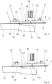
- support 7 is provided with at least one notch 710, e.g. one notch 710.
- Notch 710 substantially is an empty space.
- Notch 710 is provided between two zones 711, 712 ( Figure 6 ) of the first part 71.
- the two zones 711, 712 are joined to each other by a connecting portion of support 7.
- notch 710 is at least partially at, in particular above, said stretch 81. Notch 710 serves in particular to limit the transmission of heat between zone 711 and zone 712 of said first part 71 of support 7.
- the NTC thermistor 91 is fixed to zone 711 and the NTC thermistor 92 is fixed to zone 712.
- the NTC thermistor 91 is thus particularly sensitive to the temperature of the liquid, while the NTC thermistor 92 is particularly sensitive to the temperature of the heating element 8.
- the NTC thermistor 91 advantageously is apt to detect a temperature which conforms more with the temperature of the water during the regular operation of pump 101, while the NTC thermistor 92 is closer to the hot zone and therefore is more reactive in case of lack of water because it is more sensitive to the temperature of the heating element 8.
- both the NTC thermistor 91 and the NTC thermistor 92 read the increase of the temperature due to the superheating of the heating element 8.
- Notch 710 advantageously allows the difference in temperature between the NTC thermistor 91 and the NTC thermistor 92 to be adjusted and allows the NTC thermistor 92 to be substantially at the same temperature as the water.
- Zone 711 of the first part 71 of support 7 is distal from the second part 72 of support 7.
- Zone 712 of the first part 71 of support 7 is proximal, in particular adjacent, to the second part 72 of support 7.
- notch 710 has a thickness equal to the thickness of support 7.
- notch 710 is obtained starting from a portion of the periphery of support 7.
- the width and the depth (or length) of notch 710 may be selected according to the operating needs.
- notch 710 is between the first NTC thermistor 91 and the second NTC thermistor 92, i.e. preferably notch 710 extends between the first NTC thermistor 91 and the second NTC thermistor 92.
- Support 7 is provided with at least one electrically conductive track 51 fixed thereto, e.g. one conductive track 51 ( Figures 4 and 10 ).
- the NTC thermistors 91, 92 are fixed to the electrically conductive track 51, in particular so as to be crossed by an electrical signal with which an ohmic and therefore temperature value may be associated, therethrough.
- a dielectric layer is provided between the electrically conductive track 51 and support 7.
- An electric connector 52 preferably multipolar, is also fixed to support 7.
- the electric connector 52 is three-pole (as shown in the drawings) and in particular, is provided with three electrically conductive legs 521 ( Figures 3 and 4 ) welded to the conductive track 51.
- the electric connector 52 is apt to receive an electrical signal processed by the NTC thermistors 91, 92 by means of the conductive track 51.
- the electric connector 52 is partially arranged at said notch 710, is partially fixed to said first zone 711 of said first part 71 of support 7, and is partially fixed to said second zone 712 of said first part 71 of support 7.
- the electric connector 52 substantially serves as bridge between the first zone 711 and the second zone 712 so as to provide a structural support to compensate for any structural weaknesses induced by the presence of notch 710.
- the electric connector 52 is only partly above notch 710.
- the component 70 ( Figures 4 and 10 ) comprising the support 7, the NTC thermistors 91, 92, the electrically conductive track 51 and preferably also the electric connector 52, substantially is an electronic board which in particular, is a pre-assembled component.
- support 7 is fixed to wall 2 so as to be disassembled from wall 2, in particular so as to be disassembled without damaging components of cover 1.
- first fastening means 77 for example a first nut-stud pair 77
- second fastening means 77 for example a second nut-stud pair 77
- the fastening means comprise an elastic body 76 which applies a force on support 7 to fix it to wall 2.
- the elastic body 76 comprises two flaps 762, 763 between which a central part 761 is provided.
- the flaps 762, 763 are fixed, e.g. welded, to wall 2 so as to bend the middle part 761 so that it applies a force on support 7.
- support 7 may also be welded or brazed to wall 2 or fixed by means of an adhesive.
- cover 1 may in any case be provided with one or more temperature control devices of the electro-mechanical type.
- cover 1 may be provided with a thermostat, in particular of the electro-mechanical and/or thermal fuse type.
- thermostat and/or thermal fuse in particular are fixed to the outer face 6.
- cover 1 in addition to the NTC thermistors 91, 92 and the possible one or more temperature control devices of the electro-mechanical type, may also be provided with one or more further NTC thermistors fixed to the outer face 6 in different positions with respect to the NTC thermistors 91, 92.
Landscapes
- Engineering & Computer Science (AREA)
- Mechanical Engineering (AREA)
- General Engineering & Computer Science (AREA)
- Textile Engineering (AREA)
- Physics & Mathematics (AREA)
- Thermal Sciences (AREA)
- Water Supply & Treatment (AREA)
- General Physics & Mathematics (AREA)
- Automation & Control Theory (AREA)
- Chemical & Material Sciences (AREA)
- Combustion & Propulsion (AREA)
- Cookers (AREA)
- Structures Of Non-Positive Displacement Pumps (AREA)
- Closures For Containers (AREA)
Claims (13)
- Eine Abdeckung (1) für eine Flüssigkeitspumpe (101) für ein Haushaltsgerät, insbesondere für einen Geschirrspüler oder eine Waschmaschine;
die Abdeckung (1) umfasst- eine Wand (2) miteiner Innenseite (4), die dazu bestimmt ist, mit der Flüssigkeit in Kontakt zu kommen, undeine Außenseite (6), die der Innenseite (4) gegenüberliegt;- ein elektrisches Heizelement (8), das die Wand (2) durchquert, wobei das mindestens eine elektrische Heizelement (8) dazu geeignet ist, mit der Flüssigkeit in Kontakt zu kommen;wobei die Wand (2) mindestens einen ersten Abschnitt (21) aufweist, an dem die Innenseite (4) von dem elektrischen Heizelement (8) beabstandet ist;wobei die Wand (2) mindestens einen zweiten Abschnitt (22) aufweist, an dem die Innenseite (4) in Kontakt mit dem elektrischen Heizelement (8) steht;- einen an der Außenseite (6) befestigten Träger (7);dadurch gekennzeichnet, dassdie Abdeckung (1) außerdem mindestens einen ersten NTC-Thermistor (91) und einen zweiten NTC-Thermistor (92) aufweist, die an der Außenseite (6) an dem ersten Abschnitt (21) der Wand (2) befestigt sind;wobei der erste NTC-Thermistor (91) distal von dem zweiten Abschnitt (22) der Wand (2) ist und der zweite NTC-Thermistor (92) proximal zu dem zweiten Abschnitt (22) der Wand (2) ist;wobei der erste NTC-Thermistor (91) und der zweite NTC-Thermistor (92) sich an einem Abschnitt (81) des Heizelements (8) befinden, der von dem ersten Abschnitt (21) der Wand (2) beabstandet ist und dem ersten Abschnitt (21) der Wand (2) zugewandt ist;wobei der erste NTC-Thermistor (91) und der zweite NTC-Thermistor (92) mit Hilfe des Trägers (7) an der Außenseite (6) befestigt sind;wobei der Träger (7) einen ersten Teil (71) aufweist, der mit dem ersten Abschnitt (21) der Wand (2) in Kontakt steht;wobei der erste NTC-Thermistor (91) und der zweite NTC-Thermistor (92) an dem ersten Teil (71) des Trägers (7) befestigt sind;wobei der erste Teil (71) des Trägers (7) eine erste Zone (711) und eine zweite Zone (712) aufweist, zwischen denen mindestens eine Kerbe (710) vorgesehen ist, insbesondere um die Wärmeübertragung zwischen der ersten Zone (711) und der zweiten Zone (712) des ersten Teils (71) des Trägers (7) zu begrenzen;wobei der erste NTC-Thermistor (91) an der ersten Zone (711) und der zweite NTC-Thermistor (92) an der zweiten Zone (712) befestigt ist. - Eine Abdeckung (1) nach Anspruch 1, wobei der erste NTC-Thermistor (91) und der zweite NTC-Thermistor (92) oberhalb des Abschnitts (81) liegen.
- Eine Abdeckung (1) nach Anspruch 1 oder 2, wobei der Träger (7) einen zweiten Teil (72) aufweist, der mit dem zweiten Abschnitt (22) der Wand (2) in Kontakt steht.
- Eine Abdeckung (1) nach Anspruch 3, wobei die erste Zone (711) des ersten Teils (71) des Trägers (7) distal von dem zweiten Teil (72) des Trägers (7) ist und wobei die zweite Zone (712) des ersten Teils (71) des Trägers (7) proximal zu dem zweiten Teil (72) des Trägers (7) ist.
- Eine Abdeckung (1) nach einem der vorhergehenden Ansprüche, wobei der Träger (7) mit mindestens einer elektrisch leitenden Bahn (51) versehen ist;
und wobei der erste NTC-Thermistor (91) und der zweite NTC-Thermistor (92) an der mindestens einen elektrisch leitenden Bahn (51) befestigt sind. - Eine Abdeckung (1) nach Anspruch 5, wobei der Träger (7) aus Metall hergestellt ist und wobei eine dielektrische Schicht zwischen der mindestens einen elektrisch leitenden Spur (51) und dem Träger (7) vorgesehen ist.
- Eine Abdeckung (1) nach einem der vorhergehenden Ansprüche, wobei der Träger (7) an der Wand (2) so befestigt ist, dass er von der Wand (2) demontierbar ist.
- Eine Abdeckung (1) nach einem der vorhergehenden Ansprüche, wobei der Träger (7) an der Wand (2) durch Befestigungsmittel (77) befestigt ist, die eine Verbindung durch Verschrauben und/oder durch Befestigungsmittel, die mindestens einen elastischen Körper (76) aufweisen, und/oder durch Schweißen oder Löten und/oder durch einen Klebstoff herstellen.
- Eine Abdeckung (1) nach einem der vorhergehenden Ansprüche, wobei ein elektrischer Verbinder (52) vorgesehen ist, der an dem Träger (7) befestigt ist.
- Eine Abdeckung (1) nach Anspruch 9, wobei der elektrische Verbinder (52) teilweise an der Kerbe (710) angeordnet ist, teilweise in der ersten Zone (711) des ersten Teils (71) des Trägers (7) befestigt ist und teilweise in der zweiten Zone (712) des ersten Teils (71) des Trägers (7) befestigt ist.
- Eine Abdeckung (1) nach einem der vorhergehenden Ansprüche, wobei der Träger (7) eine Achse (Z), insbesondere eine Längsachse, definiert, und wobei die Achse (Z) sich an einem Teil des Abschnitts (81) des Heizelements (8), der von dem ersten Abschnitt (21) der Wand (2) beabstandet ist und dem ersten Abschnitt (21) der Wand (2) zugewandt ist, befindet, insbesondere an diesem ausgerichtet ist.
- Eine Abdeckung (1) nach einem der vorhergehenden Ansprüche, wobei die mindestens eine Kerbe (710) mindestens teilweise an, insbesondere oberhalb, des Abschnitts (81) liegt.
- Eine Pumpe (101) für ein Haushaltsgerät, die einen Deckel (1) nach einem der vorhergehenden Ansprüche aufweist.
Applications Claiming Priority (2)
| Application Number | Priority Date | Filing Date | Title |
|---|---|---|---|
| IT102020000006253A IT202000006253A1 (it) | 2020-03-25 | 2020-03-25 | Coperchio per pompa per un elettrodomestico |
| PCT/IB2021/052422 WO2021191809A1 (en) | 2020-03-25 | 2021-03-24 | Pump cover for a household appliance |
Publications (2)
| Publication Number | Publication Date |
|---|---|
| EP4125532A1 EP4125532A1 (de) | 2023-02-08 |
| EP4125532B1 true EP4125532B1 (de) | 2024-09-11 |
Family
ID=70805131
Family Applications (1)
| Application Number | Title | Priority Date | Filing Date |
|---|---|---|---|
| EP21719712.8A Active EP4125532B1 (de) | 2020-03-25 | 2021-03-24 | Deckel für eine pumpe für ein haushaltsgerät |
Country Status (5)
| Country | Link |
|---|---|
| US (1) | US12492713B2 (de) |
| EP (1) | EP4125532B1 (de) |
| CN (1) | CN115605119B (de) |
| IT (1) | IT202000006253A1 (de) |
| WO (1) | WO2021191809A1 (de) |
Families Citing this family (1)
| Publication number | Priority date | Publication date | Assignee | Title |
|---|---|---|---|---|
| DE102022213727A1 (de) * | 2022-12-15 | 2024-06-20 | Robert Bosch Gesellschaft mit beschränkter Haftung | Vorintegriertes Thermomanagement-Modul, Fahrzeug und Verfahren |
Family Cites Families (29)
| Publication number | Priority date | Publication date | Assignee | Title |
|---|---|---|---|---|
| US5117089A (en) * | 1990-04-02 | 1992-05-26 | Emerson Electric Co. | Structural support for hermetic terminal assembly heater apparatus |
| US5058197A (en) * | 1990-04-02 | 1991-10-15 | Emerson Electric Co. | Heater apparatus for fluid medium in a hermetically sealed chamber |
| US5635092A (en) * | 1992-03-10 | 1997-06-03 | Otter Controls Limited | Controls for electrically heated water boiling vessels |
| GB9205159D0 (en) * | 1992-03-10 | 1992-04-22 | Otter Controls Ltd | Improvements relating to electrically powered immersion heating elements and controls thereof |
| US5257341A (en) * | 1992-06-19 | 1993-10-26 | A-Dec, Inc. | Compact in-line thermostatically controlled electric water heater for use with dental instruments |
| US5560060A (en) * | 1995-01-10 | 1996-10-01 | General Electric Company | System and method for adjusting the operating cycle of a cleaning appliance |
| AUPN560795A0 (en) * | 1995-09-25 | 1995-10-19 | Stokes (Australasia) Limited | Heating element assembly |
| US6282372B1 (en) * | 2000-04-11 | 2001-08-28 | Rheem Manufacturing Company | Multi-position point of use electric water heater |
| DE10062540A1 (de) * | 2000-12-15 | 2002-06-20 | Bleckmann Gmbh Lamprechtshause | Heizvorrichtung mit Aufweitkörper zur Montage in einer Wandöffnung |
| US6611660B1 (en) * | 2002-04-30 | 2003-08-26 | Cool Options, Inc. A New Hampshire Corp. | Radial fin thermal transfer element and method of manufacturing same |
| US6915069B2 (en) * | 2003-07-14 | 2005-07-05 | Ken A. Bradenbaugh | Temperature sensor assembly, water heater including the temperature sensor assembly, and method of sensing a temperature |
| DE10356790A1 (de) * | 2003-12-04 | 2005-07-07 | BSH Bosch und Siemens Hausgeräte GmbH | Heizvorrichtung für Fluide, Durchlauferhitzer und Verfahren zu deren Herstellung |
| DE102004060949A1 (de) * | 2003-12-23 | 2006-02-09 | BSH Bosch und Siemens Hausgeräte GmbH | Dickschichtheizung für Fluide und Durchlauferhitzer |
| SE0502643L (sv) * | 2005-12-02 | 2007-02-13 | Calix Automotive Ab | En anordning |
| DE102006028913A1 (de) * | 2006-06-21 | 2007-12-27 | Aweco Appliance Systems Gmbh & Co. Kg | Pumpe, insbesondere für wasserführende Haushaltsmaschinen |
| CA2599746A1 (en) * | 2007-08-13 | 2009-02-13 | James Straley | Immersion heater and method of manufacture |
| US8150246B1 (en) * | 2008-07-22 | 2012-04-03 | Niagara Industries, Inc. | Tankless water heater assembly |
| FR2996299B1 (fr) * | 2012-09-28 | 2018-07-13 | Valeo Systemes Thermiques | Dispositif de conditionnement thermique de fluide pour vehicule automobile et appareil de chauffage et/ou de climatisation correspondant |
| DE102015119832A1 (de) * | 2015-11-17 | 2017-05-18 | Xylem Ip Management Sàrl | Förderpumpe zur Druckerhöhung in einer Leitung und Verfahren zum Betreiben einer Förderpumpe |
| ITUA20161567A1 (it) * | 2016-03-11 | 2017-09-11 | Irca Spa | Coperchio per pompa centrifuga |
| DE202016008761U1 (de) * | 2016-06-20 | 2019-08-29 | Bleckmann Gmbh & Co. Kg | Heizsystemkomponente mit einer kompakten Temperatursensor-Gestaltung |
| EP3540329B1 (de) * | 2016-06-20 | 2021-04-28 | Bleckmann GmbH & Co. KG | Bauteil einer heizungsanlage zur bereitstellung eines kompakten temperatursensordesigns |
| IT201600078782A1 (it) * | 2016-07-27 | 2018-01-27 | Irca Spa | Coperchio per pompa centrifuga |
| DE102016215266A1 (de) * | 2016-08-16 | 2018-02-22 | BSH Hausgeräte GmbH | Baueinheit, insbesondere Heizpumpe, mit einem beheizbaren Rohrabschnitt für ein wasserführendes Haushaltsgerät, sowie wasserführendes Haushaltsgerät mit einer solchen Baueinheit |
| EP3447304B1 (de) * | 2017-08-25 | 2026-04-15 | Sanhua AWECO Appliance Systems GmbH | Dünnschichtiges heizelement für eine flüssigkeitspumpe |
| PL3620097T3 (pl) * | 2018-09-07 | 2021-12-27 | Bleckmann Gmbh & Co. Kg | Układ grzewczy do ogrzewania płynnego czynnika |
| US12274310B2 (en) * | 2020-07-14 | 2025-04-15 | Jupiter Research, Llc | Dry atomizer |
| EP4009741A1 (de) * | 2020-12-03 | 2022-06-08 | Bleckmann GmbH & Co. KG | Heizsystemkomponente zur erfassung einer ersten und einer zweiten temperatur |
| EP4308188A1 (de) * | 2021-03-16 | 2024-01-24 | Fremon Scientific, Inc. | Vorrichtungen und verfahren zum auftauen von biologischen substanzen |
-
2020
- 2020-03-25 IT IT102020000006253A patent/IT202000006253A1/it unknown
-
2021
- 2021-03-24 WO PCT/IB2021/052422 patent/WO2021191809A1/en not_active Ceased
- 2021-03-24 EP EP21719712.8A patent/EP4125532B1/de active Active
- 2021-03-24 CN CN202180023980.5A patent/CN115605119B/zh active Active
- 2021-03-24 US US17/906,530 patent/US12492713B2/en active Active
Also Published As
| Publication number | Publication date |
|---|---|
| CN115605119B (zh) | 2024-12-17 |
| CN115605119A (zh) | 2023-01-13 |
| US12492713B2 (en) | 2025-12-09 |
| WO2021191809A1 (en) | 2021-09-30 |
| US20230122647A1 (en) | 2023-04-20 |
| IT202000006253A1 (it) | 2021-09-25 |
| EP4125532A1 (de) | 2023-02-08 |
Similar Documents
| Publication | Publication Date | Title |
|---|---|---|
| EP3491252B1 (de) | Kreiselpumpenabdeckung | |
| EP3426930B1 (de) | Abdeckung für zentrifugalpumpen | |
| KR102779660B1 (ko) | 간단하고 안전한 작동을 위한 가열 시스템 장치의 제어 방법 및 이를 위한 가열 시스템 장치 | |
| US20140029928A1 (en) | Heating device and electric appliance with heating device | |
| US10278532B2 (en) | Household appliance and electrical heating element for use in a household appliance | |
| CN101460080B (zh) | 用于加热液体的家用电器 | |
| EP2543762B1 (de) | Verfahren zur Feststellung des Tauchzustandes eines Betriebszustandes eines elektrischen Widerstandes für eine Waschmaschine | |
| US6064801A (en) | Heating element assembly for water heater with IC controller and temperature sensor mounted in thermal relation | |
| CN1136853A (zh) | 有关电热沸水器的改进 | |
| US12492713B2 (en) | Pump cover for a household appliance | |
| EP3540329B1 (de) | Bauteil einer heizungsanlage zur bereitstellung eines kompakten temperatursensordesigns | |
| US4394646A (en) | Temperature indicator for a glass ceramic cooking surface | |
| JP2004139894A (ja) | 温度検知装置 | |
| CN112922901A (zh) | 加热器的加热装置及集成加热泵 | |
| EP2137461B1 (de) | Kochvorrichtung mit einer wärmedetektionsvorrichtung | |
| CN209863518U (zh) | 一种带有控温结构的食品加工机 | |
| AU2012265567B2 (en) | Temperature sensing for an electric heating device | |
| AU6980396A (en) | Heating element assembly | |
| GB2379851A (en) | Improved protection against failure of planar heating elements |
Legal Events
| Date | Code | Title | Description |
|---|---|---|---|
| STAA | Information on the status of an ep patent application or granted ep patent |
Free format text: STATUS: UNKNOWN |
|
| STAA | Information on the status of an ep patent application or granted ep patent |
Free format text: STATUS: THE INTERNATIONAL PUBLICATION HAS BEEN MADE |
|
| PUAI | Public reference made under article 153(3) epc to a published international application that has entered the european phase |
Free format text: ORIGINAL CODE: 0009012 |
|
| STAA | Information on the status of an ep patent application or granted ep patent |
Free format text: STATUS: REQUEST FOR EXAMINATION WAS MADE |
|
| 17P | Request for examination filed |
Effective date: 20221024 |
|
| AK | Designated contracting states |
Kind code of ref document: A1 Designated state(s): AL AT BE BG CH CY CZ DE DK EE ES FI FR GB GR HR HU IE IS IT LI LT LU LV MC MK MT NL NO PL PT RO RS SE SI SK SM TR |
|
| DAV | Request for validation of the european patent (deleted) | ||
| DAX | Request for extension of the european patent (deleted) | ||
| P01 | Opt-out of the competence of the unified patent court (upc) registered |
Effective date: 20230525 |
|
| GRAP | Despatch of communication of intention to grant a patent |
Free format text: ORIGINAL CODE: EPIDOSNIGR1 |
|
| STAA | Information on the status of an ep patent application or granted ep patent |
Free format text: STATUS: GRANT OF PATENT IS INTENDED |
|
| INTG | Intention to grant announced |
Effective date: 20240424 |
|
| GRAS | Grant fee paid |
Free format text: ORIGINAL CODE: EPIDOSNIGR3 |
|
| GRAA | (expected) grant |
Free format text: ORIGINAL CODE: 0009210 |
|
| STAA | Information on the status of an ep patent application or granted ep patent |
Free format text: STATUS: THE PATENT HAS BEEN GRANTED |
|
| AK | Designated contracting states |
Kind code of ref document: B1 Designated state(s): AL AT BE BG CH CY CZ DE DK EE ES FI FR GB GR HR HU IE IS IT LI LT LU LV MC MK MT NL NO PL PT RO RS SE SI SK SM TR |
|
| REG | Reference to a national code |
Ref country code: GB Ref legal event code: FG4D |
|
| REG | Reference to a national code |
Ref country code: CH Ref legal event code: EP |
|
| REG | Reference to a national code |
Ref country code: DE Ref legal event code: R096 Ref document number: 602021018656 Country of ref document: DE |
|
| REG | Reference to a national code |
Ref country code: IE Ref legal event code: FG4D |
|
| REG | Reference to a national code |
Ref country code: LT Ref legal event code: MG9D |
|
| PG25 | Lapsed in a contracting state [announced via postgrant information from national office to epo] |
Ref country code: NO Free format text: LAPSE BECAUSE OF FAILURE TO SUBMIT A TRANSLATION OF THE DESCRIPTION OR TO PAY THE FEE WITHIN THE PRESCRIBED TIME-LIMIT Effective date: 20241211 |
|
| REG | Reference to a national code |
Ref country code: NL Ref legal event code: MP Effective date: 20240911 |
|
| PG25 | Lapsed in a contracting state [announced via postgrant information from national office to epo] |
Ref country code: GR Free format text: LAPSE BECAUSE OF FAILURE TO SUBMIT A TRANSLATION OF THE DESCRIPTION OR TO PAY THE FEE WITHIN THE PRESCRIBED TIME-LIMIT Effective date: 20241212 Ref country code: FI Free format text: LAPSE BECAUSE OF FAILURE TO SUBMIT A TRANSLATION OF THE DESCRIPTION OR TO PAY THE FEE WITHIN THE PRESCRIBED TIME-LIMIT Effective date: 20240911 |
|
| PG25 | Lapsed in a contracting state [announced via postgrant information from national office to epo] |
Ref country code: BG Free format text: LAPSE BECAUSE OF FAILURE TO SUBMIT A TRANSLATION OF THE DESCRIPTION OR TO PAY THE FEE WITHIN THE PRESCRIBED TIME-LIMIT Effective date: 20240911 |
|
| PG25 | Lapsed in a contracting state [announced via postgrant information from national office to epo] |
Ref country code: LV Free format text: LAPSE BECAUSE OF FAILURE TO SUBMIT A TRANSLATION OF THE DESCRIPTION OR TO PAY THE FEE WITHIN THE PRESCRIBED TIME-LIMIT Effective date: 20240911 |
|
| PG25 | Lapsed in a contracting state [announced via postgrant information from national office to epo] |
Ref country code: HR Free format text: LAPSE BECAUSE OF FAILURE TO SUBMIT A TRANSLATION OF THE DESCRIPTION OR TO PAY THE FEE WITHIN THE PRESCRIBED TIME-LIMIT Effective date: 20240911 |
|
| PG25 | Lapsed in a contracting state [announced via postgrant information from national office to epo] |
Ref country code: ES Free format text: LAPSE BECAUSE OF FAILURE TO SUBMIT A TRANSLATION OF THE DESCRIPTION OR TO PAY THE FEE WITHIN THE PRESCRIBED TIME-LIMIT Effective date: 20240911 Ref country code: RS Free format text: LAPSE BECAUSE OF FAILURE TO SUBMIT A TRANSLATION OF THE DESCRIPTION OR TO PAY THE FEE WITHIN THE PRESCRIBED TIME-LIMIT Effective date: 20241211 |
|
| PG25 | Lapsed in a contracting state [announced via postgrant information from national office to epo] |
Ref country code: RS Free format text: LAPSE BECAUSE OF FAILURE TO SUBMIT A TRANSLATION OF THE DESCRIPTION OR TO PAY THE FEE WITHIN THE PRESCRIBED TIME-LIMIT Effective date: 20241211 Ref country code: NO Free format text: LAPSE BECAUSE OF FAILURE TO SUBMIT A TRANSLATION OF THE DESCRIPTION OR TO PAY THE FEE WITHIN THE PRESCRIBED TIME-LIMIT Effective date: 20241211 Ref country code: LV Free format text: LAPSE BECAUSE OF FAILURE TO SUBMIT A TRANSLATION OF THE DESCRIPTION OR TO PAY THE FEE WITHIN THE PRESCRIBED TIME-LIMIT Effective date: 20240911 Ref country code: HR Free format text: LAPSE BECAUSE OF FAILURE TO SUBMIT A TRANSLATION OF THE DESCRIPTION OR TO PAY THE FEE WITHIN THE PRESCRIBED TIME-LIMIT Effective date: 20240911 Ref country code: GR Free format text: LAPSE BECAUSE OF FAILURE TO SUBMIT A TRANSLATION OF THE DESCRIPTION OR TO PAY THE FEE WITHIN THE PRESCRIBED TIME-LIMIT Effective date: 20241212 Ref country code: FI Free format text: LAPSE BECAUSE OF FAILURE TO SUBMIT A TRANSLATION OF THE DESCRIPTION OR TO PAY THE FEE WITHIN THE PRESCRIBED TIME-LIMIT Effective date: 20240911 Ref country code: ES Free format text: LAPSE BECAUSE OF FAILURE TO SUBMIT A TRANSLATION OF THE DESCRIPTION OR TO PAY THE FEE WITHIN THE PRESCRIBED TIME-LIMIT Effective date: 20240911 Ref country code: BG Free format text: LAPSE BECAUSE OF FAILURE TO SUBMIT A TRANSLATION OF THE DESCRIPTION OR TO PAY THE FEE WITHIN THE PRESCRIBED TIME-LIMIT Effective date: 20240911 |
|
| REG | Reference to a national code |
Ref country code: AT Ref legal event code: MK05 Ref document number: 1721922 Country of ref document: AT Kind code of ref document: T Effective date: 20240911 |
|
| PG25 | Lapsed in a contracting state [announced via postgrant information from national office to epo] |
Ref country code: NL Free format text: LAPSE BECAUSE OF FAILURE TO SUBMIT A TRANSLATION OF THE DESCRIPTION OR TO PAY THE FEE WITHIN THE PRESCRIBED TIME-LIMIT Effective date: 20240911 |
|
| PG25 | Lapsed in a contracting state [announced via postgrant information from national office to epo] |
Ref country code: IS Free format text: LAPSE BECAUSE OF FAILURE TO SUBMIT A TRANSLATION OF THE DESCRIPTION OR TO PAY THE FEE WITHIN THE PRESCRIBED TIME-LIMIT Effective date: 20250111 Ref country code: PT Free format text: LAPSE BECAUSE OF FAILURE TO SUBMIT A TRANSLATION OF THE DESCRIPTION OR TO PAY THE FEE WITHIN THE PRESCRIBED TIME-LIMIT Effective date: 20250113 |
|
| PG25 | Lapsed in a contracting state [announced via postgrant information from national office to epo] |
Ref country code: RO Free format text: LAPSE BECAUSE OF FAILURE TO SUBMIT A TRANSLATION OF THE DESCRIPTION OR TO PAY THE FEE WITHIN THE PRESCRIBED TIME-LIMIT Effective date: 20240911 Ref country code: SM Free format text: LAPSE BECAUSE OF FAILURE TO SUBMIT A TRANSLATION OF THE DESCRIPTION OR TO PAY THE FEE WITHIN THE PRESCRIBED TIME-LIMIT Effective date: 20240911 |
|
| PG25 | Lapsed in a contracting state [announced via postgrant information from national office to epo] |
Ref country code: EE Free format text: LAPSE BECAUSE OF FAILURE TO SUBMIT A TRANSLATION OF THE DESCRIPTION OR TO PAY THE FEE WITHIN THE PRESCRIBED TIME-LIMIT Effective date: 20240911 Ref country code: AT Free format text: LAPSE BECAUSE OF FAILURE TO SUBMIT A TRANSLATION OF THE DESCRIPTION OR TO PAY THE FEE WITHIN THE PRESCRIBED TIME-LIMIT Effective date: 20240911 |
|
| PG25 | Lapsed in a contracting state [announced via postgrant information from national office to epo] |
Ref country code: CZ Free format text: LAPSE BECAUSE OF FAILURE TO SUBMIT A TRANSLATION OF THE DESCRIPTION OR TO PAY THE FEE WITHIN THE PRESCRIBED TIME-LIMIT Effective date: 20240911 Ref country code: PL Free format text: LAPSE BECAUSE OF FAILURE TO SUBMIT A TRANSLATION OF THE DESCRIPTION OR TO PAY THE FEE WITHIN THE PRESCRIBED TIME-LIMIT Effective date: 20240911 |
|
| PG25 | Lapsed in a contracting state [announced via postgrant information from national office to epo] |
Ref country code: SK Free format text: LAPSE BECAUSE OF FAILURE TO SUBMIT A TRANSLATION OF THE DESCRIPTION OR TO PAY THE FEE WITHIN THE PRESCRIBED TIME-LIMIT Effective date: 20240911 |
|
| REG | Reference to a national code |
Ref country code: DE Ref legal event code: R097 Ref document number: 602021018656 Country of ref document: DE |
|
| PG25 | Lapsed in a contracting state [announced via postgrant information from national office to epo] |
Ref country code: DK Free format text: LAPSE BECAUSE OF FAILURE TO SUBMIT A TRANSLATION OF THE DESCRIPTION OR TO PAY THE FEE WITHIN THE PRESCRIBED TIME-LIMIT Effective date: 20240911 |
|
| PLBE | No opposition filed within time limit |
Free format text: ORIGINAL CODE: 0009261 |
|
| STAA | Information on the status of an ep patent application or granted ep patent |
Free format text: STATUS: NO OPPOSITION FILED WITHIN TIME LIMIT |
|
| 26N | No opposition filed |
Effective date: 20250612 |
|
| PG25 | Lapsed in a contracting state [announced via postgrant information from national office to epo] |
Ref country code: SE Free format text: LAPSE BECAUSE OF FAILURE TO SUBMIT A TRANSLATION OF THE DESCRIPTION OR TO PAY THE FEE WITHIN THE PRESCRIBED TIME-LIMIT Effective date: 20240911 |
|
| PG25 | Lapsed in a contracting state [announced via postgrant information from national office to epo] |
Ref country code: MC Free format text: LAPSE BECAUSE OF FAILURE TO SUBMIT A TRANSLATION OF THE DESCRIPTION OR TO PAY THE FEE WITHIN THE PRESCRIBED TIME-LIMIT Effective date: 20240911 |
|
| REG | Reference to a national code |
Ref country code: CH Ref legal event code: H13 Free format text: ST27 STATUS EVENT CODE: U-0-0-H10-H13 (AS PROVIDED BY THE NATIONAL OFFICE) Effective date: 20251023 |
|
| PG25 | Lapsed in a contracting state [announced via postgrant information from national office to epo] |
Ref country code: LU Free format text: LAPSE BECAUSE OF NON-PAYMENT OF DUE FEES Effective date: 20250324 |
|
| REG | Reference to a national code |
Ref country code: BE Ref legal event code: MM Effective date: 20250331 |
|
| PG25 | Lapsed in a contracting state [announced via postgrant information from national office to epo] |
Ref country code: BE Free format text: LAPSE BECAUSE OF NON-PAYMENT OF DUE FEES Effective date: 20250331 |
|
| PG25 | Lapsed in a contracting state [announced via postgrant information from national office to epo] |
Ref country code: CH Free format text: LAPSE BECAUSE OF NON-PAYMENT OF DUE FEES Effective date: 20250331 |
|
| PG25 | Lapsed in a contracting state [announced via postgrant information from national office to epo] |
Ref country code: IE Free format text: LAPSE BECAUSE OF NON-PAYMENT OF DUE FEES Effective date: 20250324 |
|
| PGFP | Annual fee paid to national office [announced via postgrant information from national office to epo] |
Ref country code: GB Payment date: 20260330 Year of fee payment: 6 |
|
| PGFP | Annual fee paid to national office [announced via postgrant information from national office to epo] |
Ref country code: FR Payment date: 20260330 Year of fee payment: 6 |
|
| PGFP | Annual fee paid to national office [announced via postgrant information from national office to epo] |
Ref country code: TR Payment date: 20260323 Year of fee payment: 6 |
|
| PG25 | Lapsed in a contracting state [announced via postgrant information from national office to epo] |
Ref country code: CY Free format text: LAPSE BECAUSE OF FAILURE TO SUBMIT A TRANSLATION OF THE DESCRIPTION OR TO PAY THE FEE WITHIN THE PRESCRIBED TIME-LIMIT Effective date: 20240911 |
|
| PG25 | Lapsed in a contracting state [announced via postgrant information from national office to epo] |
Ref country code: LT Free format text: LAPSE BECAUSE OF FAILURE TO SUBMIT A TRANSLATION OF THE DESCRIPTION OR TO PAY THE FEE WITHIN THE PRESCRIBED TIME-LIMIT Effective date: 20240911 |
|
| PGFP | Annual fee paid to national office [announced via postgrant information from national office to epo] |
Ref country code: IT Payment date: 20260326 Year of fee payment: 6 |
|
| PGFP | Annual fee paid to national office [announced via postgrant information from national office to epo] |
Ref country code: DE Payment date: 20260428 Year of fee payment: 6 |