EP4527435A2 - Arzneimittelabgabevorrichtung - Google Patents
Arzneimittelabgabevorrichtung Download PDFInfo
- Publication number
- EP4527435A2 EP4527435A2 EP25150109.4A EP25150109A EP4527435A2 EP 4527435 A2 EP4527435 A2 EP 4527435A2 EP 25150109 A EP25150109 A EP 25150109A EP 4527435 A2 EP4527435 A2 EP 4527435A2
- Authority
- EP
- European Patent Office
- Prior art keywords
- plunger
- indicator
- drug delivery
- delivery device
- trigger mechanism
- Prior art date
- Legal status (The legal status is an assumption and is not a legal conclusion. Google has not performed a legal analysis and makes no representation as to the accuracy of the status listed.)
- Pending
Links
Images


Classifications
-
- A—HUMAN NECESSITIES
- A61—MEDICAL OR VETERINARY SCIENCE; HYGIENE
- A61M—DEVICES FOR INTRODUCING MEDIA INTO, OR ONTO, THE BODY; DEVICES FOR TRANSDUCING BODY MEDIA OR FOR TAKING MEDIA FROM THE BODY; DEVICES FOR PRODUCING OR ENDING SLEEP OR STUPOR
- A61M5/00—Devices for bringing media into the body in a subcutaneous, intra-vascular or intramuscular way; Accessories therefor, e.g. filling or cleaning devices, arm-rests
- A61M5/178—Syringes
- A61M5/31—Details
- A61M5/315—Pistons; Piston-rods; Guiding, blocking or restricting the movement of the rod or piston; Appliances on the rod for facilitating dosing ; Dosing mechanisms
- A61M5/31565—Administration mechanisms, i.e. constructional features, modes of administering a dose
- A61M5/31566—Means improving security or handling thereof
- A61M5/3157—Means providing feedback signals when administration is completed
-
- A—HUMAN NECESSITIES
- A61—MEDICAL OR VETERINARY SCIENCE; HYGIENE
- A61M—DEVICES FOR INTRODUCING MEDIA INTO, OR ONTO, THE BODY; DEVICES FOR TRANSDUCING BODY MEDIA OR FOR TAKING MEDIA FROM THE BODY; DEVICES FOR PRODUCING OR ENDING SLEEP OR STUPOR
- A61M5/00—Devices for bringing media into the body in a subcutaneous, intra-vascular or intramuscular way; Accessories therefor, e.g. filling or cleaning devices, arm-rests
- A61M5/178—Syringes
- A61M5/20—Automatic syringes, e.g. with automatically actuated piston rod, with automatic needle injection, filling automatically
- A61M5/2033—Spring-loaded one-shot injectors with or without automatic needle insertion
-
- A—HUMAN NECESSITIES
- A61—MEDICAL OR VETERINARY SCIENCE; HYGIENE
- A61M—DEVICES FOR INTRODUCING MEDIA INTO, OR ONTO, THE BODY; DEVICES FOR TRANSDUCING BODY MEDIA OR FOR TAKING MEDIA FROM THE BODY; DEVICES FOR PRODUCING OR ENDING SLEEP OR STUPOR
- A61M5/00—Devices for bringing media into the body in a subcutaneous, intra-vascular or intramuscular way; Accessories therefor, e.g. filling or cleaning devices, arm-rests
- A61M5/178—Syringes
- A61M5/31—Details
- A61M5/32—Needles; Details of needles pertaining to their connection with syringe or hub; Accessories for bringing the needle into, or holding the needle on, the body; Devices for protection of needles
- A61M5/3205—Apparatus for removing or disposing of used needles or syringes, e.g. containers; Means for protection against accidental injuries from used needles
- A61M5/321—Means for protection against accidental injuries by used needles
- A61M5/3243—Means for protection against accidental injuries by used needles being axially-extensible, e.g. protective sleeves coaxially slidable on the syringe barrel
-
- A—HUMAN NECESSITIES
- A61—MEDICAL OR VETERINARY SCIENCE; HYGIENE
- A61M—DEVICES FOR INTRODUCING MEDIA INTO, OR ONTO, THE BODY; DEVICES FOR TRANSDUCING BODY MEDIA OR FOR TAKING MEDIA FROM THE BODY; DEVICES FOR PRODUCING OR ENDING SLEEP OR STUPOR
- A61M5/00—Devices for bringing media into the body in a subcutaneous, intra-vascular or intramuscular way; Accessories therefor, e.g. filling or cleaning devices, arm-rests
- A61M5/178—Syringes
- A61M5/20—Automatic syringes, e.g. with automatically actuated piston rod, with automatic needle injection, filling automatically
- A61M2005/2006—Having specific accessories
- A61M2005/2013—Having specific accessories triggering of discharging means by contact of injector with patient body
-
- A—HUMAN NECESSITIES
- A61—MEDICAL OR VETERINARY SCIENCE; HYGIENE
- A61M—DEVICES FOR INTRODUCING MEDIA INTO, OR ONTO, THE BODY; DEVICES FOR TRANSDUCING BODY MEDIA OR FOR TAKING MEDIA FROM THE BODY; DEVICES FOR PRODUCING OR ENDING SLEEP OR STUPOR
- A61M2205/00—General characteristics of the apparatus
- A61M2205/58—Means for facilitating use, e.g. by people with impaired vision
- A61M2205/581—Means for facilitating use, e.g. by people with impaired vision by audible feedback
-
- A—HUMAN NECESSITIES
- A61—MEDICAL OR VETERINARY SCIENCE; HYGIENE
- A61M—DEVICES FOR INTRODUCING MEDIA INTO, OR ONTO, THE BODY; DEVICES FOR TRANSDUCING BODY MEDIA OR FOR TAKING MEDIA FROM THE BODY; DEVICES FOR PRODUCING OR ENDING SLEEP OR STUPOR
- A61M2205/00—General characteristics of the apparatus
- A61M2205/58—Means for facilitating use, e.g. by people with impaired vision
- A61M2205/582—Means for facilitating use, e.g. by people with impaired vision by tactile feedback
Definitions
- the present disclosure relates to a drug delivery device comprising an audible and/or tactile indicator mechanism.
- Administering an injection is a process which presents a number of risks and challenges for users and healthcare professionals, both mental and physical.
- Drug delivery devices typically fall into two categories - manual drug delivery devices or autoinjectors.
- manual force is required to drive a medicament through a needle. This is typically done by some form of plunger that has to be continuously pressed during the injection.
- plunger that has to be continuously pressed during the injection.
- Autoinjector devices aim to make self-injection easier for patients.
- a conventional autoinjector may provide the force for administering the injection by a spring, and trigger button or other mechanism may be used to activate the injection.
- Autoinjectors may be single-use or reusable devices.
- An object of the present disclosure is to provide an improved drug delivery device.
- the object is achieved by a drug delivery device according to claim 1.
- a drug delivery device comprises at least a housing adapted to receive a cartridge or primary container with a piston and a plunger slidably disposed in the housing and adapted to drive the piston for delivering a drug or a medicament.
- the device further comprises a drive spring pre-loaded between the housing and the plunger so as to urge the plunger towards a distal direction.
- an audible and/or tactile indicator e.g. a resilient force member, is provided, e.g. disposed at a proximal end of the device, in particular at a proximal end of the housing.
- a trigger mechanism for activating the indicator is provided and arranged between the indicator and the plunger, wherein the trigger mechanism is configured to support the indicator in an initial state of the device and/or during delivery of the medicament and to couple with the plunger to activate the audible and/or tactile indicator at or near an end of delivery, in particular when the plunger is in a distal position.
- the trigger mechanism engages with the plunger to activate the audible and/or tactile indicator at or near the end of delivery of the medicament.
- said indicator disengages from the support of the trigger mechanism.
- the trigger mechanism is being engaging with the plunger the trigger mechanism is being disengaged from the indicator to activate the indicator.
- the indicator can deform or relax when its support is disengaged.
- the indicator can disengage from the support by the trigger mechanism.
- the indicator is engaged, e.g. in contact, with the trigger mechanism in the initial state and during injection.
- the trigger mechanism supports the indicator in an initial state, e.g. unbiased state, or in a biased state.
- the trigger mechanism may hold or press the indicator in or into an initial state, e.g. unbiased state, or in or into a biased state.
- the trigger mechanism only supports the indicator before its activation.
- Such a drug delivery device ensures that the trigger mechanism fires or activates the indicator regardless of the length of the plunger. Hence, the length of the plunger could be changed without affecting activation or firing of the indicator. Furthermore, the number of parts, which would have to be replaced to accommodate a change in dose delivered by the drug delivery device, is minimised.
- the trigger mechanism comprises at least one structure resiliently abutting the plunger.
- the at least one structure resiliently abuts the plunger before activating of the indicator.
- the at least one structure may protrude from an indicator holder towards the plunger.
- the at least one structure may protrude from the housing towards the plunger.
- the housing can also be configured to hold the indicator.
- the holder may be formed as a part of an inner housing so a separate indicator holder is not required.
- the structure may protrude from the housing, for example from an inner part of the housing towards the plunger.
- the structure comprises at least one fin.
- the plunger may comprise at least one cut-out adapted to receive the at least one structure at or near the end of delivery, in particular when the plunger is in a distal position.
- the cut-out comprises a lateral inclined edge.
- the lateral inclined edge supports and ensures catching of the fin.
- the cut-out may comprise a distal stepped edge. This edge secures the coupling with the fin, in particular with the distal stepped edge of the fin.
- the guide pin and the guide rail are configured to engage each other, e.g. coaxially to the longitudinal axis.
- the guide pin may comprise a guide pin surface engaging a corresponding guide rail surface of the guide rail.
- the guide pin surface and the guide rail surface may be oppositely inclined to each other.
- the guide pin surface and the guide rail surface may be engaged to each other in an angle between 30° and 60°, in particular between 40° and 50°.
- the guide rail may be formed as a protruding elongated rib extending in parallel to the longitudinal axis.
- the elongated rib ensures a guiding of the pin during delivery of the medicament.
- the drug delivery device may be an auto-injector, a pen-injector or a syringe.
- the primary container may be prefilled with a drug.
- the drug delivery device may be configured to inject a drug or medicament into a patient.
- delivery could be sub-cutaneous, intra-muscular, or intravenous.
- Such a device could be operated by a patient or care-giver, such as a nurse or physician, and can include various types of safety syringe, pen-injector, or auto-injector.
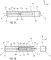
- Device 10 includes a housing 11 which typically contains a reservoir or cartridge containing the medicament to be injected (e.g., a syringe 24 or a container) and the components required to facilitate one or more steps of the delivery process.
- a housing 11 typically contains a reservoir or cartridge containing the medicament to be injected (e.g., a syringe 24 or a container) and the components required to facilitate one or more steps of the delivery process.
- the needle 17 can be retracted within sleeve 13 or housing 11. Retraction can occur when sleeve 13 moves distally as a user removes device 10 from a patient's body. This can occur as needle 17 remains fixedly located relative to housing 11. Once a distal end of the sleeve 13 has moved past a distal end of the needle 17, and the needle 17 is covered, the sleeve 13 can be locked. Such locking can include locking any proximal movement of the sleeve 13 relative to the housing 11.
- the housing may comprise a window 11a through which the syringe 24 can be monitored.
- distal section/end refers to the section/end of the device 10, or the sections/ends of the components thereof, which during use of the device 10 is located closest to a medicament delivery site of a patient.
- proximal section/end refers to the section/end of the device 10, or the sections/ends of the components thereof, which during use of the device 10 is pointing away from the medicament delivery site of the patient.
- the drug delivery device 10 comprises the housing 11 with a front case 11.1 and a rear case 11.2.
- the front case 11.1 is adapted to hold the medicament container or primary container 24, such as a syringe.
- the medicament primary container is referred to hereinafter as the "syringe 24".
- the syringe 24 may be a pre-filled syringe, in particular a 1.0 ml pre-filled syringe, containing a medicament and having the needle 17 arranged at a distal end of the syringe 24.
- the medicament container may be a primary container which includes the medicament and engages a removable needle (e.g., by threads, snaps, friction, etc.).
- the drug delivery device 10 may be configured as an autoinjector or as a manual drug delivery device.
- the drug delivery device 10 comprises an audible and/or tactile indicator 50 providing an audible and/or tactile indication to a user of the device 10 at the end of delivery of the medicament.
- the indicator 50 produces an audible and/or tactile feedback for a user or patient indicating completion of medicament delivery.
- the indicator 50 is provided to indicate to a user or a patient that the full dose of medicament was spent.
- the indicator 50 is disposed at the proximal end P of the device 10.
- the indicator 50 is arranged at a proximal end of the housing 11 and inside the housing 11.
- a trigger mechanism 60 is arranged between the indicator 50 and the plunger 40.
- the trigger mechanism 60 is configured to support the indicator 50 in an initial state of the device 10, for example during storage and transportation as well as during delivery of the medicament and to couple with the plunger 40 to activate the indicator 50 at an end of delivery.
- the trigger mechanism 60 engages with the plunger 40 to activate the audible and/or tactile indicator 50 at or near the end of delivery of the medicament.
- the indicator 50 is engaged, e.g. in contact, with the trigger mechanism in the initial state and during injection.
- the trigger mechanism 60 supports the indicator 50 in an initial state, e.g. unbiased state, or in a biased state.
- the trigger mechanism 60 may hold or press the indicator 50 in or into an initial state, e.g. unbiased state, or in or into a biased state.
- the trigger mechanism 60 only supports the indicator 50 before its activation and releases it upon activating.
- the indicator 50 is formed as a biasing member, a spring, a laminated spring, a flat spring, a plate spring or a leaf spring.
- the trigger mechanism 60 comprises at least one structure, e.g. a protrusion, a flap, projection, resiliently abutting the plunger 40.
- the at least one structure resiliently abuts the plunger 40 before activating of the indicator 50.
- a part of the trigger mechanism 60 e.g. one surface side, for instance an outer side of the trigger mechanism 60, abuts and supports the indicator 50 and an opposite surface side, e.g. an inner side of the trigger mechanism 60, abuts the plunger 40 before activating of the indicator 50, e.g. before and during delivery of the medicament.
- the trigger mechanism 60 Upon activating of the indicator 50, the trigger mechanism 60 disengages from indicator 50 and a part of the trigger mechanism 60 couples or engages with the plunger 40.
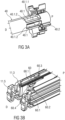
- FIGS 2A to 4C respectively show embodiments of the indicator 50 which will be described further below.
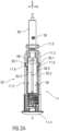
- FIG 2A shows a longitudinal section of an exemplary embodiment of the rear case 11.2.
- the rear case 11.2 serves for example as a drive subassembly 11.4 of the drug delivery device 10.
- the drive sub assembly 11.4 is a sub assembly of the drug delivery device 10 and comprises the components required to deliver the medicament.
- the drive subassembly 11.4 comprises for example the rear case 11.2, the plunger 40, the drive spring 30 and the indicator 50.
- the drug delivery device 10 further comprises a front sub assembly (not shown separately) to allow for flexibility as to the time and location of manufacture of the subassemblies and final assembly with the syringe 24.
- the rear case 11.2 comprises two support arms 11.3 adapted to support an axial position of the syringe 24 during storage, transportation and medicament delivery.
- the support arms 11.3 project distally from a proximal case end 11.4 of the rear case 11.2.
- the rear case 11.2 further comprises additional flexible projections 11.5 that project distally from the distal end of the rear case 11.2 as well.
- the flexible projections 11.5 project distally from the distal end of the support arms 11.3.
- the projections 11.5 are adapted to damp impact forces and thus to stabilize the syringe 24 during storage, transportation and delivery.
- the indicator 50 is arranged on the housing 11, in particular on the rear case 11.2.
- the indicator 50 is arranged on an outer side of at least one of the support arms 11.3.
- the trigger mechanism 60 is also arranged on the rear case 11.2.
- the trigger mechanism 60 is arranged on an inner side of the support arm 11.3 and thus on a side opposite the side of the support arms 11.3 where the indicator 50 is arranged.
- the trigger mechanism 60 is adapted to damp impact forces and thus to stabilize the indicator 50 in its biased state during storage, transportation, and medicament delivery.
- the indicator 50 may arranged on a holder (not shown) which is arranged in the housing 11.
- the trigger mechanism 60 may then also be arranged on the holder in a similar manner as on the rear case 11.2.
- the indicator 50 is arranged within the device 10 at the proximal end P of housing 11.
- a proximal end of the plunger 40 is at least partially received within the rear case 11.2.
- the rear case 11.2 is closed at its outer proximal end 11.4.
- the indicator 50 is held in the rear case 11.2 such that the longitudinal axis X is in parallel with a longitudinal extension of the drug delivery device 10.
- the indicator 50 may be coupled to the drug delivery device 10 by a snap connection, wherein one or more of the tabs 50.1 are engaged within a number of corresponding openings 11.6 in the rear case 11.2.
- the indicator 50 is held in the rear case 11.2 by a frictional connection, such as a screw or rivet connection or interference fit.
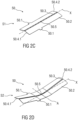
- Figures 2A and 2C show the indicator 50 in a pre-assembly state and initial or relaxed state S1.
- Figure 2B shows the indicator 50 in an assembly state in the rear case 11.2 and in a primed or biased state S2 and figure 2D shows the indicator in the biased state S2, too.
- the indicator 50 comprises a resilient force member 50.2, e.g. having a substantially rectangular shape, comprising a longitudinal axis running in parallel to the longest side of the outer circumference of the resilient force member 50.2.
- the resilient force member 50.2 may have a triangular shape or any other geometrical shape suitable to couple the indicator 50 to the device 10, e.g. an autoinjector.
- the resilient force member 50.2 may be designed as a monostable leaf spring comprising a resilient material, e. g. spring steel or spring plastic.
- the resilient force member 50.2 is capable of residing in two states. That is, the resilient force member 50.2 may assume two different conformations, one of them stable with limited or no application of an external force and the other one unstable.
- these two states can include a first or relaxed state S1 (or pre-assembly state, or trigged state, or initial state), in which the resilient force member 50.2 has a first conformation.
- a second or biased state S2 or primed state
- the resilient force member 50.2 can have a second conformation.
- the resilient force member 50.2 is in the relaxed state S1 which can correspond to the pre-assembly state as well as to a state at the end of medicament delivery.
- the resilient force member 50.2 comprises a longitudinal bend 50.3.
- the longitudinal bend 50.3 can be arranged generally in the centre of the resilient force member 50.2 running in parallel to the longitudinal axis X.
- the longitudinal bend 50.3 can divide the indicator 50 into two wing-shaped sections angled to each other with an angle less than 180 degrees. In in the illustrated perspective of figures 2A and 2C , the wing-shaped sections are angled downwards.
- the resilient force member 50.2 can comprise one or more tabs 50.1 projecting perpendicularly to the longitudinal axis X from the outer circumference.
- the resilient force member 50.2 can include one, two, three, four or more tabs 50.1.
- the resilient force member 50.2 includes two tabs 50.1, wherein one of the tabs 50.1 is arranged opposite the other tab 50.1.
- the resilient force member 50.2 can include pairs of tabs 50.1 located generally opposite each other. The pairs of tabs 50.1 are arranged spaced to each other in the direction of the longitudinal axis X.
- the number and arrangement of the tabs 50.1 may differ from the shown exemplary embodiment.
- the tabs 50.1 may be angled with respect to the wing-shaped sections to facilitate assembly of the drug delivery device 10.
- the resilient force member 50.2 is bent in the centre about an axis A running perpendicular to the longitudinal axis X.
- the bending angle may be less than 90 degrees. This bending is achieved by applying a predetermined force onto or near the centre point of the resilient force member 50.2 when engaging the tabs 50.1 within the openings 11.6 in the rear case 11.2.
- the resilient force member 50.2 changes from the relaxed state S1 into the biased state S2.
- Two ends 50.4.1, 50.4.2 of the resilient force member 50.2 at opposite ends along the longitudinal axis X are angled upwards from the centre point 50.5 in the illustrated perspective of figure 2C , which shows the biased state S2.
- the biased state S2 corresponds with the primed state, wherein the resilient force member 50.2 stores a certain amount of energy.
- the resilient force member 50.2 is held in the biased state S2 as it is shown in figure 2C and described below.
- the resilient force member 50.2 is in the biased state S2 and held in the rear case 11.2 by the snap connection as described above.
- the distally pointing end 50.4.1 of the resilient force member 50.2 and the biased state S2 of the indicator 50 is supported and activated by the trigger mechanism 60 arranged on the support arm 11.3 as described further below.
- the proximally pointing end 50.4.2 of the resilient force member 50.2 is free and not in contact with any other component and located above the trigger mechanism 60 or another section of the rear case 11.2.
- the trigger mechanism 60 comprises at least one structure 60.1 resiliently abutting the plunger 40.
- the structure 60.1 may protrude from an indicator holder towards the plunger 40.
- the structure 60.1 may be formed as a fin.
- the protruding structure 60.1 is referred to hereinafter as "fin 60.1". Due to the support of the fin 60.1 on the plunger 40 during storage, transportation and delivery, the indicator 50 is supported in its biased state S2, too.
- the at least one fin 60.1 protrudes from the housing 11, in particular from the rear case 11.2, e.g. from its inner support arm 11.3 towards the plunger 40.
- the support arm 11.3 is formed as an indicator holder.
- the indicator 50 and the fin 60.1 are arranged on opposite surface side of the support arm 11.3.
- the indicator 50 is held on a surface side of arm 11.3 facing to the outer housing 11.
- the fin 60.1 is formed on the opposite side of the arm 11.3 facing inwards and towards to the plunger 40.
- the fin 60.1 may protrude from a separate indicator holder (not shown) towards the plunger 40.
- the separate indicator holder may be arranged between the indicator 50 and the plunger 40 within the housing 11.
- the fin 60.1 has an inclined surface 60.2.
- an upper or top surface of the fin 60.1 is rounded or inclined.
- the inclined surface 60.2 ensures guiding along the plunger 40 during delivery of the medicament.
- the fin 60.1 may comprise a proximal inclined end 60.3 and a distal stepped edge 60.4.
- the proximal inclined end 60.3 allows an easy coupling of the fin 60.1 with the plunger 40.
- the distal stepped edge 60.4 is configured to secure the coupling of the fin 60.1 with the plunger 40.
- the plunger 40 comprises at least one cut-out 40.1 adapted to receive the at least one fin 60.1 at the end of delivery, for example when the plunger 40 is in the distal position. Due to the fin 60.1 falling into the cut-out 40.1 at the end of delivery, the indicator 50 relaxes and generates an acoustic noise. Additionally, the indicator 50 may be configured to generate a tactile feedback on the outer housing 11, too. The indicator 50 thus provides an end-of-delivery feedback to a user.
- the cut-out 40.1 may comprise a lateral inclined edge 40.1.1. Such a lateral inclined edge 40.1.1 facilitates the fin 60.1 falling into the cut-out 40.1.
- the cut-out 40.1 may further comprise a distal stepped edge 40.1.2.
- the distal stepped edge 40.1.2 corresponds with the distal stepped edge 60.4 of the fin 60.1 to facilitate the coupling of the fin 60.1 and the cut-out 40.1.
- the trigger mechanism 60 comprises two adjacent fins 60.1 and the plunger 40 comprises two correspondingly adjacent cut-outs 40.1 adapted to receive the fins 60.1.
- the two fins 60.1 are arranged spaced to each other in the direction of the transversal direction.
- the pair of fins 60.1 protrudes from the inner surface of the rear case 11.2 facing the plunger 40 when received inside the housing 11.
- the radially inwardly protruding and adjacent fins 60.1 abut the plunger 40, thereby supporting the resilient force member 50.2 in its biased state S2.
- the number and arrangement of the fins 60.1 may differ from the shown exemplary embodiment.
- the number and arrangement of the indicators 50 and trigger mechanism 60 may differ from the shown exemplary embodiment.
- the device 10 may comprise two trigger mechanism 60 and two indicators 50 described above. Each of a pair of trigger mechanism 60 and indicators 50 may be arranged on one of the support arms 11.3 of the rear case 11.2.
- the plunger 40 is driven by a drive spring 30 that is arranged between the plunger 40 and the rear case 11.2.
- the drive spring 30 may be arranged within the plunger 40 and be pre-loaded such as to urge the plunger 40 towards the distal end D of the device 10.
- two circumferentially adjacent cut-outs 40.1 corresponding to the adjacent fins 60.1 of the trigger mechanism 60 are arranged near the proximal end P of the plunger 40.
- the plunger 40 is aligned in an angular position relative to the rear case 11.2 such that each of the fins 60.1 is axially aligned with its corresponding cut-out 40.1.
- the plunger 40 is translated in a distal direction towards a distal position until reaching a position at the end of the injection, where the fins 60.1 will snap into the cut-outs 40.1.
- the resilient force member 50.2 will relax from its biased state S2 into its relaxed state S1.
- An audible and/or tactile click emitted upon this relaxation indicates the end of the injection process to the user.
- the fins 60.1 are formed in the shape of shark fins with a proximally arranged inclined end 60.3 and with a distally arranged stepped edge 60.4.
- the resilient force member 50.2 relaxes immediately with a sharp click noise, when the plunger 40 reaches its distal end position.
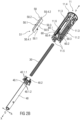
- Figure 4A shows a further aspect of the disclosure concerning the sleeve 13 comprising a guide rail 13.2.
- Figure 4B shows a guide pin 40.2 corresponding to the guide rail 13.2 and protruding from a proximal end of the plunger 40.
- Figure 4C is a schematic view of a guiding mechanism for guiding the plunger 40 along the needle sleeve 13 due to the interrelation of guide pin 40.2 and guide rail 13.2.
- the needle sleeve 13 is telescopically coupled to the housing 11 and has an inner surface 13.1 with at least one radially inwardly protruding guide rail 13.2 extending in parallel to the longitudinal axis X.
- the guide rail 13.2 is formed for example as a protruding rib elongated parallel to the longitudinal axis X.
- the plunger 40 may comprise at least one radially outwardly protruding guide pin 40.2.
- the guide pin 40.2 and the guide rail 13.2 are configured to engage each other, e.g. coaxially to the longitudinal axis X.
- the guide pin 40.2 engages the at least one guide rail 13.2 as best seen in figure 4C .
- the drug delivery device 10 may be an auto-injector, a pen-injector or a syringe.
- the primary container or syringe 24 may be prefilled with a drug.
- the drug container may be or may include a dual-chamber cartridge configured to store two or more components of a drug formulation (e.g., a drug and a diluent, or two different types of drugs) separately, one in each chamber.
- the two chambers of the dual-chamber cartridge may be configured to allow mixing between the two or more components of the drug or medicament prior to and/or during dispensing into the human or animal body.
- the two chambers may be configured such that they are in fluid communication with each other (e.g., by way of a conduit between the two chambers) and allow mixing of the two components when desired by a user prior to dispensing.
- the two chambers may be configured to allow mixing as the components are being dispensed into the human or animal body.
- Exemplary polysaccharides include a glucosaminoglycane, a hyaluronic acid, a heparin, a low molecular weight heparin or an ultra-low molecular weight heparin or a derivative thereof, or a sulphated polysaccharide, e.g. a poly-sulphated form of the above-mentioned polysaccharides, and/or a pharmaceutically acceptable salt thereof.
- An example of a pharmaceutically acceptable salt of a poly-sulphated low molecular weight heparin is enoxaparin sodium.
- An example of a hyaluronic acid derivative is Hylan G-F 20 / Synvisc, a sodium hyaluronate.
- antibody refers to an immunoglobulin molecule or an antigen-binding portion thereof.
- antigen-binding portions of immunoglobulin molecules include F(ab) and F(ab') 2 fragments, which retain the ability to bind antigen.
- the antibody can be polyclonal, monoclonal, recombinant, chimeric, de-immunized or humanized, fully human, non-human, (e.g., murine), or single chain antibody.
- the antibody has effector function and can fix complement.
- the antibody has reduced or no ability to bind an Fc receptor.
- the antibody can be an isotype or subtype, an antibody fragment or mutant, which does not support binding to an Fc receptor, e.g., it has a mutagenized or deleted Fc receptor binding region.
Landscapes
- Health & Medical Sciences (AREA)
- Engineering & Computer Science (AREA)
- Heart & Thoracic Surgery (AREA)
- Vascular Medicine (AREA)
- Anesthesiology (AREA)
- Biomedical Technology (AREA)
- Hematology (AREA)
- Life Sciences & Earth Sciences (AREA)
- Animal Behavior & Ethology (AREA)
- General Health & Medical Sciences (AREA)
- Public Health (AREA)
- Veterinary Medicine (AREA)
- Environmental & Geological Engineering (AREA)
- Infusion, Injection, And Reservoir Apparatuses (AREA)
Applications Claiming Priority (3)
| Application Number | Priority Date | Filing Date | Title |
|---|---|---|---|
| EP17306518 | 2017-11-03 | ||
| EP18793225.6A EP3703783B1 (de) | 2017-11-03 | 2018-11-01 | Arzneimittelabgabevorrichtung |
| PCT/EP2018/079915 WO2019086561A1 (en) | 2017-11-03 | 2018-11-01 | Drug delivery device |
Related Parent Applications (1)
| Application Number | Title | Priority Date | Filing Date |
|---|---|---|---|
| EP18793225.6A Division EP3703783B1 (de) | 2017-11-03 | 2018-11-01 | Arzneimittelabgabevorrichtung |
Publications (2)
| Publication Number | Publication Date |
|---|---|
| EP4527435A2 true EP4527435A2 (de) | 2025-03-26 |
| EP4527435A3 EP4527435A3 (de) | 2025-05-14 |
Family
ID=60302040
Family Applications (2)
| Application Number | Title | Priority Date | Filing Date |
|---|---|---|---|
| EP18793225.6A Active EP3703783B1 (de) | 2017-11-03 | 2018-11-01 | Arzneimittelabgabevorrichtung |
| EP25150109.4A Pending EP4527435A3 (de) | 2017-11-03 | 2018-11-01 | Arzneimittelabgabevorrichtung |
Family Applications Before (1)
| Application Number | Title | Priority Date | Filing Date |
|---|---|---|---|
| EP18793225.6A Active EP3703783B1 (de) | 2017-11-03 | 2018-11-01 | Arzneimittelabgabevorrichtung |
Country Status (6)
| Country | Link |
|---|---|
| US (2) | US11654246B2 (de) |
| EP (2) | EP3703783B1 (de) |
| JP (2) | JP7382928B2 (de) |
| CN (1) | CN111587132B (de) |
| DK (1) | DK3703783T3 (de) |
| WO (1) | WO2019086561A1 (de) |
Families Citing this family (19)
| Publication number | Priority date | Publication date | Assignee | Title |
|---|---|---|---|---|
| TW201709941A (zh) | 2015-06-03 | 2017-03-16 | 賽諾菲阿凡提斯德意志有限公司 | 聲響指示器(二) |
| TW201707737A (zh) | 2015-06-03 | 2017-03-01 | 賽諾菲阿凡提斯德意志有限公司 | 藥物輸送裝置(一) |
| TW201700118A (zh) | 2015-06-03 | 2017-01-01 | 賽諾菲阿凡提斯德意志有限公司 | 藥物輸送裝置(三) |
| TW201709940A (zh) | 2015-06-03 | 2017-03-16 | 賽諾菲阿凡提斯德意志有限公司 | 聲響指示器(一) |
| CA3195450A1 (en) * | 2020-11-13 | 2022-05-19 | Anders Holmqvist | Medicament delivery device |
| WO2022253852A1 (en) * | 2021-06-02 | 2022-12-08 | Sanofi | Drug delivery device, plunger rod, set of plunger rods, method for assembling a drug delivery device and set of drug delivery devices |
| EP4611855A1 (de) | 2022-10-31 | 2025-09-10 | Sanofi | Akustischer indikator, indikatorhalter und verfahren zur montage eines akustischen indikators |
| EP4611853A1 (de) | 2022-10-31 | 2025-09-10 | Sanofi | Anordnung für eine arzneimittelabgabevorrichtung |
| WO2024094704A1 (en) | 2022-10-31 | 2024-05-10 | Sanofi | Arrangement for a drug delivery device, drug delivery device and method for assembly |
| WO2024094700A1 (en) | 2022-10-31 | 2024-05-10 | Sanofi | Method for assembling an assembly for a drug delivery device and drug delivery device. |
| EP4611848A1 (de) | 2022-10-31 | 2025-09-10 | Sanofi | Vorrichtungskörper für eine arzneimittelabgabevorrichtung, anordnung für eine arzneimittelabgabevorrichtung und arzneimittelabgabevorrichtung |
| CN120500361A (zh) | 2022-10-31 | 2025-08-15 | 赛诺菲 | 具有反馈元件的药物递送装置以及用于向药物递送装置的用户提供关于剂量分配过程的反馈的方法 |
| EP4611854A1 (de) | 2022-10-31 | 2025-09-10 | Sanofi | Arzneimittelabgabevorrichtung mit zweiteiligem benutzerindikator |
| CN120476001A (zh) | 2022-10-31 | 2025-08-12 | 赛诺菲 | 用于药物递送装置的前子组件 |
| EP4611846A1 (de) | 2022-10-31 | 2025-09-10 | Sanofi | Kolben zum ausstossen eines arzneimittels, arzneimittelabgabevorrichtung, hintere unteranordnung und zugehörige verfahren |
| WO2024094699A1 (en) | 2022-10-31 | 2024-05-10 | Sanofi | Container holder and drug delivery device comprising the container holder |
| WO2025162928A1 (en) | 2024-01-29 | 2025-08-07 | Sanofi | Needle shroud unlock device for a medicament delivery device |
| WO2025162927A1 (en) | 2024-01-29 | 2025-08-07 | Sanofi | Purifying device, system and method for purifying a needle for delivering a medicament |
| WO2025162926A1 (en) | 2024-01-29 | 2025-08-07 | Sanofi | Needle arrangement, drug delivery device comprising the needle arrangement and method for operating the drug delivery device |
Family Cites Families (61)
| Publication number | Priority date | Publication date | Assignee | Title |
|---|---|---|---|---|
| DE7833454U1 (de) | 1978-11-10 | 1979-05-10 | Fohlmeister, Claus, 2000 Hamburg | Spielzeug |
| US4693711A (en) | 1981-12-22 | 1987-09-15 | Bremer Roger E | Long-life biomedical transcutaneous drug application device and method of transcutaneous application of drugs |
| US4629454A (en) | 1985-03-29 | 1986-12-16 | Grier Dale C | Hypodermic syringe |
| DE3645245C2 (de) | 1986-11-14 | 1994-01-27 | Haselmeier Wilhelm Fa | Injektionsgerät |
| US4810249A (en) | 1987-03-12 | 1989-03-07 | Habley Medical Technology Corp. | Linear and Vernier-type syringe |
| US5127906A (en) | 1989-04-28 | 1992-07-07 | Flp Enterprises, Inc. | Non-reusable syringe |
| DE3935672A1 (de) | 1989-05-20 | 1990-11-22 | Dirk Breimeyer | Durchflussmessgeraet |
| CA1325149C (en) | 1989-08-31 | 1993-12-14 | Gavin Mcgregor | Variable intensity remote controlled needleless injector |
| US5271527A (en) | 1992-04-02 | 1993-12-21 | Habley Medical Technology Corporation | Reusable pharmaceutical dispenser with full stroke indicator |
| US5391157A (en) | 1992-10-20 | 1995-02-21 | Eli Lilly And Company | End of dose indicator |
| PT2258424E (pt) | 2001-05-16 | 2013-03-28 | Lilly Co Eli | Aparelho injector de medicamento |
| US20050027255A1 (en) * | 2003-07-31 | 2005-02-03 | Sid Technologies, Llc | Automatic injector |
| FR2861995A1 (fr) | 2003-11-10 | 2005-05-13 | Mb Innovation | Dispositif a usage unique de pulverisation d'un fluide medicamenteux |
| BRPI0607012A2 (pt) | 2005-01-25 | 2009-12-01 | Novo Nordisk As | dispositivo de injeção |
| EP2258441A3 (de) | 2005-09-02 | 2011-09-21 | Intercell USA, Inc. | Vorrichtungen für die transkutane Abgabe von Vakzinen und transdermale Abgabe von Arzneimitteln |
| US7611495B1 (en) | 2005-10-07 | 2009-11-03 | Gianturco Michael C | Device for manually controlling delivery rate of a hypodermic syringe and syringe having same |
| US9808611B2 (en) | 2006-05-19 | 2017-11-07 | Oxyband Technologies, Inc. | Systems and methods for enhancing gas and vapor transfer for tissue treatment devices |
| CN200987443Y (zh) | 2006-08-10 | 2007-12-12 | 何文华 | 一种新型的防盗钱包 |
| CN201111673Y (zh) | 2007-08-01 | 2008-09-10 | 上海维恩佳得数码科技有限公司 | 用于瓶装商品的防盗标签 |
| US10188787B2 (en) | 2007-12-31 | 2019-01-29 | Deka Products Limited Partnership | Apparatus, system and method for fluid delivery |
| US20090248085A1 (en) | 2008-03-31 | 2009-10-01 | Cochlear Limited | Tissue injection fixation system for a prosthetic device |
| JP5653345B2 (ja) | 2008-05-12 | 2015-01-14 | カレオ,インコーポレイテッド | 電子回路システムを有する薬剤デリバリデバイス |
| CN201243374Y (zh) | 2008-07-02 | 2009-05-20 | 东莞市三正华声电子科技有限公司 | 耳机音量调节控制装置 |
| EP2362792B1 (de) | 2008-09-29 | 2017-11-01 | Becton Dickinson France | Autoinjektor mit hörbarer anzeige der vollständigen abgabe |
| WO2010035059A1 (en) | 2008-09-29 | 2010-04-01 | Becton Dickinson France | Automatic injection device with audible indicator of completed injection |
| US20110105952A1 (en) | 2009-10-30 | 2011-05-05 | Seventh Sense Biosystems, Inc. | Relatively small devices applied to the skin, modular systems, and methods of use thereof |
| EP2451508B1 (de) * | 2009-07-08 | 2013-11-06 | Novo Nordisk A/S | Frostsichere injektionsvorrichtung |
| WO2011079278A1 (en) | 2009-12-23 | 2011-06-30 | Becton, Dickinson And Company | Monodose nasal drug delivery device |
| CN102740909B (zh) | 2010-02-01 | 2016-05-04 | 赛诺菲-安万特德国有限公司 | 药筒保持器、给药装置和用于将药筒固定在药筒保持器中的方法 |
| CN103120819B (zh) | 2010-03-31 | 2015-05-06 | Shl集团有限责任公司 | 药物输送设备 |
| WO2012022810A2 (en) | 2010-08-19 | 2012-02-23 | Novo Nordisk A/S | Medical injection device |
| WO2012045350A1 (en) | 2010-10-06 | 2012-04-12 | Tecpharma Licensing Ag | Locking and retaining mechanism for the needle guard sleeve of an injection device |
| GB2488578B (en) | 2011-03-02 | 2017-05-24 | Owen Mumford Ltd | Injection device |
| GB2488579A (en) | 2011-03-02 | 2012-09-05 | Owen Mumford Ltd | Autoinjector with "injection complete" indicator |
| US9131900B2 (en) | 2011-07-11 | 2015-09-15 | Covidien Lp | Force regulating device applicators |
| AU2012306064B2 (en) | 2011-09-09 | 2017-02-23 | Merck Patent Gmbh | An auto-injector for epinephrine injection |
| US20130090605A1 (en) | 2011-09-29 | 2013-04-11 | Animas Corporation | Tunable mechanical injection device for medication |
| EP2583706A1 (de) | 2011-10-21 | 2013-04-24 | Sanofi-Aventis Deutschland GmbH | Automatischer Injektor |
| EP2583705A1 (de) * | 2011-10-21 | 2013-04-24 | Sanofi-Aventis Deutschland GmbH | Anzeigeanordnung für einen automatischen Injektor |
| CN103177716A (zh) | 2011-12-22 | 2013-06-26 | 海洋王照明科技股份有限公司 | 便携式灯具 |
| CN104519929B (zh) | 2012-07-06 | 2017-03-22 | 卡贝欧洲有限公司 | 药物输送装置 |
| CN202887394U (zh) | 2012-08-27 | 2013-04-17 | 叶凯 | 家用地震报警器 |
| CN102842236A (zh) | 2012-08-30 | 2012-12-26 | 江苏永钢集团有限公司 | 一种激光超高报警系统及报警方法 |
| US9675754B2 (en) | 2012-10-24 | 2017-06-13 | Nuance Designs, LLC | Autoinjector |
| EP2727617A1 (de) | 2012-11-06 | 2014-05-07 | Sanofi-Aventis Deutschland GmbH | Autoinjektor |
| US10124115B2 (en) | 2013-03-13 | 2018-11-13 | Antares Pharma, Inc. | Push button safety injector |
| DK2968786T3 (da) | 2013-03-13 | 2020-12-14 | Sanofi Aventis Deutschland | Enhed til medicinafgivelsesanordning med en feedbackfunktion |
| EP2968783B1 (de) | 2013-03-13 | 2021-04-21 | Sanofi-Aventis Deutschland GmbH | Anordnung für eine arzneimittelabgabevorrichtung mit einer rückmeldungsfunktion |
| US20140276568A1 (en) | 2013-03-15 | 2014-09-18 | Morris Elijah Worden | Systems and methods for dampening friction in an autoinjector device |
| EP2781230B2 (de) | 2013-03-22 | 2025-05-14 | Ypsomed AG | Substanzabgabevorrichtung mit Signalvorrichtung |
| CN103235538A (zh) | 2013-04-17 | 2013-08-07 | 四川华川工业有限公司 | 一种破玻器的电路控制系统 |
| EP2823838A1 (de) * | 2013-07-09 | 2015-01-14 | Sanofi-Aventis Deutschland GmbH | Autoinjektor |
| EP2823839A1 (de) | 2013-07-09 | 2015-01-14 | Sanofi-Aventis Deutschland GmbH | Autoinjektor |
| GB2516896B (en) | 2013-08-05 | 2020-08-12 | Owen Mumford Ltd | Injection devices |
| EP2868338A1 (de) | 2013-10-31 | 2015-05-06 | Sanofi-Aventis Deutschland GmbH | Medikamentenabgabevorrichtung |
| TW201603849A (zh) | 2014-07-01 | 2016-02-01 | 賽諾菲公司 | 響片配置及其藥物輸送裝置 |
| TW201709940A (zh) * | 2015-06-03 | 2017-03-16 | 賽諾菲阿凡提斯德意志有限公司 | 聲響指示器(一) |
| TW201709941A (zh) | 2015-06-03 | 2017-03-16 | 賽諾菲阿凡提斯德意志有限公司 | 聲響指示器(二) |
| TW201707737A (zh) | 2015-06-03 | 2017-03-01 | 賽諾菲阿凡提斯德意志有限公司 | 藥物輸送裝置(一) |
| TW201711713A (zh) | 2015-06-03 | 2017-04-01 | 賽諾菲阿凡提斯德意志有限公司 | 藥物輸送裝置(五) |
| DK3703784T3 (da) | 2017-11-03 | 2025-11-24 | Sanofi Sa | Anordning til indgivelse af lægemidler |
-
2018
- 2018-11-01 DK DK18793225.6T patent/DK3703783T3/da active
- 2018-11-01 EP EP18793225.6A patent/EP3703783B1/de active Active
- 2018-11-01 JP JP2020524233A patent/JP7382928B2/ja active Active
- 2018-11-01 EP EP25150109.4A patent/EP4527435A3/de active Pending
- 2018-11-01 WO PCT/EP2018/079915 patent/WO2019086561A1/en not_active Ceased
- 2018-11-01 US US16/759,488 patent/US11654246B2/en active Active
- 2018-11-01 CN CN201880085047.9A patent/CN111587132B/zh active Active
-
2023
- 2023-04-05 US US18/296,088 patent/US20230277777A1/en active Pending
- 2023-08-02 JP JP2023125954A patent/JP2023145665A/ja not_active Abandoned
Also Published As
| Publication number | Publication date |
|---|---|
| WO2019086561A1 (en) | 2019-05-09 |
| CN111587132A (zh) | 2020-08-25 |
| DK3703783T3 (da) | 2025-03-31 |
| JP7382928B2 (ja) | 2023-11-17 |
| CN111587132B (zh) | 2022-10-04 |
| EP3703783A1 (de) | 2020-09-09 |
| US11654246B2 (en) | 2023-05-23 |
| JP2023145665A (ja) | 2023-10-11 |
| EP3703783B1 (de) | 2025-01-08 |
| US20200289764A1 (en) | 2020-09-17 |
| JP2021501638A (ja) | 2021-01-21 |
| EP4527435A3 (de) | 2025-05-14 |
| US20230277777A1 (en) | 2023-09-07 |
Similar Documents
| Publication | Publication Date | Title |
|---|---|---|
| US20230277777A1 (en) | Drug Delivery Device | |
| US20220305206A1 (en) | Drug Delivery Device | |
| US12186540B2 (en) | Drug delivery device with feedback mechanism | |
| US11583636B2 (en) | Drug delivery device | |
| US20250195782A1 (en) | Drug Delivery Device with Drive Sub-Assembly | |
| US11766521B2 (en) | Drive subassembly for a drug delivery device | |
| EP4289457A2 (de) | Medikamenteninjektorvorrichtung | |
| EP3836994B1 (de) | Injektionsvorrichtung | |
| EP3703789B1 (de) | Steuerungsbaugruppe für eine arzneimittelabgabevorrichtung | |
| US12616798B2 (en) | Drug delivery device | |
| HK40055623A (en) | An injection device | |
| HK40055623B (en) | An injection device | |
| HK40036717B (en) | Subassembly for a drug delivery device and drug delivery device | |
| HK40036717A (en) | Subassembly for a drug delivery device and drug delivery device | |
| HK1247876B (en) | Drug delivery device with feedback mechanism |
Legal Events
| Date | Code | Title | Description |
|---|---|---|---|
| PUAI | Public reference made under article 153(3) epc to a published international application that has entered the european phase |
Free format text: ORIGINAL CODE: 0009012 |
|
| STAA | Information on the status of an ep patent application or granted ep patent |
Free format text: STATUS: THE APPLICATION HAS BEEN PUBLISHED |
|
| AC | Divisional application: reference to earlier application |
Ref document number: 3703783 Country of ref document: EP Kind code of ref document: P |
|
| AK | Designated contracting states |
Kind code of ref document: A2 Designated state(s): AL AT BE BG CH CY CZ DE DK EE ES FI FR GB GR HR HU IE IS IT LI LT LU LV MC MK MT NL NO PL PT RO RS SE SI SK SM TR |
|
| REG | Reference to a national code |
Ref country code: DE Ref legal event code: R079 Free format text: PREVIOUS MAIN CLASS: A61M0005320000 Ipc: A61M0005200000 |
|
| PUAL | Search report despatched |
Free format text: ORIGINAL CODE: 0009013 |
|
| AK | Designated contracting states |
Kind code of ref document: A3 Designated state(s): AL AT BE BG CH CY CZ DE DK EE ES FI FR GB GR HR HU IE IS IT LI LT LU LV MC MK MT NL NO PL PT RO RS SE SI SK SM TR |
|
| RIC1 | Information provided on ipc code assigned before grant |
Ipc: A61M 5/32 20060101ALI20250410BHEP Ipc: A61M 5/315 20060101ALI20250410BHEP Ipc: A61M 5/20 20060101AFI20250410BHEP |
|
| STAA | Information on the status of an ep patent application or granted ep patent |
Free format text: STATUS: REQUEST FOR EXAMINATION WAS MADE |
|
| 17P | Request for examination filed |
Effective date: 20251021 |