EP2968786B1 - Anordnung für eine arzneimittelabgabevorrichtung mit einer feedbackfunktion - Google Patents
Anordnung für eine arzneimittelabgabevorrichtung mit einer feedbackfunktion Download PDFInfo
- Publication number
- EP2968786B1 EP2968786B1 EP14708566.6A EP14708566A EP2968786B1 EP 2968786 B1 EP2968786 B1 EP 2968786B1 EP 14708566 A EP14708566 A EP 14708566A EP 2968786 B1 EP2968786 B1 EP 2968786B1
- Authority
- EP
- European Patent Office
- Prior art keywords
- feature
- feedback
- actuator
- tactile
- snap
- Prior art date
- Legal status (The legal status is an assumption and is not a legal conclusion. Google has not performed a legal analysis and makes no representation as to the accuracy of the status listed.)
- Active
Links
Images


Classifications
-
- A—HUMAN NECESSITIES
- A61—MEDICAL OR VETERINARY SCIENCE; HYGIENE
- A61M—DEVICES FOR INTRODUCING MEDIA INTO, OR ONTO, THE BODY; DEVICES FOR TRANSDUCING BODY MEDIA OR FOR TAKING MEDIA FROM THE BODY; DEVICES FOR PRODUCING OR ENDING SLEEP OR STUPOR
- A61M5/00—Devices for bringing media into the body in a subcutaneous, intra-vascular or intramuscular way; Accessories therefor, e.g. filling or cleaning devices, arm-rests
- A61M5/178—Syringes
- A61M5/31—Details
- A61M5/315—Pistons; Piston-rods; Guiding, blocking or restricting the movement of the rod or piston; Appliances on the rod for facilitating dosing ; Dosing mechanisms
- A61M5/31565—Administration mechanisms, i.e. constructional features, modes of administering a dose
- A61M5/31566—Means improving security or handling thereof
- A61M5/3157—Means providing feedback signals when administration is completed
-
- A—HUMAN NECESSITIES
- A61—MEDICAL OR VETERINARY SCIENCE; HYGIENE
- A61M—DEVICES FOR INTRODUCING MEDIA INTO, OR ONTO, THE BODY; DEVICES FOR TRANSDUCING BODY MEDIA OR FOR TAKING MEDIA FROM THE BODY; DEVICES FOR PRODUCING OR ENDING SLEEP OR STUPOR
- A61M2205/00—General characteristics of the apparatus
- A61M2205/58—Means for facilitating use, e.g. by people with impaired vision
- A61M2205/581—Means for facilitating use, e.g. by people with impaired vision by audible feedback
-
- A—HUMAN NECESSITIES
- A61—MEDICAL OR VETERINARY SCIENCE; HYGIENE
- A61M—DEVICES FOR INTRODUCING MEDIA INTO, OR ONTO, THE BODY; DEVICES FOR TRANSDUCING BODY MEDIA OR FOR TAKING MEDIA FROM THE BODY; DEVICES FOR PRODUCING OR ENDING SLEEP OR STUPOR
- A61M2205/00—General characteristics of the apparatus
- A61M2205/58—Means for facilitating use, e.g. by people with impaired vision
- A61M2205/582—Means for facilitating use, e.g. by people with impaired vision by tactile feedback
-
- A—HUMAN NECESSITIES
- A61—MEDICAL OR VETERINARY SCIENCE; HYGIENE
- A61M—DEVICES FOR INTRODUCING MEDIA INTO, OR ONTO, THE BODY; DEVICES FOR TRANSDUCING BODY MEDIA OR FOR TAKING MEDIA FROM THE BODY; DEVICES FOR PRODUCING OR ENDING SLEEP OR STUPOR
- A61M5/00—Devices for bringing media into the body in a subcutaneous, intra-vascular or intramuscular way; Accessories therefor, e.g. filling or cleaning devices, arm-rests
- A61M5/178—Syringes
- A61M5/31—Details
- A61M5/315—Pistons; Piston-rods; Guiding, blocking or restricting the movement of the rod or piston; Appliances on the rod for facilitating dosing ; Dosing mechanisms
- A61M5/31533—Dosing mechanisms, i.e. setting a dose
- A61M5/31545—Setting modes for dosing
- A61M5/31548—Mechanically operated dose setting member
- A61M5/3155—Mechanically operated dose setting member by rotational movement of dose setting member, e.g. during setting or filling of a syringe
- A61M5/31551—Mechanically operated dose setting member by rotational movement of dose setting member, e.g. during setting or filling of a syringe including axial movement of dose setting member
-
- A—HUMAN NECESSITIES
- A61—MEDICAL OR VETERINARY SCIENCE; HYGIENE
- A61M—DEVICES FOR INTRODUCING MEDIA INTO, OR ONTO, THE BODY; DEVICES FOR TRANSDUCING BODY MEDIA OR FOR TAKING MEDIA FROM THE BODY; DEVICES FOR PRODUCING OR ENDING SLEEP OR STUPOR
- A61M5/00—Devices for bringing media into the body in a subcutaneous, intra-vascular or intramuscular way; Accessories therefor, e.g. filling or cleaning devices, arm-rests
- A61M5/178—Syringes
- A61M5/31—Details
- A61M5/315—Pistons; Piston-rods; Guiding, blocking or restricting the movement of the rod or piston; Appliances on the rod for facilitating dosing ; Dosing mechanisms
- A61M5/31565—Administration mechanisms, i.e. constructional features, modes of administering a dose
- A61M5/31576—Constructional features or modes of drive mechanisms for piston rods
- A61M5/31583—Constructional features or modes of drive mechanisms for piston rods based on rotational translation, i.e. movement of piston rod is caused by relative rotation between the user activated actuator and the piston rod
- A61M5/31585—Constructional features or modes of drive mechanisms for piston rods based on rotational translation, i.e. movement of piston rod is caused by relative rotation between the user activated actuator and the piston rod performed by axially moving actuator, e.g. an injection button
Definitions
- the present disclosure relates to an assembly for a drug delivery device.
- the assembly comprises a feedback feature
- an assembly for a drug delivery device comprising at least one feedback feature.
- the feedback feature may be configured to indicate the end of a dispense operation to a user by giving an audible and/or tactile feedback.
- the audible feedback may be, for example, an audible click.
- the tactile feedback may be, for example, an impact on the skin of a user, in particular on a user's finger.
- the tactile feedback may be a vibration of a part of the assembly.
- the feedback may be a well-defined signal.
- the feedback may indicate to a user that the actuator may be released and the device may be withdrawn from a user's skin.
- a feedback feature being configured to indicate the end of a dispense operation is that a clear indication is given to a user when a dispense operation has been completed.
- the use of the drug delivery device may be easy for a user.
- the dosing accuracy of a drug delivery device may be increased.
- it may be inhibited that a user interrupts a dispense operation for example by withdrawing the drug delivery device from the skin, before a complete dose has been delivered.
- a feedback provides an additional benefit for visually impaired users.
- the assembly comprises an actuator which is configured to be operated by a user in order to dispense a dose.
- a feedback may be created when the actuator reaches an end position at the end of a dispense operation.
- the end position of the actuator may be a most distal position of the actuator.
- the term "most distal position" may describe a position of a part of the assembly which is closest to a dispensing end of the drug delivery device.
- the actuator may be in its end position when it is fully depressed into the drug delivery device.
- the actuator may be configured as a button.
- the feedback may be created when the actuator is close to its end position.
- the at least one feedback feature comprises at least one snap feature which is configured to snap through when it is compressed above a certain load, thereby giving a feedback to a user.
- the snap feature may produce an audible signal.
- the snap feature is configured to snap through at the end of a dispense operation.
- the snap feature is configured to snap through when the actuator reaches its end position. Initially during compression of the snap feature, the stiffness of the snap feature may remain fairly constant. At a certain point, the stiffness of the snap feature may reduce significantly. Thereby, the force required to cause a further deflection of the snap feature may decrease. This may cause the snap-through behaviour of the snap feature.
- the snap feature may relax to its initial shape after the dispense operation, in particular when the snap feature is not compressed anymore. When the snap feature relaxes, it may produce a further audible signal.
- the feedback feature in particular the snap feature may comprise the shape of a dome, or the feedback feature may comprise the shape of an arched disk.
- the feedback feature comprises at least one recess.
- the recess may be, for example, a concave cut out. Due to the at least one recess, the feedback feature may comprise a sufficient flexibility. Thereby, the feedback feature may be configured to snap through when it is compressed above a certain load.
- the size and shape of the recess may influence the force which is necessary to cause the feedback feature to snap through.
- the snap feature may be free of any recess. Thereby, the feedback signal may be more distinct.
- the at least one feedback feature comprises a metal material.
- the at least one feedback feature may comprise a plastic material.
- the feedback feature comprises a resilient material.
- the assembly comprises a member which is configured to interact with the feedback feature.
- the member may be configured to axially move, in particular when it does not interact with the feedback feature.
- the member is configured to axially move during an initial phase of a dispense operation.
- the interaction of the axially moveable member with the feedback feature may cause the feedback.
- the axially moveable member may be a sleeve member.
- the feedback feature may be configured to be compressed between two parts of the assembly.
- the feedback feature may be compressed between the actuator and the axially moveable member.
- the feedback feature could be compressed between the housing and the driver.
- the member may axially move with respect to a housing of the drug delivery device between two stops at least during the setting of a dose.
- the member may be temporarily restrained between these two stops. Thereby, the member may be temporarily axially fixed.
- the member may be axially fixed when it interacts with the feedback feature, i. e. when the actuator contacts the feedback feature.
- the actuator interacts with the feedback feature, in particular with the snap feature.
- the actuator may interact with the feedback feature during a dispense operation.
- the feedback feature in particular the snap feature, may be arranged between the actuator and the axially moveable member.
- the feedback feature may be clamped between the actuator and the axially moveable member.
- the feedback feature may be compressed by the actuator.
- the force on the feedback feature increases when the actuator is further moved towards the other part.
- the actuator may exert a force on the feedback feature during a dispense operation.
- the assembly comprises an enhancement feature being configured to enhance the feedback of the feedback feature.
- the volume of an audible feedback may be increased.
- a tactile feedback may be enhanced.
- an audible feedback may be enhanced by an additional tactile feedback or vice versa.
- the enhancement feature may be attached to the axially moveable member.
- the enhancement feature may be an integral part of the axially moveable member.
- the enhancement feature may be a protrusion of the axially moveable member.
- the enhancement feature may comprise a flexible section, in particular a flexible section of the axially moveable member.
- the enhancement feature may be attached to another part of the assembly, for example to a housing.
- the member interacting with the feedback feature comprises a rigid section and a flexible section.
- the flexible section of the member may be configured to be compressed during the dispense operation.
- the flexible section may be compressed at the beginning of an interaction of the axially moveable member with the feedback feature, in particular with the snap feature.
- the flexible section may be located at a fixed part of the drug delivery device, for example at a housing.
- the axially moveable member is configured to expand in an axial direction when the feedback feature, in particular the snap feature snaps through.
- the flexible section may expand in an axial direction when the snap feature snaps through.
- the flexible section may be configured to expand in a direction towards a proximal end of the device.
- the proximal end may be an end which is furthest away from a dispensing end of the device.
- the axially moveable member may further compress the snap feature. Due to the flexible section, the axially moveable member may act as a spring member.
- a resulting feedback may be louder and more energetic than with a fully rigid member interacting with the feedback feature.
- the stiffness of the contact constraints on the feedback feature may be reduced.
- the contact constrains may be constraints which limit a movement of the feedback feature.
- the enhancement feature in particular due to flexibility of the axially moveable member, the feedback feature may vibrate with a larger amplitude and for a longer duration, because of a reduced energy transmission of the feedback feature to the contacting components.
- the flexible section comprises at least one opening.
- the opening may be located in a side wall of the axially moveable member. Due to the at least one opening, the flexibility of the flexible section may be achieved.
- the feedback feature comprises an opening, wherein at least one element of the assembly extends through the opening.
- the actuator may extend through the opening.
- the at least one feedback feature comprises at least one tactile feature which is configured to give a tactile feedback to a user at the end of a dispense operation.
- the tactile feature may be configured as an enhancement feature.
- a tactile feedback may be given by the tactile feature in addition to an audible feedback given by the feedback feature or given by a further feedback feature.
- a tactile feedback which may be given to a user for example due to a snap-through of the snap feature may be enhanced.
- a tactile feedback which derives from a vibration of the snap feature may be enhanced by a tactile feature which may directly contact a user's skin.
- the at least one tactile feature is configured to protrude from the actuator at the end of a dispense operation.
- the at least one tactile feature is configured to protrude through an opening at the end of a dispense operation.
- the opening may be located in the actuator.
- the tactile feature may get in contact with the skin of a user.
- a tactile feedback may be given to a user.
- the feedback feature comprises a snap feature, wherein the at least one tactile feature snaps out when the snap feature snaps through.
- the snapping through of the snap feature may cause a fast and well-defined movement of the tactile feature with respect to the actuator.
- the tactile feature may be axially fixed at the end of a dispense operation, and the actuator may move towards the distal end of the device, thereby causing the tactile feature to snap out.
- the tactile feature may move towards the proximal end of the device while the actuator moves towards the distal end of the device at the end of a dispense operation. Thereby, the speed with which the tactile feature snaps out may be increased. This may lead to a stronger tactile signal.
- the snap feature may create an audible and tactile feedback. The feedback of the snap feature may be enhanced by the tactile feature.
- the at least one tactile feature may be attached to the member interacting with the feedback feature, in particular to the axially moveable member.
- the tactile feature comprises the shape of an arm, which may extend from the moveable member.
- the assembly may comprise a plurality of tactile features, for example three. The tactile features may be arranged circumferentially around the member.
- the at least one tactile feature extends from the member in a proximal direction.
- a drug delivery device comprising an assembly which is configured as previously described.
- the drug delivery device may comprise a feedback feature, which is configured to indicate an end of a dispense operation to a user by giving an audible and/or tactile feedback.
- the drug delivery device may be an injection device.
- the drug delivery device may be a pen-type device.
- the drug delivery device may be a variable dose device such that a user can select the size of a dose.
- the drug delivery device may be configured for multiple dose applications.
- the medication may be delivered to a user by means of a needle.
- the device may be delivered to a user in a fully assembled condition ready for use.
- the drug delivery device may be a disposable device.
- the term "disposable" means that the drug delivery device cannot be reused after an available amount of medication has been delivered from the drug delivery device.
- the drug delivery device may be configured to deliver a liquid medication.
- the medication may be, for example, insulin.
- medication preferably means a pharmaceutical formulation containing at least one pharmaceutically active compound, wherein in one embodiment the pharmaceutically active compound has a molecular weight up to 1500 Da and/or is a peptide, a proteine, a polysaccharide, a vaccine, a DNA, a RNA, an enzyme, an antibody or a fragment thereof, a hormone or an oligonucleotide, or a mixture of the above-mentioned pharmaceutically active compound, wherein in a further embodiment the pharmaceutically active compound is useful for the treatment and/or prophylaxis of diabetes mellitus or complications associated with diabetes mellitus such as diabetic retinopathy, thromboembolism disorders such as deep vein or pulmonary thromboembolism, acute coronary syndrome (ACS), angina, myocardial infarction, cancer, macular degeneration, inflammation, hay fever, atherosclerosis and/or rheumatoid arthritis, wherein in a further embodiment the pharmaceutically
- Insulin analogues are for example Gly(A21), Arg(B31), Arg(B32) human insulin; Lys(B3), Glu(B29) human insulin; Lys(B28), Pro(B29) human insulin; Asp(B28) human insulin; human insulin, wherein proline in position B28 is replaced by Asp, Lys, Leu, Val or Ala and wherein in position B29 Lys may be replaced by Pro; Ala(B26) human insulin; Des(B28-B30) human insulin; Des(B27) human insulin and Des(B30) human insulin.
- Insulin derivates are for example B29-N-myristoyl-des(B30) human insulin; B29-N-palmitoyl-des(B30) human insulin; B29-N-myristoyl human insulin; B29-N-palmitoyl human insulin; B28-N-myristoyl LysB28ProB29 human insulin; B28-N-palmitoyl-LysB28ProB29 human insulin; B30-N-myristoyl-ThrB29LysB30 human insulin; B30-N-palmitoyl- ThrB29LysB30 human insulin; B29-N-(N-palmitoyl-Y-glutamyl)-des(B30) human insulin; B29-N-(N-lithocholyl-Y-glutamyl)-des(B30) human insulin; B29-N-( ⁇ -carboxyheptadecanoyl)-des(B30) human insulin and B29-N-( ⁇ -carbox
- Exendin-4 for example means Exendin-4(1-39), a peptide of the sequence H-His-Gly-Glu-Gly-Thr-Phe-Thr-Ser-Asp-Leu-Ser-Lys-Gln-Met-Glu-Glu-Glu-Ala-Val-Arg-Leu-Phe-Ile-Glu-Trp-Leu-Lys-Asn-Gly-Gly-Pro-Ser-Ser-Gly-Ala-Pro-Pro-Pro-Ser-NH2.
- Exendin-4 derivatives are for example selected from the following list of compounds:
- Hormones are for example hypophysis hormones or hypothalamus hormones or regulatory active peptides and their antagonists as listed in Rote Liste, ed. 2008, Chapter 50 , such as Gonadotropine (Follitropin, Lutropin, Choriongonadotropin, Menotropin), Somatropine (Somatropin), Desmopressin, Terlipressin, Gonadorelin, Triptorelin, Leuprorelin, Buserelin, Nafarelin, Goserelin.
- Gonadotropine Follitropin, Lutropin, Choriongonadotropin, Menotropin
- Somatropine Somatropin
- Desmopressin Terlipressin
- Gonadorelin Triptorelin
- Leuprorelin Buserelin
- Nafarelin Goserelin.
- a polysaccharide is for example a glucosaminoglycane, a hyaluronic acid, a heparin, a low molecular weight heparin or an ultra low molecular weight heparin or a derivative thereof, or a sulphated, e.g. a poly-sulphated form of the above-mentioned polysaccharides, and/or a pharmaceutically acceptable salt thereof.
- An example of a pharmaceutically acceptable salt of a poly-sulphated low molecular weight heparin is enoxaparin sodium.
- Antibodies are globular plasma proteins (-150 kDa) that are also known as immunoglobulins which share a basic structure. As they have sugar chains added to amino acid residues, they are glycoproteins.
- the basic functional unit of each antibody is an immunoglobulin (Ig) monomer (containing only one Ig unit); secreted antibodies can also be dimeric with two Ig units as with IgA, tetrameric with four Ig units like teleost fish IgM, or pentameric with five Ig units, like mammalian IgM.
- Ig immunoglobulin
- the Ig monomer is a "Y"-shaped molecule that consists of four polypeptide chains; two identical heavy chains and two identical light chains connected by disulfide bonds between cysteine residues. Each heavy chain is about 440 amino acids long; each light chain is about 220 amino acids long. Heavy and light chains each contain intrachain disulfide bonds which stabilize their folding. Each chain is composed of structural domains called Ig domains. These domains contain about 70-110 amino acids and are classified into different categories (for example, variable or V, and constant or C) according to their size and function. They have a characteristic immunoglobulin fold in which two ⁇ sheets create a "sandwich" shape, held together by interactions between conserved cysteines and other charged amino acids.
- Ig heavy chain There are five types of mammalian Ig heavy chain denoted by ⁇ , ⁇ , ⁇ , ⁇ , and ⁇ .
- the type of heavy chain present defines the isotype of antibody; these chains are found in IgA, IgD, IgE, IgG, and IgM antibodies, respectively.
- Distinct heavy chains differ in size and composition; ⁇ and ⁇ contain approximately 450 amino acids and ⁇ approximately 500 amino acids, while ⁇ and ⁇ have approximately 550 amino acids.
- Each heavy chain has two regions, the constant region (C H ) and the variable region (V H ).
- the constant region is essentially identical in all antibodies of the same isotype, but differs in antibodies of different isotypes.
- Heavy chains ⁇ , ⁇ and ⁇ have a constant region composed of three tandem Ig domains, and a hinge region for added flexibility; heavy chains ⁇ and ⁇ have a constant region composed of four immunoglobulin domains.
- the variable region of the heavy chain differs in antibodies produced by different B cells, but is the same for all antibodies produced by a single B cell or B cell clone.
- the variable region of each heavy chain is approximately 110 amino acids long and is composed of a single Ig domain.
- a light chain has two successive domains: one constant domain (CL) and one variable domain (VL).
- CL constant domain
- VL variable domain
- the approximate length of a light chain is 211 to 217 amino acids.
- Each antibody contains two light chains that are always identical; only one type of light chain, ⁇ or ⁇ , is present per antibody in mammals.
- variable (V) regions are responsible for binding to the antigen, i.e. for its antigen specificity.
- VL variable light
- VH variable heavy chain
- CDRs Complementarity Determining Regions
- an "antibody fragment” contains at least one antigen binding fragment as defined above, and exhibits essentially the same function and specificity as the complete antibody of which the fragment is derived from.
- Limited proteolytic digestion with papain cleaves the Ig prototype into three fragments. Two identical amino terminal fragments, each containing one entire L chain and about half an H chain, are the antigen binding fragments (Fab).
- the Fc contains carbohydrates, complement-binding, and FcR-binding sites.
- F(ab')2 is divalent for antigen binding.
- the disulfide bond of F(ab')2 may be cleaved in order to obtain Fab'.
- the variable regions of the heavy and light chains can be fused together to form a single chain variable fragment (scFv).
- Pharmaceutically acceptable salts are for example acid addition salts and basic salts.
- Acid addition salts are e.g. HCI or HBr salts.
- Basic salts are e.g. salts having a cation selected from alkali or alkaline, e.g. Na+, or K+, or Ca2+, or an ammonium ion N+(R1)(R2)(R3)(R4), wherein R1 to R4 independently of each other mean: hydrogen, an optionally substituted C1-C6-alkyl group, an optionally substituted C2-C6-alkenyl group, an optionally substituted C6-C10-aryl group, or an optionally substituted C6-C10-heteroaryl group.
- solvates are for example hydrates.
- Figure 1 shows a drug delivery device 1.
- the drug delivery device 1 is an injection device.
- the drug delivery device 1 is a variable dose device such that a user can select the size of a dose.
- the drug delivery device 1 is configured for multiple dose applications.
- the device can be delivered to a user in a fully assembled condition ready for use.
- the device has a low part count and is particularly attractive for cost-sensitive device applications.
- the drug delivery device 1 comprises a housing 3, an inner body 4, an actuator 5, an indicator 6, a driver 7, a piston rod 9, a piston 10, a last dose stop 11, and a cartridge 13.
- a needle arrangement comprising a needle hub and a needle cover may be provided as additional components.
- the housing 3 is a generally tubular element. A distal part of the housing 3 forms a cartridge holder 14 for receiving the cartridge 13.
- the inner body 4 is a generally tubular element.
- the inner body 4 is received in the housing 3 and is permanently fixed therein to prevent any relative movement of the inner body 4 with respect to the housing 3.
- An external thread 15 is provided on the outer surface of the inner body 4. At its distal end, the inner body 4 comprises a further thread 16.
- the actuator 5 is configured as a button.
- the actuator 5 is rotationally and axially moveable with respect to the housing 3 and the inner body 4.
- the actuator 5 is arranged at a proximal end of the drug delivery device 1.
- the actuator 5 is configured to be operated in order to dispense a dose of medication.
- the indicator 6 is a generally tubular element.
- the indicator 6 is configured as a rotation member 43.
- the indicator 6 is configured to rotate with respect to the housing 3 during the setting and the dispensing of a dose.
- the indicator 6 is arranged concentrically around the inner body 4.
- the indicator 6 comprises an internal thread 19 engaging with the external thread 15 of the inner body 4.
- the indicator 6 is arranged between the inner body 4 and the housing 3.
- a series of numbers is provided, e.g. printed, on the outer surface of the indicator 6.
- the numbers are arranged on a helical line such that only one number or only a few numbers are visible through a window 12 of the housing 3.
- the numbers indicate the amount of a set dose.
- the indicator 6 may have returned in its initial position, thereby indicating the end of a dispense operation to a user.
- the piston rod 9 is configured as a lead screw.
- the piston rod 9 comprises two counter-handed threads which overlap each other. One of the threads of the piston rod 9 engages with the inner thread 16 of the inner body 4.
- the driver 7 is a generally tubular element. An inner surface of the driver 7 has an inner thread 18 engaging with one of the external threads of the piston rod 9. The driver 7 is at least partly located within the inner body 4. A distal region of the driver 7 has an external thread 17. The driver 7 is configured to rotate and axially move with respect to the housing 3 during the setting of a dose. During the dispensing of a dose, the driver 7 is axially moveable and rotationally fixed with respect to the housing 3.
- the last dose stop 11 is provided between the inner body 4 and the driver 7. An internal thread of the last dose stop 11 engages with the external thread 17 of the driver 7.
- the last dose stop 11 is configured to inhibit the setting of a dose which is larger than an amount of medication remaining in the cartridge 13. This is achieved by the last dose stop 11 abutting an abutment feature of the driver 7 when a dose is set which corresponds to an amount of medication remaining in the cartridge 13.
- the last dose stop 11 is configured as a nut.
- the actuator 5 In order to set a dose, the actuator 5 is rotated by a user. During the setting of a dose, the indicator 6 and the driver 7 are rotationally fixed with respect to the actuator 5. Thereby, the actuator 5, the indicator 6 and the driver 7 are rotated out of the housing 3. Thereby, the driver 7 is rotated along the piston rod 9 in a proximal direction, while the piston rod 9 is axially and rotationally fixed with respect to the housing 3 during the setting of a dose. The indicator 6 is rotated along the thread 15 of the inner body 4.
- the actuator 5 In order to dispense a dose, the actuator 5 is operated by a user. In particular, the actuator 5 is pushed in a direction towards a dispensing end of the device. During the dispensing of a dose, the actuator 5 and the driver 7 are rotationally fixed with respect to each other.
- the indicator 6 may rotate with respect to the actuator 5 and the driver 7 during the dispensing of a dose. Thereby, the indicator 6 may rotate back to its initial position and indicate the end of the dispense operation to a user.
- the driver 7 When the actuator 5 is operated, the driver 7 is also moved in a direction towards a dispensing end of the device. Thereby, the piston rod 9 is axially moved in a distal direction in order to dispense a dose of medication.
- the piston rod 9 is configured to rotate and axially move during the dispensing of a dose.
- a feedback is given to a user.
- the feedback may indicate the end of a dispense operation.
- the end position of the actuator 5 may be its most distal position.
- the actuator 5 is in its end position when it is fully depressed.
- FIGs 2 to 7 different embodiments of a feedback feature 2 are shown, which may indicate an end of a dispense operation to a user.
- Figures 2 and 5 to 7 show different assemblies 60 for a drug delivery device 1 comprising different embodiments of a feedback feature 2.
- the embodiments are illustrated in the context of a drug delivery device 1 as shown in Figure 1 , but are not limited thereon.
- the feedback feature 2 may also be used in a reusable device or in a device having a different drive mechanism.
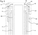
- Figure 2 shows a proximal section of a drug delivery device 1 comprising a feedback feature 2.
- the feedback feature 2 comprises a snap feature 35.
- the snap feature 35 is configured as a snap dome.
- the snap feature 35 comprises an opening 33, wherein the actuator 5 extends through the opening 33.
- a snap feature 35 is shown in Figure 3A .
- the snap feature 35 comprises or consists of a metal material.
- the snap feature 35 is configured as an arched disc.
- the snap feature 35 comprises at least one recess 34.
- the recess 34 is configured as a concave cavity.
- the snap feature 35 comprises four recesses 34. Due to the recesses 34, the snap feature 35 comprises a sufficient flexibility.
- the snap feature 35 is configured to snap through when it is compressed above a certain load. Thereby, the snap feature 35 creates an audible click. In particular, an audible and tactile feedback may be provided to a user at the end of a dispense operation.
- the snap feature 35 is configured as an arched disc which is free of any recess. Thereby, the snap feature 35 may comprise a high stiffness. Thereby, the feedback signal may be more distinct.
- the snap feature 35 is configured as an arched ring.
- the snap feature 35 comprises an opening.
- the snap feature 35 is operated by an axially moveable member 50 as shown in Figure 4 .
- the axially moveable member 50 is a sleeve member 24.
- the sleeve member 24 is arranged between the actuator 5 and the indicator 6.
- the sleeve member 24 can move axially relative to the actuator 5 between two stops 44, 45.
- the snap feature 35 pushes apart the actuator 5 and the sleeve member 24 to preload the sleeve member 24 against one of these stops 44, 45.
- one stop 44 is provided by the housing 3 and the other stop 45 is provided by the actuator 5.
- the sleeve member 24 contacts the stop 44 at the housing 3.
- the snap feature 35 When the actuator 5 is further moved towards its end position, the snap feature 35 is compressed. Thereby, the snap feature 35 is caused to snap, thereby creating an audible click.
- a clear audible and tactile feedback may be provided to a user at the end of a dispense operation. After a dispense operation, when the user releases the actuator 5, the snap feature 35 may relax to its un-compressed form. When the snap feature 35 relaxes, it may create a further audible and tactile feedback.
- the axially moveable member 50 in particular the sleeve member 24 comprises an enhancement feature 51.
- the enhancement feature 51 comprises a rigid section 37 and a flexible section 36.
- the rigid section 37 is arranged at a distal end of the sleeve member 24, and the flexible section 36 is arranged at a proximal end of the sleeve member 24.
- the flexible section 36 comprises at least one opening 38.
- the flexible section 36 comprises three openings 38.
- the flexible section 36 comprises at least one, in particular three flexible arms 41.
- the flexible arms 41 are configured to elastically deflect when a compressing force is exerted on the sleeve member 24 in an axial direction.
- the flexible arms 41 could extend radially inwards to use the internal volume of the sleeve member 24 more effectively.
- the sleeve member 24 is compressed when a force is exerted on the sleeve member 24 in axial direction. Thereby, the sleeve member 24 acts as a spring member.
- the flexible section 36 comprises a terminal ring 42.
- the terminal ring 42 connects the flexible arms 41.
- the terminal ring 42 comprises a contact face 43, which is configured to contact the snap feature 35, at least at the end of a dispense operation.
- the contact face 43 may comprise several points of contact with the snap feature. Thereby, a constraint on the vibration of the snap feature 35 may be reduced. Thereby, the audible and tactile feedback may be increased.
- the flexible arms 41 could be free-standing at the proximal end of the sleeve member 24. In this case, the contact surface 43 would be located at the free ends of the flexible arms 41.
- the sleeve member 24 contacts the stop 44 at the housing 3 when the actuator 5 approaches its end position during a dispense operation, in particular when the actuator 5 interacts with the feedback feature 2.
- the snap feature 35 and the flexible section 36 of the sleeve member 24 are compressed at the same time.
- the snap feature 35 is compressed above a certain load, its stiffness reduces rapidly. This will cause the flexible section 36 of the sleeve member 24 to expand rapidly and fully compress the snap feature 35. Thereby, the snap feature 35 is caused to snap, thereby creating an audible click.
- a clear audible and tactile feedback may be provided to a user at the end of a dispense operation.
- the tactile feedback comprises vibration and motion of the actuator 5, which is transmitted to a user, for example to a user's finger. Due to the low mass of the sleeve member 24 and the snap feature 35 and a relatively large amount of elastic energy stored within them, the resulting feedback may be louder and more energetic compared to an embodiment with a completely rigid sleeve member 24.
- the flexibility of the sleeve member 24 may also improve the strength of the feedback by reducing the stiffness of the contact constraints on the snap feature 35.
- the contact constraints on the snap feature 35 are the constraints which limit a movement or vibration of the snap feature 35. This may allow the snap feature 35 to vibrate with a larger amplitude and for a longer duration by reducing the energy transmission to the contact components, compared to an embodiment with a completely rigid sleeve member 24. This results in more energy transmission to the air and a louder feedback.
- the snap feature 35 When the load which is exerted on the snap feature 35 by the sleeve member 24 is released after a dispense operation, the snap feature 35 snaps back into its uncompressed form. Thereby, the snap feature 35 may create a further audible and tactile feedback. The sleeve member 24 also relaxes and turns back to its uncompressed form.
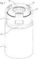
- Figure 5 shows a proximal part of a drug delivery device 1 comprising a different embodiment of a feedback feature 2.
- the actuator 5 comprises at least one, in particular three openings 39.
- the openings 39 are arranged at a proximal surface of the actuator 5.
- the feedback feature according to this embodiment comprises at least one tactile feature 40.
- the number of tactile features 40 corresponds to the number of openings 39 in the actuator.
- the tactile features 40 are configured as protrusions.
- the tactile features 40 are arranged at the axially moveable member 50, in particular at the sleeve member 24.
- the tactile features 40 may be an integral part of the sleeve member 24.
- the sleeve member 24 is a fully rigid member.
- the sleeve member 24 may comprise a flexible section and a rigid section, according to the sleeve member 24 described with reference to Figure 4 .
- the speed with which the tactile features 40 extend and hit the skin of a user may be increased.
- the tactile feedback may be strong and well-defined.
- Figure 6 shows a proximal part of the drug delivery device according to Figure 5 when the actuator 5 is actuated.
- the actuator 5 is in its end position after a dispense operation.
- the end position of the actuator 5 may be its most distal position.
- the actuator 5 is in its end position when it is fully depressed.
- the protrusions of the tactile features 40 are configured to move through the openings 39 of the actuator 5.
- the tactile features 40 protrude from the drug delivery device 1, in particular from the actuator 5.
- the tactile features 40 give a tactile feedback to a user at the end of a dispense operation.
- a user may feel the feedback feature 2 protruding from the actuator 5, for example with the thumb.
- FIG 7 shows a schematic view of a proximal part of a drug delivery device.
- the actuator 5 is shown transparent for a better understanding of the mechanism.
- the drug delivery device 1 comprises a snap feature 35, as described with reference to Figures 2 and 3 .
- the tactile features 40 extend through the recesses 34 of the snap feature 35.
- the actuator 5 rapidly moves in a direction towards the dispensing end of the device.
- the tactile features 40 rapidly protrude through the openings 39 provided by the actuator 5.
- the tactile features 40 directly impact on the skin of a user.
- a well defined tactile feedback is given to a user. This tactile feedback improves the clarity of a signal, especially in noisy environments or for users with hearing impairment.
Claims (15)
- Anordnung für eine Medikamenten-Verabreichungsvorrichtung, wobei die Anordnung (60) mindestens eine Feedbackfunktion (2) umfasst, die ausgestaltet ist, um ein Ende eines Abgabevorgangs an einen Anwender anzuzeigen, indem ein akustisches und/oder taktiles Feedback gegeben wird, und umfassend eine Erweiterungsfunktion (51), die ausgestaltet ist, um das Feedback der Feedbackfunktion (2) zu erweitern,
dadurch gekennzeichnet, dass
die mindestens eine Feedbackfunktion (2) mindestens eine Einrastfunktion (35) umfasst, die ausgestaltet ist, um durchzuschlagen, wenn sie über eine bestimmte Last hinaus komprimiert wird, um dadurch einem Anwender ein Feedback zu geben, und wobei die Feedbackfunktion (2) die Gestalt einer Kuppel oder die Gestalt einer gewölbten Scheibe umfasst. - Anordnung nach Anspruch 1, wobei die Erweiterungsfunktion eine Funktion zum Erhöhen der akustischen Wahrnehmung des akustischen Feedbacks und/oder zum Erhöhen der taktilen Wahrnehmung des taktilen Feedbacks ist.
- Anordnung nach einem der Ansprüche 1 oder 2, dadurch gekennzeichnet, dass die Anordnung ein Element umfasst, das ausgestaltet ist, um sich während einer Anfangsphase eines Abgabevorgangs axial zu bewegen, wobei die Erweiterungsfunktion einen flexiblen Abschnitt des axial beweglichen Elements umfasst.
- Anordnung nach einem der Ansprüche 1 bis 3, umfassend einen Aktor (5), der ausgestaltet ist, um so betrieben zu werden, dass eine Dosis abgegeben wird, und wobei ein Feedback erzeugt wird, wenn der Aktor (5) eine Endposition am Ende eines Abgabevorgangs erreicht.
- Anordnung nach Anspruch 4, wobei die Feedbackfunktion (2) eine Einrastfunktion umfasst, die eine Öffnung umfasst, wobei der Aktor (5) sich durch die Öffnung hindurch erstreckt.
- Anordnung nach einem der vorhergehenden Ansprüche, umfassend ein Element (50), das ausgestaltet ist, um mit der Feedbackfunktion (2) zu interagieren.
- Anordnung nach Anspruch 6, wobei das Element (50) ausgestaltet ist, um in einer axialen Richtung zu expandieren, wenn die Einrastfunktion (35) durchschlägt.
- Anordnung nach einem der Ansprüche 6 bis 7, wobei das Element (50) einen starren Abschnitt und einen flexiblen Abschnitt umfasst.
- Anordnung nach einem der vorhergehenden Ansprüche, wobei die mindestens eine Feedbackfunktion (2) ein Metallmaterial umfasst.
- Anordnung nach einem der vorhergehenden Ansprüche, wobei die mindestens eine Feedbackfunktion (2) mindestens eine taktile Funktion (40) umfasst, die ausgestaltet ist, um einem Anwender am Ende eines Abgabevorgangs ein taktiles Feedback zu geben.
- Anordnung nach Anspruch 10, umfassend einen Aktor (5), der ausgestaltet ist, um betätigt zu werden, um eine Medikamentendosis abzugeben, wobei die mindestens eine taktile Funktion (40) so ausgestaltet ist, dass sie am Ende eines Abgabevorgangs aus dem Aktor (5) hervorragt.
- Anordnung nach einem der Ansprüche 10 oder 11, wobei die mindestens eine taktile Funktion (40) so ausgestaltet ist, dass sie durch eine Öffnung (39) in dem Aktor (5) hervorragt.
- Anordnung nach einem der Ansprüche 10 bis 12, umfassend die Einrastfunktion (35), wobei die mindestens eine taktile Funktion (40) herausspringt, wenn die Einrastfunktion (35) durchschlägt.
- Anordnung nach einem der Ansprüche 10 bis 13, umfassend ein Element (50), wobei die mindestens eine taktile Funktion (40) an dem Element (50) befestigt ist, und wobei die mindestens eine taktile Funktion (40) sich von dem Element (50) aus in eine proximale Richtung erstreckt.
- Medikamenten-Verabreichungsvorrichtung, die die Anordnung nach einem der Ansprüche 1 bis 14 umfasst.
Priority Applications (1)
| Application Number | Priority Date | Filing Date | Title |
|---|---|---|---|
| EP14708566.6A EP2968786B1 (de) | 2013-03-13 | 2014-03-10 | Anordnung für eine arzneimittelabgabevorrichtung mit einer feedbackfunktion |
Applications Claiming Priority (3)
| Application Number | Priority Date | Filing Date | Title |
|---|---|---|---|
| EP13159057 | 2013-03-13 | ||
| EP14708566.6A EP2968786B1 (de) | 2013-03-13 | 2014-03-10 | Anordnung für eine arzneimittelabgabevorrichtung mit einer feedbackfunktion |
| PCT/EP2014/054535 WO2014139922A1 (en) | 2013-03-13 | 2014-03-10 | Assembly for a drug delivery device comprising a feedback feature |
Publications (2)
| Publication Number | Publication Date |
|---|---|
| EP2968786A1 EP2968786A1 (de) | 2016-01-20 |
| EP2968786B1 true EP2968786B1 (de) | 2020-09-23 |
Family
ID=47891454
Family Applications (1)
| Application Number | Title | Priority Date | Filing Date |
|---|---|---|---|
| EP14708566.6A Active EP2968786B1 (de) | 2013-03-13 | 2014-03-10 | Anordnung für eine arzneimittelabgabevorrichtung mit einer feedbackfunktion |
Country Status (7)
| Country | Link |
|---|---|
| US (1) | US10406293B2 (de) |
| EP (1) | EP2968786B1 (de) |
| JP (1) | JP6480350B2 (de) |
| CN (1) | CN105188809B (de) |
| DK (1) | DK2968786T3 (de) |
| HK (1) | HK1213513A1 (de) |
| WO (1) | WO2014139922A1 (de) |
Families Citing this family (6)
| Publication number | Priority date | Publication date | Assignee | Title |
|---|---|---|---|---|
| TW201709941A (zh) | 2015-06-03 | 2017-03-16 | 賽諾菲阿凡提斯德意志有限公司 | 聲響指示器(二) |
| TW201709940A (zh) | 2015-06-03 | 2017-03-16 | 賽諾菲阿凡提斯德意志有限公司 | 聲響指示器(一) |
| TW201711713A (zh) | 2015-06-03 | 2017-04-01 | 賽諾菲阿凡提斯德意志有限公司 | 藥物輸送裝置(五) |
| TW201707737A (zh) | 2015-06-03 | 2017-03-01 | 賽諾菲阿凡提斯德意志有限公司 | 藥物輸送裝置(一) |
| US11400232B2 (en) | 2017-11-03 | 2022-08-02 | Sanofi | Drug delivery device |
| CN111587132B (zh) | 2017-11-03 | 2022-10-04 | 赛诺菲 | 药物递送装置 |
Citations (2)
| Publication number | Priority date | Publication date | Assignee | Title |
|---|---|---|---|---|
| US20090012479A1 (en) * | 2005-01-25 | 2009-01-08 | Novo Nordisk A/S | Injection Device with an End of Dose Feedback Mechanism |
| WO2012085584A2 (en) * | 2010-12-22 | 2012-06-28 | Owen Mumford Limited | Autoinjectors |
Family Cites Families (67)
| Publication number | Priority date | Publication date | Assignee | Title |
|---|---|---|---|---|
| US533575A (en) | 1895-02-05 | wilkens | ||
| US4201209A (en) * | 1978-05-24 | 1980-05-06 | Leveen Harry H | Molded hypodermic plunger with integral shaft and elastomeric head |
| DE3715258C2 (de) | 1987-05-08 | 1996-10-31 | Haselmeier Wilhelm Fa | Injektionsgerät |
| GB8713810D0 (en) | 1987-06-12 | 1987-07-15 | Hypoguard Uk Ltd | Measured dose dispensing device |
| US5226895A (en) | 1989-06-05 | 1993-07-13 | Eli Lilly And Company | Multiple dose injection pen |
| GB9007113D0 (en) | 1990-03-29 | 1990-05-30 | Sams Bernard | Dispensing device |
| US5226896A (en) | 1990-04-04 | 1993-07-13 | Eli Lilly And Company | Dose indicating injection pen |
| AU641206B2 (en) | 1991-01-22 | 1993-09-16 | Eli Lilly And Company | Multiple dose injection pen |
| ATE121953T1 (de) | 1991-07-24 | 1995-05-15 | Medico Dev Investment Co | Injektor. |
| DK175491D0 (da) | 1991-10-18 | 1991-10-18 | Novo Nordisk As | Apparat |
| US5279585A (en) | 1992-02-04 | 1994-01-18 | Becton, Dickinson And Company | Medication delivery pen having improved dose delivery features |
| US5271527A (en) | 1992-04-02 | 1993-12-21 | Habley Medical Technology Corporation | Reusable pharmaceutical dispenser with full stroke indicator |
| US5300041A (en) | 1992-06-01 | 1994-04-05 | Habley Medical Technology Corporation | Dose setting and repeating syringe |
| US5391157A (en) * | 1992-10-20 | 1995-02-21 | Eli Lilly And Company | End of dose indicator |
| US5378233A (en) | 1992-11-18 | 1995-01-03 | Habley Medical Technology Corporation | Selected dose pharmaceutical dispenser |
| US5320609A (en) | 1992-12-07 | 1994-06-14 | Habley Medical Technology Corporation | Automatic pharmaceutical dispensing syringe |
| FR2701211B1 (fr) | 1993-02-08 | 1995-05-24 | Aguettant Lab | Instrument doseur, notamment d'injection |
| US5383865A (en) | 1993-03-15 | 1995-01-24 | Eli Lilly And Company | Medication dispensing device |
| ZA941881B (en) | 1993-04-02 | 1995-09-18 | Lilly Co Eli | Manifold medication injection apparatus and method |
| US5582598A (en) | 1994-09-19 | 1996-12-10 | Becton Dickinson And Company | Medication delivery pen with variable increment dose scale |
| WO1996027400A1 (en) | 1995-03-07 | 1996-09-12 | Eli Lilly And Company | Recyclable medication dispensing device |
| AU1860697A (en) | 1995-09-08 | 1997-07-28 | Visionary Medical Products Corporation | Pen-type injector drive mechanism |
| US5688251A (en) | 1995-09-19 | 1997-11-18 | Becton Dickinson And Company | Cartridge loading and priming mechanism for a pen injector |
| US5674204A (en) | 1995-09-19 | 1997-10-07 | Becton Dickinson And Company | Medication delivery pen cap actuated dose delivery clutch |
| US5851079A (en) | 1996-10-25 | 1998-12-22 | The Procter & Gamble Company | Simplified undirectional twist-up dispensing device with incremental dosing |
| DE19730999C1 (de) | 1997-07-18 | 1998-12-10 | Disetronic Licensing Ag | Dosierknopfsicherung an einer Vorrichtung zur dosierten Verabreichung eines injizierbaren Produkts |
| US5957896A (en) | 1997-08-11 | 1999-09-28 | Becton, Dickinson And Company | Medication delivery pen |
| US6786330B2 (en) * | 1997-10-14 | 2004-09-07 | Biogaia Ab | Two-compartment container |
| PL191327B1 (pl) | 1998-01-30 | 2006-04-28 | Novo Nordisk As | Strzykawka do podawania ustalonych dawek lekarstwa z naboju |
| US6096010A (en) * | 1998-02-20 | 2000-08-01 | Becton, Dickinson And Company | Repeat-dose medication delivery pen |
| US6221053B1 (en) | 1998-02-20 | 2001-04-24 | Becton, Dickinson And Company | Multi-featured medication delivery pen |
| US6248095B1 (en) | 1998-02-23 | 2001-06-19 | Becton, Dickinson And Company | Low-cost medication delivery pen |
| DE19900827C1 (de) | 1999-01-12 | 2000-08-17 | Disetronic Licensing Ag | Vorrichtung zur dosierten Verabreichung eines injizierbaren Produkts |
| DE19900792C1 (de) | 1999-01-12 | 2000-06-15 | Disetronic Licensing Ag | Vorrichtung zur Verabreichung eines injizierbaren Produkts |
| DE29900482U1 (de) | 1999-01-14 | 2000-08-31 | Medico Dev Investment Co | Injektionsgerät |
| SE9901366D0 (sv) | 1999-04-16 | 1999-04-16 | Pharmacia & Upjohn Ab | Injector device and method for its operation |
| WO2001010484A1 (en) | 1999-08-05 | 2001-02-15 | Becton, Dickinson And Company | Medication delivery pen |
| GB0007071D0 (en) | 2000-03-24 | 2000-05-17 | Sams Bernard | One-way clutch mechanisms and injector devices |
| US6663602B2 (en) | 2000-06-16 | 2003-12-16 | Novo Nordisk A/S | Injection device |
| JP2002056678A (ja) * | 2000-08-14 | 2002-02-22 | Mitsubishi Electric Corp | 基板バイアス電圧発生回路 |
| NZ539404A (en) | 2000-10-09 | 2007-05-31 | Lilly Co Eli | Pen device for administration of parathyroid hormone |
| US6899699B2 (en) | 2001-01-05 | 2005-05-31 | Novo Nordisk A/S | Automatic injection device with reset feature |
| EP2258424B1 (de) | 2001-05-16 | 2013-01-30 | Eli Lilly and Company | Spritzvorrichtung |
| AU2003216521A1 (en) | 2002-03-18 | 2003-10-08 | Eli Lilly And Company | Medication dispensing apparatus with gear set for mechanical advantage |
| AU2003275353A1 (en) | 2002-10-01 | 2004-04-23 | Becton, Dickinson And Company | Medication delivery pen |
| GB0304822D0 (en) | 2003-03-03 | 2003-04-09 | Dca Internat Ltd | Improvements in and relating to a pen-type injector |
| GB0304823D0 (en) | 2003-03-03 | 2003-04-09 | Dca Internat Ltd | Improvements in and relating to a pen-type injector |
| US6932794B2 (en) | 2003-04-03 | 2005-08-23 | Becton, Dickinson And Company | Medication delivery pen |
| ES2721548T3 (es) | 2003-08-12 | 2019-08-01 | Lilly Co Eli | Aparato de dispensado de medicamentos con roscas de tornillo triples para una ventaja mecánica |
| EP1541185A1 (de) | 2003-12-08 | 2005-06-15 | Novo Nordisk A/S | Automatische Spritze mit Vorfüllmechanismus |
| WO2006052827A2 (en) * | 2004-11-04 | 2006-05-18 | Viz Enterprises, Llc | Multi-chamber container and cap therefor |
| DE102004063645A1 (de) | 2004-12-31 | 2006-07-20 | Tecpharma Licensing Ag | Vorrichtung zur dosierten Verabreichung eines fluiden Produkts mit Entkopplung für einen Behältniswechsel |
| WO2006084876A1 (en) | 2005-02-11 | 2006-08-17 | Novo Nordisk A/S | Injection device |
| JP2008142502A (ja) | 2006-12-11 | 2008-06-26 | Naoki Takebe | 健康用具 |
| JP4281804B2 (ja) * | 2007-01-25 | 2009-06-17 | トヨタ自動車株式会社 | 内燃機関の排気浄化システム |
| US8267901B2 (en) * | 2007-09-25 | 2012-09-18 | Claus Schmidt Moller | Dose delivery device with gearing mechanism |
| US8647309B2 (en) | 2008-05-02 | 2014-02-11 | Sanofi-Aventis Deutschland Gmbh | Medication delivery device |
| GB2461697A (en) * | 2008-07-07 | 2010-01-13 | Sony Uk Ltd | Television with Audio Descriptor Mode Activated by Tactile Region |
| US10286150B2 (en) * | 2009-03-31 | 2019-05-14 | Michael Harms | Dose button for a drug delivery device and method for manufacturing a dose button |
| KR101027514B1 (ko) | 2009-06-15 | 2011-04-06 | 삼성전기주식회사 | 입력 장치 |
| CN101963681B (zh) * | 2009-07-24 | 2012-06-20 | 清华大学 | 偏光元件 |
| EP3023114A1 (de) | 2009-10-08 | 2016-05-25 | SHL Group AB | Medikamentenabgabevorrichtung |
| AU2010306625B2 (en) | 2009-10-16 | 2015-01-22 | Janssen Biotech Inc. | Palm activated drug delivery device |
| US8811513B2 (en) * | 2010-02-05 | 2014-08-19 | Qualcomm Incorporated | Antenna switching in a closed loop transmit diversity system |
| EP2489384A1 (de) | 2011-02-18 | 2012-08-22 | Sanofi-Aventis Deutschland GmbH | Automatischer Injektor |
| BR112013023840B1 (pt) * | 2011-03-18 | 2021-05-04 | Becton, Dikinson And Company | caneta de injeção de medicamento |
| WO2012154362A1 (en) * | 2011-04-11 | 2012-11-15 | Seventh Sense Biosysems, Inc. | Devices and methods for delivery and/or withdrawal of fluids and preservation of withdrawn fluids |
-
2014
- 2014-03-10 JP JP2015562064A patent/JP6480350B2/ja active Active
- 2014-03-10 CN CN201480013766.1A patent/CN105188809B/zh active Active
- 2014-03-10 EP EP14708566.6A patent/EP2968786B1/de active Active
- 2014-03-10 WO PCT/EP2014/054535 patent/WO2014139922A1/en active Application Filing
- 2014-03-10 DK DK14708566.6T patent/DK2968786T3/da active
- 2014-03-10 US US14/774,692 patent/US10406293B2/en active Active
-
2016
- 2016-02-11 HK HK16101482.5A patent/HK1213513A1/zh unknown
Patent Citations (2)
| Publication number | Priority date | Publication date | Assignee | Title |
|---|---|---|---|---|
| US20090012479A1 (en) * | 2005-01-25 | 2009-01-08 | Novo Nordisk A/S | Injection Device with an End of Dose Feedback Mechanism |
| WO2012085584A2 (en) * | 2010-12-22 | 2012-06-28 | Owen Mumford Limited | Autoinjectors |
Also Published As
| Publication number | Publication date |
|---|---|
| JP2016513507A (ja) | 2016-05-16 |
| JP6480350B2 (ja) | 2019-03-06 |
| WO2014139922A1 (en) | 2014-09-18 |
| US10406293B2 (en) | 2019-09-10 |
| CN105188809A (zh) | 2015-12-23 |
| US20160030675A1 (en) | 2016-02-04 |
| HK1213513A1 (zh) | 2016-07-08 |
| CN105188809B (zh) | 2019-02-15 |
| DK2968786T3 (da) | 2020-12-14 |
| EP2968786A1 (de) | 2016-01-20 |
Similar Documents
| Publication | Publication Date | Title |
|---|---|---|
| US11654245B2 (en) | Assembly for a drug delivery device comprising a feedback feature | |
| EP2968784B1 (de) | Anordnung für eine arzneimittelabgabevorrichtung mit einer rückmeldungsfunktion | |
| EP3003432B1 (de) | Ansteuerungsanordnung für eine wirkstofffreisetzungsvorrichtung und wirkstofffreisetzungsvorrichtung | |
| EP2968786B1 (de) | Anordnung für eine arzneimittelabgabevorrichtung mit einer feedbackfunktion | |
| EP2996743B1 (de) | Anordnung für eine wirkstofffreisetzungsvorrichtung und wirkstofffreisetzungsvorrichtung | |
| EP2895218B1 (de) | Antriebsmechanismus für eine arzneimittelabgabevorrichtung und arzneimittelabgabevorrichtung | |
| EP2916890B1 (de) | Dosiseinstellmechanismus für eine arzneimittelabgabevorrichtung | |
| EP2654858B1 (de) | Injektionsgerät mit dosiermechanismus mit maximaldosisbegrenzung | |
| US10420890B2 (en) | Assembly for a drug delivery device and use of an attenuation member | |
| EP3003439B1 (de) | Anordnung für eine wirkstofffreisetzungsvorrichtung und wirkstofffreisetzungsvorrichtung | |
| US20160206824A1 (en) | Assembly for a drug delivery device | |
| EP2950857B1 (de) | Anordnung für eine arzneimittelverabreichungsvorrichtung |
Legal Events
| Date | Code | Title | Description |
|---|---|---|---|
| PUAI | Public reference made under article 153(3) epc to a published international application that has entered the european phase |
Free format text: ORIGINAL CODE: 0009012 |
|
| 17P | Request for examination filed |
Effective date: 20151013 |
|
| AK | Designated contracting states |
Kind code of ref document: A1 Designated state(s): AL AT BE BG CH CY CZ DE DK EE ES FI FR GB GR HR HU IE IS IT LI LT LU LV MC MK MT NL NO PL PT RO RS SE SI SK SM TR |
|
| AX | Request for extension of the european patent |
Extension state: BA ME |
|
| DAX | Request for extension of the european patent (deleted) | ||
| REG | Reference to a national code |
Ref country code: HK Ref legal event code: DE Ref document number: 1213513 Country of ref document: HK |
|
| TPAC | Observations filed by third parties |
Free format text: ORIGINAL CODE: EPIDOSNTIPA |
|
| STAA | Information on the status of an ep patent application or granted ep patent |
Free format text: STATUS: EXAMINATION IS IN PROGRESS |
|
| 17Q | First examination report despatched |
Effective date: 20181025 |
|
| GRAP | Despatch of communication of intention to grant a patent |
Free format text: ORIGINAL CODE: EPIDOSNIGR1 |
|
| STAA | Information on the status of an ep patent application or granted ep patent |
Free format text: STATUS: GRANT OF PATENT IS INTENDED |
|
| INTG | Intention to grant announced |
Effective date: 20200519 |
|
| GRAS | Grant fee paid |
Free format text: ORIGINAL CODE: EPIDOSNIGR3 |
|
| GRAA | (expected) grant |
Free format text: ORIGINAL CODE: 0009210 |
|
| STAA | Information on the status of an ep patent application or granted ep patent |
Free format text: STATUS: THE PATENT HAS BEEN GRANTED |
|
| AK | Designated contracting states |
Kind code of ref document: B1 Designated state(s): AL AT BE BG CH CY CZ DE DK EE ES FI FR GB GR HR HU IE IS IT LI LT LU LV MC MK MT NL NO PL PT RO RS SE SI SK SM TR |
|
| REG | Reference to a national code |
Ref country code: GB Ref legal event code: FG4D |
|
| REG | Reference to a national code |
Ref country code: CH Ref legal event code: EP |
|
| REG | Reference to a national code |
Ref country code: IE Ref legal event code: FG4D |
|
| REG | Reference to a national code |
Ref country code: DE Ref legal event code: R096 Ref document number: 602014070443 Country of ref document: DE Ref country code: AT Ref legal event code: REF Ref document number: 1315760 Country of ref document: AT Kind code of ref document: T Effective date: 20201015 |
|
| REG | Reference to a national code |
Ref country code: DK Ref legal event code: T3 Effective date: 20201209 |
|
| PG25 | Lapsed in a contracting state [announced via postgrant information from national office to epo] |
Ref country code: NO Free format text: LAPSE BECAUSE OF FAILURE TO SUBMIT A TRANSLATION OF THE DESCRIPTION OR TO PAY THE FEE WITHIN THE PRESCRIBED TIME-LIMIT Effective date: 20201223 Ref country code: SE Free format text: LAPSE BECAUSE OF FAILURE TO SUBMIT A TRANSLATION OF THE DESCRIPTION OR TO PAY THE FEE WITHIN THE PRESCRIBED TIME-LIMIT Effective date: 20200923 Ref country code: GR Free format text: LAPSE BECAUSE OF FAILURE TO SUBMIT A TRANSLATION OF THE DESCRIPTION OR TO PAY THE FEE WITHIN THE PRESCRIBED TIME-LIMIT Effective date: 20201224 Ref country code: FI Free format text: LAPSE BECAUSE OF FAILURE TO SUBMIT A TRANSLATION OF THE DESCRIPTION OR TO PAY THE FEE WITHIN THE PRESCRIBED TIME-LIMIT Effective date: 20200923 Ref country code: HR Free format text: LAPSE BECAUSE OF FAILURE TO SUBMIT A TRANSLATION OF THE DESCRIPTION OR TO PAY THE FEE WITHIN THE PRESCRIBED TIME-LIMIT Effective date: 20200923 Ref country code: BG Free format text: LAPSE BECAUSE OF FAILURE TO SUBMIT A TRANSLATION OF THE DESCRIPTION OR TO PAY THE FEE WITHIN THE PRESCRIBED TIME-LIMIT Effective date: 20201223 |
|
| REG | Reference to a national code |
Ref country code: AT Ref legal event code: MK05 Ref document number: 1315760 Country of ref document: AT Kind code of ref document: T Effective date: 20200923 |
|
| PG25 | Lapsed in a contracting state [announced via postgrant information from national office to epo] |
Ref country code: LV Free format text: LAPSE BECAUSE OF FAILURE TO SUBMIT A TRANSLATION OF THE DESCRIPTION OR TO PAY THE FEE WITHIN THE PRESCRIBED TIME-LIMIT Effective date: 20200923 Ref country code: RS Free format text: LAPSE BECAUSE OF FAILURE TO SUBMIT A TRANSLATION OF THE DESCRIPTION OR TO PAY THE FEE WITHIN THE PRESCRIBED TIME-LIMIT Effective date: 20200923 |
|
| REG | Reference to a national code |
Ref country code: NL Ref legal event code: MP Effective date: 20200923 |
|
| REG | Reference to a national code |
Ref country code: LT Ref legal event code: MG4D |
|
| PG25 | Lapsed in a contracting state [announced via postgrant information from national office to epo] |
Ref country code: CZ Free format text: LAPSE BECAUSE OF FAILURE TO SUBMIT A TRANSLATION OF THE DESCRIPTION OR TO PAY THE FEE WITHIN THE PRESCRIBED TIME-LIMIT Effective date: 20200923 Ref country code: EE Free format text: LAPSE BECAUSE OF FAILURE TO SUBMIT A TRANSLATION OF THE DESCRIPTION OR TO PAY THE FEE WITHIN THE PRESCRIBED TIME-LIMIT Effective date: 20200923 Ref country code: LT Free format text: LAPSE BECAUSE OF FAILURE TO SUBMIT A TRANSLATION OF THE DESCRIPTION OR TO PAY THE FEE WITHIN THE PRESCRIBED TIME-LIMIT Effective date: 20200923 Ref country code: PT Free format text: LAPSE BECAUSE OF FAILURE TO SUBMIT A TRANSLATION OF THE DESCRIPTION OR TO PAY THE FEE WITHIN THE PRESCRIBED TIME-LIMIT Effective date: 20210125 Ref country code: NL Free format text: LAPSE BECAUSE OF FAILURE TO SUBMIT A TRANSLATION OF THE DESCRIPTION OR TO PAY THE FEE WITHIN THE PRESCRIBED TIME-LIMIT Effective date: 20200923 Ref country code: SM Free format text: LAPSE BECAUSE OF FAILURE TO SUBMIT A TRANSLATION OF THE DESCRIPTION OR TO PAY THE FEE WITHIN THE PRESCRIBED TIME-LIMIT Effective date: 20200923 Ref country code: RO Free format text: LAPSE BECAUSE OF FAILURE TO SUBMIT A TRANSLATION OF THE DESCRIPTION OR TO PAY THE FEE WITHIN THE PRESCRIBED TIME-LIMIT Effective date: 20200923 |
|
| PG25 | Lapsed in a contracting state [announced via postgrant information from national office to epo] |
Ref country code: AL Free format text: LAPSE BECAUSE OF FAILURE TO SUBMIT A TRANSLATION OF THE DESCRIPTION OR TO PAY THE FEE WITHIN THE PRESCRIBED TIME-LIMIT Effective date: 20200923 Ref country code: AT Free format text: LAPSE BECAUSE OF FAILURE TO SUBMIT A TRANSLATION OF THE DESCRIPTION OR TO PAY THE FEE WITHIN THE PRESCRIBED TIME-LIMIT Effective date: 20200923 Ref country code: ES Free format text: LAPSE BECAUSE OF FAILURE TO SUBMIT A TRANSLATION OF THE DESCRIPTION OR TO PAY THE FEE WITHIN THE PRESCRIBED TIME-LIMIT Effective date: 20200923 Ref country code: PL Free format text: LAPSE BECAUSE OF FAILURE TO SUBMIT A TRANSLATION OF THE DESCRIPTION OR TO PAY THE FEE WITHIN THE PRESCRIBED TIME-LIMIT Effective date: 20200923 Ref country code: IS Free format text: LAPSE BECAUSE OF FAILURE TO SUBMIT A TRANSLATION OF THE DESCRIPTION OR TO PAY THE FEE WITHIN THE PRESCRIBED TIME-LIMIT Effective date: 20210123 |
|
| REG | Reference to a national code |
Ref country code: DE Ref legal event code: R097 Ref document number: 602014070443 Country of ref document: DE |
|
| PG25 | Lapsed in a contracting state [announced via postgrant information from national office to epo] |
Ref country code: SK Free format text: LAPSE BECAUSE OF FAILURE TO SUBMIT A TRANSLATION OF THE DESCRIPTION OR TO PAY THE FEE WITHIN THE PRESCRIBED TIME-LIMIT Effective date: 20200923 |
|
| PLBE | No opposition filed within time limit |
Free format text: ORIGINAL CODE: 0009261 |
|
| STAA | Information on the status of an ep patent application or granted ep patent |
Free format text: STATUS: NO OPPOSITION FILED WITHIN TIME LIMIT |
|
| PG25 | Lapsed in a contracting state [announced via postgrant information from national office to epo] |
Ref country code: SI Free format text: LAPSE BECAUSE OF FAILURE TO SUBMIT A TRANSLATION OF THE DESCRIPTION OR TO PAY THE FEE WITHIN THE PRESCRIBED TIME-LIMIT Effective date: 20200923 |
|
| 26N | No opposition filed |
Effective date: 20210624 |
|
| PG25 | Lapsed in a contracting state [announced via postgrant information from national office to epo] |
Ref country code: IT Free format text: LAPSE BECAUSE OF FAILURE TO SUBMIT A TRANSLATION OF THE DESCRIPTION OR TO PAY THE FEE WITHIN THE PRESCRIBED TIME-LIMIT Effective date: 20200923 Ref country code: MC Free format text: LAPSE BECAUSE OF FAILURE TO SUBMIT A TRANSLATION OF THE DESCRIPTION OR TO PAY THE FEE WITHIN THE PRESCRIBED TIME-LIMIT Effective date: 20200923 |
|
| REG | Reference to a national code |
Ref country code: BE Ref legal event code: MM Effective date: 20210331 |
|
| PG25 | Lapsed in a contracting state [announced via postgrant information from national office to epo] |
Ref country code: LU Free format text: LAPSE BECAUSE OF NON-PAYMENT OF DUE FEES Effective date: 20210310 Ref country code: IE Free format text: LAPSE BECAUSE OF NON-PAYMENT OF DUE FEES Effective date: 20210310 |
|
| PG25 | Lapsed in a contracting state [announced via postgrant information from national office to epo] |
Ref country code: BE Free format text: LAPSE BECAUSE OF NON-PAYMENT OF DUE FEES Effective date: 20210331 |
|
| PGFP | Annual fee paid to national office [announced via postgrant information from national office to epo] |
Ref country code: FR Payment date: 20230110 Year of fee payment: 10 Ref country code: DK Payment date: 20230314 Year of fee payment: 10 |
|
| PG25 | Lapsed in a contracting state [announced via postgrant information from national office to epo] |
Ref country code: HU Free format text: LAPSE BECAUSE OF FAILURE TO SUBMIT A TRANSLATION OF THE DESCRIPTION OR TO PAY THE FEE WITHIN THE PRESCRIBED TIME-LIMIT; INVALID AB INITIO Effective date: 20140310 |
|
| PGFP | Annual fee paid to national office [announced via postgrant information from national office to epo] |
Ref country code: TR Payment date: 20230309 Year of fee payment: 10 Ref country code: GB Payment date: 20230119 Year of fee payment: 10 Ref country code: DE Payment date: 20230110 Year of fee payment: 10 |
|
| P01 | Opt-out of the competence of the unified patent court (upc) registered |
Effective date: 20230421 |
|
| PG25 | Lapsed in a contracting state [announced via postgrant information from national office to epo] |
Ref country code: CY Free format text: LAPSE BECAUSE OF FAILURE TO SUBMIT A TRANSLATION OF THE DESCRIPTION OR TO PAY THE FEE WITHIN THE PRESCRIBED TIME-LIMIT Effective date: 20200923 |
|
| PGFP | Annual fee paid to national office [announced via postgrant information from national office to epo] |
Ref country code: CH Payment date: 20230401 Year of fee payment: 10 |