EP4527424A2 - Dialysetransferset mit filterintegritätsprüfung - Google Patents
Dialysetransferset mit filterintegritätsprüfung Download PDFInfo
- Publication number
- EP4527424A2 EP4527424A2 EP25156935.6A EP25156935A EP4527424A2 EP 4527424 A2 EP4527424 A2 EP 4527424A2 EP 25156935 A EP25156935 A EP 25156935A EP 4527424 A2 EP4527424 A2 EP 4527424A2
- Authority
- EP
- European Patent Office
- Prior art keywords
- filter
- water
- line
- pumping portion
- fluid communication
- Prior art date
- Legal status (The legal status is an assumption and is not a legal conclusion. Google has not performed a legal analysis and makes no representation as to the accuracy of the status listed.)
- Pending
Links
Images


Classifications
-
- A—HUMAN NECESSITIES
- A61—MEDICAL OR VETERINARY SCIENCE; HYGIENE
- A61M—DEVICES FOR INTRODUCING MEDIA INTO, OR ONTO, THE BODY; DEVICES FOR TRANSDUCING BODY MEDIA OR FOR TAKING MEDIA FROM THE BODY; DEVICES FOR PRODUCING OR ENDING SLEEP OR STUPOR
- A61M1/00—Suction or pumping devices for medical purposes; Devices for carrying-off, for treatment of, or for carrying-over, body-liquids; Drainage systems
- A61M1/14—Dialysis systems; Artificial kidneys; Blood oxygenators ; Reciprocating systems for treatment of body fluids, e.g. single needle systems for hemofiltration or pheresis
- A61M1/16—Dialysis systems; Artificial kidneys; Blood oxygenators ; Reciprocating systems for treatment of body fluids, e.g. single needle systems for hemofiltration or pheresis with membranes
- A61M1/1654—Dialysates therefor
- A61M1/1656—Apparatus for preparing dialysates
- A61M1/1672—Apparatus for preparing dialysates using membrane filters, e.g. for sterilising the dialysate
-
- A—HUMAN NECESSITIES
- A61—MEDICAL OR VETERINARY SCIENCE; HYGIENE
- A61M—DEVICES FOR INTRODUCING MEDIA INTO, OR ONTO, THE BODY; DEVICES FOR TRANSDUCING BODY MEDIA OR FOR TAKING MEDIA FROM THE BODY; DEVICES FOR PRODUCING OR ENDING SLEEP OR STUPOR
- A61M1/00—Suction or pumping devices for medical purposes; Devices for carrying-off, for treatment of, or for carrying-over, body-liquids; Drainage systems
- A61M1/14—Dialysis systems; Artificial kidneys; Blood oxygenators ; Reciprocating systems for treatment of body fluids, e.g. single needle systems for hemofiltration or pheresis
- A61M1/15—Dialysis systems; Artificial kidneys; Blood oxygenators ; Reciprocating systems for treatment of body fluids, e.g. single needle systems for hemofiltration or pheresis with a cassette forming partially or totally the flow circuit for the treating fluid, e.g. the dialysate fluid circuit or the treating gas circuit
- A61M1/155—Dialysis systems; Artificial kidneys; Blood oxygenators ; Reciprocating systems for treatment of body fluids, e.g. single needle systems for hemofiltration or pheresis with a cassette forming partially or totally the flow circuit for the treating fluid, e.g. the dialysate fluid circuit or the treating gas circuit with treatment-fluid pumping means or components thereof
-
- A—HUMAN NECESSITIES
- A61—MEDICAL OR VETERINARY SCIENCE; HYGIENE
- A61M—DEVICES FOR INTRODUCING MEDIA INTO, OR ONTO, THE BODY; DEVICES FOR TRANSDUCING BODY MEDIA OR FOR TAKING MEDIA FROM THE BODY; DEVICES FOR PRODUCING OR ENDING SLEEP OR STUPOR
- A61M1/00—Suction or pumping devices for medical purposes; Devices for carrying-off, for treatment of, or for carrying-over, body-liquids; Drainage systems
- A61M1/14—Dialysis systems; Artificial kidneys; Blood oxygenators ; Reciprocating systems for treatment of body fluids, e.g. single needle systems for hemofiltration or pheresis
- A61M1/15—Dialysis systems; Artificial kidneys; Blood oxygenators ; Reciprocating systems for treatment of body fluids, e.g. single needle systems for hemofiltration or pheresis with a cassette forming partially or totally the flow circuit for the treating fluid, e.g. the dialysate fluid circuit or the treating gas circuit
- A61M1/156—Constructional details of the cassette, e.g. specific details on material or shape
- A61M1/1561—Constructional details of the cassette, e.g. specific details on material or shape at least one cassette surface or portion thereof being flexible, e.g. the cassette having a rigid base portion with preformed channels and being covered with a foil
-
- A—HUMAN NECESSITIES
- A61—MEDICAL OR VETERINARY SCIENCE; HYGIENE
- A61M—DEVICES FOR INTRODUCING MEDIA INTO, OR ONTO, THE BODY; DEVICES FOR TRANSDUCING BODY MEDIA OR FOR TAKING MEDIA FROM THE BODY; DEVICES FOR PRODUCING OR ENDING SLEEP OR STUPOR
- A61M1/00—Suction or pumping devices for medical purposes; Devices for carrying-off, for treatment of, or for carrying-over, body-liquids; Drainage systems
- A61M1/14—Dialysis systems; Artificial kidneys; Blood oxygenators ; Reciprocating systems for treatment of body fluids, e.g. single needle systems for hemofiltration or pheresis
- A61M1/15—Dialysis systems; Artificial kidneys; Blood oxygenators ; Reciprocating systems for treatment of body fluids, e.g. single needle systems for hemofiltration or pheresis with a cassette forming partially or totally the flow circuit for the treating fluid, e.g. the dialysate fluid circuit or the treating gas circuit
- A61M1/156—Constructional details of the cassette, e.g. specific details on material or shape
- A61M1/1565—Details of valves
-
- A—HUMAN NECESSITIES
- A61—MEDICAL OR VETERINARY SCIENCE; HYGIENE
- A61M—DEVICES FOR INTRODUCING MEDIA INTO, OR ONTO, THE BODY; DEVICES FOR TRANSDUCING BODY MEDIA OR FOR TAKING MEDIA FROM THE BODY; DEVICES FOR PRODUCING OR ENDING SLEEP OR STUPOR
- A61M1/00—Suction or pumping devices for medical purposes; Devices for carrying-off, for treatment of, or for carrying-over, body-liquids; Drainage systems
- A61M1/14—Dialysis systems; Artificial kidneys; Blood oxygenators ; Reciprocating systems for treatment of body fluids, e.g. single needle systems for hemofiltration or pheresis
- A61M1/15—Dialysis systems; Artificial kidneys; Blood oxygenators ; Reciprocating systems for treatment of body fluids, e.g. single needle systems for hemofiltration or pheresis with a cassette forming partially or totally the flow circuit for the treating fluid, e.g. the dialysate fluid circuit or the treating gas circuit
- A61M1/159—Dialysis systems; Artificial kidneys; Blood oxygenators ; Reciprocating systems for treatment of body fluids, e.g. single needle systems for hemofiltration or pheresis with a cassette forming partially or totally the flow circuit for the treating fluid, e.g. the dialysate fluid circuit or the treating gas circuit specially adapted for peritoneal dialysis
-
- A—HUMAN NECESSITIES
- A61—MEDICAL OR VETERINARY SCIENCE; HYGIENE
- A61M—DEVICES FOR INTRODUCING MEDIA INTO, OR ONTO, THE BODY; DEVICES FOR TRANSDUCING BODY MEDIA OR FOR TAKING MEDIA FROM THE BODY; DEVICES FOR PRODUCING OR ENDING SLEEP OR STUPOR
- A61M1/00—Suction or pumping devices for medical purposes; Devices for carrying-off, for treatment of, or for carrying-over, body-liquids; Drainage systems
- A61M1/14—Dialysis systems; Artificial kidneys; Blood oxygenators ; Reciprocating systems for treatment of body fluids, e.g. single needle systems for hemofiltration or pheresis
- A61M1/16—Dialysis systems; Artificial kidneys; Blood oxygenators ; Reciprocating systems for treatment of body fluids, e.g. single needle systems for hemofiltration or pheresis with membranes
- A61M1/1601—Control or regulation
-
- A—HUMAN NECESSITIES
- A61—MEDICAL OR VETERINARY SCIENCE; HYGIENE
- A61M—DEVICES FOR INTRODUCING MEDIA INTO, OR ONTO, THE BODY; DEVICES FOR TRANSDUCING BODY MEDIA OR FOR TAKING MEDIA FROM THE BODY; DEVICES FOR PRODUCING OR ENDING SLEEP OR STUPOR
- A61M1/00—Suction or pumping devices for medical purposes; Devices for carrying-off, for treatment of, or for carrying-over, body-liquids; Drainage systems
- A61M1/14—Dialysis systems; Artificial kidneys; Blood oxygenators ; Reciprocating systems for treatment of body fluids, e.g. single needle systems for hemofiltration or pheresis
- A61M1/16—Dialysis systems; Artificial kidneys; Blood oxygenators ; Reciprocating systems for treatment of body fluids, e.g. single needle systems for hemofiltration or pheresis with membranes
- A61M1/1654—Dialysates therefor
- A61M1/1656—Apparatus for preparing dialysates
-
- A—HUMAN NECESSITIES
- A61—MEDICAL OR VETERINARY SCIENCE; HYGIENE
- A61M—DEVICES FOR INTRODUCING MEDIA INTO, OR ONTO, THE BODY; DEVICES FOR TRANSDUCING BODY MEDIA OR FOR TAKING MEDIA FROM THE BODY; DEVICES FOR PRODUCING OR ENDING SLEEP OR STUPOR
- A61M1/00—Suction or pumping devices for medical purposes; Devices for carrying-off, for treatment of, or for carrying-over, body-liquids; Drainage systems
- A61M1/14—Dialysis systems; Artificial kidneys; Blood oxygenators ; Reciprocating systems for treatment of body fluids, e.g. single needle systems for hemofiltration or pheresis
- A61M1/28—Peritoneal dialysis ; Other peritoneal treatment, e.g. oxygenation
-
- A—HUMAN NECESSITIES
- A61—MEDICAL OR VETERINARY SCIENCE; HYGIENE
- A61M—DEVICES FOR INTRODUCING MEDIA INTO, OR ONTO, THE BODY; DEVICES FOR TRANSDUCING BODY MEDIA OR FOR TAKING MEDIA FROM THE BODY; DEVICES FOR PRODUCING OR ENDING SLEEP OR STUPOR
- A61M1/00—Suction or pumping devices for medical purposes; Devices for carrying-off, for treatment of, or for carrying-over, body-liquids; Drainage systems
- A61M1/14—Dialysis systems; Artificial kidneys; Blood oxygenators ; Reciprocating systems for treatment of body fluids, e.g. single needle systems for hemofiltration or pheresis
- A61M1/15—Dialysis systems; Artificial kidneys; Blood oxygenators ; Reciprocating systems for treatment of body fluids, e.g. single needle systems for hemofiltration or pheresis with a cassette forming partially or totally the flow circuit for the treating fluid, e.g. the dialysate fluid circuit or the treating gas circuit
- A61M1/154—Dialysis systems; Artificial kidneys; Blood oxygenators ; Reciprocating systems for treatment of body fluids, e.g. single needle systems for hemofiltration or pheresis with a cassette forming partially or totally the flow circuit for the treating fluid, e.g. the dialysate fluid circuit or the treating gas circuit with sensing means or components thereof
-
- A—HUMAN NECESSITIES
- A61—MEDICAL OR VETERINARY SCIENCE; HYGIENE
- A61M—DEVICES FOR INTRODUCING MEDIA INTO, OR ONTO, THE BODY; DEVICES FOR TRANSDUCING BODY MEDIA OR FOR TAKING MEDIA FROM THE BODY; DEVICES FOR PRODUCING OR ENDING SLEEP OR STUPOR
- A61M2205/00—General characteristics of the apparatus
- A61M2205/12—General characteristics of the apparatus with interchangeable cassettes forming partially or totally the fluid circuit
-
- A—HUMAN NECESSITIES
- A61—MEDICAL OR VETERINARY SCIENCE; HYGIENE
- A61M—DEVICES FOR INTRODUCING MEDIA INTO, OR ONTO, THE BODY; DEVICES FOR TRANSDUCING BODY MEDIA OR FOR TAKING MEDIA FROM THE BODY; DEVICES FOR PRODUCING OR ENDING SLEEP OR STUPOR
- A61M2205/00—General characteristics of the apparatus
- A61M2205/33—Controlling, regulating or measuring
- A61M2205/3331—Pressure; Flow
-
- A—HUMAN NECESSITIES
- A61—MEDICAL OR VETERINARY SCIENCE; HYGIENE
- A61M—DEVICES FOR INTRODUCING MEDIA INTO, OR ONTO, THE BODY; DEVICES FOR TRANSDUCING BODY MEDIA OR FOR TAKING MEDIA FROM THE BODY; DEVICES FOR PRODUCING OR ENDING SLEEP OR STUPOR
- A61M2205/00—General characteristics of the apparatus
- A61M2205/70—General characteristics of the apparatus with testing or calibration facilities
- A61M2205/705—Testing of filters for leaks
Definitions
- the present disclosure relates generally to medical fluid devices. More specifically, the present disclosure relates to medical fluid devices that mix fluid online for treatment or that receive fluid mixed online for treatment.
- kidney failure therapy is hemodialysis ("HD"), which in general uses diffusion to remove waste products from a patient's blood. A diffusive gradient occurs across the semi-permeable dialyzer between the blood and an electrolyte solution called dialysate or dialysis fluid to cause diffusion.
- HD hemodialysis
- HDF Hemodiafiltration
- dialysis fluid flowing through a dialyzer similar to standard hemodialysis, to provide diffusive clearance.
- substitution solution is provided directly to the extracorporeal circuit, providing convective clearance.
- the patient disconnects the catheter from the fresh dialysis fluid bag and allows the dialysis fluid to dwell within the peritoneal cavity, wherein the transfer of waste, toxins and excess water takes place. After a dwell period, the patient repeats the manual dialysis procedure, for example, four times per day. Manual peritoneal dialysis requires a significant amount of time and effort from the patient, leaving ample room for improvement.
- APD Automated peritoneal dialysis
- CAPD Automated peritoneal dialysis
- APD machines perform the cycles automatically, typically while the patient sleeps.
- APD machines free patients from having to manually perform the treatment cycles and from having to transport supplies during the day.
- APD machines connect fluidly to an implanted catheter, to a source or bag of fresh dialysis fluid and to a fluid drain.
- APD machines pump fresh dialysis fluid from a dialysis fluid source, through the catheter and into the patient's peritoneal cavity.
- APD machines also allow for the dialysis fluid to dwell within the cavity and for the transfer of waste, toxins and excess water to take place.
- the source may include multiple sterile dialysis fluid solution bags.
- APD machines pump used or spent dialysate from the peritoneal cavity, though the catheter, and to the drain. As with the manual process, several drain, fill and dwell cycles occur during dialysis. A "last fill" may occur at the end of the APD treatment. The fluid may remain in the peritoneal cavity of the patient until the start of the next treatment, or may be manually emptied at some point during the day.
- treatment fluid may be prepared online or at the point of use, e.g., before and/or during the treatment.
- purified water is typically mixed with a concentrate to prepare the treatment fluid online.
- a filter may be used. It is possible for the filter to become damaged. A need exists accordingly to provide a way to determine when the filter has become damaged, so that any potential harm to the patient resulting from the damaged filter may be avoided.
- the examples described herein disclose automated systems and methods applicable, for example, to fluid delivery for: peritoneal dialysis (“PD”), plasmapherisis, hemodialysis (“HD”), hemofiltration (“HF”) hemodiafiltration (“HDF”), continuous renal replacement therapy (“CRRT”), apheresis, autotransfusion, hemofiltration for sepsis, and extracorporeal membrane oxygenation (“ECMO”) treatments.
- PD peritoneal dialysis
- HD hemodialysis
- HDF hemofiltration
- CRRT continuous renal replacement therapy
- apheresis autotransfusion
- hemofiltration for sepsis and extracorporeal membrane oxygenation
- ECMO extracorporeal membrane oxygenation
- each of the systems and methods described herein may be used with clinical or home-based treatments.
- the present systems and methods may be employed in in-center PD, HD, HF or HDF machines, which run throughout the day.
- the present systems and methods may be used with home PD, HD, HF or HDF machines, which are operated generally at the patient's convenience.
- the cycler includes equipment programmed via its control unit to prepare fresh dialysis solution at the point of use, pump the freshly prepared dialysis fluid to a patient, allow the dialysis fluid to dwell within the patient, then pump used dialysis fluid to a drain.
- the cycler in one embodiment includes a heater under control of the control unit for heating the dialysis fluid as it is being mixed in one embodiment.
- the heater may for example be located at the top of a housing of the cycler, e.g., beneath a heating lid.
- the cycler (and the water purifier in one embodiment) operates with a disposable set.
- the disposable set in one embodiment includes a disposable pumping cassette, which may include a planar rigid plastic piece covered on one or both sides by a flexible membrane, forming fluid pumping and valving chambers.
- the fluid pump chambers may operate with pneumatic pump chambers of the cycler, while fluid valve chambers operate with the pneumatic valve chambers of the cycler.
- the disposable set may include (i) a patient line that extends from the cassette to a patient line connector, (ii) a drain line that extends from the cassette to a drain line connector (which may in turn connect removeably to the water purifier), (iii) a heater/mixing line that extends from the pumping cassette to a heater/mixing bag of the present disclosure, (iv) an upstream water line segment that extends from the water purifier to a water accumulator and a downstream water line segment that extends from the water accumulator to the cassette, (v) a last bag or sample line that extends from the cassette to a premixed last fill bag of dialysis fluid or to a sample bag or other sample collecting container, (vi) a first, e.g., glucose, concentrate line extending from the cassette to a first, e.g., glucose, concentrate container, and/or (vii) a second, e.g., buffer, concentrate line that extends from the cassette to a second, e.g.
- the upstream water line segment includes one or more sterilizing grade filter that further filters water exiting the water purifier to ensure that the water is made suitable for a peritoneal dialysis treatment ("WFPD") in case the water purifier itself is not able to do so.
- Redundant sterilizing grade filters are provided in an embodiment in case one of the filters fails.
- An integrity test is performed to ensure that at least the downstream filter is intact and functioning properly prior to each treatment in one embodiment.
- the upstream water line segment in one embodiment includes a first portion extending from the water purifier to the upstream sterilizing grade filter, a second portion extending from the upstream sterilizing grade filter to the downstream sterilizing grade filter, and a third portion extending from the downstream sterilizing grade filter to one leg of a Y-connector (or T-connector, or the like).
- a common leg of the Y-connector leads to and from the water accumulator.
- a third leg of the Y-connector connects to a downstream water line segment, which runs from the Y-connector to a port of the disposable cassette.
- the Y-connector is advantageous for the integrity test mentioned above, which is performed on at least one of the sterilizing grade filters.
- the integrity test in one embodiment applies a negative pressure to the sterilizing grade filter.
- the Y-connector provides a passage for the negative pressure to reach the filter, wherein the passage bypasses and does not require the water accumulator.
- the water accumulator may seal closed under negative pressure, such that a passage that included the interior of the water accumulator would be prone to becoming blocked.
- the legs of Y-connector not extending to the water accumulator allow a clear passage for negative pressure to be applied by the pumping chambers of the disposable set to the sterilizing grade filter even if the water accumulator has collapsed closed under the negative pressure.
- the integrity test is in one embodiment a pressure decay test in which one or more hydrophilic cleaning membrane of the filter is first wetted. Wetting the membrane prevents air from passing through the membrane if the membrane is intact. Next, a preset negative pressure is applied to the filter, wherein the pneumatic pathway leading to the filter is closed. If the membrane is intact and wetted properly, the negative pressure in the pneumatic pathway leading to the filter will hold, at least so that a measured pressure decay rate level is below a predetermined pressure decay rate setpoint. But if one or more membrane of the sterilizing grade filter has been compromised, then the negative pressure will pull air in through the compromised membrane, relieving the negative pressure at a measured rate above a predetermined pressure decay rate setpoint. When this occurs, the control unit of the cycler causes its user interface to alarm and in one embodiment provide an audio, visual or audiovisual message informing the patient or caregiver that the filter is likely compromised and instructing that the current disposable set be replaced with a new set.
- the filter is provided with one or more hydrophobic vent that allows air but not liquid to pass though the vent.
- the vent(s) is(are) configured to prevent any particulates or contaminants in the air from entering the filter.
- the hydrophobic vent is provided instead in a second Y-connector, T-connector or branch stemming from the upstream water line segment upstream of the sterilizing grade filter, e.g., in the second portion of the upstream water line segment located between the upstream and downstream sterilizing grade filters.
- the filters do not need to provide or be fitted with one or more hydrophobic vent.
- the pressure decay test just described is a first integrity test.
- the control unit of the cycler and/or the control unit of the water purifier alternatively or additionally performs a second integrity test using the water purifier to interrogate the sterilizing grade filters.
- the control unit of the cycler and/or the water purifier is configured to examine the ratio of purified water pressure to flow rate (or flow rate to pressure) to inspect the integrity of the sterilizing grade filters.
- the control unit of the water purifier may have the capability to monitor the ratio over an extended period and to detect changes in performance of the sterile sterilizing filters, compensating with greater or lower pressure and alerting the user as needed.
- the control unit of the water purifier may report results to the control unit of the cycler, which notifies the patient of any problem.
- the water purifier maintains a flow rate through the sterilizing grade filters. In doing so, the water purifier compensates (raises or lowers) the pressure at which purified water is delivered to maintain the constant flow rate. Should one or both filters be compromised or should a leak occur in the purified water pathway, the preset flow rate will be achieved at a lower pressure, which the water purifier is configured to measure. Conversely, should one or both filters become partially blocked for whatever reason (e.g., due to bioburden), the preset flow rate will be achieved at a higher pressure, which the water purifier is configured to measure.
- control unit is configured to cause the pump actuator to pressurize the portion of the water line leading from the pumping portion to the filter.
- the portion of the water line leading from the pumping portion to the filter is pressurized under negative pressure.
- Cycler 20 includes a housing 24, which holds equipment programmed via control unit 22 to prepare fresh dialysis solution at the point of use, pump the freshly prepared dialysis fluid to patient P, allow the dialysis fluid to dwell within patient P, then pump used dialysis fluid to a drain.
- water purifier 210 includes a drain line 214 leading to a drain 216, which can be a house drain or a drain container.
- the plural pneumatic valve chambers and the plural pneumatic pump chambers are located on a front face or surface of housing 24 of cycler 20.
- the heater is located inside housing 24 and in an embodiment includes heating coils that contact a heating pan or tray, which is located at the top of housing 24, beneath a heating lid (not seen in Fig. 1 ).
- Cycler 20 in the illustrated embodiment includes a user interface 30.
- Control unit 22 in an embodiment includes a video controller, which may have its own processing and memory for interacting with primary control processing and memory of control unit 22.
- User interface 30 includes a video monitor 32, which may operate with a touch screen overlay placed onto video monitor 32 for inputting commands via user interface 30 into control unit 22.
- User interface 30 may also include one or more electromechanical input device, such as a membrane switch or other button.
- Control unit 22 may further include an audio controller for playing sound files, such as voice activation commands, at one or more speaker 34.
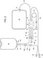
- Disposable set 40 is also illustrated in Fig. 1 , mated to cycler 20 to move fluid within the disposable set 40, e.g., to mix dialysis fluid as discussed herein.
- Disposable set 40 in the illustrated embodiment includes a disposable cassette 42, which may include a planar rigid plastic piece covered on one or both sides by a flexible sheet 48. Flexible sheet 48 pressed against housing 24 of cycler 20 forms a pumping and valving membrane.
- Fig. 2 illustrates that disposable cassette 42 includes fluid pump chambers 44 that operate with the pneumatic pump chambers located at housing 24 of cycler 20 and fluid valve chambers 46 that operate with the pneumatic valve chambers located at housing 24 of cycler 20.
- Figs. 1 and 2 further illustrate that disposable set 40 includes a heater/mixing line 60 that extends from a heater/mixing line port of cassette 42 and terminates at a heater/mixing bag 62.
- Disposable set 40 includes an upstream water line segment 64a that extends to a water inlet leg 92 of a Y-connector 90 (or T-connector, or the like) located just upstream of water accumulator 66.
- Y-connector 90 connects to water accumulator 66 via leg 94.
- a downstream water line segment 64b extends from a water outlet leg 96 of Y-connector 90 to cassette 42.
- upstream water line segment 64a begins at a water line connector 68 and is located upstream from water accumulator 66.
- Fig. 1 illustrates that water line connector 68 is removeably connected to a water outlet connector 228 of water purifier 210.
- Fig. 2 further illustrates that a last bag or sample line 72 may be provided that extends from a last bag or sample port of cassette 42.
- Last bag or sample line 72 terminates at a connector 74, which may be connected to a mating connector of a premixed last fill bag of dialysis fluid or to a sample bag or other sample collecting container.
- Last bag or sample line 72 and connector 74 may be used alternatively for a third type of concentrate if desired.
- the rigid portion of cassette 42 may be made for example of a thermal olefin polymer of amorphous structure ("TOPAS") cyclic olefin copolymer (“coc”).
- the flexible membranes of cassette 42 may be made for example of a copolyletser ether (“PCCE”) and may be of one or more layer.
- PCCE copolyletser ether
- Any of the tubing or lines and Y-connector 90 may be made for example of polyvinyl chloride (“PVC").
- any of the connectors may be made for example of acrylonitrile-butadiene-styrene ("ABS", e.g., for Y-connector 90 (alternatively), for connector 70 of heater/mixing bag or container 62 and/or for concentrate connectors 80a, 80b, 82a, 82b discussed below), acrylic (e.g., for drain line connector 58) or PVC (e.g., for water line connector water line connector 68).
- ABS acrylonitrile-butadiene-styrene
- acrylic e.g., for drain line connector 58
- PVC e.g., for water line connector water line connector 68
- Any of the bags or containers, such as heater/mixing bag or container 62 discussed below, may be made of PVC.
- the materials for any of the above components may be changed over time.
- Control unit 22 may be programmed to cause cycler 20 to perform one or more mixing action to help mix dialysis fluid properly and homogeneously for treatment.
- any of fluid pump chambers 44 may be caused to withdraw into the pump chambers some amount of mixed fluid (e.g., made from one or both first and second concentrates 84a, 84b and WFPD) from heater/mixing bag 62 and send such mixture back to heater/mixing bag 62 and repeat this procedure multiple times (described herein as a mixing sequence or "waffling").
- control unit 22 in an embodiment causes cycler 20 to close all fluid valve chambers 46 at cassette 42 except for the fluid valve chamber 46 to heater/mixing line 60 and heater/mixing bag 62.
- Fluid pump chambers 44 are stroked sequentially and repeatedly (i) pulling a possibly unmixed fluid combination of WFPD and concentrates from heater/mixing bag 62 into the pump chambers, followed by (ii) pushing the mixed WFPD and concentrates from the pump chambers back to heater/mixing bag 62 and (iii) repeating (i) and (ii) at least one time.
- Control unit 22 may be programmed to stroke fluid pump chambers 44 together so that they both pull and push at the same time, or alternatingly so that one pump chamber 44 pulls from heater/mixing bag 62, while the other pump chamber 44 pushes to heater/mixing bag 62, creating turbulence in heater/mixing line 60.
- heater/mixing container or bag 62 with cassette 42 via heater/mixing line 60 enables the WFPD from accumulator 66 and concentrates from first and second concentrate containers 84a and 84b to be at least partially mixed prior to entering container or bag 62. Even if cassette 42 is not provided, the WFPD and at least one concentrate will mix partially in heater/mixing line 60 prior to reaching the container or bag.
- Sterilizing grade filters 100a and 100b may, for example, be Pall IV-5 or GVS Speedflow filters, or be filters provided by the assignee of the present disclosure.
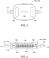
- Filters 100a and 100b include a housing 102, which may be made of any medical grade polymer, such as any of the materials listed above. Housing 102 includes or defines a filter inlet 104 and a filter outlet 106.
- Filter inlet 104 of upstream sterilizing grade filter 100a is connected sealingly, e.g., via a compression, hose barb, or luer connection, to the upstream-most section of upstream water line segment 64a, while filter outlet 106 of upstream sterilizing grade filter 100a is connected sealingly, e.g., via a compression, hose barb, or luer connection, to a section 64c ( Fig. 5 ) of upstream water line segment 64a located between filters 100a and 100b.
- Filter inlet 104 of downstream sterilizing grade filter 100b is connected sealingly, e.g., via a compression, hose barb, or luer connection, to section 64c ( Fig.
- upstream water line segment 64a while filter outlet 106 of downstream sterilizing grade filter 100b is connected sealingly, e.g., via a compression, hose barb, or luer connection, to a downstream-most section of upstream water line segment 64a.
- Fig. 4 illustrates how water flows through the illustrated embodiment for filters 100a and 100b.
- Water enters though inlet 104 and flows along an inlet path 112.
- Inlet path 112 splits into inlet branches 114a and 114b.
- Inlet branch 114a extends above a hydrophilic membrane 110a
- inlet branch 114b extends below a hydrophilic membrane 110b in the orientation of filter 100a, 100b in Fig. 4 .
- Hydrophilic materials are liquid passing and air retaining when wetted. Hydrophilic membranes 110a and 110b accordingly allow liquid to pass through, while not allowing air to pass through when wetted with liquid, thereby preventing air entering filters 100a and 100b from becoming entrained in the water traveling through the filters.
- Pore sizes for hydrophilic membranes 110a and 110b may again, for example, be less than a micron, such as 0.1 or 0.2 micron.
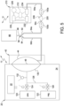
- a pressure sensor 132 is located along pneumatic line 128.
- the dashed lines extending from control unit 22, solenoid valves 124 and 126 and pressure sensor 132 indicate that solenoid valves 124 and 126 and pressure sensor 132 may receive power and/or signals from control unit 22 and may send electrical or signal readings to control unit 22.
- the dashed lines extending from control unit 222 and water pump 226 of water purifier 210 likewise indicate that control unit 222 may electrically control water pump 226 and receive electrical or signal feedback from water pump 226.
- control unit 22 causes a pressure decay test on the membranes 110a and 110b of downstream sterilizing grade filter 100b to be initiated.
- control unit 22 closes (or keeps closed) positive pneumatic valve 126 and opens negative pneumatic valve 124 to pull a vacuum on flexible sheet 48 and correspondingly on the air in downstream water line segment 64b, Y-connector 90, upstream water line segment 64a, and the inside of membrane housing 116 holding the wetted hydrophilic membranes 110a and 110b of downstream filter 100b.
- flexible sheet 48 is pulled only part of the way towards the wall of pneumatic pump chamber 130.
- water purifier 210 delivers a small volume of purified water through each filter 110a and 100b to wet out each hydrophilic membrane 110a and 110b as discussed above.
- a product water valve at purifier 210 is closed at water purifier 210 and cycler 20 begins to evacuate the water and air from water lines 64a and 64b until a vacuum pressure stabilizes at 25 kPa, which is enough to collapse water accumulator 66 (desirable for the pressure decay test) but not the tubing of water line segments 64a and 64b.
- Cycler 20 then stops pulling the vacuum and begins to monitor the negative pressure in water lines 64a and 64b, which may last for up to twenty seconds.
- cycler 20 assumes and error in hydrophilic membrane 110a or 110b of downstream filter 100b and reacts as described herein.
- control unit 22 determines that downstream sterilizing grade filter 100b is intact, then control unit 22 continues treatment.
- control unit 22 determines that downstream sterilizing grade filter 100b is compromised, then control unit 22 discontinues treatment, alarms audibly, visually or audiovisually, and alerts the patient or caregiver to remove current disposable set 40 and to install a new set to continue treatment.
- method 250 ends.
- downstream sterilizing grade filter 100b is determined to be compromised, it is highly likely that upstream sterilizing grade filter 100a is still intact. So if for example the failed integrity test is performed after treatment, the treatment has nevertheless been performed in all probability using properly sterilized dialysis fluid.
- Fig. 5 illustrates in phantom an alternative embodiment in which a connector 200 housing one or more hydrophobic filter or vent 208 is located between upstream and downstream sterilizing grade filters 100a and 100b at section 64c.
- filters 100a and 100b do not need hydrophobic vents 108a to 108d. If one or more wetted hydrophilic membrane 110a and 110b of downstream sterilizing grade filter 100b is not in tact, e.g., if a tear exists in one of the membranes, then air will enter into the otherwise closed membrane housing 116 via hydrophobic vent 208.
- control unit 22 of cycler 20 and/or control unit 212 of water purifier 210 alternatively or additionally performs a second integrity test using equipment 230, 232 and 234 of water purifier 210 to interrogate sterilizing grade filters 100a and 100b.
- control unit 22 of cycler 20 and/or control unit 212 of water purifier 210 is/are configured to examine the ratio of the pressure to flow rate (or flow rate to pressure) to inspect the integrity of the hydrophilic membranes 110a and 110b of both sterilizing grade filters 100a and 100b.
- control unit 212 of the water purifier 210 has the capability to monitor the ratio over an extended period and to detect changes in performance of hydrophilic membranes 110a and 110b of sterilizing grade filters 100a and 100b, compensating with greater or lower pressure and alerting the user as needed.
- Control unit 212 of water purifier 210 may (i) report results to control unit 22 of the cycler 20, which notifies the patient of any problem via user interface 30 or (ii) report results at user interface 220 of water purifier 210 for notification.
- water purifier 210 maintains a purified water flow rate through the sterilizing grade filters 100a and 100b using an electronic flow meter 230 outputting to control unit 212. In doing so, water purifier 210 compensates (raises or lowers) the pressure at which purified water is delivered to maintain the constant flow rate set in control unit 212 using an electronic pressure regulator 232 under command of control unit 212 and an electronic pressure gauge outputting to control unit 212. Should one or both filters 100a and 100b be compromised or should a leak occur in the purified water line segments 64a and 64b, the preset flow rate measured at flow meter 230 will be achieved at a lower pressure, which the water purifier 210 controls via regulator 232 and measures via gauge 234.
- the disposable set is described herein as having a water accumulator, and wherein the water purifier pumps water to the filters and the water purifier, in alternative embodiments (i) the medical fluid delivery machine or cycler may instead pump water into the water accumulator and/or the filters to wet the filters or (ii) the water accumulator is not provided and either one or both of the water purifier and/or the medical fluid delivery machine or cycler pumps water to wet at least one membrane of at least one sterilizing grade filter.
Landscapes
- Health & Medical Sciences (AREA)
- Heart & Thoracic Surgery (AREA)
- Urology & Nephrology (AREA)
- Emergency Medicine (AREA)
- Anesthesiology (AREA)
- Engineering & Computer Science (AREA)
- Vascular Medicine (AREA)
- Biomedical Technology (AREA)
- Hematology (AREA)
- Life Sciences & Earth Sciences (AREA)
- Animal Behavior & Ethology (AREA)
- General Health & Medical Sciences (AREA)
- Public Health (AREA)
- Veterinary Medicine (AREA)
- External Artificial Organs (AREA)
Applications Claiming Priority (3)
| Application Number | Priority Date | Filing Date | Title |
|---|---|---|---|
| US201862672316P | 2018-05-16 | 2018-05-16 | |
| EP19756439.6A EP3793636B1 (de) | 2018-05-16 | 2019-05-16 | Dialysetransferset mit filterintegritätsprüfung |
| PCT/US2019/032626 WO2019222473A1 (en) | 2018-05-16 | 2019-05-16 | Dialysis transfer set having filter integrity testing |
Related Parent Applications (2)
| Application Number | Title | Priority Date | Filing Date |
|---|---|---|---|
| EP19756439.6A Division EP3793636B1 (de) | 2018-05-16 | 2019-05-16 | Dialysetransferset mit filterintegritätsprüfung |
| EP19756439.6A Division-Into EP3793636B1 (de) | 2018-05-16 | 2019-05-16 | Dialysetransferset mit filterintegritätsprüfung |
Publications (2)
| Publication Number | Publication Date |
|---|---|
| EP4527424A2 true EP4527424A2 (de) | 2025-03-26 |
| EP4527424A3 EP4527424A3 (de) | 2025-06-18 |
Family
ID=67704548
Family Applications (2)
| Application Number | Title | Priority Date | Filing Date |
|---|---|---|---|
| EP25156935.6A Pending EP4527424A3 (de) | 2018-05-16 | 2019-05-16 | Dialysetransferset mit filterintegritätsprüfung |
| EP19756439.6A Active EP3793636B1 (de) | 2018-05-16 | 2019-05-16 | Dialysetransferset mit filterintegritätsprüfung |
Family Applications After (1)
| Application Number | Title | Priority Date | Filing Date |
|---|---|---|---|
| EP19756439.6A Active EP3793636B1 (de) | 2018-05-16 | 2019-05-16 | Dialysetransferset mit filterintegritätsprüfung |
Country Status (5)
| Country | Link |
|---|---|
| US (2) | US12161786B2 (de) |
| EP (2) | EP4527424A3 (de) |
| CN (1) | CN112105400B (de) |
| ES (1) | ES3017702T3 (de) |
| WO (1) | WO2019222473A1 (de) |
Families Citing this family (4)
| Publication number | Priority date | Publication date | Assignee | Title |
|---|---|---|---|---|
| WO2022051456A1 (en) * | 2020-09-04 | 2022-03-10 | Byonyks Medical Devices, Inc. | Transfer sets with filters, including transfer sets for peritoneal dialysis systems, and associated systems, devices, and methods |
| WO2022236053A1 (en) * | 2021-05-06 | 2022-11-10 | Baxter International Inc. | Automated peritoneal dialysis system including enhanced pressure sensing features |
| IT202200013750A1 (it) * | 2022-06-29 | 2023-12-29 | Baxter Int | Dialysis system having filter testing |
| US20250213762A1 (en) * | 2023-12-28 | 2025-07-03 | Baxter International Inc. | Apparatus and methods for a dialysis system having an ultrafilter |
Family Cites Families (10)
| Publication number | Priority date | Publication date | Assignee | Title |
|---|---|---|---|---|
| DE19700466A1 (de) * | 1997-01-09 | 1998-07-16 | Polaschegg Hans Dietrich Dr | Einrichtung und Verfahren zur Hämodiafiltration |
| US6758975B2 (en) * | 2001-02-16 | 2004-07-06 | Piedmont Renal Clinic, Pa | Automated peritoneal dialysis system and process with in-line sterilization of dialysate |
| CN101232910B (zh) * | 2005-07-01 | 2011-12-14 | 甘布罗伦迪亚股份公司 | 一种测试过滤器的装置 |
| KR101861192B1 (ko) * | 2007-02-27 | 2018-05-28 | 데카 프로덕츠 리미티드 파트너쉽 | 혈액투석 장치 및 방법 |
| MX2011002251A (es) * | 2008-08-27 | 2011-05-19 | Deka Products Lp | Arquitectura de control y metodos para sistemas de tratamiento de la sangre. |
| US20130270165A1 (en) * | 2010-08-25 | 2013-10-17 | Jerry Shevitz | Fluid Filtration Systems |
| JP5724485B2 (ja) * | 2011-03-15 | 2015-05-27 | 澁谷工業株式会社 | 血液透析装置 |
| JP6049685B2 (ja) * | 2011-03-23 | 2016-12-21 | ネクステージ メディカル インコーポレイテッド | 腹膜透析使い捨てユニット、コントローラ、腹膜透析システム |
| EP3197518B1 (de) * | 2014-09-25 | 2019-07-24 | NxStage Medical, Inc. | Arzneimittelzubereitung sowie behandlungsvorrichtungen und -systeme |
| CA3280035A1 (en) * | 2016-05-06 | 2025-10-30 | Gambro Lundia Ab | Systems and methods for peritoneal dialysis having point of use dialysis fluid preparation including mixing and heating therefor |
-
2019
- 2019-05-16 EP EP25156935.6A patent/EP4527424A3/de active Pending
- 2019-05-16 ES ES19756439T patent/ES3017702T3/es active Active
- 2019-05-16 WO PCT/US2019/032626 patent/WO2019222473A1/en not_active Ceased
- 2019-05-16 CN CN201980031747.4A patent/CN112105400B/zh active Active
- 2019-05-16 US US17/055,864 patent/US12161786B2/en active Active
- 2019-05-16 EP EP19756439.6A patent/EP3793636B1/de active Active
-
2024
- 2024-12-09 US US18/974,125 patent/US20250099659A1/en active Pending
Also Published As
| Publication number | Publication date |
|---|---|
| CN112105400B (zh) | 2024-04-16 |
| US20210220539A1 (en) | 2021-07-22 |
| ES3017702T3 (en) | 2025-05-13 |
| EP3793636B1 (de) | 2025-03-19 |
| WO2019222473A1 (en) | 2019-11-21 |
| US20250099659A1 (en) | 2025-03-27 |
| US12161786B2 (en) | 2024-12-10 |
| EP4527424A3 (de) | 2025-06-18 |
| CN112105400A (zh) | 2020-12-18 |
| EP3793636A1 (de) | 2021-03-24 |
Similar Documents
| Publication | Publication Date | Title |
|---|---|---|
| US11672895B2 (en) | Method for peritoneal dialysis and extracorporeal blood treatments | |
| US20250099659A1 (en) | Dialysis transfer set having filter integrity testing | |
| US11110213B2 (en) | Mixing for online medical fluid generation | |
| US12433979B2 (en) | Peritoneal dialysis patient line with sterilizing filter and drain bypass | |
| EP3703777A1 (de) | Dextrosekonzentrat für das dialysat und zur desinfektion | |
| MXPA06006835A (es) | Sistemas y metodos de control de flujo para terapia medica de fluidos. | |
| US20250009950A1 (en) | Peritoneal dialysis system including a patient line filter having a tubular membrane | |
| EP4547295B1 (de) | Dialysesystem mit filterprüfung |
Legal Events
| Date | Code | Title | Description |
|---|---|---|---|
| PUAI | Public reference made under article 153(3) epc to a published international application that has entered the european phase |
Free format text: ORIGINAL CODE: 0009012 |
|
| STAA | Information on the status of an ep patent application or granted ep patent |
Free format text: STATUS: REQUEST FOR EXAMINATION WAS MADE |
|
| 17P | Request for examination filed |
Effective date: 20250210 |
|
| AC | Divisional application: reference to earlier application |
Ref document number: 3793636 Country of ref document: EP Kind code of ref document: P |
|
| AK | Designated contracting states |
Kind code of ref document: A2 Designated state(s): AL AT BE BG CH CY CZ DE DK EE ES FI FR GB GR HR HU IE IS IT LI LT LU LV MC MK MT NL NO PL PT RO RS SE SI SK SM TR |
|
| PUAL | Search report despatched |
Free format text: ORIGINAL CODE: 0009013 |
|
| AK | Designated contracting states |
Kind code of ref document: A3 Designated state(s): AL AT BE BG CH CY CZ DE DK EE ES FI FR GB GR HR HU IE IS IT LI LT LU LV MC MK MT NL NO PL PT RO RS SE SI SK SM TR |
|
| RIC1 | Information provided on ipc code assigned before grant |
Ipc: A61M 1/28 20060101ALI20250515BHEP Ipc: A61M 1/14 20060101ALI20250515BHEP Ipc: A61M 1/16 20060101AFI20250515BHEP |