EP4524518A2 - Verbesserte magnetische einsetzmesser und verfahren - Google Patents
Verbesserte magnetische einsetzmesser und verfahren Download PDFInfo
- Publication number
- EP4524518A2 EP4524518A2 EP25154274.2A EP25154274A EP4524518A2 EP 4524518 A2 EP4524518 A2 EP 4524518A2 EP 25154274 A EP25154274 A EP 25154274A EP 4524518 A2 EP4524518 A2 EP 4524518A2
- Authority
- EP
- European Patent Office
- Prior art keywords
- meter
- front surface
- sensor head
- head tube
- electrodes
- Prior art date
- Legal status (The legal status is an assumption and is not a legal conclusion. Google has not performed a legal analysis and makes no representation as to the accuracy of the status listed.)
- Pending
Links
Images





Classifications
-
- G—PHYSICS
- G01—MEASURING; TESTING
- G01F—MEASURING VOLUME, VOLUME FLOW, MASS FLOW OR LIQUID LEVEL; METERING BY VOLUME
- G01F1/00—Measuring the volume flow or mass flow of fluid or fluent solid material wherein the fluid passes through a meter in a continuous flow
- G01F1/56—Measuring the volume flow or mass flow of fluid or fluent solid material wherein the fluid passes through a meter in a continuous flow by using electric or magnetic effects
- G01F1/58—Measuring the volume flow or mass flow of fluid or fluent solid material wherein the fluid passes through a meter in a continuous flow by using electric or magnetic effects by electromagnetic flowmeters
- G01F1/584—Measuring the volume flow or mass flow of fluid or fluent solid material wherein the fluid passes through a meter in a continuous flow by using electric or magnetic effects by electromagnetic flowmeters constructions of electrodes, accessories therefor
-
- G—PHYSICS
- G01—MEASURING; TESTING
- G01F—MEASURING VOLUME, VOLUME FLOW, MASS FLOW OR LIQUID LEVEL; METERING BY VOLUME
- G01F1/00—Measuring the volume flow or mass flow of fluid or fluent solid material wherein the fluid passes through a meter in a continuous flow
- G01F1/56—Measuring the volume flow or mass flow of fluid or fluent solid material wherein the fluid passes through a meter in a continuous flow by using electric or magnetic effects
- G01F1/58—Measuring the volume flow or mass flow of fluid or fluent solid material wherein the fluid passes through a meter in a continuous flow by using electric or magnetic effects by electromagnetic flowmeters
- G01F1/586—Measuring the volume flow or mass flow of fluid or fluent solid material wherein the fluid passes through a meter in a continuous flow by using electric or magnetic effects by electromagnetic flowmeters constructions of coils, magnetic circuits, accessories therefor
-
- F—MECHANICAL ENGINEERING; LIGHTING; HEATING; WEAPONS; BLASTING
- F15—FLUID-PRESSURE ACTUATORS; HYDRAULICS OR PNEUMATICS IN GENERAL
- F15D—FLUID DYNAMICS, i.e. METHODS OR MEANS FOR INFLUENCING THE FLOW OF GASES OR LIQUIDS
- F15D1/00—Influencing flow of fluids
- F15D1/002—Influencing flow of fluids by influencing the boundary layer
- F15D1/0025—Influencing flow of fluids by influencing the boundary layer using passive means, i.e. without external energy supply
- F15D1/003—Influencing flow of fluids by influencing the boundary layer using passive means, i.e. without external energy supply comprising surface features, e.g. indentations or protrusions
-
- F—MECHANICAL ENGINEERING; LIGHTING; HEATING; WEAPONS; BLASTING
- F15—FLUID-PRESSURE ACTUATORS; HYDRAULICS OR PNEUMATICS IN GENERAL
- F15D—FLUID DYNAMICS, i.e. METHODS OR MEANS FOR INFLUENCING THE FLOW OF GASES OR LIQUIDS
- F15D1/00—Influencing flow of fluids
- F15D1/002—Influencing flow of fluids by influencing the boundary layer
- F15D1/0025—Influencing flow of fluids by influencing the boundary layer using passive means, i.e. without external energy supply
- F15D1/003—Influencing flow of fluids by influencing the boundary layer using passive means, i.e. without external energy supply comprising surface features, e.g. indentations or protrusions
- F15D1/005—Influencing flow of fluids by influencing the boundary layer using passive means, i.e. without external energy supply comprising surface features, e.g. indentations or protrusions in the form of dimples
-
- F—MECHANICAL ENGINEERING; LIGHTING; HEATING; WEAPONS; BLASTING
- F15—FLUID-PRESSURE ACTUATORS; HYDRAULICS OR PNEUMATICS IN GENERAL
- F15D—FLUID DYNAMICS, i.e. METHODS OR MEANS FOR INFLUENCING THE FLOW OF GASES OR LIQUIDS
- F15D1/00—Influencing flow of fluids
- F15D1/10—Influencing flow of fluids around bodies of solid material
- F15D1/12—Influencing flow of fluids around bodies of solid material by influencing the boundary layer
-
- G—PHYSICS
- G01—MEASURING; TESTING
- G01F—MEASURING VOLUME, VOLUME FLOW, MASS FLOW OR LIQUID LEVEL; METERING BY VOLUME
- G01F1/00—Measuring the volume flow or mass flow of fluid or fluent solid material wherein the fluid passes through a meter in a continuous flow
- G01F1/56—Measuring the volume flow or mass flow of fluid or fluent solid material wherein the fluid passes through a meter in a continuous flow by using electric or magnetic effects
- G01F1/58—Measuring the volume flow or mass flow of fluid or fluent solid material wherein the fluid passes through a meter in a continuous flow by using electric or magnetic effects by electromagnetic flowmeters
- G01F1/588—Measuring the volume flow or mass flow of fluid or fluent solid material wherein the fluid passes through a meter in a continuous flow by using electric or magnetic effects by electromagnetic flowmeters combined constructions of electrodes, coils or magnetic circuits, accessories therefor
Definitions
- This application relates to flow meters and more particularly to magnetic insertion meters.
- Repeatability is the ability of a meter to obtain the same results under the same conditions.
- Linearity is the degree to which a meter's output is linear to the amount of flow being transferred through a pipe or other conduit.
- Insertion flow meters are typically less accurate than in-line meters because they have worse repeatability and linearity than an in-line meter. This is in part because insertion meters by the nature of their design can only measure a point on the velocity profile, or at lease only a small portion thereof, and this measurement must be correlated to estimate the average velocity of flow through the pipe. The shape of the velocity profile changes with flow, pressure, and temperature, among other factors, which affects the translation of this point measurement to total average velocity.
- Inline meters measure across the entire velocity profile enabling an accurate direct measurement of the average velocity of flow through the pipe. Consequently, insertion magnetic meters may typically have an accuracy of +/-2% of reading, whereas in-line meters have accuracies as low as +/- 0.2% of reading.
- insertion meters are advantageous as compared to in-line meters because insertion meters are modular and do not require complete system shutdown for installation and repair. In addition, insertion meters cost less and have a lower installation cost. To install an inline meter, the system has to be shut down, a section of pipe cut out, flanges welded in place and then the meter is mounted between the two flanges. Insertion meters can be mounted though a common ball valve.
- a magnetic insertion meter having a sensor head cylinder having a textured front surface and at least two electrodes.
- an insertion meter includes a field coil configured to emit an alternating magnetic field when energized with an alternating current.
- a textured front surface is an upstream surface.
- a textured front surface is at least one of an abrasive on a substrate, an impregnated abrasive, a deposited abrasive, and/or an abrasive layer.
- a textured front surface is sandpaper.
- a textured front surface has a higher roughness than a material forming the sensor head tube.
- a textured front surface includes at least one groove. In another aspect of the disclosure, a textured front surface includes two grooves extending along the longitudinal axis of the sensor head cylinder. In one aspect of the disclosure, a textured front surface includes dimples. In another aspect of the disclosure, a plurality of dimples is equally spaced apart from each other. In another aspect of the disclosure, a plurality of dimples forms a pattern in which three of the plurality of dimples form an equilateral triangle. In one aspect of the disclosure, a textured front surface includes a plurality of columns of dimples. In one aspect of the disclosure, a textured front surface includes from about 3 to about 7 columns of dimples.
- a textured front surface includes dimples.
- a textured front surface is adapted to alter the boundary layer of a fluid flowing over the sensor head tube as compared to the same sensor head tube without the textured front surface.
- a textured front surface is adapted to move the separation point of a fluid flowing over the sensor head tube towards the front surface as compared to the same sensor head tube without the textured front surface.
- a textured surface is a surface contour.
- a method of measuring flow includes providing a magnetic insertion meter that includes a sensor head cylinder having a textured front surface and at least two electrodes and measuring the output of said electrodes.
- a textured front surface is at least one of an abrasive on a substrate, an impregnated abrasive, a deposited abrasive, and/or an abrasive layer.
- a textured front surface includes at least one of dimples and/or grooves.
- FIG. 1 shows a cross section of an insertion meter 100, having the shape of a cylinder, looking down the longitudinal access of an example insertion meter 100.
- the insertion meter 100 may be, for example, part of the example sensor assemblies described in US application 16/233,915, filed on December 27, 2018 , titled “Scalable Monolithic Sensor Assembly, Controller, and Methods of Making and Installing Same," and published as US 2019/0204129 , the entirety of which is included herein as Appendix A.
- the cross section is taken at electrodes 110.
- the insertion meter 100 includes a cylindrical sensor head tube 140, that is inserted into the pipe carrying a suitably conductive fluid 180.
- the insertion meter 100 generates a magnetic field using field coils energized by an alternating current.
- the conductor i.e., the conductive fluid
- the insertion meter 100 measures the electrical potential (voltage or "V") generated by the flow velocity between at least two electrodes. Such a potential difference may be measured, for example, between at least one top electrode and at least one bottom electrode.
- the insertion meter 100 may have 2 or more electrodes disbursed from top to bottom of its longitudinal axis.
- the insertion meter 100 may include 1 or more top electrodes, one or more bottom electrodes, and one or more center electrodes.
- the center electrodes act as an electrical reference, whereas the voltage potential is sampled between pairs of top and bottom electrodes.
- the two electrodes 110 shown in FIG. 1 share the same longitudinal height.
- the electrodes 110 may each be top electrodes, bottom electrodes, or references electrodes.
- the electrodes 110 shown in FIGS. 1 may be electrically connected to form a single electrode or they be electrically isolated from each other to form two independent electrodes. In an example independent configuration in which the electrodes 110 are bottom electrodes, a first potential could be measured between one of the electrodes 110 and a respective top electrode and a second potential could be measured between the other electrode 110 and a different top electrode.
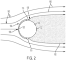
- FIG. 2 shows insertion meters 100 in a flowing fluid 180 at an example velocity in the direction of the arrows 182.
- the flowing fluid 180 at arrows 182 represent a bulk fluid that is turbulent, as shown, the flowing fluid reaches a stagnation point 186, at which the fluid flow is a minimum, when the fluid contacts the front surface 120.
- the fluid 180 also forms a laminar boundary layer 184 (or boundary layer 184), which is a transition between the stagnation point and the bulk terminal flow 182, as it contacts the front surface 120 facing the oncoming fluid flow.
- the front surface 120 i.e., the surface facing the oncoming fluid flow, will also be referred to herein as the upstream surface.
- the boundary layer 184 becomes unstable or otherwise transitions away from the surface of the insertion meter 100 as it flows towards the back 122, or downstream surface, of the insertion meter 100. This boundary layer transition is indicated as separation point 105.
- the location of the separation point 105 is not consistent because fluid flow is chaotic and it is affected by changes in the amount of fluid flow across the insertion meter 100, as well as fluid characteristics, for example, velocity of the fluid, temperature, viscosity, density, and surface finish of the cylinder.
- the location of the separation point 105 can also change based on whether the flow rate is increasing or decreasing to a given velocity.
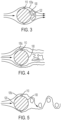
- FIGS. 3 through 5 show three different velocities of the same fluid in increasing order, i.e., the FIG. 5 fluid velocity is higher than the fluid velocity of FIG4 , which is higher than the fluid velocity of FIG.3 .
- separation point 105a is typically between the electrodes 110 and back 122.
- FIG. 3 separation point 105a is typically between the electrodes 110 and back 122.
- the velocity of the fluid is greater than that of FIG. 3 and less than that of FIG. 5 and the separation point 105b has shifted to near electrode 110.
- the velocity of the fluid is more than that of FIGS. 3 and FIG. 4 and separation point 105c has shifted closer to the front 120 of insertion meter 100, i.e., closer to the direction from which the fluid is flowing.
- the inconsistencies in the boundary layer / separation point 105 (105a, 105b, 105c) location contribute to the decrease in linearity and repeatability experienced with prior insertion meters. That is, an unstable boundary layer at the sensor electrodes 110 can prevent accurate and repeatable results as compared to a more stable boundary layer.
- the separation point 105a is closer to electrode 110 (whether downstream or upstream) which, in the right conditions, can cause more variance in the measurements taken at electrode 105a. While the separation point 105c of FIG. 5 has be shifted towards front surface 120, the variation in the boundary layer shown between FIG. 3 through FIG. 5 can cause an insertion meter 100 to deviate from calibration.
- FIG. 6 shows example meter outputs (1P-RUN1 through 1P-RUN5) of an example insertion meter 100 ( FIG. 1 ) as a graph of meter factor expressed as (LPIP Pulse / Isoil Gal) against nominal flow rate expressed in feet per second (ft/s).
- the meter factor (or correction factor) is normally dimensionless and is calculated as the ratio of the meter output to value determined by a standard reference meter, for example Insertion Meter Pulse/Reference (Ref) Meter Pulse This can be computed from rate measurements or quantity measurements.
- the different line traces show repeated test runs of the same insertion meter 100 under the same conditions. It is shown that both repeatability and linearity can be improved.
- Linearity also simplifies corrections to other operating conditions, improves reproducibility between meters (unit to unit variation), shortens the manufacturing validation cycle to confirm accuracy of the meter, and limits the need to test multiple meters units to determine characteristic curve, that is, fewer units are required to characterize multiple pipes/sizes. If the meter factor is constant, it is assumed, while the value may change, it will be constant for other fluids or flow conditions. It is much easier to determine corrections for other flow conditions and fluids if the relationship is linear.
- FIG. 7 shows an insertion meter 200 having electrodes 210.
- Insertion meter 200 and electrodes 210 are the same as insertion meter 100 and electrodes 110, respectively, except that insertion meter 200 includes textured surface 230 on the front 220 of insertion meter 200. While the specific configuration of textured surface 230 may vary based on the particular operating conditions of the insertion meter (e.g., meter circumference, pipe diameter, pipe flow rate, fluid type, fluid velocity, fluid density, etc.), the textured surface 230 should be textured sufficiently to trip or manipulate, the boundary layer such that the separation point (see, e.g., 105 , FIG.
- textured surface 230 should be rougher than the remainder of sensor head tube 240 of insertion meter 200.
- textured surface 230 is rougher than the material forming the sensor head tube (e.g., smooth plastic and metal).
- textured surface 230 may be, for example, a sandpaper or other similar abrasive on a substrate adhered to the sensor head tube 240.
- Example abrasives on substrates include, for example, sand, glass, aluminum oxide, silicon carbide, emery cloth, pumice, crocus cloth, or the like. While this application discusses the use of paper as a substrate, other flexible substrates, for example, cloth, adhesive, or polymer, may also be used as well as inflexible substrates that are formed or machined to the curvature of the outside circumference of the sensor head tube 240.
- the abrasives may further be impregnated or deposited into or onto the surface without a substrate as an abrasive layer.
- the textured surface 230 may, in one example, extend the length of the sensor head tube 240 or be applied locally in the regions near electrodes 210. The amount of texture will depend on the type of material used, the size and shape of the insertion meter and flow pipe, and the characteristics of the fluid, but should nevertheless be sufficiently textured to manipulate the boundary layer as discussed above.
- a sandpaper textured surface 230 may include a 40-80 grit adhesive tape having a substrate thickness of about 0.030 inches and having a width of about 0.360 inches to about 0.400 inches, inclusive, the width being the dimension which would wrap around the circumference of the sensor head tube 240.
- the sandpaper textured surface may, in one example, be applied centered on the point of stagnation and along the full length of the meter, or effectively the full length of the sensing portion of the meter sensor head tube 240.
- FIG. 8 shows example meter outputs (SAND1-RUN1-90deg through SAND1-RUN3-90deg) of an example insertion meter 200 ( FIG. 7 ) as a graph of Meter Factor expressed as (Meter pulse/Ref Meter Pulse) against nominal flow rate expressed in feet per second (ft/s).
- the different line traces show repeated test runs of the same insertion meter 200 in the same conditions. It is shown that both repeatability and linearity are improved over that of insertion meter 100 ( FIG. 1 ). The improved linearity simplifies calibration and improves performance in different pipes and fluids.
- FIG. 9 shows an example embodiment of an insertion meter 300 having electrodes 310. Insertion meter 300 and electrodes 310 are the same as insertion meter 200 and electrodes 210, respectively, except that textured surface of insertion meter 300 includes two longitudinal notches 330 or grooves within the sensor head tube 340 on the front 320 of insertion meter 300. The notches 330 run along the longitudinal axis of the insertion meters 300 between the electrodes 310. The notches 330 also serve to manipulate the boundary layer as discussed above with respect to insertion meter 200.
- the textured surface includes columns of dimples, for example, those dimples found in typical golf balls.
- the textured surface may include a plurality of columns of dimples.
- the textured surface includes about 3 to about 7 columns of dimples.
- the textured surface includes more than 7 columns of dimples.
- the specific textured surface features discussed above may also be combined.
- the textured surface may include longitudinal grooves as well as columns of dimples.
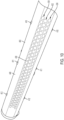
- FIGS 10 shows an insertion meter 400 of similar configuration as insertion meters 300, 200, and 100, including for example a plurality of electrodes including two top electrodes 410, two center or reference electrodes 411, and two bottom electrodes 412.
- the textured surface of insertion meter 400 includes dimples 430 formed on or within the sensor head tube 440.
- the dimples 430 of insertion meter 400 include 3 columns of dimples, with the center column 432 being offset longitudinally from the outer two columns 434 of dimples 430, which results in a pattern of one by two count rows. i.e. alternating between 1 dimple and 2 dimple rows.
- adjacent dimples 430 form an equilateral triangle such that gap between any two dimples 430 remain consistent.
- the dimples 430 extend the longitudinal length of the sensor head tube beyond the top electrodes 410 and bottom electrodes 412 in both directions.
- the dimples 430 may be formed as an additional surface that is added to the sensor head tube 440 or may be formed within the sensor head tube 440 by, for example, milling or during the formation of the sensor head tube 440 itself. While the size and configuration of each of the dimples can be manipulated to depending on the particular sensor installation, as shown in FIG. 10 as one example, each of the dimples 140 have about a 0.125 inch radius cut with a 1 ⁇ 4" ball end mill that is .020" deep into sensor head tube 440. And adjacent dimple has about a 0.20 inch gap between them.
- the arc length between each hole in a specific row is about 35 to about 36 degrees, inclusive, or specifically as shown about 35.35 degrees.
- the dimples 430 are only shown in FIG. 10 partially surrounding the sensor head tube 440, in an alternative example, the dimples 430 may more fully surround, or even completely surround, the sensor head tube 440.
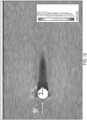
- FIGS. 11 and 12 are flow velocity stream models comparing insertion sensor 100 ( FIG.1 ) with insertion sensor 400 ( FIG. 10 ) in the same flow conditions.
- the scales have been normalized to 130in/sec.
- separation point 110 is closer to the electrode 105 than separation point 405 with respect to electrode 410.
- FIG. 13 shows an increase in linearity in the insertion meters with 7 rows of dimples (shown as unfilled purple dots) as compared to the smooth prior meters (shown in filled blue dots).
- the graph shows the ability to extend the linearity within +/- 1.5% of reading down to 1 ft/sec of nominal flow rate with an example insertion meter with seven columns of dimples 430.
- the cross-sectional shape of the insertion meter is altered to affect the boundary layer / electrode interaction.
- the insertion meter cross section can be formed in the shape of an oval or a tear drop to improve linearity and repeatability.
- the textured surface is itself a surface contour.
- a method of measuring flow within a pipe or conduit is also disclosed herein.
- the methods include providing a magnetic insertion meter that includes a sensor head cylinder having a textured front surface and at least two electrodes.
- Such insertion meters can be for example, those discussed above with reference to FIGS. 7-9 and their alternative embodiments.
- the method includes measuring the output of said electrodes.
Landscapes
- Physics & Mathematics (AREA)
- Electromagnetism (AREA)
- Fluid Mechanics (AREA)
- General Physics & Mathematics (AREA)
- Engineering & Computer Science (AREA)
- Power Engineering (AREA)
- Measuring Volume Flow (AREA)
Applications Claiming Priority (3)
| Application Number | Priority Date | Filing Date | Title |
|---|---|---|---|
| US201962809252P | 2019-02-22 | 2019-02-22 | |
| PCT/US2020/019294 WO2020172574A1 (en) | 2019-02-22 | 2020-02-21 | Improved insertion magnetic meters and methods |
| EP20759750.1A EP3927980B1 (de) | 2019-02-22 | 2020-02-21 | Verbesserte magnetische einsteckdurchflussmesser und verfahren |
Related Parent Applications (1)
| Application Number | Title | Priority Date | Filing Date |
|---|---|---|---|
| EP20759750.1A Division EP3927980B1 (de) | 2019-02-22 | 2020-02-21 | Verbesserte magnetische einsteckdurchflussmesser und verfahren |
Publications (2)
| Publication Number | Publication Date |
|---|---|
| EP4524518A2 true EP4524518A2 (de) | 2025-03-19 |
| EP4524518A3 EP4524518A3 (de) | 2025-05-21 |
Family
ID=72142401
Family Applications (2)
| Application Number | Title | Priority Date | Filing Date |
|---|---|---|---|
| EP20759750.1A Active EP3927980B1 (de) | 2019-02-22 | 2020-02-21 | Verbesserte magnetische einsteckdurchflussmesser und verfahren |
| EP25154274.2A Pending EP4524518A3 (de) | 2019-02-22 | 2020-02-21 | Verbesserte magnetische einsetzmesser und verfahren |
Family Applications Before (1)
| Application Number | Title | Priority Date | Filing Date |
|---|---|---|---|
| EP20759750.1A Active EP3927980B1 (de) | 2019-02-22 | 2020-02-21 | Verbesserte magnetische einsteckdurchflussmesser und verfahren |
Country Status (5)
| Country | Link |
|---|---|
| US (3) | US11378429B2 (de) |
| EP (2) | EP3927980B1 (de) |
| CN (1) | CN113474564B (de) |
| MX (1) | MX2021008511A (de) |
| WO (1) | WO2020172574A1 (de) |
Families Citing this family (1)
| Publication number | Priority date | Publication date | Assignee | Title |
|---|---|---|---|---|
| JP7202342B2 (ja) * | 2020-11-17 | 2023-01-11 | 株式会社Subaru | シボ加工面により空力特性を改善する車両、およびフロントバンパ部材 |
Citations (1)
| Publication number | Priority date | Publication date | Assignee | Title |
|---|---|---|---|---|
| US20190204129A1 (en) | 2017-12-28 | 2019-07-04 | Onicon Incorporated | Scalable monolithic sensor assembly, controller, and methods of making and installing same |
Family Cites Families (21)
| Publication number | Priority date | Publication date | Assignee | Title |
|---|---|---|---|---|
| US4089218A (en) * | 1976-12-29 | 1978-05-16 | Cushing Vincent J | Electromagnetic water current meter with staggered stick out electrodes |
| JPS5833539Y2 (ja) * | 1977-10-26 | 1983-07-27 | 株式会社東芝 | 插入形電磁流量計 |
| JPS55157728U (de) * | 1979-05-01 | 1980-11-13 | ||
| US4389898A (en) * | 1980-12-04 | 1983-06-28 | Long James C | Electromagnetic velocity transducer |
| US4459858A (en) * | 1981-09-18 | 1984-07-17 | Marsh-Mcbirney, Inc. | Flow meter having an electromagnetic sensor probe |
| DE3319807A1 (de) * | 1983-06-01 | 1984-12-06 | Turbo-Werk Messtechnik GmbH, 5000 Köln | Induktiver stroemungsmesser |
| JPH02103418A (ja) * | 1988-10-12 | 1990-04-16 | Toshiba Corp | 挿入式電磁流量計 |
| US5036711A (en) * | 1989-09-05 | 1991-08-06 | Fred P. Good | Averaging pitot tube |
| CN2115521U (zh) * | 1992-01-24 | 1992-09-09 | 天津市自动化仪表三厂 | 插入式电磁流量传感器 |
| US6431011B1 (en) * | 2000-11-02 | 2002-08-13 | Murray F. Feller | Magnetic flow sensor and method |
| BR0204017A (pt) * | 2001-02-06 | 2003-02-04 | Abb Metering Ltd | FluxÈmetro |
| ATE413535T1 (de) * | 2003-03-19 | 2008-11-15 | Vida Nikolaus Dr | Dreidimensionale oberflächenstruktur für reduzierten strömungswiderstand und verbesserten wärmeübergang |
| US7047822B2 (en) * | 2004-09-13 | 2006-05-23 | Veris, Inc. | Devices, installations and methods for improved fluid flow measurement in a conduit |
| GB0426007D0 (en) * | 2004-11-26 | 2004-12-29 | Univ Gent | Method and device for measuring pressure |
| JP4592405B2 (ja) * | 2004-12-06 | 2010-12-01 | 愛知時計電機株式会社 | 電磁流速センサ |
| US8684040B2 (en) * | 2007-05-25 | 2014-04-01 | The Regents Of The University Of Michigan | Reduction of vortex induced forces and motion through surface roughness control |
| US7437945B1 (en) * | 2008-02-14 | 2008-10-21 | Murray F Feller | Magnetic flow probe |
| CN203132612U (zh) * | 2013-03-07 | 2013-08-14 | 江苏华海测控技术有限公司 | 插入型磁电式流量计 |
| JP2015203608A (ja) * | 2014-04-11 | 2015-11-16 | 株式会社東芝 | 電磁流量計 |
| RU2018106882A (ru) * | 2015-07-28 | 2019-08-28 | Сентек Лтд | Электромагнитный датчик расхода |
| CN207147566U (zh) * | 2017-07-12 | 2018-03-27 | 襄阳西顿自动化仪表有限公司 | 一种传感器插入式电磁流量计 |
-
2020
- 2020-02-21 EP EP20759750.1A patent/EP3927980B1/de active Active
- 2020-02-21 US US16/797,814 patent/US11378429B2/en active Active
- 2020-02-21 MX MX2021008511A patent/MX2021008511A/es unknown
- 2020-02-21 WO PCT/US2020/019294 patent/WO2020172574A1/en not_active Ceased
- 2020-02-21 EP EP25154274.2A patent/EP4524518A3/de active Pending
- 2020-02-21 CN CN202080014228.XA patent/CN113474564B/zh active Active
-
2022
- 2022-06-16 US US17/842,192 patent/US11860011B2/en active Active
-
2023
- 2023-11-22 US US18/517,193 patent/US12306026B2/en active Active
Patent Citations (1)
| Publication number | Priority date | Publication date | Assignee | Title |
|---|---|---|---|---|
| US20190204129A1 (en) | 2017-12-28 | 2019-07-04 | Onicon Incorporated | Scalable monolithic sensor assembly, controller, and methods of making and installing same |
Also Published As
| Publication number | Publication date |
|---|---|
| US12306026B2 (en) | 2025-05-20 |
| US11860011B2 (en) | 2024-01-02 |
| US20220307880A1 (en) | 2022-09-29 |
| US11378429B2 (en) | 2022-07-05 |
| US20240085226A1 (en) | 2024-03-14 |
| EP3927980B1 (de) | 2025-01-29 |
| CA3128391A1 (en) | 2020-08-27 |
| EP3927980A4 (de) | 2022-11-23 |
| EP3927980C0 (de) | 2025-01-29 |
| US20200271490A1 (en) | 2020-08-27 |
| EP3927980A1 (de) | 2021-12-29 |
| EP4524518A3 (de) | 2025-05-21 |
| WO2020172574A1 (en) | 2020-08-27 |
| CN113474564A (zh) | 2021-10-01 |
| MX2021008511A (es) | 2021-08-19 |
| CN113474564B (zh) | 2024-11-19 |
Similar Documents
| Publication | Publication Date | Title |
|---|---|---|
| US11629982B2 (en) | Magnetic-inductive flowmeter and measuring point having a magnetic-inductive flowmeter of this type | |
| US10598529B2 (en) | Enhanced differential thermal mass flow meter assembly and methods for measuring a mass flow using said mass flow meter assembly | |
| CN106574858B (zh) | 具有多个测量电极对和不同测量管横截面的磁感应流量测量装置 | |
| CN113167615B (zh) | 磁感应流量计和测量点 | |
| US9046397B2 (en) | Method for registering flow and a thermal, flow measuring device | |
| US12306026B2 (en) | Insertion magnetic meters and methods | |
| US8136981B2 (en) | Heat transfer evaluating apparatus | |
| EP2893300B1 (de) | Differenzdruck-durchflussmessgerät mit gewinkelten drucköffnungen | |
| EP3184969A1 (de) | Elektromagnetischer durchflussmesser mit mehreren elektroden | |
| CN114270149B (zh) | 磁感应流量计和用于操作磁感应流量计的方法 | |
| CN113167613B (zh) | 磁感应流量计 | |
| CN114341596B (zh) | 磁感应流量计 | |
| CN119023038B (zh) | 一种电磁流量计流体测量分析方法 | |
| US5817948A (en) | Electromagnetic flowmeter with non-protruding contacting electrodes and method for producing the same | |
| CN114144639B (zh) | 磁感应流量计和用于操作磁感应流量计的方法 | |
| HK1210830B (en) | Differential pressure flow meter with angled pressure ports |
Legal Events
| Date | Code | Title | Description |
|---|---|---|---|
| PUAI | Public reference made under article 153(3) epc to a published international application that has entered the european phase |
Free format text: ORIGINAL CODE: 0009012 |
|
| STAA | Information on the status of an ep patent application or granted ep patent |
Free format text: STATUS: THE APPLICATION HAS BEEN PUBLISHED |
|
| AC | Divisional application: reference to earlier application |
Ref document number: 3927980 Country of ref document: EP Kind code of ref document: P |
|
| AK | Designated contracting states |
Kind code of ref document: A2 Designated state(s): AL AT BE BG CH CY CZ DE DK EE ES FI FR GB GR HR HU IE IS IT LI LT LU LV MC MK MT NL NO PL PT RO RS SE SI SK SM TR |
|
| REG | Reference to a national code |
Ref country code: DE Ref legal event code: R079 Free format text: PREVIOUS MAIN CLASS: G01F0001000000 Ipc: F15D0001120000 |
|
| PUAL | Search report despatched |
Free format text: ORIGINAL CODE: 0009013 |
|
| AK | Designated contracting states |
Kind code of ref document: A3 Designated state(s): AL AT BE BG CH CY CZ DE DK EE ES FI FR GB GR HR HU IE IS IT LI LT LU LV MC MK MT NL NO PL PT RO RS SE SI SK SM TR |
|
| RIC1 | Information provided on ipc code assigned before grant |
Ipc: G01F 1/00 20220101ALI20250416BHEP Ipc: F15D 1/00 20060101ALI20250416BHEP Ipc: G01F 1/56 20060101ALI20250416BHEP Ipc: F15D 1/10 20060101ALI20250416BHEP Ipc: G01F 1/58 20060101ALI20250416BHEP Ipc: F15D 1/12 20060101AFI20250416BHEP |
|
| STAA | Information on the status of an ep patent application or granted ep patent |
Free format text: STATUS: REQUEST FOR EXAMINATION WAS MADE |
|
| 17P | Request for examination filed |
Effective date: 20251121 |