EP4523801A1 - Jig device - Google Patents
Jig device Download PDFInfo
- Publication number
- EP4523801A1 EP4523801A1 EP23820115.6A EP23820115A EP4523801A1 EP 4523801 A1 EP4523801 A1 EP 4523801A1 EP 23820115 A EP23820115 A EP 23820115A EP 4523801 A1 EP4523801 A1 EP 4523801A1
- Authority
- EP
- European Patent Office
- Prior art keywords
- workpiece
- module
- jig device
- taping
- coating
- Prior art date
- Legal status (The legal status is an assumption and is not a legal conclusion. Google has not performed a legal analysis and makes no representation as to the accuracy of the status listed.)
- Pending
Links
Images




Classifications
-
- B—PERFORMING OPERATIONS; TRANSPORTING
- B32—LAYERED PRODUCTS
- B32B—LAYERED PRODUCTS, i.e. PRODUCTS BUILT-UP OF STRATA OF FLAT OR NON-FLAT, e.g. CELLULAR OR HONEYCOMB, FORM
- B32B38/00—Ancillary operations in connection with laminating processes
- B32B38/18—Handling of layers or the laminate
- B32B38/1875—Tensioning
-
- B—PERFORMING OPERATIONS; TRANSPORTING
- B05—SPRAYING OR ATOMISING IN GENERAL; APPLYING FLUENT MATERIALS TO SURFACES, IN GENERAL
- B05C—APPARATUS FOR APPLYING FLUENT MATERIALS TO SURFACES, IN GENERAL
- B05C1/00—Apparatus in which liquid or other fluent material is applied to the surface of the work by contact with a member carrying the liquid or other fluent material, e.g. a porous member loaded with a liquid to be applied as a coating
- B05C1/04—Apparatus in which liquid or other fluent material is applied to the surface of the work by contact with a member carrying the liquid or other fluent material, e.g. a porous member loaded with a liquid to be applied as a coating for applying liquid or other fluent material to work of indefinite length
-
- B—PERFORMING OPERATIONS; TRANSPORTING
- B05—SPRAYING OR ATOMISING IN GENERAL; APPLYING FLUENT MATERIALS TO SURFACES, IN GENERAL
- B05C—APPARATUS FOR APPLYING FLUENT MATERIALS TO SURFACES, IN GENERAL
- B05C11/00—Component parts, details or accessories not specifically provided for in groups B05C1/00 - B05C9/00
- B05C11/02—Apparatus for spreading or distributing liquids or other fluent materials already applied to a surface ; Controlling means therefor; Control of the thickness of a coating by spreading or distributing liquids or other fluent materials already applied to the coated surface
-
- B—PERFORMING OPERATIONS; TRANSPORTING
- B05—SPRAYING OR ATOMISING IN GENERAL; APPLYING FLUENT MATERIALS TO SURFACES, IN GENERAL
- B05C—APPARATUS FOR APPLYING FLUENT MATERIALS TO SURFACES, IN GENERAL
- B05C11/00—Component parts, details or accessories not specifically provided for in groups B05C1/00 - B05C9/00
- B05C11/02—Apparatus for spreading or distributing liquids or other fluent materials already applied to a surface ; Controlling means therefor; Control of the thickness of a coating by spreading or distributing liquids or other fluent materials already applied to the coated surface
- B05C11/023—Apparatus for spreading or distributing liquids or other fluent materials already applied to a surface
-
- B—PERFORMING OPERATIONS; TRANSPORTING
- B05—SPRAYING OR ATOMISING IN GENERAL; APPLYING FLUENT MATERIALS TO SURFACES, IN GENERAL
- B05C—APPARATUS FOR APPLYING FLUENT MATERIALS TO SURFACES, IN GENERAL
- B05C13/00—Means for manipulating or holding work, e.g. for separate articles
- B05C13/02—Means for manipulating or holding work, e.g. for separate articles for particular articles
-
- B—PERFORMING OPERATIONS; TRANSPORTING
- B29—WORKING OF PLASTICS; WORKING OF SUBSTANCES IN A PLASTIC STATE IN GENERAL
- B29C—SHAPING OR JOINING OF PLASTICS; SHAPING OF MATERIAL IN A PLASTIC STATE, NOT OTHERWISE PROVIDED FOR; AFTER-TREATMENT OF THE SHAPED PRODUCTS, e.g. REPAIRING
- B29C63/00—Lining or sheathing, i.e. applying preformed layers or sheathings of plastics; Apparatus therefor
- B29C63/0004—Component parts, details or accessories; Auxiliary operations
-
- B—PERFORMING OPERATIONS; TRANSPORTING
- B29—WORKING OF PLASTICS; WORKING OF SUBSTANCES IN A PLASTIC STATE IN GENERAL
- B29C—SHAPING OR JOINING OF PLASTICS; SHAPING OF MATERIAL IN A PLASTIC STATE, NOT OTHERWISE PROVIDED FOR; AFTER-TREATMENT OF THE SHAPED PRODUCTS, e.g. REPAIRING
- B29C63/00—Lining or sheathing, i.e. applying preformed layers or sheathings of plastics; Apparatus therefor
- B29C63/02—Lining or sheathing, i.e. applying preformed layers or sheathings of plastics; Apparatus therefor using sheet or web-like material
-
- B—PERFORMING OPERATIONS; TRANSPORTING
- B32—LAYERED PRODUCTS
- B32B—LAYERED PRODUCTS, i.e. PRODUCTS BUILT-UP OF STRATA OF FLAT OR NON-FLAT, e.g. CELLULAR OR HONEYCOMB, FORM
- B32B38/00—Ancillary operations in connection with laminating processes
- B32B38/0004—Cutting, tearing or severing, e.g. bursting; Cutter details
-
- B—PERFORMING OPERATIONS; TRANSPORTING
- B65—CONVEYING; PACKING; STORING; HANDLING THIN OR FILAMENTARY MATERIAL
- B65H—HANDLING THIN OR FILAMENTARY MATERIAL, e.g. SHEETS, WEBS, CABLES
- B65H35/00—Delivering articles from cutting or line-perforating machines; Article or web delivery apparatus incorporating cutting or line-perforating devices, e.g. adhesive tape dispensers
-
- B—PERFORMING OPERATIONS; TRANSPORTING
- B29—WORKING OF PLASTICS; WORKING OF SUBSTANCES IN A PLASTIC STATE IN GENERAL
- B29C—SHAPING OR JOINING OF PLASTICS; SHAPING OF MATERIAL IN A PLASTIC STATE, NOT OTHERWISE PROVIDED FOR; AFTER-TREATMENT OF THE SHAPED PRODUCTS, e.g. REPAIRING
- B29C63/00—Lining or sheathing, i.e. applying preformed layers or sheathings of plastics; Apparatus therefor
- B29C63/48—Preparation of the surfaces
- B29C2063/483—Preparation of the surfaces by applying a liquid
-
- B—PERFORMING OPERATIONS; TRANSPORTING
- B29—WORKING OF PLASTICS; WORKING OF SUBSTANCES IN A PLASTIC STATE IN GENERAL
- B29C—SHAPING OR JOINING OF PLASTICS; SHAPING OF MATERIAL IN A PLASTIC STATE, NOT OTHERWISE PROVIDED FOR; AFTER-TREATMENT OF THE SHAPED PRODUCTS, e.g. REPAIRING
- B29C2793/00—Shaping techniques involving a cutting or machining operation
- B29C2793/0027—Cutting off
-
- B—PERFORMING OPERATIONS; TRANSPORTING
- B32—LAYERED PRODUCTS
- B32B—LAYERED PRODUCTS, i.e. PRODUCTS BUILT-UP OF STRATA OF FLAT OR NON-FLAT, e.g. CELLULAR OR HONEYCOMB, FORM
- B32B38/00—Ancillary operations in connection with laminating processes
- B32B2038/0052—Other operations not otherwise provided for
-
- B—PERFORMING OPERATIONS; TRANSPORTING
- B65—CONVEYING; PACKING; STORING; HANDLING THIN OR FILAMENTARY MATERIAL
- B65H—HANDLING THIN OR FILAMENTARY MATERIAL, e.g. SHEETS, WEBS, CABLES
- B65H2701/00—Handled material; Storage means
- B65H2701/30—Handled filamentary material
- B65H2701/37—Tapes
- B65H2701/377—Adhesive tape
-
- B—PERFORMING OPERATIONS; TRANSPORTING
- B65—CONVEYING; PACKING; STORING; HANDLING THIN OR FILAMENTARY MATERIAL
- B65H—HANDLING THIN OR FILAMENTARY MATERIAL, e.g. SHEETS, WEBS, CABLES
- B65H35/00—Delivering articles from cutting or line-perforating machines; Article or web delivery apparatus incorporating cutting or line-perforating devices, e.g. adhesive tape dispensers
- B65H35/0006—Article or web delivery apparatus incorporating cutting or line-perforating devices
- B65H35/002—Hand-held or table apparatus
- B65H35/0026—Hand-held or table apparatus for delivering pressure-sensitive adhesive tape
- B65H35/0033—Hand-held or table apparatus for delivering pressure-sensitive adhesive tape and affixing it to a surface
Definitions
- the present disclosure relates to a jig device, and more specifically, to a jig device capable of performing the cutting, coating, and taping processes of a workpiece in an integrated manner.
- the present application claims priority to Korean Patent Application No. 10-2022-0069491 filed on June 8, 2022 , the disclosures of which are incorporated herein by reference.
- a workpiece e.g., a cable, a tube, a pipe, or the like
- a workpiece e.g., a cable, a tube, a pipe, or the like
- the coating process and the taping process of the workpiece are performed directly by an operator without a separate coating device or taping device.
- the coating amount of the coating material is not constant according to the skill level of the operator, and thus a product having a nonuniform coating thickness may be manufactured.
- the workpiece is a woven workpiece, the workpiece is unwound during the cutting process, and thus the operator should directly perform the taping process. Accordingly, the completeness of taping for the workpiece is lowered and the production cost is greatly increased.
- the present disclosure is designed to solve the problems of the related art, and therefore the present disclosure is directed to providing a jig device capable of performing the cutting, coating, and taping processes of a workpiece in an integrated manner.
- the pressure roller may include a first roller; and a second roller disposed to face the first roller in the horizontal direction of the workpiece, wherein the first roller and the second roller may be configured to press the workpiece positioned between the first roller and the second roller in the horizontal direction of the workpiece.
- the jig device may further include a clamping module configured to fix the position of the workpiece, wherein the coating module may be configured to coat the outer surface of the workpiece with a coating material in a state where the position of the workpiece is fixed, and the taping module may be configured to tape the outer surface of the workpiece with a tape in a state where the position of the workpiece is fixed.
- a clamping module configured to fix the position of the workpiece
- the coating module may be configured to coat the outer surface of the workpiece with a coating material in a state where the position of the workpiece is fixed
- the taping module may be configured to tape the outer surface of the workpiece with a tape in a state where the position of the workpiece is fixed.
- the coating module and the taping module may be respectively disposed in plurality along the longitudinal direction of the workpiece, wherein the distance between the plurality of coating modules may be configured to be mutually adjustable, and the distance between the plurality of taping modules may be configured to be mutually adjustable.
- the jig device may further include a base module configured to support the coating module and the taping module with respect to the ground.
- the taping module may further include a buffer pad provided on the outer surface of the pressure roller.
- the taping module may further include a tension control unit configured to adjust the tension of the tape supplied to the pressure roller.
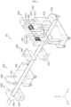
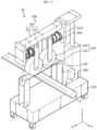
- FIG. 1 is a view showing the overall shape of a jig device 10 according to an embodiment of the present disclosure
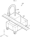
- FIG. 2 is a view showing a coating module 100 provided in the jig device 10 of FIG. 1
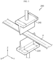
- FIG. 3 is a view showing a cutting module 200 provided in the jig device 10 of FIG. 1
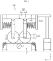
- FIG. 4 is a view showing a taping module 300 provided in the jig device 10 of FIG. 1 .
- the X-axis direction shown in the drawing may mean the horizontal direction of the workpiece P to be described later
- the Y-axis direction may mean the longitudinal direction (work progress direction) of the workpiece P perpendicular to the X-axis direction on a horizontal plane (XY plane)
- the Z-axis direction may mean a vertical direction perpendicular to both the X-axis direction and the Y-axis direction.
- a jig device 10 may include a coating module 100, a cutting module 200, and a taping module 300.
- the coating module 100 may be configured to coat the outer surface of the workpiece P with a coating material (not shown, e.g., paint).
- a coating material e.g., paint
- the workpiece P may be a pipe, a tube, a cable, or the like.
- the workpiece P may be used in a battery pack including at least one secondary battery.
- the workpiece P may be supplied to the jig device 10 at a constant speed through a separate workpiece supply device (not shown).
- the coating module 100 may include a cylinder unit 120 and a spray unit 140.
- the cylinder unit 120 may be connected to a coating material supply unit (not shown) provided outside to receive the coating material and provide a pumping force for spraying the coating material on the outer surface of the workpiece P to the spray unit 140.
- a coating material supply unit not shown
- the spray unit 140 may receive a coating material from the cylinder unit 120 and spray the coating material on the outer surface of the workpiece P.
- the spray unit 140 may be coupled to one side (e.g., an upper portion) of the cylinder unit 120.
- the cutting module 200 may be configured to cut the workpiece P.
- the cutting module 200 may include a first cutting unit 220 and a second cutting unit 240.
- the first cutting unit 220 may be disposed on the lower side of the workpiece P and particularly, may be connected to the ground.
- the second cutting unit 240 may be disposed on the upper side of the workpiece P. In this state, the first cutting unit 220 and the second cutting unit 240 may be driven in a vertical direction, respectively, to cut the workpiece P disposed between the first cutting unit 220 and the second cutting unit 240 in a vertical direction. Meanwhile, the front ends of the first cutting unit 220 and the second cutting unit 240 may be formed sharply to enable cutting of the workpiece P.
- the taping module 300 may be configured to tape the outer surface of the workpiece P.
- the taping module 300 may be configured to tape the outer surface of the workpiece P with a tape T.
- the tape T may be a sealing, a label, or the like.
- the jig device 10 of the present disclosure may be illustratively arranged in the order of the coating module 100, the cutting module 200, and the taping module 300 when viewed in the longitudinal direction (work progress direction) of the workpiece P, as shown in FIG. 1 .
- the coating module 100 may be disposed closer to the workpiece supply device than the cutting module 200 when viewed in the longitudinal direction of the workpiece P.
- the coating material may be coated on the outer surface of the workpiece P before cutting the workpiece P by this arrangement structure. Accordingly, it is possible to prevent damage to the woven workpiece P.
- the jig device 10 is arranged in the order of the coating module 100, the cutting module 200, and the taping module 300 when viewed in the longitudinal direction of the workpiece P, but is not limited thereto, and it may also be arranged in the order of the cutting module 200, the coating module 100, and the taping module 300. That is, after the cutting of the workpiece P by the cutting module 200, the coating of the workpiece P by the coating module 100 and the taping of the workpiece P by the taping module 300 may be performed sequentially.
- the jig device 10 may also be arranged in the order of the taping module 300, the coating module 100, and the cutting module 200 when viewed in the longitudinal direction of the workpiece P. That is, after the taping of the workpiece P by the taping module 300, the coating of the workpiece P by the coating module 100 and the cutting of the workpiece P by the cutting module 200 may be performed sequentially.
- the coating module 100, the cutting module 200, and the taping module 300 described above will be described in more detail.
- the coating module 100 may be configured to coat the outer surface of the workpiece P with a certain amount of coating material at regular intervals.
- the taping module 300 may be configured to tape the outer surface of the workpiece P with the tape T at regular intervals.
- the cylinder unit 120 of the coating module 100 may adjust the pumping force of the coating material so that the discharge pressure at the spray unit 140 remains constant so as to spray a certain amount of coating material on the outer surface of the workpiece P.
- the workpiece P may be supplied to the jig device 10 at a constant speed through a workpiece supply device (not shown).
- the coating module 100 and the taping module 300 may perform operations while moving at regular intervals with respect to the workpiece P, or may perform operations while remaining in place.
- the coating module 100 and the taping module 300 may be configured to move at a constant speed with respect to the workpiece P.
- the configuration of moving the coating module 100 and the taping module 300 with respect to the workpiece P will be described in more detail in the related description to be described later.
- the processing process of the workpiece P may be automated by the jig device 10, and the work completeness of the workpiece P may be improved.
- the coating module 100 may be configured to move along the workpiece P so as to coat the outer surface of the workpiece P with a coating material.
- the coating module 100 may further include a first position moving unit 160.
- the first position moving unit 160 may be disposed on the ground.
- the first position moving unit 160 may move the above-described cylinder unit 120 and spray unit 140 along the workpiece P.
- the first position moving unit 160 may be a structure including wheels for driving the cylinder unit 120 and the spray unit 140 along the workpiece P.
- the wheels of the first position moving unit 160 may be driven by a separate motor (not shown).
- the first position moving unit 160 may move the cylinder unit 120 and the spray unit 140 in at least one of the longitudinal direction and the horizontal direction of the workpiece P.
- the first position moving unit 160 may include a separate actuator driven in a vertical direction to drive the cylinder unit 120 and the spray unit 140 in a vertical direction.
- the cylinder unit 120 may be coupled to one side (e.g., an upper portion) of the first position moving unit 160.
- the first position moving unit 160 may move the cylinder unit 120 and the spray unit 140 at regular intervals in the longitudinal direction of the workpiece P.
- the coating process may be performed by the coating module 100 at a location preferred by the operator, and a rapid supplementary coating work may be performed for the portion where the coating of the coating material is insufficient on the outer surface of the workpiece P.
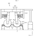
- FIG. 5 is a front view showing a portion of the taping module 300 of FIG. 4 .
- the taping module 300 may include a support frame 310, a pressure roller 320, and a tape supply unit 330.
- the support frame 310 may be configured to support the pressure roller 320.
- the pressure roller 320 may be coupled to the support frame 310 and may be configured to press the workpiece P so that the tape T is taped to the outer surface of the workpiece P. Specifically, the pressure roller 320 may be configured to be axially coupled to the support frame 310 to rotate.
- the tape supply unit 330 may be configured to supply the tape T to the pressure roller 320.
- the tape supply unit 330 may supply the tape T to the lower surface of the pressure roller 320.
- the tape T supplied by the tape supply unit 330 may be disposed to be in contact with the lower surface of the pressure roller 320.
- the support frame 310 may move the pressure roller 320 toward the workpiece P side by being driven up and down in a state where the tape T is supplied to the lower surface of the pressure roller 320.
- the workpiece P primarily wrapped with the tape T on its outer surface may be secondarily pressed by the pressure roller 320.
- the taping process is performed through the pressure roller 320 supported by the support frame 310, and thus the vibration of the pressure roller 320 may be minimized to perform a more stable taping process.
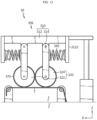
- FIGS. 6 to 8 are views showing a process of taping the workpiece P by the taping module 300 of FIG. 4 .
- FIG. 6 is a view showing a state in which the support frame 310 moves toward the workpiece P side
- FIG. 7 is a view showing a state in which the pressure roller 320 presses the workpiece P primarily wrapped with the tape T on its outer surface
- FIG. 8 is a view showing a state in which the tape T is taped on the outer surface of the workpiece P by the pressing force of the pressure roller 320.
- the pressure roller 320 may include a first roller 322 and a second roller 324.
- the first roller 322 may be coupled to the support frame 310.
- the second roller 324 may be disposed to face the first roller 322 in the horizontal direction (X-axis direction) of the workpiece P. Also, the second roller 324 may be coupled to the support frame 310.
- the support frame 310 may move the pressure roller 320 toward the workpiece P side by being driven up and down in a state where the tape T is supplied to the lower surface of the pressure roller 320.
- the first roller 322 and the second roller 324 may be configured to press the workpiece P located between the first roller 322 and the second roller 324 in the horizontal direction of the workpiece P.
- the outer surface of the workpiece P may be taped with the tape T by the pressing force of the first roller 322 and the second roller 324 between the first roller 322 and the second roller 324.
- the outer surface of the workpiece P passing between the first roller 322 and the second roller 324 may be uniformly taped with the tape T.
- the workpiece P wrapped with the tape T on its outer surface is pressed through the first roller 322 and the second roller 324 on both sides in the horizontal direction of the workpiece P, so that a more stable taping process may be performed.
- the support frame 310 may include a first frame 312 and a second frame 314.
- the first frame 312 may be formed by extending in the horizontal direction of the workpiece P.
- the second frame 314 is formed by extending in a vertical direction to be coupled to one side (e.g., a lower portion) in the vertical direction of the first frame 312, and may be configured to support the pressure roller 320.
- the second frame 314 may be provided as a pair of frames disposed to face each other in the horizontal direction of the workpiece P, and may be rotatably coupled to the first frame 312.
- the first roller 322 and the second roller 324 described above may be coupled to the pair of frames, respectively.
- the first frame 312 may further include an extension portion 3122 formed by extending in a vertical direction.
- the extension portion 3122 may be formed by extending downward from the first frame 312, and may be disposed to be spaced apart from the second frame 314 in the horizontal direction of the workpiece P.
- an elastic support unit 340 may be provided in the horizontal direction of the workpiece P.
- the elastic support unit 340 may be a spring, but is not limited thereto.
- the elastic support unit 340 may be configured to elastically support the second frame 314 in the horizontal direction of the workpiece P. Specifically, as shown in FIG. 7 , when the pressure roller 320 presses the workpiece P in the horizontal direction of the workpiece P, the elastic support unit 340 may be compressed to a predetermined length in the horizontal direction of the workpiece P. In addition, as shown in FIG. 8 , after the workpiece P taped on its outer surface with the tape T passes through the pressure roller 320, the elastic support unit 340 may return to its original state and elastically support the second frame 314 in the horizontal direction of the workpiece P. In this case, the support frame 310 including the first frame 312 and the second frame 314 may be made of a material having elasticity.
- damage to the support frame 310 may be prevented during the taping process of the workpiece P, and a more stable taping process may be performed.
- the support frame 310 may be configured to move in three axial directions of the workpiece P.
- the above-described taping module 300 may further include a second position moving unit 350.
- the second position moving unit 350 may be disposed on the ground.
- the second position moving unit 350 may move the support frame 310, the pressure roller 320, and the tape supply unit 330 described above in three axial directions of the workpiece P.
- the second position moving unit 350 may be a structure including wheels and actuators for driving the support frame 310, the pressure roller 320, and the tape supply unit 330 in three axial directions of the workpiece P.
- the wheels and actuators of the second position moving unit 350 may be driven by a separate motor (not shown).
- the second position moving unit 350 may move the support frame 310, the pressure roller 320, and the tape supply unit 330 in at least one of the longitudinal direction, horizontal direction, and vertical direction of the workpiece P.
- the support frame 310 may be connected to the second position moving unit 350.
- the second position moving unit 350 may move the support frame 310 at regular intervals in the longitudinal direction of the workpiece P.
- the taping process may be performed by the taping module 300 at a location preferred by the operator, and a rapid supplementary taping work may be performed for the portion where the taping is insufficient on the outer surface of the workpiece P.
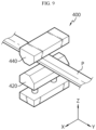
- FIG. 9 is a view showing a clamping module 400 provided in the jig device 10 of FIG. 1 .
- the jig device 10 may further include a clamping module 400.
- the clamping module 400 may be configured to fix the position of the workpiece P supplied to the jig device 10 at a constant speed.
- the clamping module 400 may be disposed closer to the workpiece supply device than the coating module 100, the cutting module 200, and the taping module 300 when viewed in the longitudinal direction (work progress direction) of the workpiece P.
- the clamping module 400 may include a first clamp 420 and a second clamp 440.
- the first clamp 420 is disposed on the lower side of the workpiece P, and may also be particularly disposed on the ground.
- the second clamp 440 may be disposed on the upper side of the workpiece P.
- the first clamp 420 and the second clamp 440 may be configured to be driven in a vertical direction, respectively, to fix the position of the workpiece P disposed between the first clamp 420 and the second clamp 440 in a vertical direction.
- the second clamp 440 may be driven through hydraulic pressure or pneumatic pressure.
- the coating module 100 may be configured to coat the outer surface of the workpiece P with a coating material in a state where the position of the workpiece P is fixed by the clamping module 400.
- the taping module 300 may be configured to tape the outer surface of the workpiece P with the tape T in a state where the position of the workpiece P is fixed by the clamping module 400.
- the shaking of the workpiece P is minimized by the clamping module 400, and thus a more stable coating process and taping process may be performed.
- the clamping module 400 may also be configured to move the workpiece P at a constant speed in a work progress direction by having a separate motor (not shown). Accordingly, the coating module 100 may coat the outer surface of the workpiece P with a coating material at regular intervals. In addition, the taping module 300 may tape the outer surface of the workpiece P with the tape T at regular intervals.
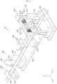
- FIG. 10 is a view showing a jig device 12 according to a second embodiment of the present disclosure.
- a jig device 12 according to a second embodiment of the present disclosure is illustrated. Since the jig device 12 according to this embodiment is similar to the jig device 10 of the previous embodiment, a redundant description of configurations substantially the same as or similar to those of the previous embodiment will be omitted, and hereinafter, differences from the previous embodiment will be mainly described.
- the coating module 102 and the taping module 302 provided in the jig device 12 may be disposed in plurality along the longitudinal direction (Y-axis direction) of the workpiece P, respectively.
- the distance between the plurality of coating modules 102 may be configured to be mutually adjustable. More specifically, the distance between the plurality of coating modules 102 may be mutually adjusted in the longitudinal direction (Y-axis direction) of the workpiece P. At this time, the distance between the plurality of coating modules 102 may be mutually adjusted according to the length of the workpiece P. In particular, the distance between the plurality of coating modules 102 may also be adjusted at the same interval.
- the distance between the plurality of taping modules 302 may be configured to be mutually adjustable. More specifically, the distance between the plurality of taping modules 302 may be mutually adjusted in the longitudinal direction (Y-axis direction) of the workpiece P. At this time, the distance between the plurality of taping modules 302 may be mutually adjusted according to the length of the workpiece P. In particular, the distance between the plurality of taping modules 302 may also be adjusted at the same interval.
- the coating process and the taping process may be performed at a plurality of positions of the workpiece P, and a supplementary work may be performed more rapidly for the portion where the coating process and the taping process are insufficient on the outer surface of the workpiece P.
- the jig device 12 may further include a first guide unit A1 and a second guide unit A2.
- the first guide unit A1 may be configured to guide the movement of the above-described first position moving unit 160 in the longitudinal direction of the workpiece P.
- the first guide unit A1 may be a linear motion guide (LM guide) and may be formed by extending in the longitudinal direction of the workpiece P.
- the first guide unit A1 may also be disposed on the ground.
- LM guide linear motion guide
- the second guide unit A2 may be configured to guide the movement of the above-described second position moving unit 350 in the longitudinal direction of the workpiece P.
- the second guide unit A2 may be a linear motion guide (LM guide) and may be formed by extending in the longitudinal direction of the workpiece P.
- the second guide unit A2 may also be disposed on the ground.
- LM guide linear motion guide
- the movement of the coating module 102 and the taping module 302 in the longitudinal direction of the workpiece P may be more stable. Therefore, it is possible to minimize a decrease in the completeness of the coating process and the taping process due to vibration generated by the movement of the coating module 102 and the taping module 302.
- the adjustment of mutual interval between the plurality of coating modules 102 and the plurality of taping modules 302 described above in the longitudinal direction of the workpiece P may be made more stably.
- FIG. 11 is a view showing a jig device 14 according to a third embodiment of the present disclosure.
- a jig device 14 according to a third embodiment of the present disclosure is illustrated. Since the jig device 14 according to this embodiment is similar to the jig device 10 of the previous embodiment, a redundant description of configurations substantially the same as or similar to those of the previous embodiment will be omitted, and hereinafter, differences from the previous embodiment will be mainly described.
- the jig device 14 may further include a base module 500.
- the base module 500 may be configured to support the coating module 104 and the taping module 304 provided in the jig device 14 with respect to the ground. That is, the coating module 104 and the taping module 304 may be integrally disposed on the base module 500 disposed on the ground.
- the first position moving unit 160 and the second position moving unit 350 may be configured to be driven only in a vertical direction, but is not limited thereto. Also, although not shown in FIG. 11 , the above-described first guide unit A1 and second guide unit A2 may also be located on the base module 500.
- the coating module 104 and the taping module 304 may be integrally disposed on the base module 500, and thus the overall vibration of the jig device 14 may be minimized compared to the case where the coating module 104 and the taping module 304 are each separately supported on the ground.
- FIG. 12 is a view showing a jig device 16 according to a fourth embodiment of the present disclosure.
- a jig device 16 according to a fourth embodiment of the present disclosure is illustrated. Since the jig device 16 according to this embodiment is similar to the jig device 10 of the previous embodiment, a redundant description of configurations substantially the same as or similar to those of the previous embodiment will be omitted, and hereinafter, differences from the previous embodiment will be mainly described.
- the taping module 306 provided in the jig device 16 may include a buffer pad 370.
- the buffer pad 370 may be provided on the outer surface of the pressure roller 320.
- the buffer pad 370 may buffer the pressing force applied to the workpiece P when the pressure roller 320 presses the workpiece P. Accordingly, damage to the workpiece P may be minimized during the process of taping the workpiece P.
- FIG. 13 is a view showing a jig device 18 according to a fifth embodiment of the present disclosure.
- a jig device 18 according to a fifth embodiment of the present disclosure is illustrated. Since the jig device 18 according to this embodiment is similar to the jig device 10 of the previous embodiment, a redundant description of configurations substantially the same as or similar to those of the previous embodiment will be omitted, and hereinafter, differences from the previous embodiment will be mainly described.
- the taping module 308 provided in the jig device 18 may include a tension control unit 380.
- the tension control unit 380 may be configured to adjust the tension of the tape T supplied to the pressure roller 320.
- the tension control unit 380 may be connected to the tape supply unit 330 and may be configured to adjust the tension of the tape T by supplying pneumatic pressure to the tape supply unit 330, but is not limited thereto.
- the tape T may be primarily adhered to the outer surface of the workpiece P more tightly before the pressure roller 320 presses the workpiece P, thereby further improving the completeness of the taping process.
- the process of processing the workpiece P may be automated by the jig devices 10, 12, 14, 16, 18.
Landscapes
- Engineering & Computer Science (AREA)
- Manufacturing & Machinery (AREA)
- Fixed Capacitors And Capacitor Manufacturing Machines (AREA)
- Lining Or Joining Of Plastics Or The Like (AREA)
Abstract
Description
- The present disclosure relates to a jig device, and more specifically, to a jig device capable of performing the cutting, coating, and taping processes of a workpiece in an integrated manner. The present application claims priority to
Korean Patent Application No. 10-2022-0069491 filed on June 8, 2022 - In general, a workpiece (e.g., a cable, a tube, a pipe, or the like) is cut directly by an operator without a separate device, or cut by a cutting device.
- In addition, the coating process and the taping process of the workpiece are performed directly by an operator without a separate coating device or taping device. In this case, there is a problem that the completeness of the coating process and the taping process is lowered and the production cost is increased.
- Specifically, when coating the workpiece, the coating amount of the coating material is not constant according to the skill level of the operator, and thus a product having a nonuniform coating thickness may be manufactured. In addition, when the workpiece is a woven workpiece, the workpiece is unwound during the cutting process, and thus the operator should directly perform the taping process. Accordingly, the completeness of taping for the workpiece is lowered and the production cost is greatly increased.
- The present disclosure is designed to solve the problems of the related art, and therefore the present disclosure is directed to providing a jig device capable of performing the cutting, coating, and taping processes of a workpiece in an integrated manner.
- However, technical problems to be solved by the present disclosure are not limited to the above-described problems, and other problems not mentioned herein may be clearly understood by those skilled in the art from the following description of the present disclosure.
- A jig device according to one aspect of the present disclosure for achieving the above-described object includes a coating module configured to coat the outer surface of a workpiece supplied at a constant speed with a coating material; a cutting module configured to cut the workpiece; and a taping module configured to tape the outer surface of the workpiece.
- Preferably, the coating module may be configured to coat the outer surface of the workpiece with a certain amount of coating material at regular intervals, and the taping module may be configured to tape the outer surface of the workpiece with a tape at regular intervals.
- Preferably, the coating module may be configured to move along the workpiece to coat the outer surface of the workpiece with a coating material.
- Preferably, the taping module may include a support frame; a pressure roller coupled to the support frame and configured to press the workpiece so that a tape is taped to the outer surface of the workpiece; and a tape supply unit configured to supply the tape to the pressure roller.
- Preferably, the pressure roller may include a first roller; and a second roller disposed to face the first roller in the horizontal direction of the workpiece, wherein the first roller and the second roller may be configured to press the workpiece positioned between the first roller and the second roller in the horizontal direction of the workpiece.
- Preferably, the support frame may include a first frame; and a second frame coupled to one side of the first frame in a vertical direction and configured to support the pressure roller, wherein the first frame may further include an extension portion formed by extending in a vertical direction, wherein an elastic support unit may be provided in the horizontal direction of the workpiece between the extension portion and the second frame, and the elastic support unit may be configured to elastically support the second frame in the horizontal direction of the workpiece.
- Preferably, the support frame may be configured to move in three axial directions of the workpiece.
- Preferably, the jig device may further include a clamping module configured to fix the position of the workpiece, wherein the coating module may be configured to coat the outer surface of the workpiece with a coating material in a state where the position of the workpiece is fixed, and the taping module may be configured to tape the outer surface of the workpiece with a tape in a state where the position of the workpiece is fixed.
- Preferably, the coating module and the taping module may be respectively disposed in plurality along the longitudinal direction of the workpiece, wherein the distance between the plurality of coating modules may be configured to be mutually adjustable, and the distance between the plurality of taping modules may be configured to be mutually adjustable.
- Preferably, the jig device may further include a base module configured to support the coating module and the taping module with respect to the ground.
- Preferably, the taping module may further include a buffer pad provided on the outer surface of the pressure roller.
- Preferably, the taping module may further include a tension control unit configured to adjust the tension of the tape supplied to the pressure roller.
- According to the embodiment of the present disclosure, it is possible to perform the cutting, coating, and taping processes of a workpiece in an integrated manner during the process of processing the workpiece, and the work completeness of the workpiece may be improved.
- In addition, several other additional effects may be achieved by various embodiments of the present disclosure. The various effects of the present disclosure will be described in detail in each embodiment, or descriptions of effects that may be easily understood by those skilled in the art will be omitted.
- The accompanying drawings illustrate a preferred embodiment of the present disclosure and together with the foregoing disclosure, serve to provide further understanding of the technical features of the present disclosure, and thus the present disclosure is not construed as being limited to the drawing.
-
FIG. 1 is a view showing the overall shape of a jig device according to an embodiment of the present disclosure. -
FIG. 2 is a view showing a coating module provided in the jig device ofFIG. 1 . -
FIG. 3 is a view showing a cutting module provided in the jig device ofFIG. 1 . -
FIG. 4 is a view showing a taping module provided in the jig device ofFIG. 1 . -
FIG. 5 is a front view showing a portion of the taping module ofFIG. 4 . -
FIGS. 6 to 8 are views showing a process of taping a workpiece by the taping module ofFIG. 4 . -
FIG. 9 is a view showing a clamping module provided in the jig device ofFIG. 1 . -
FIG. 10 is a view showing a jig device according to a second embodiment of the present disclosure. -
FIG. 11 is a view showing a jig device according to a third embodiment of the present disclosure. -
FIG. 12 is a view showing a jig device according to a fourth embodiment of the present disclosure. -
FIG. 13 is a view showing a jig device according to a fifth embodiment of the present disclosure. - Hereinafter, preferred embodiments of the present disclosure will be described in detail with reference to the accompanying drawings. Prior to the description, it should be understood that the terms used in the specification and the appended claims should not be construed as limited to general and dictionary meanings, but interpreted based on the meanings and concepts corresponding to technical aspects of the present disclosure on the basis of the principle that the inventor is allowed to define terms appropriately for the best explanation.
- Therefore, the description proposed herein is just a preferable example for the purpose of illustrations only, not intended to limit the scope of the disclosure, so it should be understood that other equivalents and modifications could be made thereto without departing from the scope of the disclosure.
-
FIG. 1 is a view showing the overall shape of ajig device 10 according to an embodiment of the present disclosure,FIG. 2 is a view showing acoating module 100 provided in thejig device 10 ofFIG. 1 ,FIG. 3 is a view showing acutting module 200 provided in thejig device 10 ofFIG. 1 , andFIG. 4 is a view showing ataping module 300 provided in thejig device 10 ofFIG. 1 . - In the embodiment of the present disclosure, the X-axis direction shown in the drawing may mean the horizontal direction of the workpiece P to be described later, the Y-axis direction may mean the longitudinal direction (work progress direction) of the workpiece P perpendicular to the X-axis direction on a horizontal plane (XY plane), and the Z-axis direction may mean a vertical direction perpendicular to both the X-axis direction and the Y-axis direction.
- Referring to
FIGS. 1 to 4 , ajig device 10 according to an embodiment of the present disclosure may include acoating module 100, acutting module 200, and ataping module 300. - The
coating module 100 may be configured to coat the outer surface of the workpiece P with a coating material (not shown, e.g., paint). In an embodiment, the workpiece P may be a pipe, a tube, a cable, or the like. In addition, the workpiece P may be used in a battery pack including at least one secondary battery. Also, the workpiece P may be supplied to thejig device 10 at a constant speed through a separate workpiece supply device (not shown). - More specifically, the
coating module 100 may include acylinder unit 120 and aspray unit 140. - The
cylinder unit 120 may be connected to a coating material supply unit (not shown) provided outside to receive the coating material and provide a pumping force for spraying the coating material on the outer surface of the workpiece P to thespray unit 140. - The
spray unit 140 may receive a coating material from thecylinder unit 120 and spray the coating material on the outer surface of the workpiece P. In addition, thespray unit 140 may be coupled to one side (e.g., an upper portion) of thecylinder unit 120. - The
cutting module 200 may be configured to cut the workpiece P. - Specifically, the
cutting module 200 may include afirst cutting unit 220 and asecond cutting unit 240. - The
first cutting unit 220 may be disposed on the lower side of the workpiece P and particularly, may be connected to the ground. In addition, thesecond cutting unit 240 may be disposed on the upper side of the workpiece P. In this state, thefirst cutting unit 220 and thesecond cutting unit 240 may be driven in a vertical direction, respectively, to cut the workpiece P disposed between thefirst cutting unit 220 and thesecond cutting unit 240 in a vertical direction. Meanwhile, the front ends of thefirst cutting unit 220 and thesecond cutting unit 240 may be formed sharply to enable cutting of the workpiece P. - The
taping module 300 may be configured to tape the outer surface of the workpiece P. In this case, thetaping module 300 may be configured to tape the outer surface of the workpiece P with a tape T. As an example, the tape T may be a sealing, a label, or the like. - The
jig device 10 of the present disclosure may be illustratively arranged in the order of thecoating module 100, thecutting module 200, and thetaping module 300 when viewed in the longitudinal direction (work progress direction) of the workpiece P, as shown inFIG. 1 . - Illustratively, if the workpiece P is formed of weaving, there is a high probability that the workpiece P is unwound and damaged when the woven workpiece P is cut by the
cutting module 200. To prevent this, in thejig device 10 of the present disclosure, thecoating module 100 may be disposed closer to the workpiece supply device than thecutting module 200 when viewed in the longitudinal direction of the workpiece P. Also, the coating material may be coated on the outer surface of the workpiece P before cutting the workpiece P by this arrangement structure. Accordingly, it is possible to prevent damage to the woven workpiece P. - Also, in
FIG. 1 , thejig device 10 is arranged in the order of thecoating module 100, thecutting module 200, and thetaping module 300 when viewed in the longitudinal direction of the workpiece P, but is not limited thereto, and it may also be arranged in the order of thecutting module 200, thecoating module 100, and thetaping module 300. That is, after the cutting of the workpiece P by thecutting module 200, the coating of the workpiece P by thecoating module 100 and the taping of the workpiece P by thetaping module 300 may be performed sequentially. - In addition, the
jig device 10 may also be arranged in the order of thetaping module 300, thecoating module 100, and thecutting module 200 when viewed in the longitudinal direction of the workpiece P. That is, after the taping of the workpiece P by thetaping module 300, the coating of the workpiece P by thecoating module 100 and the cutting of the workpiece P by thecutting module 200 may be performed sequentially. - According to this embodiment of the present disclosure, it is possible to perform the cutting, coating, and taping processes of the workpiece P in an integrated manner during the process of processing the workpiece P, and the work completeness of the workpiece P may be improved.
- Hereinafter, the
coating module 100, thecutting module 200, and thetaping module 300 described above will be described in more detail. - Referring to
FIGS. 1 to 4 again, thecoating module 100 may be configured to coat the outer surface of the workpiece P with a certain amount of coating material at regular intervals. In addition, thetaping module 300 may be configured to tape the outer surface of the workpiece P with the tape T at regular intervals. - Illustratively, the
cylinder unit 120 of thecoating module 100 may adjust the pumping force of the coating material so that the discharge pressure at thespray unit 140 remains constant so as to spray a certain amount of coating material on the outer surface of the workpiece P. - As described above, the workpiece P may be supplied to the
jig device 10 at a constant speed through a workpiece supply device (not shown). Illustratively, thecoating module 100 and thetaping module 300 may perform operations while moving at regular intervals with respect to the workpiece P, or may perform operations while remaining in place. At this time, when thecoating module 100 and thetaping module 300 perform operations while moving with respect to the workpiece P, thecoating module 100 and thetaping module 300 may be configured to move at a constant speed with respect to the workpiece P. Meanwhile, the configuration of moving thecoating module 100 and thetaping module 300 with respect to the workpiece P will be described in more detail in the related description to be described later. - According to this embodiment of the present disclosure, the processing process of the workpiece P may be automated by the
jig device 10, and the work completeness of the workpiece P may be improved. - Referring to
FIGS. 1 and2 again, thecoating module 100 may be configured to move along the workpiece P so as to coat the outer surface of the workpiece P with a coating material. - Specifically, the
coating module 100 may further include a firstposition moving unit 160. The firstposition moving unit 160 may be disposed on the ground. - The first
position moving unit 160 may move the above-describedcylinder unit 120 andspray unit 140 along the workpiece P. As shown inFIGS. 1 and2 , the firstposition moving unit 160 may be a structure including wheels for driving thecylinder unit 120 and thespray unit 140 along the workpiece P. In this case, the wheels of the firstposition moving unit 160 may be driven by a separate motor (not shown). Meanwhile, the firstposition moving unit 160 may move thecylinder unit 120 and thespray unit 140 in at least one of the longitudinal direction and the horizontal direction of the workpiece P. Also, although not shown, the firstposition moving unit 160 may include a separate actuator driven in a vertical direction to drive thecylinder unit 120 and thespray unit 140 in a vertical direction. In addition, thecylinder unit 120 may be coupled to one side (e.g., an upper portion) of the firstposition moving unit 160. - Also, the first
position moving unit 160 may move thecylinder unit 120 and thespray unit 140 at regular intervals in the longitudinal direction of the workpiece P. - According to this embodiment of the present disclosure, the coating process may be performed by the
coating module 100 at a location preferred by the operator, and a rapid supplementary coating work may be performed for the portion where the coating of the coating material is insufficient on the outer surface of the workpiece P. -
FIG. 5 is a front view showing a portion of thetaping module 300 ofFIG. 4 . - Referring to
FIGS. 1 and5 , thetaping module 300 may include asupport frame 310, apressure roller 320, and atape supply unit 330. - The
support frame 310 may be configured to support thepressure roller 320. - The
pressure roller 320 may be coupled to thesupport frame 310 and may be configured to press the workpiece P so that the tape T is taped to the outer surface of the workpiece P. Specifically, thepressure roller 320 may be configured to be axially coupled to thesupport frame 310 to rotate. - The
tape supply unit 330 may be configured to supply the tape T to thepressure roller 320. - In an embodiment, the
tape supply unit 330 may supply the tape T to the lower surface of thepressure roller 320. In this case, the tape T supplied by thetape supply unit 330 may be disposed to be in contact with the lower surface of thepressure roller 320. Also, thesupport frame 310 may move thepressure roller 320 toward the workpiece P side by being driven up and down in a state where the tape T is supplied to the lower surface of thepressure roller 320. - In this way, by the movement of the
support frame 310 toward the workpiece P side and the pressing force of thepressure roller 320, the workpiece P primarily wrapped with the tape T on its outer surface may be secondarily pressed by thepressure roller 320. - According to this embodiment of the present disclosure, the taping process is performed through the
pressure roller 320 supported by thesupport frame 310, and thus the vibration of thepressure roller 320 may be minimized to perform a more stable taping process. -
FIGS. 6 to 8 are views showing a process of taping the workpiece P by thetaping module 300 ofFIG. 4 . Specifically,FIG. 6 is a view showing a state in which thesupport frame 310 moves toward the workpiece P side,FIG. 7 is a view showing a state in which thepressure roller 320 presses the workpiece P primarily wrapped with the tape T on its outer surface, andFIG. 8 is a view showing a state in which the tape T is taped on the outer surface of the workpiece P by the pressing force of thepressure roller 320. - Referring to
FIGS. 5 to 8 , thepressure roller 320 may include afirst roller 322 and asecond roller 324. - The
first roller 322 may be coupled to thesupport frame 310. - The
second roller 324 may be disposed to face thefirst roller 322 in the horizontal direction (X-axis direction) of the workpiece P. Also, thesecond roller 324 may be coupled to thesupport frame 310. - Referring to
FIG. 6 , thesupport frame 310 may move thepressure roller 320 toward the workpiece P side by being driven up and down in a state where the tape T is supplied to the lower surface of thepressure roller 320. - Next, referring to
FIG. 7 , thefirst roller 322 and thesecond roller 324 may be configured to press the workpiece P located between thefirst roller 322 and thesecond roller 324 in the horizontal direction of the workpiece P. In this case, the outer surface of the workpiece P may be taped with the tape T by the pressing force of thefirst roller 322 and thesecond roller 324 between thefirst roller 322 and thesecond roller 324. - Also referring to
FIG. 8 , the outer surface of the workpiece P passing between thefirst roller 322 and thesecond roller 324 may be uniformly taped with the tape T. - According to this embodiment of the present disclosure, the workpiece P wrapped with the tape T on its outer surface is pressed through the
first roller 322 and thesecond roller 324 on both sides in the horizontal direction of the workpiece P, so that a more stable taping process may be performed. - Referring to
FIGS. 5 to 8 again, thesupport frame 310 may include afirst frame 312 and asecond frame 314. - The
first frame 312 may be formed by extending in the horizontal direction of the workpiece P. - The
second frame 314 is formed by extending in a vertical direction to be coupled to one side (e.g., a lower portion) in the vertical direction of thefirst frame 312, and may be configured to support thepressure roller 320. In this case, thesecond frame 314 may be provided as a pair of frames disposed to face each other in the horizontal direction of the workpiece P, and may be rotatably coupled to thefirst frame 312. Also, thefirst roller 322 and thesecond roller 324 described above may be coupled to the pair of frames, respectively. - Specifically, the
first frame 312 may further include anextension portion 3122 formed by extending in a vertical direction. In this case, theextension portion 3122 may be formed by extending downward from thefirst frame 312, and may be disposed to be spaced apart from thesecond frame 314 in the horizontal direction of the workpiece P. - In addition, between the
extension portion 3122 and thesecond frame 314, anelastic support unit 340 may be provided in the horizontal direction of the workpiece P. As an example, theelastic support unit 340 may be a spring, but is not limited thereto. - The
elastic support unit 340 may be configured to elastically support thesecond frame 314 in the horizontal direction of the workpiece P. Specifically, as shown inFIG. 7 , when thepressure roller 320 presses the workpiece P in the horizontal direction of the workpiece P, theelastic support unit 340 may be compressed to a predetermined length in the horizontal direction of the workpiece P. In addition, as shown inFIG. 8 , after the workpiece P taped on its outer surface with the tape T passes through thepressure roller 320, theelastic support unit 340 may return to its original state and elastically support thesecond frame 314 in the horizontal direction of the workpiece P. In this case, thesupport frame 310 including thefirst frame 312 and thesecond frame 314 may be made of a material having elasticity. - According to this embodiment of the present disclosure, damage to the
support frame 310 may be prevented during the taping process of the workpiece P, and a more stable taping process may be performed. - Referring to
FIGS. 1 and4 again, thesupport frame 310 may be configured to move in three axial directions of the workpiece P. - Specifically, the above-described
taping module 300 may further include a secondposition moving unit 350. The secondposition moving unit 350 may be disposed on the ground. - The second
position moving unit 350 may move thesupport frame 310, thepressure roller 320, and thetape supply unit 330 described above in three axial directions of the workpiece P. As shown inFIGS. 1 and4 , the secondposition moving unit 350 may be a structure including wheels and actuators for driving thesupport frame 310, thepressure roller 320, and thetape supply unit 330 in three axial directions of the workpiece P. In this case, the wheels and actuators of the secondposition moving unit 350 may be driven by a separate motor (not shown). Meanwhile, the secondposition moving unit 350 may move thesupport frame 310, thepressure roller 320, and thetape supply unit 330 in at least one of the longitudinal direction, horizontal direction, and vertical direction of the workpiece P. In addition, thesupport frame 310 may be connected to the secondposition moving unit 350. - Also, the second
position moving unit 350 may move thesupport frame 310 at regular intervals in the longitudinal direction of the workpiece P. - According to this embodiment of the present disclosure, the taping process may be performed by the
taping module 300 at a location preferred by the operator, and a rapid supplementary taping work may be performed for the portion where the taping is insufficient on the outer surface of the workpiece P. -
FIG. 9 is a view showing aclamping module 400 provided in thejig device 10 ofFIG. 1 . - Referring to
FIGS. 1 and9 , thejig device 10 may further include aclamping module 400. - The
clamping module 400 may be configured to fix the position of the workpiece P supplied to thejig device 10 at a constant speed. In this case, theclamping module 400 may be disposed closer to the workpiece supply device than thecoating module 100, thecutting module 200, and thetaping module 300 when viewed in the longitudinal direction (work progress direction) of the workpiece P. - Specifically, the
clamping module 400 may include afirst clamp 420 and asecond clamp 440. - The
first clamp 420 is disposed on the lower side of the workpiece P, and may also be particularly disposed on the ground. In addition, thesecond clamp 440 may be disposed on the upper side of the workpiece P. In this state, thefirst clamp 420 and thesecond clamp 440 may be configured to be driven in a vertical direction, respectively, to fix the position of the workpiece P disposed between thefirst clamp 420 and thesecond clamp 440 in a vertical direction. At this time, thesecond clamp 440 may be driven through hydraulic pressure or pneumatic pressure. - In this case, the
coating module 100 may be configured to coat the outer surface of the workpiece P with a coating material in a state where the position of the workpiece P is fixed by theclamping module 400. In addition, thetaping module 300 may be configured to tape the outer surface of the workpiece P with the tape T in a state where the position of the workpiece P is fixed by theclamping module 400. - According to this embodiment of the present disclosure, the shaking of the workpiece P is minimized by the
clamping module 400, and thus a more stable coating process and taping process may be performed. - Meanwhile, although not shown, the
clamping module 400 may also be configured to move the workpiece P at a constant speed in a work progress direction by having a separate motor (not shown). Accordingly, thecoating module 100 may coat the outer surface of the workpiece P with a coating material at regular intervals. In addition, thetaping module 300 may tape the outer surface of the workpiece P with the tape T at regular intervals. -
FIG. 10 is a view showing ajig device 12 according to a second embodiment of the present disclosure. - Referring to
FIG. 10 , ajig device 12 according to a second embodiment of the present disclosure is illustrated. Since thejig device 12 according to this embodiment is similar to thejig device 10 of the previous embodiment, a redundant description of configurations substantially the same as or similar to those of the previous embodiment will be omitted, and hereinafter, differences from the previous embodiment will be mainly described. - Referring to
FIG. 10 , thecoating module 102 and thetaping module 302 provided in thejig device 12 may be disposed in plurality along the longitudinal direction (Y-axis direction) of the workpiece P, respectively. - In this case, the distance between the plurality of
coating modules 102 may be configured to be mutually adjustable. More specifically, the distance between the plurality ofcoating modules 102 may be mutually adjusted in the longitudinal direction (Y-axis direction) of the workpiece P. At this time, the distance between the plurality ofcoating modules 102 may be mutually adjusted according to the length of the workpiece P. In particular, the distance between the plurality ofcoating modules 102 may also be adjusted at the same interval. - In addition, the distance between the plurality of taping
modules 302 may be configured to be mutually adjustable. More specifically, the distance between the plurality of tapingmodules 302 may be mutually adjusted in the longitudinal direction (Y-axis direction) of the workpiece P. At this time, the distance between the plurality of tapingmodules 302 may be mutually adjusted according to the length of the workpiece P. In particular, the distance between the plurality of tapingmodules 302 may also be adjusted at the same interval. - According to the
jig device 12 according to this embodiment, the coating process and the taping process may be performed at a plurality of positions of the workpiece P, and a supplementary work may be performed more rapidly for the portion where the coating process and the taping process are insufficient on the outer surface of the workpiece P. - Specifically, the
jig device 12 according to this embodiment may further include a first guide unit A1 and a second guide unit A2. - The first guide unit A1 may be configured to guide the movement of the above-described first
position moving unit 160 in the longitudinal direction of the workpiece P. As an example, the first guide unit A1 may be a linear motion guide (LM guide) and may be formed by extending in the longitudinal direction of the workpiece P. In this case, the first guide unit A1 may also be disposed on the ground. - The second guide unit A2 may be configured to guide the movement of the above-described second
position moving unit 350 in the longitudinal direction of the workpiece P. As an example, the second guide unit A2 may be a linear motion guide (LM guide) and may be formed by extending in the longitudinal direction of the workpiece P. In this case, the second guide unit A2 may also be disposed on the ground. - Accordingly, the movement of the
coating module 102 and thetaping module 302 in the longitudinal direction of the workpiece P may be more stable. Therefore, it is possible to minimize a decrease in the completeness of the coating process and the taping process due to vibration generated by the movement of thecoating module 102 and thetaping module 302. In addition, the adjustment of mutual interval between the plurality ofcoating modules 102 and the plurality of tapingmodules 302 described above in the longitudinal direction of the workpiece P may be made more stably. -
FIG. 11 is a view showing ajig device 14 according to a third embodiment of the present disclosure. - Referring to
FIG. 11 , ajig device 14 according to a third embodiment of the present disclosure is illustrated. Since thejig device 14 according to this embodiment is similar to thejig device 10 of the previous embodiment, a redundant description of configurations substantially the same as or similar to those of the previous embodiment will be omitted, and hereinafter, differences from the previous embodiment will be mainly described. - Referring to
FIG. 11 , thejig device 14 may further include abase module 500. - The
base module 500 may be configured to support thecoating module 104 and thetaping module 304 provided in thejig device 14 with respect to the ground. That is, thecoating module 104 and thetaping module 304 may be integrally disposed on thebase module 500 disposed on the ground. In the embodiment shown inFIG. 11 , the firstposition moving unit 160 and the secondposition moving unit 350 may be configured to be driven only in a vertical direction, but is not limited thereto. Also, although not shown inFIG. 11 , the above-described first guide unit A1 and second guide unit A2 may also be located on thebase module 500. - According to the
jig device 14 according to this embodiment, thecoating module 104 and thetaping module 304 may be integrally disposed on thebase module 500, and thus the overall vibration of thejig device 14 may be minimized compared to the case where thecoating module 104 and thetaping module 304 are each separately supported on the ground. -
FIG. 12 is a view showing ajig device 16 according to a fourth embodiment of the present disclosure. - Referring to
FIG. 12 , ajig device 16 according to a fourth embodiment of the present disclosure is illustrated. Since thejig device 16 according to this embodiment is similar to thejig device 10 of the previous embodiment, a redundant description of configurations substantially the same as or similar to those of the previous embodiment will be omitted, and hereinafter, differences from the previous embodiment will be mainly described. - Referring to
FIG. 12 , thetaping module 306 provided in thejig device 16 may include abuffer pad 370. - The
buffer pad 370 may be provided on the outer surface of thepressure roller 320. Thebuffer pad 370 may buffer the pressing force applied to the workpiece P when thepressure roller 320 presses the workpiece P. Accordingly, damage to the workpiece P may be minimized during the process of taping the workpiece P. -
FIG. 13 is a view showing ajig device 18 according to a fifth embodiment of the present disclosure. - Referring to
FIG. 13 , ajig device 18 according to a fifth embodiment of the present disclosure is illustrated. Since thejig device 18 according to this embodiment is similar to thejig device 10 of the previous embodiment, a redundant description of configurations substantially the same as or similar to those of the previous embodiment will be omitted, and hereinafter, differences from the previous embodiment will be mainly described. - Referring to
FIG. 13 , thetaping module 308 provided in thejig device 18 may include atension control unit 380. - In the
jig device 18 according to this embodiment, thetension control unit 380 may be configured to adjust the tension of the tape T supplied to thepressure roller 320. Thetension control unit 380 may be connected to thetape supply unit 330 and may be configured to adjust the tension of the tape T by supplying pneumatic pressure to thetape supply unit 330, but is not limited thereto. - According to this
tension control unit 380, the tape T may be primarily adhered to the outer surface of the workpiece P more tightly before thepressure roller 320 presses the workpiece P, thereby further improving the completeness of the taping process. - As described above, according to the embodiment of the present disclosure, it is possible to perform the cutting, coating, and taping processes of the workpiece P in an integrated manner during the process of processing the workpiece P, and the work completeness of the workpiece P may be improved. In addition, the process of processing the workpiece P may be automated by the
jig devices - While the present disclosure has been hereinabove described with regard to a limited number of embodiments and drawings, the present disclosure is not limited thereto and it is obvious to those skilled in the art that a variety of modifications and changes may be made thereto within the technical aspects of the present disclosure and the equivalent scope of the appended claims.
- Meanwhile, the terms indicating directions as used herein such as upper, lower, left, right, front, and rear are used for convenience of description only, and it is obvious to those skilled in the art that the term may change depending on the position of the stated element or an observer.
-
- 10, 12, 14, 16, 18: jig device
- 100, 102, 104: coating module
- 200: cutting module
- 300, 302, 304, 306, 308: taping module
- 310: support frame
- 312: first frame
- 3122: extension portion
- 314: second frame
- 320: pressure roller
- 322: first roller
- 324: second roller
- 330: tape supply unit
- 340: elastic support unit
- 370: buffer pad
- 380: tension control unit
- 400: clamping module
- 500: base module
- P: workpiece
- T: tape
Claims (12)
- A jig device comprising:a coating module configured to coat the outer surface of a workpiece supplied at a constant speed with a coating material;a cutting module configured to cut the workpiece; anda taping module configured to tape the outer surface of the workpiece.
- The jig device according to claim 1,wherein the coating module is configured to coat the outer surface of the workpiece with a certain amount of coating material at regular intervals, andthe taping module is configured to tape the outer surface of the workpiece with a tape at regular intervals.
- The jig device according to claim 1,
wherein the coating module is configured to move along the workpiece to coat the outer surface of the workpiece with a coating material. - The jig device according to claim 1,
wherein the taping module comprises:a support frame;a pressure roller coupled to the support frame and configured to press the workpiece so that a tape is taped to the outer surface of the workpiece; anda tape supply unit configured to supply the tape to the pressure roller. - The jig device according to claim 4,
wherein the pressure roller comprises:a first roller; anda second roller disposed to face the first roller in the horizontal direction of the workpiece,wherein the first roller and the second roller are configured to press the workpiece positioned between the first roller and the second roller in the horizontal direction of the workpiece. - The jig device according to claim 4,
wherein the support frame comprises:a first frame; anda second frame coupled to one side of the first frame in a vertical direction and configured to support the pressure roller,wherein the first frame further comprises an extension portion formed by extending in a vertical direction,wherein an elastic support unit is provided in the horizontal direction of the workpiece between the extension portion and the second frame, and the elastic support unit is configured to elastically support the second frame in the horizontal direction of the workpiece. - The jig device according to claim 4,
wherein the support frame is configured to move in three axial directions of the workpiece. - The jig device according to claim 1,which further comprises a clamping module configured to fix the position of the workpiece,wherein the coating module is configured to coat the outer surface of the workpiece with a coating material in a state where the position of the workpiece is fixed, andthe taping module is configured to tape the outer surface of the workpiece with a tape in a state where the position of the workpiece is fixed.
- The jig device according to claim 1,wherein the coating module and the taping module are respectively disposed in plurality along the longitudinal direction of the workpiece,wherein the distance between the plurality of coating modules is configured to be mutually adjustable, andthe distance between the plurality of taping modules is configured to be mutually adjustable.
- The jig device according to claim 1,
which further comprises a base module configured to support the coating module and the taping module with respect to the ground. - The jig device according to claim 4,
wherein the taping module further comprises a buffer pad provided on the outer surface of the pressure roller. - The jig device according to claim 4,
wherein the taping module further comprises a tension control unit configured to adjust the tension of the tape supplied to the pressure roller.
Applications Claiming Priority (2)
| Application Number | Priority Date | Filing Date | Title |
|---|---|---|---|
| KR1020220069491A KR102960847B1 (en) | 2022-06-08 | Jig device | |
| PCT/KR2023/007869 WO2023239180A1 (en) | 2022-06-08 | 2023-06-08 | Jig device |
Publications (2)
| Publication Number | Publication Date |
|---|---|
| EP4523801A1 true EP4523801A1 (en) | 2025-03-19 |
| EP4523801A4 EP4523801A4 (en) | 2025-09-24 |
Family
ID=89118686
Family Applications (1)
| Application Number | Title | Priority Date | Filing Date |
|---|---|---|---|
| EP23820115.6A Pending EP4523801A4 (en) | 2022-06-08 | 2023-06-08 | CLAMPING DEVICE |
Country Status (5)
| Country | Link |
|---|---|
| US (1) | US20250018706A1 (en) |
| EP (1) | EP4523801A4 (en) |
| JP (1) | JP7812463B2 (en) |
| CN (1) | CN118103147A (en) |
| WO (1) | WO2023239180A1 (en) |
Family Cites Families (16)
| Publication number | Priority date | Publication date | Assignee | Title |
|---|---|---|---|---|
| JPS5848348B2 (en) * | 1975-01-27 | 1983-10-27 | セキスイジユシ カブシキガイシヤ | Danmenshihoukeikiyoukakeshiyoushikannoseizohouhou |
| US4058427A (en) * | 1976-12-29 | 1977-11-15 | Midcon Pipeline Equipment Co. | Pipe wrapping apparatus |
| JPS54150446A (en) * | 1978-05-19 | 1979-11-26 | Koshuha Netsuren Kk | Continuous coating layer formation of unbonded pc steel rod and apparatus therefor |
| JPS57100034A (en) * | 1980-12-15 | 1982-06-22 | Furukawa Electric Co Ltd:The | Manufacture of composite insulating tube |
| JPS59145114A (en) * | 1983-02-08 | 1984-08-20 | Fuji Seal Kogyo Kk | Manufacture of paper tube coated with heat shrinkable synthetic resin film |
| US4946528A (en) * | 1987-11-18 | 1990-08-07 | Kawasaki Steel Corporation | Method and equipment for producing protective-coated steel pipe |
| JPH02158322A (en) * | 1988-12-13 | 1990-06-18 | Sekisui Chem Co Ltd | Method and apparatus for manufacture of resin composite tube and coupling member used therefor |
| US5417786A (en) * | 1993-04-12 | 1995-05-23 | Denman; George W. | Apparatus and method for coating and wrapping pipe |
| JP3418369B2 (en) * | 2000-06-14 | 2003-06-23 | 雅彦 勝山 | Coating roller and its manufacturing method |
| JP2005507329A (en) * | 2001-10-31 | 2005-03-17 | エーディーシー アクイジション カンパニー | Method for producing reinforced thermoplastic pipe |
| FR2873952B1 (en) * | 2004-08-06 | 2008-07-04 | Fibres Et Carbone Sa Soc D | REINFORCED ELONGATED ELEMENTS SUCH AS TUBES, METHOD AND APPARATUS FOR MANUFACTURING |
| KR100988150B1 (en) * | 2010-04-23 | 2010-10-18 | 유근식 | Side sealing apparatus of tube |
| KR101375975B1 (en) * | 2013-04-17 | 2014-04-01 | 주성철 | Shielding apparatus for flat cable |
| KR102226492B1 (en) * | 2019-01-28 | 2021-03-11 | (주) 피토 | Tape attaching apparatus for jelly roll of secondary battery and tape attaching method using same |
| KR102801385B1 (en) * | 2020-01-22 | 2025-04-28 | 엘에스전선 주식회사 | Pating appararus for cable |
| KR102430993B1 (en) | 2020-11-20 | 2022-08-11 | 한국에너지기술연구원 | Metal coating catalyst for electric-field assisted, Manufacturing method for the same and Syngas production method using the same |
-
2023
- 2023-06-08 WO PCT/KR2023/007869 patent/WO2023239180A1/en not_active Ceased
- 2023-06-08 US US18/713,027 patent/US20250018706A1/en active Pending
- 2023-06-08 EP EP23820115.6A patent/EP4523801A4/en active Pending
- 2023-06-08 JP JP2024562341A patent/JP7812463B2/en active Active
- 2023-06-08 CN CN202380014008.0A patent/CN118103147A/en active Pending
Also Published As
| Publication number | Publication date |
|---|---|
| JP7812463B2 (en) | 2026-02-09 |
| JP2025514107A (en) | 2025-05-02 |
| US20250018706A1 (en) | 2025-01-16 |
| CN118103147A (en) | 2024-05-28 |
| EP4523801A4 (en) | 2025-09-24 |
| KR20230168792A (en) | 2023-12-15 |
| WO2023239180A1 (en) | 2023-12-14 |
Similar Documents
| Publication | Publication Date | Title |
|---|---|---|
| KR102269811B1 (en) | Automatic connection apparatus for film type material of secondary battery | |
| US20110180210A1 (en) | Pressure bonding apparatus and method | |
| CN104608458A (en) | Joint linking machine and joint linking method | |
| KR102923040B1 (en) | Glass mounting device and method | |
| CN105163513A (en) | Flexible circuit board chip mounter | |
| US20250018706A1 (en) | Jig device | |
| EP0919323B1 (en) | Part supplying device and method for supplying parts using the same device | |
| CN111283290B (en) | Automatic welding machine | |
| TW201919831A (en) | Robot hand, robot device, and method for manufacturing electronic apparatus | |
| KR102960847B1 (en) | Jig device | |
| CN216807061U (en) | Special-shaped steel wire vibrations material feeding unit | |
| KR100794708B1 (en) | Tape attaching device of “ㄷ” shaped part | |
| US20180305062A1 (en) | Device and method for labeling individual packages | |
| KR100815464B1 (en) | LCD panel protective film attachment device | |
| CN212350696U (en) | Automatic welding machine | |
| CN217456435U (en) | Full-automatic tape winding machine | |
| CN112477093B (en) | Film sticking equipment and film sticking method | |
| CN214114129U (en) | Anchor clamps and material loading machine | |
| KR100765175B1 (en) | Angular spot tape attachment system | |
| CN217702407U (en) | Full-automatic manipulator feed mechanism | |
| CN114229151A (en) | Film tearing equipment | |
| KR20040006224A (en) | Bonding Equipment For Anisotropic Conductive Film And Drive Chip Of Flat Panel Display | |
| CN208961382U (en) | A kind of copper foil adhering device | |
| WO2006083404B1 (en) | Wire bonding apparatus | |
| CN111071521A (en) | Coating equipment |
Legal Events
| Date | Code | Title | Description |
|---|---|---|---|
| STAA | Information on the status of an ep patent application or granted ep patent |
Free format text: STATUS: THE INTERNATIONAL PUBLICATION HAS BEEN MADE |
|
| PUAI | Public reference made under article 153(3) epc to a published international application that has entered the european phase |
Free format text: ORIGINAL CODE: 0009012 |
|
| STAA | Information on the status of an ep patent application or granted ep patent |
Free format text: STATUS: REQUEST FOR EXAMINATION WAS MADE |
|
| 17P | Request for examination filed |
Effective date: 20241210 |
|
| AK | Designated contracting states |
Kind code of ref document: A1 Designated state(s): AL AT BE BG CH CY CZ DE DK EE ES FI FR GB GR HR HU IE IS IT LI LT LU LV MC ME MK MT NL NO PL PT RO RS SE SI SK SM TR |
|
| DAV | Request for validation of the european patent (deleted) | ||
| DAX | Request for extension of the european patent (deleted) | ||
| A4 | Supplementary search report drawn up and despatched |
Effective date: 20250822 |
|
| RIC1 | Information provided on ipc code assigned before grant |
Ipc: B05C 13/02 20060101AFI20250819BHEP Ipc: B05C 11/02 20060101ALI20250819BHEP Ipc: B05C 1/04 20060101ALI20250819BHEP Ipc: B65H 35/00 20060101ALI20250819BHEP Ipc: B29C 63/00 20060101ALI20250819BHEP Ipc: B29C 63/02 20060101ALI20250819BHEP Ipc: B29C 63/48 20060101ALN20250819BHEP |