EP4523767A1 - Spielprogramm, spielverarbeitungssystem, spielverarbeitungsgerät und spielverarbeitungsverfahren - Google Patents
Spielprogramm, spielverarbeitungssystem, spielverarbeitungsgerät und spielverarbeitungsverfahren Download PDFInfo
- Publication number
- EP4523767A1 EP4523767A1 EP24153725.7A EP24153725A EP4523767A1 EP 4523767 A1 EP4523767 A1 EP 4523767A1 EP 24153725 A EP24153725 A EP 24153725A EP 4523767 A1 EP4523767 A1 EP 4523767A1
- Authority
- EP
- European Patent Office
- Prior art keywords
- game
- player character
- objects
- processor
- character object
- Prior art date
- Legal status (The legal status is an assumption and is not a legal conclusion. Google has not performed a legal analysis and makes no representation as to the accuracy of the status listed.)
- Pending
Links
Images







Classifications
-
- A—HUMAN NECESSITIES
- A63—SPORTS; GAMES; AMUSEMENTS
- A63F—CARD, BOARD, OR ROULETTE GAMES; INDOOR GAMES USING SMALL MOVING PLAYING BODIES; VIDEO GAMES; GAMES NOT OTHERWISE PROVIDED FOR
- A63F13/00—Video games, i.e. games using an electronically generated display having two or more dimensions
- A63F13/50—Controlling the output signals based on the game progress
- A63F13/52—Controlling the output signals based on the game progress involving aspects of the displayed game scene
-
- A—HUMAN NECESSITIES
- A63—SPORTS; GAMES; AMUSEMENTS
- A63F—CARD, BOARD, OR ROULETTE GAMES; INDOOR GAMES USING SMALL MOVING PLAYING BODIES; VIDEO GAMES; GAMES NOT OTHERWISE PROVIDED FOR
- A63F13/00—Video games, i.e. games using an electronically generated display having two or more dimensions
- A63F13/55—Controlling game characters or game objects based on the game progress
- A63F13/57—Simulating properties, behaviour or motion of objects in the game world, e.g. computing tyre load in a car race game
-
- A—HUMAN NECESSITIES
- A63—SPORTS; GAMES; AMUSEMENTS
- A63F—CARD, BOARD, OR ROULETTE GAMES; INDOOR GAMES USING SMALL MOVING PLAYING BODIES; VIDEO GAMES; GAMES NOT OTHERWISE PROVIDED FOR
- A63F13/00—Video games, i.e. games using an electronically generated display having two or more dimensions
- A63F13/50—Controlling the output signals based on the game progress
- A63F13/52—Controlling the output signals based on the game progress involving aspects of the displayed game scene
- A63F13/525—Changing parameters of virtual cameras
-
- A—HUMAN NECESSITIES
- A63—SPORTS; GAMES; AMUSEMENTS
- A63F—CARD, BOARD, OR ROULETTE GAMES; INDOOR GAMES USING SMALL MOVING PLAYING BODIES; VIDEO GAMES; GAMES NOT OTHERWISE PROVIDED FOR
- A63F13/00—Video games, i.e. games using an electronically generated display having two or more dimensions
- A63F13/55—Controlling game characters or game objects based on the game progress
Definitions
- the present disclosure relates to information processing of a game or the like.
- an object of the exemplary embodiment is to provide a game program, a game processing system, a game processing apparatus, and a game processing method that enable such an image expression that a character sufficiently appears to be on a near side or a far side while a game space is drawn by orthographic projection.
- a first configuration example is a game program configured to cause a processor of an information processing apparatus to: in a virtual space where at least a player character object and terrain objects are placed, control at least the player character object and a virtual camera; and draw, in a frame buffer, objects in the virtual space, on the basis of orthographic projection, and further, in a first scene in a game, perform drawing while performing, by a vertex shader, such transformation that, among the objects in the virtual space, at least the player character object and one or some of the terrain objects are moved to a near side and are enlarged, or are moved to a far side and are reduced.
- objects are enlarged or reduced by the vertex shader in drawing the virtual space by orthographic projection.
- a scene in which the objects are placed on the near side or the far side can be expressed, whereby a sense of depth in the game image can be effectively provided.
- the objects are enlarged or reduced by the vertex shader in drawing the virtual space.
- it is not necessary to correct game processing for collision detection or the like in accordance with enlargement or reduction of the objects present in the virtual space.
- the game program causes the professor to: cause a first terrain object to appear in a case where a first condition in the game is satisfied on the basis of control for the player character object; and in the first scene that is a subsequent scene, perform drawing while performing the transformation for the player character object and the first terrain object.
- the game program causes the professor to: draw, in the frame buffer, the objects in the virtual space, on the basis of orthographic projection, and further, perform drawing while performing the transformation for a second terrain object among the objects in the virtual space; move the player character object in a case where a second condition in the game is satisfied on the basis of control for the player character object; and in the first scene that is a subsequent scene, further perform drawing while performing the transformation for the player character object.
- the game program causes the professor to: draw, in the frame buffer, the objects in the virtual space, while performing a depth test; and on an image drawn in the frame buffer, further impart, on the basis of a depth in a depth buffer, a predetermined effect that is based on a pixel in a second range excluding a first range in which the depth is small.
- the predetermined effect can be imparted only in a far-side range of the game image.
- characters moved to and drawn on the far side are also subjected to the predetermined effect, whereby a sense of depth can be provided.
- the predetermined effect is a bloom effect.
- the game program causes the professor to: in a case of adding a color to a pixel in the first range by the bloom effect that is based on the pixel in the second range, correct the color to be added, on the basis of at least exponentiation, and then add the corrected color.
- a game program it is possible to provide a game program, a game processing system, a game processing apparatus, and a game processing method that enable such an image expression that a character sufficiently appears to be on a near side or a far side while a game space is drawn by orthographic projection.
- An example of a game system 1 according to the exemplary embodiment includes a main body apparatus (an information processing apparatus, which functions as a game apparatus main body in the exemplary embodiment) 2, a left controller 3, and a right controller 4.
- a main body apparatus an information processing apparatus, which functions as a game apparatus main body in the exemplary embodiment
- a left controller 3 and a right controller 4 are attachable to and detachable from the main body apparatus 2. That is, the game system 1 can be used as a unified apparatus obtained by attaching each of the left controller 3 and the right controller 4 to the main body apparatus 2.
- the main body apparatus 2, the left controller 3, and the right controller 4 can also be used as separate bodies.
- the hardware configuration of the game system 1 according to the exemplary embodiment will be described, and then, the control of the game system 1 according to the exemplary embodiment will be described.
- FIG. 1 shows an example of the state where the left controller 3 and the right controller 4 are attached to the main body apparatus 2. As shown in FIG. 1 , each of the left controller 3 and the right controller 4 is attached to and unified with the main body apparatus 2.
- the main body apparatus 2 is an apparatus for performing various processes in the game system 1.
- the main body apparatus 2 includes a display 12.
- Each of the left controller 3 and the right controller 4 is an apparatus including operation sections with which a user provides inputs.
- the main body apparatus 2 also includes speakers 88, and sounds such as sound effects are outputted from the speakers 88.
- the main body apparatus 2 also includes a left terminal 17 for the main body apparatus 2 to perform wired communication with the left controller 3, and a right terminal 21 for the main body apparatus 2 to perform wired communication with the right controller 4.
- the main body apparatus 2 also includes a slot 23.
- the slot 23 is provided on an upper side surface of a housing of the main body apparatus 2.
- the slot 23 is so shaped as to allow a predetermined type of storage medium to be attached to the slot 23.
- the predetermined type of storage medium is, for example, a dedicated storage medium (e.g., a dedicated memory card) for the game system 1 and an information processing apparatus of the same type as the game system 1.
- the predetermined type of storage medium is used to store, for example, data (e.g., saved data of an application or the like) used by the main body apparatus 2 and/or a program (e.g., a program for an application or the like) executed by the main body apparatus 2.
- Each of the left controller 3 and the right controller 4 includes various operation buttons, etc.
- the various operation buttons, etc. are used to give instructions according to various programs (e.g., an OS program and an application program) executed by the main body apparatus 2.
- Each of the left controller 3 and the right controller 4 also includes a terminal 42 or 64 for performing wired communication with the main body apparatus 2.
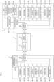
- FIG. 2 is a block diagram showing an example of the internal configuration of the main body apparatus 2.
- the main body apparatus 2 includes a processor 81.
- the processor 81 is an information processing section for executing various types of information processing to be executed by the main body apparatus 2.
- the processor 81 may be composed of a SoC (System-on-a-chip) having a plurality of functions such as a CPU (Central Processing Unit) function and a GPU (Graphics Processing Unit) function.
- the processor 81 executes an information processing program (e.g., a game program) stored in a storage section (specifically, an internal storage medium such as a flash memory 84, an external storage medium attached to the slot 23, or the like), thereby performing the various types of information processing.
- a storage section specifically, an internal storage medium such as a flash memory 84, an external storage medium attached to the slot 23, or the like
- the main body apparatus 2 includes the flash memory 84 and a DRAM (Dynamic Random Access Memory) 85 as examples of internal storage media built into the main body apparatus 2.
- the flash memory 84 and the DRAM 85 are connected to the processor 81.
- the flash memory 84 is a memory mainly used to store various data (or programs) to be saved in the main body apparatus 2.
- the DRAM 85 is a memory used to temporarily store various data used for information processing.
- the main body apparatus 2 includes a slot interface (hereinafter, abbreviated as "I/F") 91.
- the slot I/F 91 is connected to the processor 81.
- the slot I/F 91 is connected to the slot 23, and in accordance with an instruction from the processor 81, reads and writes data from and to the predetermined type of storage medium (e.g., a dedicated memory card) attached to the slot 23.
- the predetermined type of storage medium e.g., a dedicated memory card
- the processor 81 appropriately reads and writes data from and to the flash memory 84, the DRAM 85, and each of the above storage media, thereby performing the above information processing.
- the main body apparatus 2 includes a network communication section 82.
- the network communication section 82 is connected to the processor 81.
- the network communication section 82 communicates (specifically, through wireless communication) with an external apparatus via a network.
- the network communication section 82 connects to a wireless LAN by a method compliant with the Wi-Fi standard, for example, and performs Internet communication or the like with an external apparatus (another main body apparatus 2).
- the network communication section 82 can also perform short-range wireless communication (e.g., infrared light communication) with another main body apparatus 2.
- the main body apparatus 2 includes a controller communication section 83.
- the controller communication section 83 is connected to the processor 81.
- the controller communication section 83 wirelessly communicates with the left controller 3 and/or the right controller 4.
- the communication method between the main body apparatus 2, and the left controller 3 and the right controller 4, is discretionary.
- the controller communication section 83 performs communication compliant with the Bluetooth (registered trademark) standard with the left controller 3 and with the right controller 4.
- the processor 81 is connected to the above left terminal 17, the above right terminal 21, and a lower terminal 27.
- the processor 81 transmits data to the left controller 3 via the left terminal 17 and also receives operation data from the left controller 3 via the left terminal 17.
- the processor 81 transmits data to the right controller 4 via the right terminal 21 and also receives operation data from the right controller 4 via the right terminal 21.
- the processor 81 transmits data to the cradle via the lower terminal 27.
- the main body apparatus 2 can perform both wired communication and wireless communication with each of the left controller 3 and the right controller 4.
- the main body apparatus 2 can output data (e.g., image data or sound data) to the stationary monitor or the like via the cradle.
- data e.g., image data or sound data
- the main body apparatus 2 includes a touch panel controller 86, which is a circuit for controlling a touch panel 13.
- the touch panel controller 86 is connected between the touch panel 13 and the processor 81. On the basis of a signal from the touch panel 13, the touch panel controller 86 generates data indicating the position at which a touch input has been performed, for example, and outputs the data to the processor 81.
- the display 12 is connected to the processor 81.
- the processor 81 displays a generated image (e.g., an image generated by executing the above information processing) and/or an externally acquired image on the display 12.
- the main body apparatus 2 includes a codec circuit 87 and the speakers (specifically, a left speaker and a right speaker) 88.
- the codec circuit 87 is connected to the speakers 88 and a sound input/output terminal 25 and also connected to the processor 81.
- the codec circuit 87 is a circuit for controlling the input and output of sound data to and from the speakers 88 and the sound input/output terminal 25.
- the main body apparatus 2 includes a power control section 97 and a battery 98.
- the power control section 97 is connected to the battery 98 and the processor 81. Further, although not shown in FIG. 6 , the power control section 97 is connected to components of the main body apparatus 2 (specifically, components that receive power supplied from the battery 98, the left terminal 17, and the right terminal 21). On the basis of a command from the processor 81, the power control section 97 controls the supply of power from the battery 98 to the above components.
- the battery 98 is connected to the lower terminal 27.
- an external charging device e.g., the cradle
- the battery 98 is charged with the supplied power.
- FIG. 3 is a block diagram showing examples of the internal configurations of the main body apparatus 2, the left controller 3, and the right controller 4. It should be noted that the details of the internal configuration of the main body apparatus 2 are shown in FIG. 2 and therefore are omitted in FIG. 3 .
- the left controller 3 includes a communication control section 101, which communicates with the main body apparatus 2. As shown in FIG. 3 , the communication control section 101 is connected to components including the terminal 42. In the exemplary embodiment, the communication control section 101 can communicate with the main body apparatus 2 through both wired communication via the terminal 42 and wireless communication not via the terminal 42.
- the communication control section 101 controls the method for communication performed by the left controller 3 with the main body apparatus 2. That is, when the left controller 3 is attached to the main body apparatus 2, the communication control section 101 communicates with the main body apparatus 2 via the terminal 42. Further, when the left controller 3 is detached from the main body apparatus 2, the communication control section 101 wirelessly communicates with the main body apparatus 2 (specifically, the controller communication section 83).
- the wireless communication between the communication control section 101 and the controller communication section 83 is performed in accordance with the Bluetooth (registered trademark) standard, for example.
- the left controller 3 also includes a memory 102 such as a flash memory.
- the communication control section 101 includes, for example, a microcomputer (or a microprocessor) and executes firmware stored in the memory 102, thereby performing various processes.
- the left controller 3 includes buttons 103.
- the left controller 3 also includes a left stick 32.
- Each of the buttons 103 and the left stick 32 outputs information regarding an operation performed on itself to the communication control section 101 repeatedly at appropriate timings.
- the left controller 3 includes inertial sensors. Specifically, the left controller 3 includes an acceleration sensor 104. Further, the left controller 3 includes an angular velocity sensor 105.
- the acceleration sensor 104 detects the magnitudes of accelerations along predetermined three axial (e.g., xyz axes shown in FIG. 1 ) directions. It should be noted that the acceleration sensor 104 may detect an acceleration along one axial direction or accelerations along two axial directions.
- the angular velocity sensor 105 detects angular velocities about predetermined three axes (e.g., the xyz axes shown in FIG. 1 ).
- the angular velocity sensor 105 may detect an angular velocity about one axis or angular velocities about two axes.
- Each of the acceleration sensor 104 and the angular velocity sensor 105 is connected to the communication control section 101. Then, the detection results of the acceleration sensor 104 and the angular velocity sensor 105 are outputted to the communication control section 101 repeatedly at appropriate timings.
- the communication control section 101 acquires information regarding an input (specifically, information regarding an operation, or the detection result of the sensor) from each of input sections (specifically, the buttons 103, the left stick 32, and the sensors 104 and 105).
- the communication control section 101 transmits operation data including the acquired information (or information obtained by performing predetermined processing on the acquired information) to the main body apparatus 2. It should be noted that the operation data is transmitted repeatedly, once every predetermined time. It should be noted that the interval at which the information regarding an input is transmitted from each of the input sections to the main body apparatus 2 may or may not be the same.
- the above operation data is transmitted to the main body apparatus 2, whereby the main body apparatus 2 can obtain inputs provided to the left controller 3. That is, the main body apparatus 2 can determine operations on the buttons 103 and the left stick 32 on the basis of the operation data. Further, the main body apparatus 2 can calculate information regarding the motion and/or the orientation of the left controller 3 on the basis of the operation data (specifically, the detection results of the acceleration sensor 104 and the angular velocity sensor 105).
- the left controller 3 includes a power supply section 108.
- the power supply section 108 includes a battery and a power control circuit.
- the power control circuit is connected to the battery and also connected to components of the left controller 3 (specifically, components that receive power supplied from the battery).
- the right controller 4 includes a communication control section 111, which communicates with the main body apparatus 2.
- the right controller 4 also includes a memory 112 which is connected to the communication control section 111.
- the communication control section 111 is connected to components including the terminal 64.
- the communication control section 111 and the memory 112 have functions similar to those of the communication control section 101 and the memory 102, respectively, of the left controller 3.
- the communication control section 111 can communicate with the main body apparatus 2 through both wired communication via the terminal 64 and wireless communication not via the terminal 64 (specifically, communication compliant with the Bluetooth (registered trademark) standard).
- the communication control section 111 controls the method for communication performed by the right controller 4 with the main body apparatus 2.
- the right controller 4 includes input sections similar to the input sections of the left controller 3. Specifically, the right controller 4 includes buttons 113, a right stick 52, and inertial sensors (an acceleration sensor 114 and an angular velocity sensor 115). These input sections have functions similar to those of the input sections of the left controller 3 and operate similarly to the input sections of the left controller 3.
- the right controller 4 includes a power supply section 118.
- the power supply section 118 has a function similar to that of the power supply section 108 of the left controller 3 and operates similarly to the power supply section 108.
- a game assumed in the exemplary embodiment is such an action game that, in a virtual space (game space) where various objects are placed, a player character object (which may be referred to as a "player character") acting in accordance with an operation by a player (user) moves to reach a goal point.
- a player character object which may be referred to as a "player character”
- an image of the game space is taken by a virtual camera using orthographic projection (parallel projection), and a game image as in a two-dimensional game is displayed on a screen (display 12).
- This game is not limited to such an action game and may be another type of game.
- FIG. 4 shows an example of a game screen in this game.
- a terrain object A a terrain object B, and a terrain object C are displayed on the game screen.
- one enemy character object which may be referred to as an "enemy character” 201
- one player character 200 and one entrance/exit object (which may be simply referred to as an "entrance/exit") 205 are displayed.
- On the terrain object B two enemy characters 201, one entrance/exit 202, and one entrance/exit 203 are displayed.
- the terrain object A and an object displayed on the terrain object A may be referred to as a "layer A”
- the terrain object B and an object displayed on the terrain object B may be referred to as a "layer B”
- the terrain object C and an object displayed on the terrain object C may be referred to as a "layer C”.
- the player operates the player character 200 to move the player character 200, heading toward a goal point (not shown) located rightward (in an increase direction of x axis).
- a goal point not shown
- the layer A, the layer B, and the layer C are displayed while being side-scrolled so that the player character 200 does not go out of the display range of the screen.
- the player character 200 contacts with the enemy character 201, the player character 200 takes damage.
- the enemy characters 201 are the same kind of enemy characters and have the same size in the game space.
- the trees 210 are also the same kind of trees and have the same size in the game space.
- the entrance/exit 203 and the entrance/exit 205 have the same size in the game space, and the entrance/exits 202 and 204 also have the same size in the game space.
- the layer A displayed on the nearest side is displayed in an enlarged manner, and the layer C displayed on the farthest side is displayed in a reduced manner.
- a layer on a near side and a layer on a far side are displayed in the same size (same magnification), so that a sense of depth as in FIG. 4 is not provided.
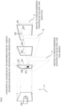
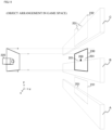
- FIG. 5 illustrates the game space whose image is taken for drawing the game screen (game image) shown in FIG. 4 .
- a virtual camera 220 and the terrain objects A to C are placed in the game space.
- the terrain objects A to C are arranged so as to be aligned in the up-down direction (y-axis direction) at an equal depth position (same distance in the z direction) from the virtual camera 220, in the game space.
- On the upper side (increase direction of y axis) of the terrain object A one enemy character 201 and one player character 200 are placed.
- y-axis direction the up-down direction
- the terrain objects are shown in plate shapes
- the enemy characters 201 and the player character 200 are shown in elliptic shapes
- objects such as the trees and the entrance/exits are not shown.
- the depths of the terrain objects A to C in the game space and the depths of the characters on the terrain objects are the same, but may be different from each other.
- FIG. 5 a rectangular area 230 of the terrain object B whose image is taken by the virtual camera 220 using orthographic projection, is shown.
- a rectangular area 231 having the same size as the area 230 is shown at the terrain object A
- a rectangular area 232 having the same size as the area 230 is shown at the terrain object C.
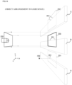
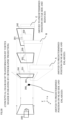
- FIG. 6 illustrates transformation performed by a vertex shader in drawing the game space shown in FIG. 5 in a frame buffer (in a process of drawing).
- the layer A is moved to a predetermined position on the near side of the layer B as seen from the virtual camera 220 and is enlarged
- the layer C is moved to a predetermined position on the far side of the layer B as seen from the virtual camera 220 and is reduced
- a depth test (Z test) using a depth buffer (Z buffer) is executed, thus performing drawing.
- the area 231 shows what size the range corresponding to the area 231 in FIG. 5 has as a result of enlargement of the layer A.
- the area 232 shows what size the range corresponding to the area 232 in FIG. 5 has as a result of reduction of the layer C.
- An area 241 is an area, of the layer A, whose image is taken by the virtual camera 220, and an area 242 is an area, of the layer C, whose image is taken by the virtual camera 220.
- a layer on a nearer side appears to be side-scrolled faster.
- a layer on a nearer side is side-scrolled faster.
- the positions of the layers A to C are adjusted by the vertex shader, and in the game image (see FIG. 4 ), the layers A to C are side-scrolled so that the layer on the nearer side appears to be side-scrolled faster.
- drawing is performed with the vertex positions transformed to such positions where the layer on the near side is further moved in the direction opposite to the movement direction of the virtual camera, and the layer on the far side is further moved along the movement direction of the virtual camera.
- drawing is performed such that, by the vertex shader, the layer (layer A) to be displayed as an object on the near side is moved to a predetermined position on the near side and is enlarged, and the layer (layer C) to be displayed as an object on the far side is moved to a predetermined position on the far side and is reduced.
- the game image with a sense of depth sufficiently expressed can be displayed.
- physics calculation processing for collision detection and the like is performed in the game space (see FIG. 5 ), and as described above, the transformation (enlargement, reduction, movement) described with reference to FIG. 6 is performed by the vertex shader, in drawing the game space. That is, in the exemplary embodiment, enlargement, reduction, or the like of an object is not performed in the game space.
- physics calculation processing for collision detection and the like might be influenced, so that verification cost is required.
- with processing in the game space kept as it is only positions and sizes in performing drawing are changed. Thus, it is possible to display the game image with a sense of depth sufficiently expressed as shown in FIG. 4 , without adjusting (correcting) the physics calculation processing.
- the layer (layer A) to be displayed as an object on the near side is moved to a predetermined position on the near side
- the layer (layer C) to be displayed as an object on the far side is moved to a predetermined position on the far side.
- FIG. 7 shows an example of a game screen in this game.
- the player character 200 which is displayed in the layer A on the game screen in FIG. 4 is displayed in the layer C. That is, in the case of FIG. 7 , the player character 200 is located in the layer C instead of the layer A in FIG. 5 and FIG. 6 .
- the player character 200 may be located in the layer B.
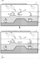
- FIG. 8 illustrates an example in which the player character 200 moves from the layer B to the layer A on the game screen in this game.
- the player character 200 displayed in the layer B goes into the entrance/exit 203 (this is an example of a case where a "second condition" is satisfied) in accordance with a player's operation, as shown in FIG. 8(2) , the player character 200 comes out from the entrance/exit 205 and thus is displayed in the layer A.
- the player character 200 displayed in the layer A goes into the entrance/exit 205 in accordance with a player's operation
- the player character 200 comes out from the entrance/exit 203 and thus is displayed in the layer B (not shown). In this way, the player character 200 can move between the layer A and the layer B.
- FIG. 9 illustrates a case where the player character 200 moves from the layer B to the layer C on the game screen in this game.
- the player character 200 displayed in the layer B goes into the entrance/exit 203 (this is an example of a case where a "second condition" is satisfied") in accordance with a player's operation, as shown in FIG. 9(2) , the player character 200 comes out from the entrance/exit 204 and thus is displayed in the layer C.
- the player character 200 displayed in the layer C goes into the entrance/exit 204 in accordance with a player's operation
- the player character 200 comes out from the entrance/exit 203 and thus is displayed in the layer B (not shown). In this way, the player character 200 can move between the layer B and the layer C.
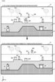
- FIG. 10 illustrates another example in which the player character 200 moves from the layer B to the layer A on the game screen in this game.
- the layer A is not displayed on the game screen. That is, the layer A is hidden on the game screen.
- FIG. 11 illustrates a game space whose image is taken for drawing the game screen (game image) shown in FIG. 10(1) .
- the virtual camera 220 and the objects are placed as in FIG. 5 .
- the player character 200 is located in the layer B.
- FIG. 12 illustrates transformation performed by the vertex shader in drawing the game space shown in FIG. 11 (in a process of drawing).
- the layer C is moved to a predetermined position on the far side of the layer B as seen from the virtual camera 220 and is reduced (without executing processing of moving and enlarging the layer A (see FIG. 6 )), and then a depth test using the depth buffer is executed, thus performing drawing.
- the game screen is displayed with the layer A not displayed.
- FIG. 13 illustrates a game space whose image is taken for drawing the game screen (game image) shown in FIG. 10(2) .
- the virtual camera 220 and the objects are placed as in FIG. 5 .
- the position of the player character 200 in the layer A is different from that in FIG. 5 .
- FIG. 14 illustrates transformation performed by the vertex shader in drawing the game space shown in FIG. 13 (in a process of drawing). As shown in FIG. 14 , in the drawing processing for the game space shown in FIG.
- the layer A is moved to a predetermined position on the near side of the layer B as seen from the virtual camera 220 and is enlarged, the layer C is moved to a predetermined position on the far side of the layer B as seen from the virtual camera 220 and is reduced, and then a depth test using the depth buffer is executed, thus performing drawing. That is, drawing is performed in the same manner as in FIG. 6 .
- FIG. 10(2) the game screen is displayed with the layer A appearing.
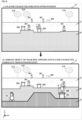
- drawing processing may be performed so that the layer A appears as raising upward.
- FIG. 15 illustrates an example in which the player character 200 moves to the hidden layer C from the layer B on the game screen in this game.
- the game screen is displayed such that, when the player character 200 goes into the entrance/exit 202 in the layer B (this is an example of a case where the "first condition" is satisfied) in accordance with a player's operation, as shown in FIG. 15(2) , the layer C appears and then the player character 200 comes out from the entrance/exit 204 in the layer C.
- the layer A is moved to a predetermined position on the near side of the layer B as seen from the virtual camera 220 and is enlarged (without executing processing of moving and reducing the layer C (see FIG. 6 )), and then a depth test using the depth buffer is executed, thus performing drawing.
- FIG. 16 illustrates a case of imparting a bloom effect (an effect as if illuminating with light) to a game image in this game.
- the layer A is colored in black.
- the bloom effect may be imparted, with a mask set on the basis of a depth (Z value, depth value) in the depth buffer for this game image.
- a depth Z value, depth value
- the bloom effect is imparted, with a bloom mask set on pixels in the layer A (an example of a "first range") having a small depth in the depth buffer.
- pixels in the layer B and the layer C an example of a "second range” and pixels in an area near the boundary of the layer A where the bloom mask is set (near the boundary with the layer B in FIG.
- pixels in the layer B and the layer C are displayed brightly as if illuminated with light, so that a sense of depth is expressed.
- pixels in the area near the boundary of the layer A where the bloom mask is set are imparted with a color (a color is added) as the pixels in the layer B and the like brightly illuminated with light are blurred.
- the color (color intensity) to be added is corrected to undergo exponentiation (or multiplication), and then the corrected color is added.
- pixels in the area near the boundary of the layer A where the bloom mask is set has a color (color intensity) weakened as compared to a case of not performing such correction, so that attenuation of the color (color intensity) is extremely sharpened.
- the depth value for setting a mask may be any value, and may be such a value that the layer B is also targeted for a mask. In addition, it can be assumed that the depths of objects in a layer are not the same. In such a case, the depth value for setting a mask may be such a value that some objects in a layer are mask targets and the others are not mask targets.
- a depth whose value is increased by the vertex shader is stored in the depth buffer and therefore can become a target of bloom, so that different expressions can be performed between the far side and the near side, whereby an expression with a more increased sense of perspective can be provided.
- FIG. 16(2) shows an image of an area near the boundary of the layer A in a case of performing the above correction
- FIG. 16(3) shows an image of an area near the boundary of the layer A in a case of not performing the above correction.
- the above correction is not shown on the enemy characters 201 and the entrance/exits 205 in the layer A (and in addition, the player character 200 in a case where the player character 200 is present in the layer A), but the above correction is performed also for these objects.
- FIG. 17 shows an example of data stored in the DRAM 85 of the game system 1.
- the DRAM 85 has at least a program storage area 301 and a data storage area 302.
- a game program 401 is stored in the program storage area 301.
- the game control data 402 includes object data 403.
- the game program 401 is a game program for executing this game processing.
- the object data 403 is data of objects to be placed in a virtual space and is data of objects such as a player character, enemy characters, items, grounds (terrains), blocks, rocks, stones, trees, and constructions.
- the object data 403 includes data of the coordinates (positions), directions, postures, states, and the like of objects.
- the image data 408 is image data of backgrounds, virtual effects, and the like.
- the virtual camera control data 409 is data for controlling movement of a virtual camera placed in a virtual space. Specifically, the virtual camera control data 409 is data for specifying the position, the orientation, the angle of view, the shooting direction, and the like of the virtual camera.
- the operation data 410 is data indicating the contents of operations performed on the left controller 3 and the right controller 4.
- the operation data 410 includes data indicating input states such as movements and orientation changes of the left controller 3 and the right controller 4 and the press states of the buttons.
- the contents of the operation data are updated at a predetermined cycle on the basis of signals from the left controller 3 and the right controller 4.
- the transmission data 411 is data to be transmitted to another game system 1, and includes at least information for identifying a transmission source and the contents of the operation data 410.
- the transmission data 411 includes data (data indicating the coordinates (position), the posture, the state, etc.) about the own player character, and the like, to be transmitted to another game system 1 of another multi-play player (or server).
- the received data 412 is data that is the transmission data received from another game system 1 and is stored in an identifiable manner for each of other game systems 1 (i.e., for each transmission source).
- the received data 412 includes data (data indicating the coordinates (position), the posture, the state, etc.) about another player character, received from another game system 1 of another multi-play player (or server).
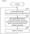
- FIG. 18 shows an example of a flowchart showing game processing and drawing processing according to the exemplary embodiment.
- processing characteristic to the exemplary embodiment will be mainly described, and description for other matters is omitted.
- step S100 the processor 81 (CPU function of processor 81) performs game processing in a game space. Specifically, the processor 81 performs physics calculation processing in the game space, action processing for the enemy characters 201, action processing for the player character 200 based on the operation data 410, and the like. Then, the process proceeds to step S200.
- step S200 the processor 81 (GPU function of processor 81) performs drawing processing of drawing the game space by orthographic projection, to generate a game image. Specifically, as described with reference to FIG. 4 to FIG. 7 , etc., by the vertex shader, the processor 81 moves the layer (layer A) to be displayed as an object on the near side, to a predetermined position on the near side, and enlarges the layer, and moves the layer (layer C) to be displayed as an object on the far side, to a predetermined position on the far side, and reduces the layer, thus performing drawing in the frame buffer.
- the processor 81 moves the layer (layer A) to be displayed as an object on the near side, to a predetermined position on the near side, and enlarges the layer, and moves the layer (layer C) to be displayed as an object on the far side, to a predetermined position on the far side, and reduces the layer, thus performing drawing in the frame buffer.
- the player character 200 moves to a hidden layer on the basis of a
- the processor 81 performs drawing processing of causing the hidden layer to appear on the game screen (game image).
- the processor 81 performs processing of imparting a bloom effect to the game image drawn in the frame buffer through transformation processing by the vertex shader, on the basis of the depth in the depth buffer for this game image.
- the processor 81 sets a bloom mask for a predetermined layer and performs predetermined correction regarding the bloom effect, for pixels in an area near the boundary of the predetermined layer. Then, the process proceeds to step S300.
- step S300 the display 12 displays the game image generated in step S200. Then, the process returns to step S 100.
- a layer to be displayed as an object on the near side is moved to a predetermined position on the near side and is enlarged, and a layer to be displayed as an object on the far side is moved to a predetermined position on the far side and is reduced, thus performing drawing in the frame buffer (see FIG. 4 to FIG. 7 , etc.).
- the game image drawn (taken) by orthographic projection can be expressed with a sufficient sense of depth.
- a bloom mask is set for a predetermined layer, and predetermined correction regarding the bloom effect is performed on pixels in an area near the boundary of the predetermined layer (see FIG. 16 ).
- a light emission effect that sufficiently exhibits a sense of depth can be provided to the game image drawn (taken) by orthographic projection.
- the example in which the objects (terrain object, player character, enemy character, etc.) displayed in the same layer on the game screen are placed in the same layer also in the game space and the like, has been shown (see FIG. 4 to FIG. 7 , etc.).
- the objects (terrain object, player character, enemy character, etc.) included in the layer A displayed in the game image in FIG. 4 are placed in the layer A also in the game space shown in FIG. 5 and in transformation in drawing processing shown in FIG. 6 .
- an object displayed so as to be present on a terrain on the game screen may be placed in a layer different from the layer of the terrain.
- the player character 200 displayed so as to be present on the terrain object A on the game screen is placed on the virtual camera 220 side (near side) relative to the terrain object A, in the game space.
- physics calculation processing such as collision detection processing
- setting processing
- the physics calculation processing is set so that the player character 200 will not fall because the terrain object A is not present under the player character 200.
- transformation in drawing processing as shown in FIG. 20
- both of the player character 200 and the layer A are moved to predetermined positions on the near side and are enlarged, to perform drawing in the frame buffer, whereby the same game image as in FIG. 4 can be generated.
- the example in which three layers (layers A to C) are placed in the game space has been shown (see FIG. 4 to FIG. 6 , etc.).
- the number of layers placed in the game space is not limited thereto.
- movement and the like are performed for layers other than the layer B, using the layer B as a reference layer for which movement and the like are not performed, to generate a game image (see FIG. 5 , FIG. 6 , etc.).
- movement and the like may be performed for layers other than the layer A, using the layer A as a reference layer for which movement and the like are not performed, to generate a game image.
- such transformation that the layer B and the layer C are moved to the far side of the layer A and are reduced, is performed by the vertex shader.
- movement and the like may be performed for layers other than the layer C, using the layer C as a reference layer for which movement and the like are not performed, to generate a game image.
- such transformation that the layer A and the layer B are moved to the near side of the layer C and are enlarged, is performed by the vertex shader.
- the positions where the layers A to C are placed in the game space may be any positions as long as the positions of the layers transformed by the vertex shader (see FIG. 6 ) are not changed in the drawing processing.
- the layer C may be placed at a position on the near side of the layer B (position on the virtual camera 220 side), and the drawing processing may be performed so that the position of the layer C transformed by the vertex shader becomes the position shown in FIG. 6 (position on the far side of the layer B), to draw a game image.
- the sequential processing in the game processing is executed by a single game apparatus.
- the sequential processing may be executed in an information processing system including a plurality of information processing apparatuses.
- a part of the sequential processing may be executed by the server-side apparatus.
- a major part of the sequential processing may be executed by the server-side apparatus and a part of the sequential processing may be executed by the terminal-side apparatus.
- a server-side system may include a plurality of information processing apparatuses and processing to be executed on the server side may be executed by the plurality of information processing apparatuses in a shared manner.
- a configuration of so-called cloud gaming may be adopted.
- the game apparatus may transmit operation data indicating a user's operation to a predetermined server, various game processing may be executed on the server, and the execution result may be distributed as a video and a sound by streaming to the game apparatus.
Landscapes
- Engineering & Computer Science (AREA)
- Multimedia (AREA)
- Theoretical Computer Science (AREA)
- Human Computer Interaction (AREA)
- Processing Or Creating Images (AREA)
- Image Generation (AREA)
- User Interface Of Digital Computer (AREA)
Applications Claiming Priority (1)
| Application Number | Priority Date | Filing Date | Title |
|---|---|---|---|
| JP2023149370A JP7614280B2 (ja) | 2023-09-14 | 2023-09-14 | ゲームプログラム、ゲームシステム、ゲーム装置、およびゲーム処理方法 |
Publications (1)
| Publication Number | Publication Date |
|---|---|
| EP4523767A1 true EP4523767A1 (de) | 2025-03-19 |
Family
ID=89129629
Family Applications (1)
| Application Number | Title | Priority Date | Filing Date |
|---|---|---|---|
| EP24153725.7A Pending EP4523767A1 (de) | 2023-09-14 | 2024-01-24 | Spielprogramm, spielverarbeitungssystem, spielverarbeitungsgerät und spielverarbeitungsverfahren |
Country Status (3)
| Country | Link |
|---|---|
| US (1) | US20250090955A1 (de) |
| EP (1) | EP4523767A1 (de) |
| JP (2) | JP7614280B2 (de) |
Families Citing this family (1)
| Publication number | Priority date | Publication date | Assignee | Title |
|---|---|---|---|---|
| JP7491977B2 (ja) * | 2022-10-26 | 2024-05-28 | 任天堂株式会社 | ゲームプログラム、ゲームシステム、ゲーム装置、およびゲーム処理方法 |
Citations (1)
| Publication number | Priority date | Publication date | Assignee | Title |
|---|---|---|---|---|
| JP2020154923A (ja) * | 2019-03-22 | 2020-09-24 | 任天堂株式会社 | 画像処理プログラム、画像処理システム、画像処理装置、および画像処理方法 |
Family Cites Families (11)
| Publication number | Priority date | Publication date | Assignee | Title |
|---|---|---|---|---|
| JP2002200330A (ja) * | 2000-09-22 | 2002-07-16 | Sega Corp | 遊戯装置及びその運営システム |
| JP4734138B2 (ja) * | 2006-02-23 | 2011-07-27 | 株式会社バンダイナムコゲームス | プログラム、情報記憶媒体及び画像生成システム |
| JP2010033297A (ja) * | 2008-07-28 | 2010-02-12 | Namco Bandai Games Inc | プログラム、情報記憶媒体、及び画像生成システム |
| JP2011101752A (ja) * | 2009-11-11 | 2011-05-26 | Namco Bandai Games Inc | プログラム、情報記憶媒体、及び、画像生成装置 |
| JP2013171539A (ja) * | 2012-02-22 | 2013-09-02 | Sharp Corp | 映像処理装置、映像処理方法及びコンピュータプログラム |
| JP6487578B1 (ja) * | 2018-01-05 | 2019-03-20 | 株式会社スクウェア・エニックス | プログラム、記録媒体、及び影描画方法 |
| JP6993585B2 (ja) * | 2019-05-24 | 2022-01-13 | 株式会社カプコン | ゲームプログラム及びゲーム装置 |
| JP7293036B2 (ja) * | 2019-08-09 | 2023-06-19 | 任天堂株式会社 | 情報処理装置、情報処理プログラム、情報処理システム及び情報処理方法 |
| JP2021111129A (ja) * | 2020-01-10 | 2021-08-02 | 凸版印刷株式会社 | 画像処理装置、画像処理方法、及びプログラム |
| JP7812633B2 (ja) * | 2021-09-30 | 2026-02-10 | 株式会社Cygames | プログラム、情報処理装置および情報処理方法 |
| JP7506102B2 (ja) * | 2022-01-04 | 2024-06-25 | 株式会社Cygames | プログラム、情報処理装置および情報処理方法 |
-
2023
- 2023-09-14 JP JP2023149370A patent/JP7614280B2/ja active Active
-
2024
- 2024-01-22 US US18/418,602 patent/US20250090955A1/en active Pending
- 2024-01-24 EP EP24153725.7A patent/EP4523767A1/de active Pending
- 2024-12-26 JP JP2024230849A patent/JP2025042635A/ja active Pending
Patent Citations (1)
| Publication number | Priority date | Publication date | Assignee | Title |
|---|---|---|---|---|
| JP2020154923A (ja) * | 2019-03-22 | 2020-09-24 | 任天堂株式会社 | 画像処理プログラム、画像処理システム、画像処理装置、および画像処理方法 |
Also Published As
| Publication number | Publication date |
|---|---|
| JP2023178520A (ja) | 2023-12-15 |
| JP2025042635A (ja) | 2025-03-27 |
| JP7614280B2 (ja) | 2025-01-15 |
| US20250090955A1 (en) | 2025-03-20 |
Similar Documents
| Publication | Publication Date | Title |
|---|---|---|
| US10409365B2 (en) | Method of providing a virtual space image subjected to blurring processing based on detected displacement, and system therefor | |
| US8882593B2 (en) | Game processing system, game processing method, game processing apparatus, and computer-readable storage medium having game processing program stored therein | |
| US9904982B2 (en) | System and methods for displaying panoramic content | |
| US9433860B2 (en) | Game system, game processing method, computer-readable storage medium having stored therein game program, and game apparatus | |
| US12478874B2 (en) | Computer-readable non-transitory storage medium having game program stored therein, game apparatus, game system, and game processing method | |
| US8662976B2 (en) | Game processing system, game processing method, game processing apparatus, and computer-readable storage medium having game processing program stored therein | |
| US20250032913A1 (en) | Non-transitory computer-readable storage medium having game program stored therein, game processing system, game processing apparatus, and game processing method | |
| US9256979B2 (en) | Storage medium having stored thereon image display program, image display system, image display method, and image display apparatus | |
| US20190060755A1 (en) | Game system, non-transitory storage medium having game program stored therein, game apparatus, and game processing method | |
| US12551798B2 (en) | Storage medium, information processing system, information processing apparatus, and game processing method | |
| JP2024538553A (ja) | 仮想オブジェクトの切替方法、装置、コンピュータデバイス及びコンピュータプログラム | |
| EP1808210B1 (de) | Aufzeichnungsmedium für Spielprogramm und Spielvorrichtung | |
| JP2014097219A (ja) | ゲームプログラム、ゲーム装置、ゲームシステム、およびゲーム処理方法 | |
| US20250090955A1 (en) | Computer-readable non-transitory storage medium having game program stored therein, game processing system, game processing apparatus, and game processing method | |
| US12496520B2 (en) | Computer-readable non-transitory storage medium, information processing apparatus, information processing system, and information processing method | |
| US20130109475A1 (en) | Game system, control method therefor, and a storage medium storing a computer program | |
| US11285394B1 (en) | Computer-readable non-transitory storage medium having instructions stored therein, game apparatus, game system, and game processing method | |
| US20240416233A1 (en) | Computer-readable non-transitory storage medium having game program stored therein, game processing system, and game processing method | |
| US12616898B2 (en) | Computer-readable non-transitory storage medium having game program stored therein, game processing system, and game processing method | |
| US20050068313A1 (en) | Game software and game machine | |
| US20250245907A1 (en) | Non-transitory computer-readable medium, image processing system, image processing method, and image processing apparatus | |
| US12390736B2 (en) | Non-transitory computer-readable storage medium having game program stored therein, game processing system, game processing apparatus, and game processing method | |
| US12420196B2 (en) | Computer-readable non-transitory storage medium having information processing program for storing footprint coordinate sets in order of time series | |
| US20240139628A1 (en) | Storage medium, game system, game apparatus, and game processing method | |
| US20130109451A1 (en) | Game system, control method therefor, and a storage medium storing a computer program |
Legal Events
| Date | Code | Title | Description |
|---|---|---|---|
| PUAI | Public reference made under article 153(3) epc to a published international application that has entered the european phase |
Free format text: ORIGINAL CODE: 0009012 |
|
| STAA | Information on the status of an ep patent application or granted ep patent |
Free format text: STATUS: REQUEST FOR EXAMINATION WAS MADE |
|
| 17P | Request for examination filed |
Effective date: 20250212 |
|
| AK | Designated contracting states |
Kind code of ref document: A1 Designated state(s): AL AT BE BG CH CY CZ DE DK EE ES FI FR GB GR HR HU IE IS IT LI LT LU LV MC ME MK MT NL NO PL PT RO RS SE SI SK SM TR |
|
| STAA | Information on the status of an ep patent application or granted ep patent |
Free format text: STATUS: EXAMINATION IS IN PROGRESS |
|
| 17Q | First examination report despatched |
Effective date: 20260102 |