EP4521177A1 - Vorrichtung zum fügen und fügeverfahren mit einer erfassungseinrichtung zum ausrichten eines fügekopfes - Google Patents
Vorrichtung zum fügen und fügeverfahren mit einer erfassungseinrichtung zum ausrichten eines fügekopfes Download PDFInfo
- Publication number
- EP4521177A1 EP4521177A1 EP23196211.9A EP23196211A EP4521177A1 EP 4521177 A1 EP4521177 A1 EP 4521177A1 EP 23196211 A EP23196211 A EP 23196211A EP 4521177 A1 EP4521177 A1 EP 4521177A1
- Authority
- EP
- European Patent Office
- Prior art keywords
- joining
- workpiece
- axis
- detection device
- orientation
- Prior art date
- Legal status (The legal status is an assumption and is not a legal conclusion. Google has not performed a legal analysis and makes no representation as to the accuracy of the status listed.)
- Pending
Links
Images

Classifications
-
- G—PHYSICS
- G05—CONTROLLING; REGULATING
- G05B—CONTROL OR REGULATING SYSTEMS IN GENERAL; FUNCTIONAL ELEMENTS OF SUCH SYSTEMS; MONITORING OR TESTING ARRANGEMENTS FOR SUCH SYSTEMS OR ELEMENTS
- G05B19/00—Program-control systems
- G05B19/02—Program-control systems electric
- G05B19/18—Numerical control [NC], i.e. automatically operating machines, in particular machine tools, e.g. in a manufacturing environment, so as to execute positioning, movement or co-ordinated operations by means of program data in numerical form
- G05B19/402—Numerical control [NC], i.e. automatically operating machines, in particular machine tools, e.g. in a manufacturing environment, so as to execute positioning, movement or co-ordinated operations by means of program data in numerical form characterised by control arrangements for positioning, e.g. centring a tool relative to a hole in the workpiece, additional detection means to correct position
-
- B—PERFORMING OPERATIONS; TRANSPORTING
- B23—MACHINE TOOLS; METAL-WORKING NOT OTHERWISE PROVIDED FOR
- B23K—SOLDERING OR UNSOLDERING; WELDING; CLADDING OR PLATING BY SOLDERING OR WELDING; CUTTING BY APPLYING HEAT LOCALLY, e.g. FLAME CUTTING; WORKING BY LASER BEAM
- B23K9/00—Arc welding or cutting
- B23K9/20—Stud welding
-
- B—PERFORMING OPERATIONS; TRANSPORTING
- B23—MACHINE TOOLS; METAL-WORKING NOT OTHERWISE PROVIDED FOR
- B23K—SOLDERING OR UNSOLDERING; WELDING; CLADDING OR PLATING BY SOLDERING OR WELDING; CUTTING BY APPLYING HEAT LOCALLY, e.g. FLAME CUTTING; WORKING BY LASER BEAM
- B23K9/00—Arc welding or cutting
- B23K9/20—Stud welding
- B23K9/201—Stud welding of the extremity of a small piece on a large basis
-
- B—PERFORMING OPERATIONS; TRANSPORTING
- B23—MACHINE TOOLS; METAL-WORKING NOT OTHERWISE PROVIDED FOR
- B23K—SOLDERING OR UNSOLDERING; WELDING; CLADDING OR PLATING BY SOLDERING OR WELDING; CUTTING BY APPLYING HEAT LOCALLY, e.g. FLAME CUTTING; WORKING BY LASER BEAM
- B23K9/00—Arc welding or cutting
- B23K9/20—Stud welding
- B23K9/201—Stud welding of the extremity of a small piece on a large basis
- B23K9/202—Stud welding of the extremity of a small piece on a large basis by means of portable equipment, e.g. stud-welding gun
-
- B—PERFORMING OPERATIONS; TRANSPORTING
- B23—MACHINE TOOLS; METAL-WORKING NOT OTHERWISE PROVIDED FOR
- B23K—SOLDERING OR UNSOLDERING; WELDING; CLADDING OR PLATING BY SOLDERING OR WELDING; CUTTING BY APPLYING HEAT LOCALLY, e.g. FLAME CUTTING; WORKING BY LASER BEAM
- B23K9/00—Arc welding or cutting
- B23K9/20—Stud welding
- B23K9/206—Stud welding with automatic stud supply
-
- G—PHYSICS
- G05—CONTROLLING; REGULATING
- G05B—CONTROL OR REGULATING SYSTEMS IN GENERAL; FUNCTIONAL ELEMENTS OF SUCH SYSTEMS; MONITORING OR TESTING ARRANGEMENTS FOR SUCH SYSTEMS OR ELEMENTS
- G05B19/00—Program-control systems
- G05B19/02—Program-control systems electric
- G05B19/42—Recording and playback systems, i.e. in which the program is recorded from a cycle of operations, e.g. the cycle of operations being manually controlled, after which this record is played back on the same machine
-
- G—PHYSICS
- G05—CONTROLLING; REGULATING
- G05B—CONTROL OR REGULATING SYSTEMS IN GENERAL; FUNCTIONAL ELEMENTS OF SUCH SYSTEMS; MONITORING OR TESTING ARRANGEMENTS FOR SUCH SYSTEMS OR ELEMENTS
- G05B2219/00—Program-control systems
- G05B2219/30—Nc systems
- G05B2219/45—Nc applications
- G05B2219/45135—Welding
Definitions
- the present invention relates to a device and a method for aligning a joining head which is used to carry out a joining process on a workpiece. More particularly, the present invention may be implemented in the field of stud welding or drawn arc welding or drawn arc ignition welding. However, the device and the method can be implemented also in other processes such as riveting, adhesive bonding, blind fastening, plasma pinning or the like adapted to set a joining element on or in a workpiece arrangement.
- a joining element In drawn arc welding, a joining element is held using a welding tool with a welding head and placed on a workpiece. By forming a circuit, a current flows between the welding head and the workpiece through the joining element. To ignite an arc, the joining element is lifted slightly from the workpiece using the welding tool. The resulting arc melts the workpiece and/or the joining element. To end the process, the joining element is lowered onto the workpiece and pressed into the melt. The electricity is switched off and the melt cools.
- Misalignments can mean that the joining processes subsequently carried out with the robot only lead to a lower quality of the joint.
- DE102011010438A1 from the applicant is based on the idea of fixing an alignment device on a joining tool instead of manually aligning a joining tool and placing a support surface of the alignment device on a surface of a workpiece, whereby the alignment device can be used to check whether the joining tool is correctly aligned in relation to the surface of the workpiece.
- JPH05376A discloses a stud welding apparatus used for welding a stud component to a workpiece comprising a correction device having a pair of laser sensors attached to both sides of ta stud gun. A laser beam is emitted from the laser sensors so that the distance to the object that the laser beam strikes can be measured, and the measurement result is fed back to the control circuit. By feeding back to a control circuit, the amount of rotation of servo motors can be corrected and controlled in accordance with the feedback signal.
- US2013015163A1 is directed to a stud welding gun comprising devices for detecting, displaying and controlling the orientation of the stud welding gun.
- DE102018208872 discloses a method for drawn ignition welding, in which a welding part is welded onto a component surface using a welding tool. The welding part is moved along a joining axis of the welding tool relative to the component, and before the start of welding, the alignment of the joining axis of the welding tool relative to the component surface is determined by means of a detection device. Then, the welding tool is positioned such that the joining axis is aligned perpendicular to the component surface.
- the fixation of a further device on the joining tool to determine the alignment of the tool implies an increase in weight and space requirement of the joining tool. Besides, misalignment may still occur depending on the accuracy of the alignment device and its arrangement on the device. It is therefore an object of the present invention to provide a joining device comprising a position detection unit adapted to provide continuous and accurate values without increasing the space requirement of the joining device and with an automatic position correction to ensure that the joining axis of the joining device is always correct with regard to the workpiece surface. It is also an object of the present disclosure to provide a joining method providing an automated fine adjustment of the joining axis by means of a teach-in (or learning) process.
- the present invention provides a joining device according to claim 1 and a joining method according to claim 9. More particularly, the device for joining, in particular arc welding, a joining element, preferably a stud, to a workpiece comprises a joining head having:
- Such joining device with an orientation detection device is adapted for continuously ensuring the correct position or orientation of the joining head with regard to the workpiece surface.
- the system detects the position of the joining head and the joining axis relative to the workpiece surface and corrects said position or orientation if necessary, before the welding process actually begins. Welding errors are thus avoided.
- the integration of the detection device within the supporting device and therefore in the vicinity of the joining point on the workpiece increases the accuracy of the detection without increasing the space requirements. No manual intervention of an operator is necessary and the joining axis orientation is automatically corrected in case of deviation.
- the supporting device comprises a main body having an opening adapted to receive the joining element and a supporting surface adapted to face the workpiece, and wherein the detection device is arranged on or in the vicinity of the supporting surface.
- the detection device forms at least in part the supporting surface.
- the detection device comprises a sensor mounting ring movably mounted on the main body, the sensor mounting ring comprising a surface adapted to contact the workpiece.
- the detection device is thus adapted to be in direct contact with the workpiece surface and does not protrude from the joining device.
- the detection device comprises a compression ring arranged between the sensor mounting ring and the main body.
- the compression ring allows tolerance adjustment.
- the sensor mounting ring is connected to the mouthpiece through an anti-rotation device.
- the sensor mounting ring is not rotatably movable around the joining axis.
- a spacer cooperating with a groove can be used to connect the sensor mounting ring to the mouthpiece.
- the detection device comprises MEMs sensors for position measurement and the control device interacts with the MEMs sensors for calculating the orientation of the joining axis.
- MEMS sensors are small in size and possess extremely high sensitivity. Thus, the mouthpiece remains compact, and the detection device is accurate.
- the MEMs sensors are fixed to the sensor mounting ring.
- the MEMs sensors measurement of the joining axis orientation with regard to the workpiece surface is accurate.
- the present invention is also directed to a joining method, in particular a method for drawn arc ignition welding, in which a joining element, preferably a stud, is joined on a workpiece surface using a device comprising the steps of:
- the joining method allows an exact alignment of the joining axis in relation to the workpiece.
- the teach-in (or computer implemented learning) processes can be simplified and accelerated, since the operator no longer has to adjust manually the joining axis position and orientation.
- control device records the orientation values of the joining head before the joining step and automatically corrects the orientation of the joining head during the joining step.
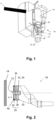
- Fig. 1 shows a joining device 10 adapted for joining a fastener or joining element 12 to a workpiece 14.
- the joining element 12 is for instance a stud with a shaft and an enlarged flange, the flange being destined to be fastened to the workpiece 14.
- the joining device 10, as shown in Fig. 1 is more particularly an arc stud welding device.
- the joining element may be a rivet, a blind fastener, a glue stud, a pin or the like.
- the joining device is a riveting device, a blind fastener setting device, an adhesive bonding device, a plasma joining device and the like.
- the joining device 10 in a well-known manner comprises a retaining device 16 adapted to retain the joining element 12 which is intended to be connected to the workpiece 14.
- the joining element 12 is moved along a joining axis of the joining device 10 relative to the workpiece.
- the joining element 12 first is placed on a joining surface of a workpiece (also called workpiece surface). Subsequently, a reduced electric current in the form of a pilot current is switched on. After that, the joining element 12 is raised from the workpiece surface so that an arc is drawn. Then, the electric current is increased to a welding current which may be greater than 1000 ampere. The mutually opposed faces of the joining element 12 and the workpiece thereby melt. Subsequently, the joining element 12 is lowered onto the workpiece 14, preferably as far as a location below the workpiece surface so that the electric current is short-circuited and switched off.
- the overall melt hardens so that a materially engaging connection is achieved between the joining element 12 and the workpiece 14.
- the retaining device 16 can be axially moved along a longitudinal axis A which forms the joining axis, in order to axially raise and lower the joining element 12 along a joining axis with respect to the workpiece 14.
- the stud welding process will not be further described here, as those skilled in the art understand and appreciate how stud welding process and arc stud welding devices operate.
- the joining device 10 comprises a joining head with supporting device 18 adapted to contact against the workpiece.
- the supporting device comprises a main body 20 and a supporting surface adapted to contact the surface of a workpiece.
- the main body has an opening adapted to receive the joining element.
- the supporting surface id adapted to face and contact the workpiece.
- the supporting device 18, during the joining process is in the vicinity of the joining area wherein the joining element is fixed.
- the supporting device is thus arranged at a front end of the joining head and in such a manner that the retaining device 16 can carry out relative movements with regard to the workpiece 14.
- the supporting device 18 is fixed to a housing 19 of the joining device 10.
- the supporting device 18 has a base member or main body 20 partially defining the axial opening 22 extending along the longitudinal axis A.
- the retaining device 16 with a joining element 12 can be received inside the opening 22.
- the supporting device is a protective gas mouthpiece 18 adapted to contact against the workpiece to enclose the joining element within a sealed chamber containing protective joining gas during the joining process.
- the opening 22 defines a cleaning space 26 in which the protective gas can be introduced and which, when the joining process is carried out, is axially delimited by the workpiece which covers the opening 22.
- Protective gas can be supplied to the cleaning space 26 to displace ambient gas, such as air, from the cleaning space 26 in order to improve the above-described stud welding process.
- the supporting device may also be a structure attached at the front end of the joining head and adapted to be moved in the vicinity of the joint for improving the joining process or at least without negatively interfering with the joining process.
- a mouthpiece may not be necessary, contrary to aluminium welding processes.
- the longitudinal axis A is often aligned with the joining axis of the joining element 12.
- the joining device 10 further comprises a detection device 28 for determining the relative orientation of the joining axis X with regard to the workpiece surface.
- the detection device 28, as better seen in Fig. 2 is arranged on the supporting device 18 , which could be a mouthpiece 18. More particularly, the detection device 28 forms a mouth of the supporting device adapted to contact the workpiece18.
- the detection device 28 is arranged around the opening 22.
- the detection device 28 comprises a sensor mounting ring 30 movably mounted on the supporting device 18. More particularly the sensor mounting ring 30 is connected to the base member 20 of the supporting device through an anti-rotation device 32.
- the anti-rotation device 32 comprises a spacer 34 which is arranged in a groove 36 formed in the base member 20 and the sensor mounting ring 30.
- the spacer 34 is fixedly connected to the base member 20 and can translate within the portion of the groove formed in the sensor mounting ring 30.
- a compression ring 38 may be arranged between the sensor mounting ring 30 and the base member 20.
- the compression ring 38 also comprises a groove which is in the continuity of the groove formed in the sensor mounting ring 30 and base member 20.
- MEMS sensors 40 are arranged on the sensor mounting ring 30 in order to detect and measure the position and movements of the sensor mounting ring.
- the MEMs sensors are for instance fixed to the outer lateral part of the sensor mounting ring 30.
- the MEMs sensors 40 interact directly with a control device 42 fixed on the housing 19 of the joining head.
- the control device 42 stores and processes the values sent by the MEMs sensors 40 in order to determine the exact orientation of the joining axis X with regard to the workpiece, as described below. Once the exact orientation of the joining axis X with regard to the workpiece is detected, it can be corrected so that the joining axis X is aligned perpendicular to the workpiece surface.
- the control device 42 interacts directly with a robot arm 44 supporting the joining head or a displacement unit controlling the position of the joining head such that the position of the joining head is automatically corrected such that the joining axis X remains orthogonal to the workpiece surface.
- the joining method with the alignment function works as follows.
- the joining head of the joining device 10 is directed toward the workpiece 14 until the detection device 28 contacts the workpiece 14. More particularly, the joining head is directed toward the workpiece surface until the sensor mounting ring contacts the workpiece. If the joining axis X is already orthogonal to the workpiece surface, then the sensor mounting ring 30 contacts the workpiece and the compression on the compression ring is similar in all point of the compression ring. If there is a misalignment between the joining axis X and the normal to the workpiece surface, the compression on the compression ring will not be regular and an angle will appear.
- the MEMs sensor can record the difference or angle.
- the values recorded by the MEMs sensors 40 are sent to the control device 42 which can detect a misalignment between the joining axis X and the normal to the workpiece surface and correct it in real-time such that the orientation of the joining head is automatically corrected. For instance, a robot slightly rotates the joining head such that the joining axis is orthogonal to the workpiece. Once the correction has been done, the correct positioning values of the joining head are recorded for the welding process. The joining head is then automatically aligned perpendicular to the workpiece surface and the joining element 12 can be joined on the workpiece surface.
- Fig. 3 schematically shows the possible joining steps of the joining method.
- a first step (S1) the joining device 10 is moved by a robot arm to the joining position.
- the joining head is moved (for instance by a carriage) along the joining axis up to the workpiece surface such that the detection device (and more particularly the sensor mounting ring) contacts the workpiece surface.
- the detection device 28 (and more particularly the sensor mounting ring) is adjusted on the workpiece surface.
- a pilot current is switched on.
- a fifth step (S5) the values measured by the detection device (and more particularly the MEMs sensors) are interpreted such that the angle between the joining axis and the axis perpendicular to the workpiece surface is measured, for instance by the control device or a micro-controller.
- the angle correction is calculated and a robot arm corrects the position of the joining head such that the joining axis becomes perpendicular to the workpiece surface.
- the pilot current is switched off.
- the joining process is completed.
Landscapes
- Engineering & Computer Science (AREA)
- Physics & Mathematics (AREA)
- Plasma & Fusion (AREA)
- Mechanical Engineering (AREA)
- Human Computer Interaction (AREA)
- Manufacturing & Machinery (AREA)
- General Physics & Mathematics (AREA)
- Automation & Control Theory (AREA)
- Automatic Assembly (AREA)
- Butt Welding And Welding Of Specific Article (AREA)
Priority Applications (3)
| Application Number | Priority Date | Filing Date | Title |
|---|---|---|---|
| EP23196211.9A EP4521177A1 (de) | 2023-09-08 | 2023-09-08 | Vorrichtung zum fügen und fügeverfahren mit einer erfassungseinrichtung zum ausrichten eines fügekopfes |
| PCT/EP2024/074826 WO2025051855A1 (en) | 2023-09-08 | 2024-09-05 | Device for joining and joining method with a detection device for aligning a joining head |
| CN202480057295.8A CN121794632A (zh) | 2023-09-08 | 2024-09-05 | 具有可校准接合头的检测装置以用于接合的装置和接合方法 |
Applications Claiming Priority (1)
| Application Number | Priority Date | Filing Date | Title |
|---|---|---|---|
| EP23196211.9A EP4521177A1 (de) | 2023-09-08 | 2023-09-08 | Vorrichtung zum fügen und fügeverfahren mit einer erfassungseinrichtung zum ausrichten eines fügekopfes |
Publications (1)
| Publication Number | Publication Date |
|---|---|
| EP4521177A1 true EP4521177A1 (de) | 2025-03-12 |
Family
ID=88016475
Family Applications (1)
| Application Number | Title | Priority Date | Filing Date |
|---|---|---|---|
| EP23196211.9A Pending EP4521177A1 (de) | 2023-09-08 | 2023-09-08 | Vorrichtung zum fügen und fügeverfahren mit einer erfassungseinrichtung zum ausrichten eines fügekopfes |
Country Status (3)
| Country | Link |
|---|---|
| EP (1) | EP4521177A1 (de) |
| CN (1) | CN121794632A (de) |
| WO (1) | WO2025051855A1 (de) |
Citations (7)
| Publication number | Priority date | Publication date | Assignee | Title |
|---|---|---|---|---|
| US4380696A (en) * | 1980-11-12 | 1983-04-19 | Unimation, Inc. | Method and apparatus for manipulator welding apparatus with vision correction for workpiece sensing |
| US4403281A (en) * | 1981-04-03 | 1983-09-06 | Cincinnati Milacron Industries, Inc. | Apparatus for dynamically controlling the tool centerpoint of a robot arm off a predetermined path |
| US4667082A (en) * | 1984-12-27 | 1987-05-19 | Hitachi, Ltd. | Welding position detecting apparatus |
| DE102011010438A1 (de) | 2011-02-04 | 2012-08-09 | Newfrey Llc | Vorrichtung und Verfahren zum Ausrichten eines Fügewerkzeuges |
| US20130015163A1 (en) | 2011-07-15 | 2013-01-17 | Illinois Tool Works Inc. | Stud welding system, consumables, and method |
| DE102018208872A1 (de) | 2018-06-06 | 2019-12-12 | Bayerische Motoren Werke Aktiengesellschaft | Verfahren zum Hubzündungsschweißen und Hubzündungsschweißvorrichtung |
| WO2022186054A1 (ja) * | 2021-03-02 | 2022-09-09 | ファナック株式会社 | センサの出力に基づいて教示点を生成する教示点生成装置および教示点生成方法 |
-
2023
- 2023-09-08 EP EP23196211.9A patent/EP4521177A1/de active Pending
-
2024
- 2024-09-05 WO PCT/EP2024/074826 patent/WO2025051855A1/en active Pending
- 2024-09-05 CN CN202480057295.8A patent/CN121794632A/zh active Pending
Patent Citations (7)
| Publication number | Priority date | Publication date | Assignee | Title |
|---|---|---|---|---|
| US4380696A (en) * | 1980-11-12 | 1983-04-19 | Unimation, Inc. | Method and apparatus for manipulator welding apparatus with vision correction for workpiece sensing |
| US4403281A (en) * | 1981-04-03 | 1983-09-06 | Cincinnati Milacron Industries, Inc. | Apparatus for dynamically controlling the tool centerpoint of a robot arm off a predetermined path |
| US4667082A (en) * | 1984-12-27 | 1987-05-19 | Hitachi, Ltd. | Welding position detecting apparatus |
| DE102011010438A1 (de) | 2011-02-04 | 2012-08-09 | Newfrey Llc | Vorrichtung und Verfahren zum Ausrichten eines Fügewerkzeuges |
| US20130015163A1 (en) | 2011-07-15 | 2013-01-17 | Illinois Tool Works Inc. | Stud welding system, consumables, and method |
| DE102018208872A1 (de) | 2018-06-06 | 2019-12-12 | Bayerische Motoren Werke Aktiengesellschaft | Verfahren zum Hubzündungsschweißen und Hubzündungsschweißvorrichtung |
| WO2022186054A1 (ja) * | 2021-03-02 | 2022-09-09 | ファナック株式会社 | センサの出力に基づいて教示点を生成する教示点生成装置および教示点生成方法 |
Also Published As
| Publication number | Publication date |
|---|---|
| WO2025051855A1 (en) | 2025-03-13 |
| CN121794632A (zh) | 2026-04-03 |
Similar Documents
| Publication | Publication Date | Title |
|---|---|---|
| US7528344B2 (en) | Determining the relative positions of the axes of a laser machining beam and a process gas jet | |
| US7863539B2 (en) | Positioning method of spot welding robot | |
| CN103358308B (zh) | 机器人焊枪取向规范化 | |
| JPH02284885A (ja) | ワーク位置決め装置の位置教示方法 | |
| EP1123769A2 (de) | Schweissroboter | |
| CN111055046B (zh) | 示教位置校正方法 | |
| KR20190063732A (ko) | 레이저 용접 품질 유지용 복합 지그 장치 및 이를 이용한 용접 장치의 제어 방법 | |
| CN116423190B (zh) | 回转支承螺栓定位拧紧方法和可读存储介质 | |
| WO2003006199A1 (en) | Resistance welding fastener electrode | |
| CN111683782B (zh) | 摩擦搅拌接合装置以及摩擦搅拌接合方法 | |
| WO2014129162A1 (ja) | 産業用ロボットおよび産業用ロボットのツール取り付け位置の較正方法 | |
| US20150076126A1 (en) | Welding and cutting laser displacement compensation system | |
| WO2025051855A1 (en) | Device for joining and joining method with a detection device for aligning a joining head | |
| US5189514A (en) | Guidance system for automatic riveters | |
| JP2008544860A (ja) | 被加工材の溶接方法 | |
| US5489759A (en) | Method and device for aligning a tool held by a robot | |
| KR20190104362A (ko) | 아크점 조정봉 장착 구조, 다관절 용접 로봇 및 용접 장치 | |
| US6921876B2 (en) | Method for adjusting nozzle gap | |
| CN116897099B (zh) | 根据传感器的输出生成示教点的示教点生成装置以及示教点生成方法 | |
| JP2009056480A (ja) | スポット溶接ガンを用いたスポット溶接方法 | |
| KR100621223B1 (ko) | 로봇 툴과 레이저 비전 센서 간의 위치 보정 지그 | |
| US20230001502A1 (en) | Method for the Thermal Processing of a Workpiece with a Thermal Processing Machine | |
| JPH06170572A (ja) | レ−ザ加工機のギャップ量検出装置 | |
| US20220226925A1 (en) | Welding apparatus and plate thickness testing method for welding apparatus | |
| JP2006305598A (ja) | スポット溶接方法とスポット溶接システム |
Legal Events
| Date | Code | Title | Description |
|---|---|---|---|
| PUAI | Public reference made under article 153(3) epc to a published international application that has entered the european phase |
Free format text: ORIGINAL CODE: 0009012 |
|
| STAA | Information on the status of an ep patent application or granted ep patent |
Free format text: STATUS: THE APPLICATION HAS BEEN PUBLISHED |
|
| AK | Designated contracting states |
Kind code of ref document: A1 Designated state(s): AL AT BE BG CH CY CZ DE DK EE ES FI FR GB GR HR HU IE IS IT LI LT LU LV MC ME MK MT NL NO PL PT RO RS SE SI SK SM TR |
|
| STAA | Information on the status of an ep patent application or granted ep patent |
Free format text: STATUS: REQUEST FOR EXAMINATION WAS MADE |
|
| 17P | Request for examination filed |
Effective date: 20250911 |