EP4520975A1 - Compressor and air conditioning device - Google Patents
Compressor and air conditioning device Download PDFInfo
- Publication number
- EP4520975A1 EP4520975A1 EP23799429.8A EP23799429A EP4520975A1 EP 4520975 A1 EP4520975 A1 EP 4520975A1 EP 23799429 A EP23799429 A EP 23799429A EP 4520975 A1 EP4520975 A1 EP 4520975A1
- Authority
- EP
- European Patent Office
- Prior art keywords
- valve
- space
- hole
- refrigerant
- valve body
- Prior art date
- Legal status (The legal status is an assumption and is not a legal conclusion. Google has not performed a legal analysis and makes no representation as to the accuracy of the status listed.)
- Granted
Links
Images






Classifications
-
- F—MECHANICAL ENGINEERING; LIGHTING; HEATING; WEAPONS; BLASTING
- F25—REFRIGERATION OR COOLING; COMBINED HEATING AND REFRIGERATION SYSTEMS; HEAT PUMP SYSTEMS; MANUFACTURE OR STORAGE OF ICE; LIQUEFACTION SOLIDIFICATION OF GASES
- F25B—REFRIGERATION MACHINES, PLANTS OR SYSTEMS; COMBINED HEATING AND REFRIGERATION SYSTEMS; HEAT PUMP SYSTEMS
- F25B13/00—Compression machines, plants or systems, with reversible cycle
-
- F—MECHANICAL ENGINEERING; LIGHTING; HEATING; WEAPONS; BLASTING
- F04—POSITIVE - DISPLACEMENT MACHINES FOR LIQUIDS; PUMPS FOR LIQUIDS OR ELASTIC FLUIDS
- F04C—ROTARY-PISTON, OR OSCILLATING-PISTON, POSITIVE-DISPLACEMENT MACHINES FOR LIQUIDS; ROTARY-PISTON, OR OSCILLATING-PISTON, POSITIVE-DISPLACEMENT PUMPS
- F04C18/00—Rotary-piston pumps specially adapted for elastic fluids
- F04C18/30—Rotary-piston pumps specially adapted for elastic fluids having the characteristics covered by two or more of groups F04C18/02, F04C18/08, F04C18/22, F04C18/24, F04C18/48, or having the characteristics covered by one of these groups together with some other type of movement between co-operating members
- F04C18/34—Rotary-piston pumps specially adapted for elastic fluids having the characteristics covered by two or more of groups F04C18/02, F04C18/08, F04C18/22, F04C18/24, F04C18/48, or having the characteristics covered by one of these groups together with some other type of movement between co-operating members having the movement defined in group F04C18/08 or F04C18/22 and relative reciprocation between the co-operating members
- F04C18/356—Rotary-piston pumps specially adapted for elastic fluids having the characteristics covered by two or more of groups F04C18/02, F04C18/08, F04C18/22, F04C18/24, F04C18/48, or having the characteristics covered by one of these groups together with some other type of movement between co-operating members having the movement defined in group F04C18/08 or F04C18/22 and relative reciprocation between the co-operating members with vanes reciprocating with respect to the outer member
-
- F—MECHANICAL ENGINEERING; LIGHTING; HEATING; WEAPONS; BLASTING
- F04—POSITIVE - DISPLACEMENT MACHINES FOR LIQUIDS; PUMPS FOR LIQUIDS OR ELASTIC FLUIDS
- F04B—POSITIVE-DISPLACEMENT MACHINES FOR LIQUIDS; PUMPS
- F04B39/00—Component parts, details, or accessories, of pumps or pumping systems specially adapted for elastic fluids, not otherwise provided for in, or of interest apart from, groups F04B25/00 - F04B37/00
- F04B39/06—Cooling; Heating; Prevention of freezing
-
- F—MECHANICAL ENGINEERING; LIGHTING; HEATING; WEAPONS; BLASTING
- F04—POSITIVE - DISPLACEMENT MACHINES FOR LIQUIDS; PUMPS FOR LIQUIDS OR ELASTIC FLUIDS
- F04C—ROTARY-PISTON, OR OSCILLATING-PISTON, POSITIVE-DISPLACEMENT MACHINES FOR LIQUIDS; ROTARY-PISTON, OR OSCILLATING-PISTON, POSITIVE-DISPLACEMENT PUMPS
- F04C18/00—Rotary-piston pumps specially adapted for elastic fluids
- F04C18/30—Rotary-piston pumps specially adapted for elastic fluids having the characteristics covered by two or more of groups F04C18/02, F04C18/08, F04C18/22, F04C18/24, F04C18/48, or having the characteristics covered by one of these groups together with some other type of movement between co-operating members
- F04C18/32—Rotary-piston pumps specially adapted for elastic fluids having the characteristics covered by two or more of groups F04C18/02, F04C18/08, F04C18/22, F04C18/24, F04C18/48, or having the characteristics covered by one of these groups together with some other type of movement between co-operating members having both the movement defined in group F04C18/02 and relative reciprocation between the co-operating members
- F04C18/322—Rotary-piston pumps specially adapted for elastic fluids having the characteristics covered by two or more of groups F04C18/02, F04C18/08, F04C18/22, F04C18/24, F04C18/48, or having the characteristics covered by one of these groups together with some other type of movement between co-operating members having both the movement defined in group F04C18/02 and relative reciprocation between the co-operating members with vanes hinged to the outer member and reciprocating with respect to the outer member
-
- F—MECHANICAL ENGINEERING; LIGHTING; HEATING; WEAPONS; BLASTING
- F04—POSITIVE - DISPLACEMENT MACHINES FOR LIQUIDS; PUMPS FOR LIQUIDS OR ELASTIC FLUIDS
- F04C—ROTARY-PISTON, OR OSCILLATING-PISTON, POSITIVE-DISPLACEMENT MACHINES FOR LIQUIDS; ROTARY-PISTON, OR OSCILLATING-PISTON, POSITIVE-DISPLACEMENT PUMPS
- F04C18/00—Rotary-piston pumps specially adapted for elastic fluids
- F04C18/30—Rotary-piston pumps specially adapted for elastic fluids having the characteristics covered by two or more of groups F04C18/02, F04C18/08, F04C18/22, F04C18/24, F04C18/48, or having the characteristics covered by one of these groups together with some other type of movement between co-operating members
- F04C18/34—Rotary-piston pumps specially adapted for elastic fluids having the characteristics covered by two or more of groups F04C18/02, F04C18/08, F04C18/22, F04C18/24, F04C18/48, or having the characteristics covered by one of these groups together with some other type of movement between co-operating members having the movement defined in group F04C18/08 or F04C18/22 and relative reciprocation between the co-operating members
- F04C18/344—Rotary-piston pumps specially adapted for elastic fluids having the characteristics covered by two or more of groups F04C18/02, F04C18/08, F04C18/22, F04C18/24, F04C18/48, or having the characteristics covered by one of these groups together with some other type of movement between co-operating members having the movement defined in group F04C18/08 or F04C18/22 and relative reciprocation between the co-operating members with vanes reciprocating with respect to the inner member
- F04C18/3448—Rotary-piston pumps specially adapted for elastic fluids having the characteristics covered by two or more of groups F04C18/02, F04C18/08, F04C18/22, F04C18/24, F04C18/48, or having the characteristics covered by one of these groups together with some other type of movement between co-operating members having the movement defined in group F04C18/08 or F04C18/22 and relative reciprocation between the co-operating members with vanes reciprocating with respect to the inner member with axially movable vanes
-
- F—MECHANICAL ENGINEERING; LIGHTING; HEATING; WEAPONS; BLASTING
- F04—POSITIVE - DISPLACEMENT MACHINES FOR LIQUIDS; PUMPS FOR LIQUIDS OR ELASTIC FLUIDS
- F04C—ROTARY-PISTON, OR OSCILLATING-PISTON, POSITIVE-DISPLACEMENT MACHINES FOR LIQUIDS; ROTARY-PISTON, OR OSCILLATING-PISTON, POSITIVE-DISPLACEMENT PUMPS
- F04C29/00—Component parts, details or accessories of pumps or pumping installations, not provided for in groups F04C18/00 - F04C28/00
- F04C29/0007—Injection of a fluid in the working chamber for sealing, cooling and lubricating
-
- F—MECHANICAL ENGINEERING; LIGHTING; HEATING; WEAPONS; BLASTING
- F04—POSITIVE - DISPLACEMENT MACHINES FOR LIQUIDS; PUMPS FOR LIQUIDS OR ELASTIC FLUIDS
- F04C—ROTARY-PISTON, OR OSCILLATING-PISTON, POSITIVE-DISPLACEMENT MACHINES FOR LIQUIDS; ROTARY-PISTON, OR OSCILLATING-PISTON, POSITIVE-DISPLACEMENT PUMPS
- F04C29/00—Component parts, details or accessories of pumps or pumping installations, not provided for in groups F04C18/00 - F04C28/00
- F04C29/04—Heating; Cooling; Heat insulation
-
- F—MECHANICAL ENGINEERING; LIGHTING; HEATING; WEAPONS; BLASTING
- F04—POSITIVE - DISPLACEMENT MACHINES FOR LIQUIDS; PUMPS FOR LIQUIDS OR ELASTIC FLUIDS
- F04C—ROTARY-PISTON, OR OSCILLATING-PISTON, POSITIVE-DISPLACEMENT MACHINES FOR LIQUIDS; ROTARY-PISTON, OR OSCILLATING-PISTON, POSITIVE-DISPLACEMENT PUMPS
- F04C29/00—Component parts, details or accessories of pumps or pumping installations, not provided for in groups F04C18/00 - F04C28/00
- F04C29/12—Arrangements for admission or discharge of the working fluid, e.g. constructional features of the inlet or outlet
-
- F—MECHANICAL ENGINEERING; LIGHTING; HEATING; WEAPONS; BLASTING
- F04—POSITIVE - DISPLACEMENT MACHINES FOR LIQUIDS; PUMPS FOR LIQUIDS OR ELASTIC FLUIDS
- F04C—ROTARY-PISTON, OR OSCILLATING-PISTON, POSITIVE-DISPLACEMENT MACHINES FOR LIQUIDS; ROTARY-PISTON, OR OSCILLATING-PISTON, POSITIVE-DISPLACEMENT PUMPS
- F04C29/00—Component parts, details or accessories of pumps or pumping installations, not provided for in groups F04C18/00 - F04C28/00
- F04C29/12—Arrangements for admission or discharge of the working fluid, e.g. constructional features of the inlet or outlet
- F04C29/124—Arrangements for admission or discharge of the working fluid, e.g. constructional features of the inlet or outlet with inlet and outlet valves specially adapted for rotary or oscillating piston pumps
- F04C29/126—Arrangements for admission or discharge of the working fluid, e.g. constructional features of the inlet or outlet with inlet and outlet valves specially adapted for rotary or oscillating piston pumps of the non-return type
-
- F—MECHANICAL ENGINEERING; LIGHTING; HEATING; WEAPONS; BLASTING
- F25—REFRIGERATION OR COOLING; COMBINED HEATING AND REFRIGERATION SYSTEMS; HEAT PUMP SYSTEMS; MANUFACTURE OR STORAGE OF ICE; LIQUEFACTION SOLIDIFICATION OF GASES
- F25B—REFRIGERATION MACHINES, PLANTS OR SYSTEMS; COMBINED HEATING AND REFRIGERATION SYSTEMS; HEAT PUMP SYSTEMS
- F25B31/00—Compressor arrangements
- F25B31/02—Compressor arrangements of motor-compressor units
-
- F—MECHANICAL ENGINEERING; LIGHTING; HEATING; WEAPONS; BLASTING
- F25—REFRIGERATION OR COOLING; COMBINED HEATING AND REFRIGERATION SYSTEMS; HEAT PUMP SYSTEMS; MANUFACTURE OR STORAGE OF ICE; LIQUEFACTION SOLIDIFICATION OF GASES
- F25B—REFRIGERATION MACHINES, PLANTS OR SYSTEMS; COMBINED HEATING AND REFRIGERATION SYSTEMS; HEAT PUMP SYSTEMS
- F25B49/00—Arrangement or mounting of control or safety devices
- F25B49/02—Arrangement or mounting of control or safety devices for compression type machines, plants or systems
-
- F—MECHANICAL ENGINEERING; LIGHTING; HEATING; WEAPONS; BLASTING
- F04—POSITIVE - DISPLACEMENT MACHINES FOR LIQUIDS; PUMPS FOR LIQUIDS OR ELASTIC FLUIDS
- F04C—ROTARY-PISTON, OR OSCILLATING-PISTON, POSITIVE-DISPLACEMENT MACHINES FOR LIQUIDS; ROTARY-PISTON, OR OSCILLATING-PISTON, POSITIVE-DISPLACEMENT PUMPS
- F04C2240/00—Components
- F04C2240/10—Stators
-
- F—MECHANICAL ENGINEERING; LIGHTING; HEATING; WEAPONS; BLASTING
- F04—POSITIVE - DISPLACEMENT MACHINES FOR LIQUIDS; PUMPS FOR LIQUIDS OR ELASTIC FLUIDS
- F04C—ROTARY-PISTON, OR OSCILLATING-PISTON, POSITIVE-DISPLACEMENT MACHINES FOR LIQUIDS; ROTARY-PISTON, OR OSCILLATING-PISTON, POSITIVE-DISPLACEMENT PUMPS
- F04C23/00—Combinations of two or more pumps, each being of rotary-piston or oscillating-piston type, specially adapted for elastic fluids; Pumping installations specially adapted for elastic fluids; Multi-stage pumps specially adapted for elastic fluids
- F04C23/008—Hermetic pumps
-
- F—MECHANICAL ENGINEERING; LIGHTING; HEATING; WEAPONS; BLASTING
- F25—REFRIGERATION OR COOLING; COMBINED HEATING AND REFRIGERATION SYSTEMS; HEAT PUMP SYSTEMS; MANUFACTURE OR STORAGE OF ICE; LIQUEFACTION SOLIDIFICATION OF GASES
- F25B—REFRIGERATION MACHINES, PLANTS OR SYSTEMS; COMBINED HEATING AND REFRIGERATION SYSTEMS; HEAT PUMP SYSTEMS
- F25B2400/00—Component parts or details not otherwise provided for in this subclass
- F25B2400/07—Details of compressors or related parts
-
- F—MECHANICAL ENGINEERING; LIGHTING; HEATING; WEAPONS; BLASTING
- F25—REFRIGERATION OR COOLING; COMBINED HEATING AND REFRIGERATION SYSTEMS; HEAT PUMP SYSTEMS; MANUFACTURE OR STORAGE OF ICE; LIQUEFACTION SOLIDIFICATION OF GASES
- F25B—REFRIGERATION MACHINES, PLANTS OR SYSTEMS; COMBINED HEATING AND REFRIGERATION SYSTEMS; HEAT PUMP SYSTEMS
- F25B2400/00—Component parts or details not otherwise provided for in this subclass
- F25B2400/13—Economisers
Definitions
- the present disclosure relates to a compressor and an air conditioner.
- Patent Literature 1 discloses a compressor including an injection mechanism that causes a refrigerant having an intermediate pressure to flow into a compression chamber.
- the injection mechanism includes a check valve that suppresses a flow of the refrigerant from the compression chamber to an injection passage.
- the check valve includes a valve element and a spring member. When the refrigerant in the compression chamber has a high pressure, the check valve regulates outflow of the refrigerant from the compression chamber to the injection passage. When the refrigerant in the compression chamber has a low pressure, the check valve allows inflow of the refrigerant having an intermediate pressure from the injection passage to the compression chamber.
- a check valve As a check valve having a form different from the above check valve, a check valve is known that moves a plate-shaped valve element accommodated in an accommodation space by using a pressure difference of the refrigerant between inside and outside the compression chamber.
- a check valve having a plate-shaped valve element has a simpler structure than a check valve having a spring member.
- the valve element does not move quickly even when the refrigerant in the compression chamber becomes high pressure, and the high-pressure refrigerant flows out of the compression chamber, which causes a problem that a high compression efficiency cannot be obtained.
- the present disclosure proposes a compressor capable of obtaining a high compression efficiency with a simple structure, and an air conditioner including the compressor.
- a compressor includes a compression mechanism, an injection valve, and an injection pipe.
- the compression mechanism includes a compression chamber in which a refrigerant is compressed.
- the injection valve is disposed in an injection passage that communicates with the compression chamber.
- the injection pipe allows the refrigerant to be supplied to the injection passage.
- the injection valve includes a valve body, a valve presser, and a valve seat.
- the valve body is disposed so as to be movable along a first direction.
- the valve presser is disposed closer to the injection pipe than the valve body, and restricts movement of the valve body toward the injection pipe.
- the valve seat is disposed closer to the compression chamber than the valve body, and restricts movement of the valve body toward the compression chamber.
- the valve presser has a first hole through which the refrigerant flowing out of the compression chamber passes.
- the valve body has a second hole through which the refrigerant passes.
- the compressor has a buffer space that communicates with a first space, in which the valve body is accommodated between the valve presser and the valve seat, and into which the refrigerant flowing from the compression chamber into the first space flows.
- At least a part of the refrigerant flowing into the first space immediately before an end of intermediate injection in which the refrigerant having an intermediate pressure is supplied to the compressor flows into the buffer space before reaching the first hole. Accordingly, a time lag is generated between when the refrigerant flows into the first space and when the refrigerant reaches the first hole.
- the valve body hitting the valve seat in the intermediate injection can move toward the valve presser during this time lag and suppress the outflow of the refrigerant from the compression chamber to the injection passage.
- a compressor includes a compression mechanism, an injection valve, and an injection pipe.
- the compression mechanism includes a compression chamber in which a refrigerant is compressed.
- the injection valve is disposed in an injection passage that communicates with the compression chamber.
- the injection pipe allows the refrigerant to be supplied to the injection passage.
- the injection valve includes a valve body, a valve presser, and a valve seat.
- the valve body is disposed so as to be movable along a first direction.
- the valve presser is disposed closer to the injection pipe than the valve body, and restricts movement of the valve body toward the injection pipe.
- the valve seat is disposed closer to the compression chamber than the valve body, and restricts movement of the valve body toward the compression chamber.
- the valve presser has a first hole that is closed by the valve body when the refrigerant passes and flows out of the compression chamber.
- the valve body has a second hole through which the refrigerant passes.
- the compressor has a buffer space that communicates with the first space, in which the valve body is accommodated between the valve presser and the valve seat, and into which the refrigerant flowing from the compression chamber into the first space flows before reaching the first hole.
- At least a part of the refrigerant flowing into the first space immediately before an end of intermediate injection in which the refrigerant having an intermediate pressure is supplied to the compressor flows into the buffer space before reaching the first hole. Accordingly, a time lag is generated between when the refrigerant flows into the first space and when the refrigerant reaches the first hole.
- the valve body hitting the valve seat in the intermediate injection can move toward the valve presser during this time lag and suppress the outflow of the refrigerant from the compression chamber to the injection passage.
- this compressor has a simple structure in which the injection valve does not use a spring member, and can still obtain a high compression efficiency by suppressing the outflow of the refrigerant from the compression chamber to the injection passage immediately before the end of the intermediate injection.
- a compressor according to a third aspect is the compressor according to the first or second aspect, in which the buffer space is formed closer to the injection pipe than the second hole.
- a compressor according to a fourth aspect is the compressor according to any one of the first to third aspects, in which the buffer space is a concave portion formed on a surface of the valve presser facing the valve body.
- a compressor according to a fifth aspect is the compressor according to any one of the first to fourth aspects, in which the first space has a cylindrical shape.
- the valve body is a circular flat plate having a second hole at a center.
- the buffer space is located on a center axis of the first space together with the second hole.
- a compressor according to a sixth aspect is the compressor according to any one of the first to fifth aspects, in which a ratio of an area of an opening of the buffer space facing the valve body to a flow path area of the second hole is 0.5 or more and 1.0 or less.
- a compressor according to a seventh aspect is the compressor according to any one of the first to sixth aspects, in which a ratio of a depth of the buffer space in the first direction of the first space to a length of the first hole in the first direction is 0.3 or more and 0.6 or less.
- a compressor according to an eighth aspect is the compressor according to any one of the first to seventh aspects, in which the valve seat has a third hole that allows the first space and the compression chamber to communicate with each other.
- a ratio of volumes of the first space and the third hole to a volume of the buffer space is 0.2 or more and 0.8 or less.
- a compressor includes a compression chamber and a valve.
- the compression chamber the refrigerant is compressed.
- the valve is disposed in an injection passage that communicates with the compression chamber.
- the valve includes a valve body, a valve presser, and a valve seat.
- the valve body is accommodated in the first space.
- the valve presser has a first hole communicating with the first space and defines the first space.
- the valve seat has a third hole communicating with the first space and defines the first space.
- the valve presser has a concave portion that is a buffer space provided with an opening on a surface facing the first space.
- At least a part of the refrigerant flowing into the first space immediately before an end of intermediate injection in which the refrigerant having an intermediate pressure is supplied to the compressor flows into the buffer space before reaching the first hole. Accordingly, a time lag is generated between when the refrigerant flows into the first space and when the refrigerant reaches the first hole.
- the valve body hitting the valve seat in the intermediate injection can move toward the valve presser during this time lag and suppress the outflow of the refrigerant from the compression chamber to the injection passage.
- a compressor according to a tenth aspect is the compressor according to the ninth aspect, in which the valve body is a circular flat plate having a second hole.
- the first space has a cylindrical shape.
- the concave portion is located on a center axis of the first space together with the second hole.
- a compressor according to an eleventh aspect is the compressor according to the ninth or tenth aspect, in which the buffer space is a space into which the refrigerant flowing into the first space flows.
- An air conditioner according to a twelfth aspect includes the compressor according to any one of the first to eleventh aspects.
- This air conditioner including the compressor having a high compression efficiency can perform an air conditioning operation with high efficiency.
- the air conditioner 1 is a device capable of performing cooling and heating of a room of a building or the like by performing a vapor compression refrigeration cycle.
- the air conditioner 1 mainly includes an outdoor unit 2, an indoor unit 3, a liquid-refrigerant connection pipe 4, and a gas-refrigerant connection pipe 5.
- the liquid-refrigerant connection pipe 4 and the gas-refrigerant connection pipe 5 connect the outdoor unit 2 and the indoor unit 3.
- the outdoor unit 2 and the indoor unit 3 are connected via the liquid-refrigerant connection pipe 4 and the gas-refrigerant connection pipe 5. This configures a vapor compression refrigerant circuit 6 of the air conditioner 1.
- the indoor unit 3 is installed indoors (in a living room, a space above a ceiling, and the like) and constitute a part of the refrigerant circuit 6.
- the indoor unit 3 mainly includes an indoor heat exchanger 31.
- the indoor heat exchanger 31 functions as a heat absorber (evaporator) for the refrigerant to cool indoor air
- the indoor heat exchanger 31 functions as a radiator (condenser) for the refrigerant to heat indoor air.
- a liquid side of the indoor heat exchanger 31 is connected to the liquid-refrigerant connection pipe 4.
- a gas side of the indoor heat exchanger 31 is connected to the gas-refrigerant connection pipe 5.
- the outdoor unit 2 is installed outdoors (on a rooftop of a building, near a wall surface of a building, and the like) and constitutes a part of the refrigerant circuit 6.
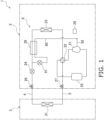
- the outdoor unit 2 mainly includes a compressor 21, a four-way switching valve 22, an outdoor heat exchanger 23, an outdoor expansion valve 24, an accumulator 25, a liquid shutoff valve 26, a gas shutoff valve 27, an economizer heat exchanger 28, and a control unit 29.
- the compressor 21 compresses a low-pressure gas refrigerant into a high-pressure gas refrigerant.
- the compressor 21 is driven by a compressor motor.
- the compressor 21 is a rotary compressor.
- intermediate injection is performed in which a part of the refrigerant having an intermediate pressure flowing from the outdoor heat exchanger 23 toward the outdoor expansion valve 24 is supplied to the compressor 21 compressing the refrigerant.
- the intermediate pressure is a predetermined pressure between a pressure (low pressure) of the gas refrigerant sucked into the compressor 21 and a pressure (high pressure) of the gas refrigerant discharged from the compressor 21.
- the four-way switching valve 22 switches connection states of internal pipes of the outdoor unit 2. When the air conditioner 1 performs the cooling operation, the four-way switching valve 22 achieves the connection state indicated by the broken line in FIG. 1 . When the air conditioner 1 performs the heating operation, the four-way switching valve 22 achieves the connection state indicated by the solid line in FIG. 1 .
- the outdoor heat exchanger 23 exchanges heat between the refrigerant circulating in the refrigerant circuit 6 and outdoor air.
- the outdoor heat exchanger 23 includes a refrigerant flow path through which the refrigerant flows, and a heat transfer fin in contact with the outdoor air.
- the outdoor heat exchanger 23 functions as a radiator (condenser) for the refrigerant during the cooling operation, and functions as a heat absorber (evaporator) for the refrigerant during the heating operation.
- the outdoor expansion valve 24 is an electric valve or an electromagnetic valve having an adjustable opening degree.
- the outdoor expansion valve 24 decompresses the refrigerant flowing through the internal pipes of the outdoor unit 2.
- the outdoor expansion valve 24 controls a flow rate of the refrigerant flowing through the internal pipe of the outdoor unit 2.
- the accumulator 25 is disposed in a pipe on a suction side of the compressor 21.
- the accumulator 25 separates a gas-liquid mixed refrigerant flowing in the refrigerant circuit 6 into a gas refrigerant and a liquid refrigerant and stores the liquid refrigerant.
- the gas refrigerant separated in the accumulator 25 is sent to a suction port of the compressor 21.
- the liquid shutoff valve 26 and the gas shutoff valve 27 are valves capable of shutting off the refrigerant flow path.
- the liquid shutoff valve 26 is disposed between the indoor heat exchanger 31 and the outdoor expansion valve 24.
- the gas shutoff valve 27 is disposed between the indoor heat exchanger 31 and the four-way switching valve 22.
- the liquid shutoff valve 26 and the gas shutoff valve 27 are opened and closed by an operator, for example, when the air conditioner 1 is installed.
- the economizer heat exchanger 28 is disposed between the outdoor heat exchanger 23 and the outdoor expansion valve 24.
- the economizer heat exchanger 28 exchanges heat between the refrigerant flowing from the outdoor heat exchanger 23 toward the outdoor expansion valve 24 and the refrigerant flowing through an economizer pipe 90.
- the economizer pipe 90 is a pipe branching from between the economizer heat exchanger 28 and the outdoor expansion valve 24 in the refrigerant circuit 6 and connected to an injection pipe 92 (described later).
- An economizer valve 91 is attached to the economizer pipe 90.
- the refrigerant flowing through the economizer pipe 90 is decompressed by the economizer valve 91, and then exchanges heat with the refrigerant flowing from the outdoor heat exchanger 23 toward the outdoor expansion valve 24 in the economizer heat exchanger 28.
- the refrigerant flowing from the outdoor heat exchanger 23 toward the outdoor expansion valve 24 and the refrigerant having exchanged heat in the economizer heat exchanger 28 are supplied to the injection pipe 92 as a refrigerant having an intermediate pressure.
- the control unit 29 is a computer that controls components of the outdoor unit 2.
- the control unit 29 mainly includes a calculation device and a storage device.
- the calculation device is, for example, a CPU or a GPU.
- the calculation device reads a program stored in the storage device and performs predetermined calculation processing in accordance with the program.
- the calculation device writes a result of the calculation processing in the storage device and reads information stored in the storage device in accordance with the program.
- the liquid-refrigerant connection pipe 4 and the gas-refrigerant connection pipe 5 are refrigerant pipes constructed on site when the air conditioner 1 including the refrigerant circuit 6 is installed at an installation location such as a building.
- the lengths and pipe diameters of the liquid-refrigerant connection pipe 4 and the gas-refrigerant connection pipe 5 are determined in accordance with installation conditions such as an installation location of the air conditioner 1 and a combination of the outdoor unit 2 and the indoor unit 3.
- the refrigerant flowing through the liquid-refrigerant connection pipe 4 may be a liquid or alternatively a gas-liquid two-phase refrigerant.
- the four-way switching valve 22 is switched to a state indicated by the solid line in FIG. 1 .
- a low-pressure gas refrigerant of the refrigeration cycle is sucked into the compressor 21, and discharged after compressed to a high-pressure refrigerant of the refrigeration cycle.
- the high-pressure gas refrigerant discharged from the compressor 21 is sent to the indoor heat exchanger 31 via the four-way switching valve 22, the gas shutoff valve 27, and the gas-refrigerant connection pipe 5.
- the high-pressure gas refrigerant sent to the indoor heat exchanger 31 is condensed by heat exchange with indoor air in the indoor heat exchanger 31, and becomes a high-pressure liquid refrigerant.
- the indoor air is thus heated.
- the high-pressure liquid refrigerant that has been condensed in the indoor heat exchanger 31 is sent to the outdoor expansion valve 24 through the liquid-refrigerant connection pipe 4 and the liquid shutoff valve 26.
- the refrigerant sent to the outdoor expansion valve 24 is decompressed by the outdoor expansion valve 24 to low pressure in the refrigeration cycle.
- the low-pressure refrigerant decompressed in the outdoor expansion valve 24 is sent to the outdoor heat exchanger 23.
- the low-pressure refrigerant sent to the outdoor heat exchanger 23 is evaporated by heat exchange with outdoor air in the outdoor heat exchanger 23, and becomes a low-pressure gas refrigerant.
- the low-pressure refrigerant that has been evaporated in the outdoor heat exchanger 23 is sucked again into the compressor 21 via the four-way switching valve 22 and the accumulator 25.
- the four-way switching valve 22 is switched to a state indicated by the broken line in FIG. 1 .
- a low-pressure gas refrigerant of the refrigeration cycle is sucked into the compressor 21, and discharged after compressed to a high-pressure refrigerant of the refrigeration cycle.
- the high-pressure gas refrigerant discharged from the compressor 21 is sent to the outdoor heat exchanger 23 through the four-way switching valve 22.
- the high-pressure gas refrigerant sent to the outdoor heat exchanger 23 is condensed by heat exchange with outdoor air in the outdoor heat exchanger 23, and becomes a high-pressure liquid refrigerant.
- the liquid refrigerant that has been condensed in the outdoor heat exchanger 23 is decompressed by the outdoor expansion valve 24 to low pressure in the refrigeration cycle.
- the low-pressure refrigerant decompressed in the outdoor expansion valve 24 is sent to the indoor heat exchanger 31 through the liquid shutoff valve 26 and the liquid-refrigerant connection pipe 4.
- the refrigerant sent to the indoor heat exchanger 31 is evaporated by heat exchange with indoor air in the indoor heat exchanger 31, and becomes a low-pressure gas refrigerant.
- the indoor air is thus cooled.
- the gas refrigerant that has been evaporated in the indoor heat exchanger 31 is sucked again into the compressor 21 via the gas-refrigerant connection pipe 5, the gas shutoff valve 27, the four-way switching valve 22, and the accumulator 25.
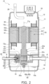
- the compressor 21 mainly includes a casing 10, a compression mechanism 15, a drive motor 16, a crankshaft 17, a suction pipe 19, a discharge pipe 20, an injection pipe 92, and an injection valve 93.
- the casing 10 includes a cylindrical trunk 11, a bowl-shaped top 12, and a bowl-shaped bottom 13.
- the top 12 is airtightly connected to an upper end of the trunk 11.
- the bottom 13 is airtightly connected to a lower end of the trunk 11.
- the casing 10 is formed with a rigid member that is less likely to be deformed and damaged due to changes in pressure and temperature in an internal space and an external space of the casing 10.
- the casing 10 is disposed with an axial direction of the cylindrical shape of the trunk 11 along a vertical direction.
- the casing 10 has an internal space including a lower part serving as an oil reservoir 10a that stores lubricating oil.
- the lubricating oil is refrigerator oil used to improve lubricity of a slider inside the casing 10.
- the casing 10 mainly accommodates the compression mechanism 15, the drive motor 16, and the crankshaft 17.
- the compression mechanism 15 is coupled to the drive motor 16 via the crankshaft 17.
- the suction pipe 19, the discharge pipe 20, and the injection pipe 92 are airtightly coupled to the casing 10 so as to penetrate the casing 10.
- the compression mechanism 15 mainly includes a front head 83, a cylinder 84, a rear head 85, a piston 81, and a bush 82.
- the front head 83, the cylinder 84, and the rear head 85 are integrally fastened by bolts or the like.
- a space above the compression mechanism 15 is a high-pressure space HS from which the refrigerant compressed by the compression mechanism 15 is discharged.
- the compression mechanism 15 is immersed in the lubricating oil stored in the oil reservoir 10a.
- the lubricating oil in the oil reservoir 10a is supplied to the slider inside the compression mechanism 15 by differential pressure or the like. Next, constituent elements of the compression mechanism 15 will be described.
- the cylinder 84 mainly includes a cylinder hole 84a, a suction hole 84b, a discharge cutout 84c, a bush accommodation hole 84d, a vane accommodation hole 84e, and an injection passage 84g.
- the cylinder 84 is located between the front head 83 and the rear head 85.
- a first cylinder end surface 86a which is an upper end surface of the cylinder 84, is in contact with a lower surface of the front head 83.
- a second cylinder end surface 86b which is a lower end surface of the cylinder 84, is in contact with an upper surface of the rear head 85.
- the cylinder hole 84a is a columnar hole that penetrates the cylinder 84 in the vertical direction from the first cylinder end surface 86a toward the second cylinder end surface 86b.
- the cylinder hole 84a is a space surrounded by a cylinder inner peripheral surface 86c which is an inner peripheral surface of the cylinder 84.
- the cylinder hole 84a accommodates the eccentric shaft 17a of the crankshaft 17 and the piston 81.
- the suction hole 84b is a hole that penetrates along a radial direction of the cylinder 84 from a cylinder outer peripheral surface 86d, which is an outer peripheral surface of the cylinder 84, toward the cylinder inner peripheral surface 86c.
- the discharge cutout 84c is a space formed by cutting out a part of the cylinder inner peripheral surface 86c without penetrating the cylinder 84 in the vertical direction.
- the discharge cutout 84c is formed on the side of the first cylinder end surface 86a.
- the bush accommodation hole 84d is a hole that penetrates the cylinder 84 in the vertical direction and is disposed between the suction hole 84b and the discharge cutout 84c when the cylinder 84 is viewed in the vertical direction.
- the bush accommodation hole 84d accommodates a part of a vane 81b and the bush 82.
- the vane accommodation hole 84e is a hole that penetrates the cylinder 84 in the vertical direction and communicates with the bush accommodation hole 84d.
- the vane accommodation hole 84e accommodates a part of the vane 81b.
- the injection passage 84g is a hole that penetrates along the radial direction of the cylinder 84 from the cylinder outer peripheral surface 86d toward the cylinder inner peripheral surface 86c. As shown in FIG. 3 , when the cylinder 84 is viewed in the vertical direction, the bush accommodation hole 84d is disposed between the suction hole 84b and the injection passage 84g. The injection valve 93 is disposed in the injection passage 84g. The injection passage 84g communicates with the injection pipe 92 on the side of the cylinder outer peripheral surface 86d, and communicates with the compression chamber 40 on the side of the cylinder inner peripheral surface 86c.
- the piston 81 is a substantially cylindrical member to be inserted into the cylinder hole 84a of the cylinder 84. An upper end surface of the piston 81 is in contact with the lower surface of the front head 83. A lower end surface of the piston 81 is in contact with the upper surface of the rear head 85.
- the piston 81 is inserted into the cylinder hole 84a of the cylinder 84 in a state of being fitted into the eccentric shaft 17a of the crankshaft 17. As a result, the piston 81 eccentrically rotates by an axial rotation of the crankshaft 17, and performs an orbital motion about an axis 17g of the crankshaft 17.
- the piston 81 revolves clockwise in top view of the compression mechanism 15.
- the vane 81b is accommodated in the bush accommodation hole 84d and the vane accommodation hole 84e of the cylinder 84.
- the vane 81b is formed integrally with the piston 81.
- the vane 81b extends along a radial direction of the piston 81 so as to protrude radially outward of the piston 81.
- the bush 82 supports the vane 81b while rotating in the bush accommodation hole 84d.
- the compression mechanism 15 includes a compression chamber 40 that is a space surrounded by the cylinder 84, the piston 81, the vane 81b, the front head 83, and the rear head 85.
- the compression chamber 40 is a part of the cylinder hole 84a, and is a space in which the refrigerant is compressed when the volume changes with the revolution of the piston 81.
- the lubricating oil in the oil reservoir 10a is supplied to the compression chamber 40.
- the compression chamber 40 is defined by the piston 81 and the vane 81b into a low-pressure chamber 40a communicating with the suction hole 84b and a high-pressure chamber 40b communicating with the discharge cutout 84c and the injection passage 84g.
- the low-pressure chamber 40a and the high-pressure chamber 40b are regions surrounded by the cylinder inner peripheral surface 86c and a piston outer peripheral surface 81c that is an outer peripheral surface of the piston 81.
- the volumes of the low-pressure chamber 40a and the high-pressure chamber 40b change in accordance with the position of the piston 81.
- the bush 82 includes a pair of substantially semi-cylindrical members.
- the bush 82 is accommodated in the bush accommodation hole 84d of the cylinder 84 so as to sandwich the vane 81b.
- the bush 82 is slidable with the cylinder 84.
- the front head 83 is a member that covers the first cylinder end surface 86a of the cylinder 84.
- the front head 83 is fastened to the casing 10 with a bolt or the like.
- the front head 83 includes an upper bearing 23a for supporting the crankshaft 17.
- the front head 83 includes a discharge port 23b.
- the discharge port 23b is a cylindrical hole that penetrates the front head 83 in the vertical direction.
- the discharge port 23b communicates with the discharge cutout 84c and the compression chamber 40 (high-pressure chamber 40b) on a lower side in the vertical direction.
- the discharge port 23b communicates with the high-pressure space HS on an upper side in the vertical direction.
- the discharge port 23b is a flow path for sending the refrigerant compressed by the compression mechanism 15 from the high-pressure chamber 40b to the high-pressure space HS.
- a discharge valve 23c that closes the discharge port 23b is attached to an upper surface of the front head 83.
- the discharge valve 23c is a valve for preventing backflow of the refrigerant from the high-pressure space HS to the high-pressure chamber 40b.
- the discharge valve 23c is lifted upward by the pressure of the refrigerant inside the discharge port 23b. As a result, the discharge port 23b opens, and the discharge port 23b communicates with the high-pressure space HS.
- the rear head 85 is a member that covers the second cylinder end surface 86b of the cylinder 84.
- the rear head 85 has a lower bearing 25a for supporting the crankshaft 17.
- the cylinder hole 84a of the cylinder 84 is closed by the front head 83 and the rear head 85.
- the drive motor 16 is a brushless DC motor accommodated in the casing 10 and disposed above the compression mechanism 15.
- the drive motor 16 mainly includes a stator 51 fixed to an inner wall surface of the casing 10 and a rotor 52 rotatably accommodated on an inner side of the stator 51.
- the stator 51 and the rotor 52 have an air gap therebetween.
- the stator 51 includes a stator core 61 and a pair of insulators 62 attached to both end surfaces of the stator core 61 in the vertical direction.
- the stator core 61 includes a cylindrical portion and a plurality of teeth (not shown) protruding radially inward from an inner peripheral surface of the cylindrical portion.
- a conductive wire is wound around the teeth of the stator core 61 together with the pair of insulators 62. As a result, a coil 72a is formed in each tooth of the stator core 61.
- a plurality of core cut portions (not shown) formed by cutting are provided from an upper end surface to a lower end surface of the stator 51 and at predetermined intervals in a circumferential direction.
- the core cut portion forms a motor cooling passage extending in the vertical direction between the trunk 11 and the stator 51.
- the rotor 52 has a rotor core 52a including a plurality of metal plates stacked in the vertical direction and a plurality of magnets 52b embedded in the rotor core 52a.
- the magnets 52b are arranged at equal intervals along a circumferential direction of the rotor core 52a.
- the rotor 52 has a rotation center coupled to the crankshaft 17 penetrating in the vertical direction.
- the rotor 52 is connected to the compression mechanism 15 via the crankshaft 17.
- the crankshaft 17 is accommodated in the casing 10 and is disposed with an axial direction of the crankshaft 17 along the vertical direction.
- the crankshaft 17 is coupled to the rotor 52 of the drive motor 16 and the piston 81 of the compression mechanism 15.
- the crankshaft 17 includes the eccentric shaft 17a.
- the eccentric shaft 17a is coupled to the piston 81 inserted into the cylinder hole 84a of the cylinder 84.
- An upper end of the crankshaft 17 is coupled to the rotor 52 of the drive motor 16.
- the crankshaft 17 is supported by the upper bearing 23a of the front head 83 and a lower bearing 25a of the rear head 85.
- the crankshaft 17 rotates about the axis 17g.
- the suction pipe 19 is a pipe that penetrates the trunk 11 of the casing 10. An end of the suction pipe 19 inside of the casing 10 is fitted into the suction hole 84b of the cylinder 84. An end of the suction pipe 19 outside the casing 10 is connected to the refrigerant circuit 6. The suction pipe 19 allows the refrigerant to be supplied from the refrigerant circuit 6 to the compression mechanism 15.
- the discharge pipe 20 is a pipe that penetrates the top 12 of the casing 10. An end of the discharge pipe 20 inside the casing 10 is located in a space above the drive motor 16. An end of the discharge pipe 20 outside the casing 10 is connected to the refrigerant circuit 6.
- the discharge pipe 20 allows the refrigerant compressed by the compression mechanism 15 to be supplied to the refrigerant circuit 6.
- the injection pipe 92 is a pipe that penetrates the trunk 11 of the casing 10. An end of the injection pipe 92 inside the casing 10 is connected to the injection valve 93 disposed in the injection passage 84g of the cylinder 84. An end of the injection pipe 92 outside the casing 10 is connected to the economizer pipe 90. The injection pipe 92 allows the refrigerant in the economizer pipe 90 to be supplied to the injection passage 84g.
- the injection valve 93 performs intermediate injection and prevents a reverse flow of the refrigerant from the compression chamber 40 to the injection passage 84g.
- the injection valve 93 mainly includes a valve body 94, a valve presser 95, and a valve seat 96.
- the valve presser 95 and the valve seat 96 are fixed to the cylinder 84 by being press-fitted into the injection passage 84g.
- the valve presser 95 and the valve seat 96 are disposed to be separated from each other along a first direction D1 in which the injection passage 84g extends.
- the space between the valve presser 95 and the valve seat 96 is a first space 97 in which the valve body 94 is accommodated so as to be movable along the first direction D1.
- the first space 97 is a cylindrical space.
- the valve presser 95 is disposed closer to the injection pipe 92 than the valve body 94.
- the valve seat 96 is disposed closer to the compression chamber 40 than the valve body 94.
- the injection passage 84g is a circular hole having different inner diameters along the first direction D1.
- the injection passage 84g has the largest inner diameter at an end closer to the cylinder outer peripheral surface 86d, and has the smallest inner diameter at an end closer to the cylinder inner peripheral surface 86c. Specifically, the inner diameter of the injection passage 84g increases from the cylinder inner peripheral surface 86c toward the cylinder outer peripheral surface 86d.
- the valve body 94 is a circular flat plate.
- the valve body 94 is formed with spring steel such as GIN6 (stainless steel hardened by Hitachi Metals, Ltd.).
- GIN6 stainless steel hardened by Hitachi Metals, Ltd.
- a circular second hole 94a is formed at a center of the valve body 94.
- the valve body 94 has an annular peripheral edge 94b located around the second hole 94a. In FIG. 8 , the peripheral edge 94b is indicated as a hatched region.
- the valve body 94 is disposed in the first space 97 so as to be movable along the first direction D1.
- the valve presser 95 is press-fitted on the side of the cylinder outer peripheral surface 86d of the injection passage 84g.
- the valve presser 95 have different outer diameters along the first direction D1. A part of the valve presser 95 protrudes outward from the cylinder outer peripheral surface 86d.
- the injection pipe 92 is inserted into the valve presser 95 from the side of the cylinder outer peripheral surface 86d.
- the injection pipe 92 is fixed to the valve presser 95.
- an O ring 92a attached to the injection pipe 92 separates the injection passage 84g and the high-pressure space HS.
- the valve presser 95 has a first hole 95a, a closing portion 95b, and a buffer space 95c.
- the first hole 95a is a hole through which the refrigerant passes, and is closed by the valve body 94 when the refrigerant flows out of the compression chamber 40.
- the first hole 95a penetrates the valve presser 95 along the first direction D1.
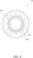
- the closing portion 95b is an annular region located at a center of the valve presser 95 when the valve presser 95 is viewed in the first direction D1 from the cylinder inner peripheral surface 86c.
- the plurality of first holes 95a is formed around the closing portion 95b.
- the buffer space 95c is formed such that the center of the buffer space 95c overlaps a center of the closing portion 95b along the first direction D1.
- the closing portion 95b is indicated as a hatched region.
- first holes 95a are arranged in a circular shape.
- An outer diameter of the closing portion 95b is larger than a diameter of the second hole 94a of the valve body 94.
- the diameter of the first hole 95a is smaller than a width of the peripheral edge 94b of the valve body 94 (dimension in a radial direction of the valve body 94).
- the buffer space 95c is a space formed in communication with the first space 97 such that the refrigerant flowing into the first space 97 from the compression chamber 40 flows in before reaching the first hole 95a.
- the buffer space 95c is formed closer to the injection pipe 92 than the second hole 94a.
- the buffer space 95c is a columnar concave portion formed on a surface of the closing portion 95b facing the valve body 94.
- the buffer space 95c is formed so as to be located on a center axis CL of the first space 97 together with the second hole 94a (see FIG. 7 ).
- the buffer space 95c is formed such that an area of a circular opening 95co facing the valve body 94 is smaller than a flow path area of the second hole 94a.
- a ratio of the area of the opening 95co of the buffer space 95c facing the valve body 94 to the flow path area of the second hole 94a is preferably 0.5 or more and 1.0 or less.
- the opening 95co is preferably formed so as to be entirely exposed to the cylinder inner peripheral surface 86c through the second hole 94a. In other words, the opening 95co is preferably formed so as not to generate a region overlapping the peripheral edge 94b when viewed from the cylinder inner peripheral surface 86c along the first direction D1.
- a ratio of a depth d (see FIG. 7 ) of the buffer space 95c in the first direction D1 of the first space 97 to a length L of the first hole 95a in the first direction D1 is preferably 0.3 or more and 0.6 or less.
- a ratio of a volume of a third hole 96a (described later) formed in the first space 97 and the valve seat 96 to a volume of the buffer space 95c is preferably 0.2 or more and 0.8 or less.
- the valve presser 95 restricts movement of the valve body 94 toward the injection pipe 92. In other words, when moving in the first direction D1 toward the injection pipe 92, the valve body 94 is movable until hitting the valve presser 95. In a state where the valve body 94 is in contact with the valve presser 95, the first hole 95a of the valve presser 95 is closed by the peripheral edge 94b of the valve body 94. At this time, the second hole 94a of the valve body 94 is closed by the closing portion 95b of the valve presser 95. In a state where the valve body 94 is separated from the valve presser 95, the first hole 95a of the valve presser 95 is not closed by the peripheral edge 94b of the valve body 94. At this time, the second hole 94a of the valve body 94 is not closed by the closing portion 95b of the valve presser 95.
- the first hole 95a of the valve presser 95 is opened and closed by the valve body 94.
- the second hole 94a of the valve body 94 and the first hole 95a of the valve presser 95 are closed, and thus, the injection valve 93 is closed (see FIG. 5 ). Therefore, the refrigerant in the injection pipe 92 cannot flow into the compression chamber 40 through the first hole 95a and the second hole 94a.
- the valve seat 96 restricts movement of the valve body 94 toward the compression chamber 40.
- the valve seat 96 is press-fitted on the side of the cylinder inner peripheral surface 86c of the injection passage 84g.
- the valve seat 96 has a cylindrical shape whose outer diameter is substantially constant along the first direction D1.
- the valve seat 96 has the third hole 96a.
- the third hole 96a penetrates the valve seat 96 along the first direction D1.
- the valve seat 96 allows the first space 97 and the compression chamber 40 to communicate with each other.
- the third hole 96a includes an enlarged portion 96ae having an inner diameter enlarged from the compression chamber 40 to an opening closer to the injection pipe 92.
- the smallest inner diameter of the third hole 96a is substantially the same as an inner diameter of the second hole 94a of the valve body 94.
- the inner diameter of the opening of the enlarged portion 96ae which is the largest inner diameter of the third hole 96a, is larger than the inner diameter of the second hole 94a of the valve body 94.
- the third hole 96a always communicates with the compression chamber 40 via the injection passage 84g.
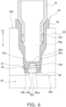
- valve body 94 When moving in the first direction D1 toward the compression chamber 40, the valve body 94 is movable until hitting the valve seat 96. In a state where the valve body 94 is in contact with the valve seat 96, the second hole 94a of the valve body 94 communicates with the third hole 96a of the valve seat 96. When the valve body 94 is in contact with the valve seat 96, since the valve body 94 is separated from the valve presser 95, the injection valve 93 is opened (see FIG. 6 ).
- the compression chamber 40 (low-pressure chamber 40a) communicating with the suction hole 84b gradually increases in volume.
- the low-pressure refrigerant flows from outside the casing 10 into the low-pressure chamber 40a via the suction pipe 19.
- the low-pressure chamber 40a becomes the high-pressure chamber 40b communicating with the discharge cutout 84c, the high-pressure chamber 40b gradually decreases in volume and disappears, and then a new low-pressure chamber 40a is formed.
- the low-pressure refrigerant flowing from the suction pipe 19 into the low-pressure chamber 40a via the suction hole 84b is compressed in the compression chamber 40 (high-pressure chamber 40b). While the refrigerant is compressed in the compression chamber 40, the vane 81b is held between the pair of bushes so as to be movable forward and backward.
- the high-pressure refrigerant compressed in the high-pressure chamber 40b is discharged into the high-pressure space HS via the discharge cutout 84c and the discharge port 23b.
- the refrigerant discharged into the high-pressure space HS flows upward through the motor cooling passage of the drive motor 16, and then is discharged from the discharge pipe 20 to the outside of the casing 10.
- the intermediate injection is performed when the refrigerant having an intermediate pressure is supplied from the injection passage 84g to the high-pressure chamber 40b in a state where the injection valve 93 is opened.
- the intermediate injection is performed when the pressure in the compression chamber 40 (high-pressure chamber 40b) is lower than the intermediate pressure, and is not performed when the pressure in the compression chamber 40 (high-pressure chamber 40b) is equal to or higher than the intermediate pressure.
- the injection valve 93 repeats opening and closing as described below.
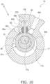
- the compression chamber 40 is not defined into the low-pressure chamber 40a and the high-pressure chamber 40b by the piston 81, and the compression chamber 40 communicates with both the suction hole 84b and the injection passage 84g. Therefore, the compression chamber 40 is filled with the low-pressure refrigerant flowing from the suction hole 84b. Since the pressure in the compression chamber 40 is lower than the intermediate pressure, the intermediate pressure causes the valve body 94 to move toward the valve seat 96 and hit the valve seat 96. As a result, the injection valve 93 is opened, and the intermediate injection is performed (see FIG. 6 ).
- the piston 81 When the piston 81 revolves from the state shown in FIG. 10 , the piston 81 closes the opening of the suction hole 84b in the cylinder inner peripheral surface 86c as shown in FIG. 11 .
- the compression chamber 40 is defined into the low-pressure chamber 40a and the high-pressure chamber 40b by the piston 81, and the high-pressure chamber 40b communicates with the injection passage 84g.
- the piston 81 further revolves and the pressure in the high-pressure chamber 40b increases, the pressure in the high-pressure chamber 40b becomes equal to or higher than the intermediate pressure.
- the valve body 94 moves toward the valve presser 95 by the pressure of the high-pressure chamber 40b and hits the valve presser 95.
- the injection valve 93 is closed, and the intermediate injection ends (see FIG. 5 ).
- the refrigerant in the compression chamber 40 flows into the first space 97 immediately before the end of the intermediate injection. At least a part of the refrigerant flowing into the first space 97 flows into the buffer space 95c before passing through the second hole 94a of the valve body 94 and reaching the first hole 95a as indicated by an arrow in FIG. 7 . Accordingly, a time lag is generated between when the refrigerant flows into the first space 97 and when the refrigerant reaches the first hole 95a.
- the valve body 94 hitting the valve seat 96 in the intermediate injection can move toward the valve presser 95 during this time lag to close the first hole 95a of the valve presser 95.
- the inner diameter of the opening of the enlarged portion 96ae formed in the third hole 96a is formed to be larger than the inner diameter of the second hole 94a formed in the valve body 94.
- the piston 81 When the piston 81 further revolves, as shown in FIG. 12 , the piston 81 closes the opening of the injection passage 84g in the cylinder inner peripheral surface 86c. At this time, the compression chamber 40 is defined into the low-pressure chamber 40a and the high-pressure chamber 40b by the piston 81, and the low-pressure chamber 40a communicates with the suction hole 84b. Therefore, the low-pressure chamber 40a is filled with the low-pressure refrigerant flowing from the suction hole 84b.
- the injection valve 93 is opened and closed by the pressure difference between the refrigerant in the compression chamber 40 and the refrigerant having an intermediate pressure in the injection pipe 92.
- the injection valve 93 is opened, and the intermediate injection is performed.
- the injection valve 93 is closed, and the intermediate injection is not performed.
- the injection valve 93 can perform the intermediate injection and suppress the refrigerant from flowing out of the compression chamber 40 into the injection passage 84g when the intermediate injection is not performed. Therefore, since a sufficient amount of the refrigerant having an intermediate pressure is supplied to the compression chamber 40 while the compressor 21 is operating, the compressor 21 can obtain a higher compression rate than in a case where the injection valve 93 is not provided.
- the compressor 21 includes the compression mechanism 15, the injection valve 93, and the injection pipe 92.
- the compression mechanism 15 includes the compression chamber 40 in which the refrigerant is compressed.
- the injection valve 93 is disposed in the injection passage 84g that communicates with the compression chamber 40.
- the injection pipe 92 allows the refrigerant to be supplied to the injection passage 84g.
- the injection valve 93 includes the valve body 94, the valve presser 95, and the valve seat 96.
- the valve body 94 is disposed so as to be movable along the first direction D1.
- the valve presser 95 is disposed closer to the injection pipe 92 than the valve body 94, and restricts the movement of the valve body 94 toward the injection pipe 92.
- the valve seat 96 is disposed closer to the compression chamber 40 than the valve body 94, and restricts the movement of the valve body 94 toward the compression chamber 40.
- the valve presser 95 has the first hole 95a that is closed by the valve body 94 when the refrigerant passes and flows out of the compression chamber 40.
- the valve body 94 has the second hole 94a through which the refrigerant passes.
- the compressor 21 has the buffer space 95c that communicates with the first space 97 in which the valve body 94 is accommodated between the valve presser 95 and the valve seat 96, and into which the refrigerant flowing from the compression chamber 40 into the first space 97 flows before reaching the first hole 95a.
- the injection valve 93 that moves the plate-shaped valve body 94 using the pressure difference between the compression chamber 40 and the injection passage 84g has a simpler structure than a check valve that moves the valve body 94 with a spring member.
- the valve body 94 does not move quickly in the first space 97, and the high-pressure refrigerant flows out from the compression chamber 40 to the injection passage 84g immediately before the intermediate injection ends, and there is a possibility that a high compression rate cannot be achieved.
- the compressor 21 has a simple structure in which the injection valve 93 does not use a spring member, and can still obtain a high compression efficiency by suppressing the outflow of the refrigerant from the compression chamber 40 to the injection passage 84g immediately before the end of the intermediate injection.
- the buffer space 95c is formed closer to the injection pipe 92 than the second hole 94a.
- the buffer space 95c is a concave portion formed on a surface of the valve presser 95 facing the valve body 94.
- the first space 97 has a cylindrical shape.
- the valve body 94 is a circular flat plate having a second hole 94a at the center.
- the buffer space 95c is located on the center axis CL of the first space 97 together with the second hole 94a.
- the ratio of the area of the opening 95co of the buffer space 95c facing the valve body 94 to the flow path area of the second hole 94a is 0.5 or more and 1.0 or less.
- the ratio between the depth d of the buffer space 95c in the first direction D1 of the first space 97 and the length L of the first hole 95a in the first direction D1 is 0.3 or more and 0.6 or less.
- the valve seat 96 has the third hole 96a that allows the first space 97 and the compression chamber 40 to communicate with each other.
- the ratio pf the volumes of the first space 97 and the third hole 96a to the volume of the buffer space 95c is 0.2 or more and 0.8 or less.
- the air conditioner 1 includes the compressor 21.
- the air conditioner 1 including the compressor 21 having a high compression efficiency can perform an air conditioning operation with high efficiency.
- the injection valve 93 can also be applied to a compressor other than the rotary compressor.
- the injection valve 93 can also be applied to a scroll compressor.
- Patent Literature 1 WO 2017/221571 A
Landscapes
- Engineering & Computer Science (AREA)
- Mechanical Engineering (AREA)
- General Engineering & Computer Science (AREA)
- Physics & Mathematics (AREA)
- Thermal Sciences (AREA)
- Applications Or Details Of Rotary Compressors (AREA)
- Compressor (AREA)
Abstract
Description
- The present disclosure relates to a compressor and an air conditioner.
- Patent Literature 1 (
WO 2017/221571 A ) discloses a compressor including an injection mechanism that causes a refrigerant having an intermediate pressure to flow into a compression chamber. The injection mechanism includes a check valve that suppresses a flow of the refrigerant from the compression chamber to an injection passage. The check valve includes a valve element and a spring member. When the refrigerant in the compression chamber has a high pressure, the check valve regulates outflow of the refrigerant from the compression chamber to the injection passage. When the refrigerant in the compression chamber has a low pressure, the check valve allows inflow of the refrigerant having an intermediate pressure from the injection passage to the compression chamber. - As a check valve having a form different from the above check valve, a check valve is known that moves a plate-shaped valve element accommodated in an accommodation space by using a pressure difference of the refrigerant between inside and outside the compression chamber. A check valve having a plate-shaped valve element has a simpler structure than a check valve having a spring member. However, depending on the weight and shape of the valve element, the valve element does not move quickly even when the refrigerant in the compression chamber becomes high pressure, and the high-pressure refrigerant flows out of the compression chamber, which causes a problem that a high compression efficiency cannot be obtained.
- The present disclosure proposes a compressor capable of obtaining a high compression efficiency with a simple structure, and an air conditioner including the compressor.
- A compressor according to a first aspect includes a compression mechanism, an injection valve, and an injection pipe. The compression mechanism includes a compression chamber in which a refrigerant is compressed. The injection valve is disposed in an injection passage that communicates with the compression chamber. The injection pipe allows the refrigerant to be supplied to the injection passage.
- The injection valve includes a valve body, a valve presser, and a valve seat. The valve body is disposed so as to be movable along a first direction. The valve presser is disposed closer to the injection pipe than the valve body, and restricts movement of the valve body toward the injection pipe. The valve seat is disposed closer to the compression chamber than the valve body, and restricts movement of the valve body toward the compression chamber. The valve presser has a first hole through which the refrigerant flowing out of the compression chamber passes. The valve body has a second hole through which the refrigerant passes.
- The compressor has a buffer space that communicates with a first space, in which the valve body is accommodated between the valve presser and the valve seat, and into which the refrigerant flowing from the compression chamber into the first space flows.
- In the compressor, at least a part of the refrigerant flowing into the first space immediately before an end of intermediate injection in which the refrigerant having an intermediate pressure is supplied to the compressor flows into the buffer space before reaching the first hole. Accordingly, a time lag is generated between when the refrigerant flows into the first space and when the refrigerant reaches the first hole. The valve body hitting the valve seat in the intermediate injection can move toward the valve presser during this time lag and suppress the outflow of the refrigerant from the compression chamber to the injection passage.
- A compressor according to a second aspect includes a compression mechanism, an injection valve, and an injection pipe. The compression mechanism includes a compression chamber in which a refrigerant is compressed. The injection valve is disposed in an injection passage that communicates with the compression chamber. The injection pipe allows the refrigerant to be supplied to the injection passage.
- The injection valve includes a valve body, a valve presser, and a valve seat. The valve body is disposed so as to be movable along a first direction. The valve presser is disposed closer to the injection pipe than the valve body, and restricts movement of the valve body toward the injection pipe. The valve seat is disposed closer to the compression chamber than the valve body, and restricts movement of the valve body toward the compression chamber. The valve presser has a first hole that is closed by the valve body when the refrigerant passes and flows out of the compression chamber. The valve body has a second hole through which the refrigerant passes.
- The compressor has a buffer space that communicates with the first space, in which the valve body is accommodated between the valve presser and the valve seat, and into which the refrigerant flowing from the compression chamber into the first space flows before reaching the first hole.
- In the compressor, at least a part of the refrigerant flowing into the first space immediately before an end of intermediate injection in which the refrigerant having an intermediate pressure is supplied to the compressor flows into the buffer space before reaching the first hole. Accordingly, a time lag is generated between when the refrigerant flows into the first space and when the refrigerant reaches the first hole. The valve body hitting the valve seat in the intermediate injection can move toward the valve presser during this time lag and suppress the outflow of the refrigerant from the compression chamber to the injection passage.
- As described above, this compressor has a simple structure in which the injection valve does not use a spring member, and can still obtain a high compression efficiency by suppressing the outflow of the refrigerant from the compression chamber to the injection passage immediately before the end of the intermediate injection.
- A compressor according to a third aspect is the compressor according to the first or second aspect, in which the buffer space is formed closer to the injection pipe than the second hole.
- A compressor according to a fourth aspect is the compressor according to any one of the first to third aspects, in which the buffer space is a concave portion formed on a surface of the valve presser facing the valve body.
- A compressor according to a fifth aspect is the compressor according to any one of the first to fourth aspects, in which the first space has a cylindrical shape. The valve body is a circular flat plate having a second hole at a center. The buffer space is located on a center axis of the first space together with the second hole.
- As a result, since the buffer space and the second hole are located on the center axis, most of the refrigerant passing through the second hole can flow into the buffer space, and the outflow of the refrigerant from the compression chamber is effectively suppressed. Therefore, in this compressor, a high compression efficiency can be obtained.
- A compressor according to a sixth aspect is the compressor according to any one of the first to fifth aspects, in which a ratio of an area of an opening of the buffer space facing the valve body to a flow path area of the second hole is 0.5 or more and 1.0 or less.
- As a result, since most of the refrigerant passing through the second hole can flow into the buffer space, the outflow of the refrigerant from the compression chamber is effectively suppressed. Therefore, in this compressor, a high compression efficiency can be obtained.
- A compressor according to a seventh aspect is the compressor according to any one of the first to sixth aspects, in which a ratio of a depth of the buffer space in the first direction of the first space to a length of the first hole in the first direction is 0.3 or more and 0.6 or less.
- As a result, since most of the refrigerant passing through the second hole can flow into the buffer space, a time lag from when the refrigerant flows into the first space to when the refrigerant reaches the first hole is reliably generated, and the outflow of the refrigerant from the compression chamber is effectively suppressed. Therefore, in this compressor, a high compression efficiency can be obtained.
- A compressor according to an eighth aspect is the compressor according to any one of the first to seventh aspects, in which the valve seat has a third hole that allows the first space and the compression chamber to communicate with each other. A ratio of volumes of the first space and the third hole to a volume of the buffer space is 0.2 or more and 0.8 or less.
- As a result, since most of the refrigerant flowing into the first space can flow into the buffer space, a time lag from when the refrigerant flows into the first space to when the refrigerant reaches the first hole is reliably generated, and the outflow of the refrigerant from the compression chamber is effectively suppressed. Therefore, in this compressor, a high compression efficiency can be obtained.
- A compressor according to a ninth aspect includes a compression chamber and a valve. In the compression chamber, the refrigerant is compressed. The valve is disposed in an injection passage that communicates with the compression chamber. The valve includes a valve body, a valve presser, and a valve seat. The valve body is accommodated in the first space. The valve presser has a first hole communicating with the first space and defines the first space. The valve seat has a third hole communicating with the first space and defines the first space.
- The valve presser has a concave portion that is a buffer space provided with an opening on a surface facing the first space.
- In the compressor, at least a part of the refrigerant flowing into the first space immediately before an end of intermediate injection in which the refrigerant having an intermediate pressure is supplied to the compressor flows into the buffer space before reaching the first hole. Accordingly, a time lag is generated between when the refrigerant flows into the first space and when the refrigerant reaches the first hole. The valve body hitting the valve seat in the intermediate injection can move toward the valve presser during this time lag and suppress the outflow of the refrigerant from the compression chamber to the injection passage.
- A compressor according to a tenth aspect is the compressor according to the ninth aspect, in which the valve body is a circular flat plate having a second hole. The first space has a cylindrical shape. The concave portion is located on a center axis of the first space together with the second hole.
- A compressor according to an eleventh aspect is the compressor according to the ninth or tenth aspect, in which the buffer space is a space into which the refrigerant flowing into the first space flows.
- An air conditioner according to a twelfth aspect includes the compressor according to any one of the first to eleventh aspects.
- This air conditioner including the compressor having a high compression efficiency can perform an air conditioning operation with high efficiency.
-
-
FIG. 1 is a schematic configuration diagram of an air conditioner 1 according to an embodiment. -
FIG. 2 is a longitudinal sectional view of acompressor 21. -
FIG. 3 is a sectional view of acompression mechanism 15 taken along line A-A inFIG. 2 . -
FIG. 4 is an external view of acylinder 84. -
FIG. 5 is a sectional view showing a configuration of aninjection valve 93 in a first state. -
FIG. 6 is a sectional view showing a configuration of theinjection valve 93 in a second state. -
FIG. 7 is an enlarged sectional view of a periphery of afirst space 97 in the second state. -
FIG. 8 is a plan view of avalve body 94 when viewed in a first direction D1. -
FIG. 9 is a plan view of avalve presser 95 when viewed in the first direction D1 from a cylinder innerperipheral surface 86c. -
FIG. 10 is a sectional view of thecompression mechanism 15 when apiston 81 is located at a top dead center. -
FIG. 11 is a sectional view of thecompression mechanism 15 when thepiston 81 closes asuction hole 84b. -
FIG. 12 is a sectional view of thecompression mechanism 15 when thepiston 81 closes aninjection passage 84g. - An air conditioner 1 including a
compressor 21 according to one embodiment of the present disclosure will be described with reference to the drawings. - As shown in
FIG. 1 , the air conditioner 1 is a device capable of performing cooling and heating of a room of a building or the like by performing a vapor compression refrigeration cycle. The air conditioner 1 mainly includes anoutdoor unit 2, an indoor unit 3, a liquid-refrigerant connection pipe 4, and a gas-refrigerant connection pipe 5. The liquid-refrigerant connection pipe 4 and the gas-refrigerant connection pipe 5 connect theoutdoor unit 2 and the indoor unit 3. Theoutdoor unit 2 and the indoor unit 3 are connected via the liquid-refrigerant connection pipe 4 and the gas-refrigerant connection pipe 5. This configures a vaporcompression refrigerant circuit 6 of the air conditioner 1. - The indoor unit 3 is installed indoors (in a living room, a space above a ceiling, and the like) and constitute a part of the
refrigerant circuit 6. The indoor unit 3 mainly includes anindoor heat exchanger 31. In a cooling operation, theindoor heat exchanger 31 functions as a heat absorber (evaporator) for the refrigerant to cool indoor air, and in a heating operation, theindoor heat exchanger 31 functions as a radiator (condenser) for the refrigerant to heat indoor air. A liquid side of theindoor heat exchanger 31 is connected to the liquid-refrigerant connection pipe 4. A gas side of theindoor heat exchanger 31 is connected to the gas-refrigerant connection pipe 5. - The
outdoor unit 2 is installed outdoors (on a rooftop of a building, near a wall surface of a building, and the like) and constitutes a part of therefrigerant circuit 6. Theoutdoor unit 2 mainly includes acompressor 21, a four-way switching valve 22, anoutdoor heat exchanger 23, anoutdoor expansion valve 24, anaccumulator 25, aliquid shutoff valve 26, agas shutoff valve 27, aneconomizer heat exchanger 28, and acontrol unit 29. - The
compressor 21 compresses a low-pressure gas refrigerant into a high-pressure gas refrigerant. Thecompressor 21 is driven by a compressor motor. Thecompressor 21 is a rotary compressor. In thecompressor 21, intermediate injection is performed in which a part of the refrigerant having an intermediate pressure flowing from theoutdoor heat exchanger 23 toward theoutdoor expansion valve 24 is supplied to thecompressor 21 compressing the refrigerant. The intermediate pressure is a predetermined pressure between a pressure (low pressure) of the gas refrigerant sucked into thecompressor 21 and a pressure (high pressure) of the gas refrigerant discharged from thecompressor 21. - The four-
way switching valve 22 switches connection states of internal pipes of theoutdoor unit 2. When the air conditioner 1 performs the cooling operation, the four-way switching valve 22 achieves the connection state indicated by the broken line inFIG. 1 . When the air conditioner 1 performs the heating operation, the four-way switching valve 22 achieves the connection state indicated by the solid line inFIG. 1 . - The
outdoor heat exchanger 23 exchanges heat between the refrigerant circulating in therefrigerant circuit 6 and outdoor air. Theoutdoor heat exchanger 23 includes a refrigerant flow path through which the refrigerant flows, and a heat transfer fin in contact with the outdoor air. Theoutdoor heat exchanger 23 functions as a radiator (condenser) for the refrigerant during the cooling operation, and functions as a heat absorber (evaporator) for the refrigerant during the heating operation. - The
outdoor expansion valve 24 is an electric valve or an electromagnetic valve having an adjustable opening degree. Theoutdoor expansion valve 24 decompresses the refrigerant flowing through the internal pipes of theoutdoor unit 2. Theoutdoor expansion valve 24 controls a flow rate of the refrigerant flowing through the internal pipe of theoutdoor unit 2. - The
accumulator 25 is disposed in a pipe on a suction side of thecompressor 21. Theaccumulator 25 separates a gas-liquid mixed refrigerant flowing in therefrigerant circuit 6 into a gas refrigerant and a liquid refrigerant and stores the liquid refrigerant. The gas refrigerant separated in theaccumulator 25 is sent to a suction port of thecompressor 21. - The
liquid shutoff valve 26 and thegas shutoff valve 27 are valves capable of shutting off the refrigerant flow path. Theliquid shutoff valve 26 is disposed between theindoor heat exchanger 31 and theoutdoor expansion valve 24. Thegas shutoff valve 27 is disposed between theindoor heat exchanger 31 and the four-way switching valve 22. Theliquid shutoff valve 26 and thegas shutoff valve 27 are opened and closed by an operator, for example, when the air conditioner 1 is installed. - The
economizer heat exchanger 28 is disposed between theoutdoor heat exchanger 23 and theoutdoor expansion valve 24. Theeconomizer heat exchanger 28 exchanges heat between the refrigerant flowing from theoutdoor heat exchanger 23 toward theoutdoor expansion valve 24 and the refrigerant flowing through aneconomizer pipe 90. Theeconomizer pipe 90 is a pipe branching from between theeconomizer heat exchanger 28 and theoutdoor expansion valve 24 in therefrigerant circuit 6 and connected to an injection pipe 92 (described later). Aneconomizer valve 91 is attached to theeconomizer pipe 90. The refrigerant flowing through theeconomizer pipe 90 is decompressed by theeconomizer valve 91, and then exchanges heat with the refrigerant flowing from theoutdoor heat exchanger 23 toward theoutdoor expansion valve 24 in theeconomizer heat exchanger 28. The refrigerant flowing from theoutdoor heat exchanger 23 toward theoutdoor expansion valve 24 and the refrigerant having exchanged heat in theeconomizer heat exchanger 28 are supplied to theinjection pipe 92 as a refrigerant having an intermediate pressure. - The
control unit 29 is a computer that controls components of theoutdoor unit 2. Thecontrol unit 29 mainly includes a calculation device and a storage device. The calculation device is, for example, a CPU or a GPU. The calculation device reads a program stored in the storage device and performs predetermined calculation processing in accordance with the program. The calculation device writes a result of the calculation processing in the storage device and reads information stored in the storage device in accordance with the program. - The liquid-
refrigerant connection pipe 4 and the gas-refrigerant connection pipe 5 are refrigerant pipes constructed on site when the air conditioner 1 including therefrigerant circuit 6 is installed at an installation location such as a building. The lengths and pipe diameters of the liquid-refrigerant connection pipe 4 and the gas-refrigerant connection pipe 5 are determined in accordance with installation conditions such as an installation location of the air conditioner 1 and a combination of theoutdoor unit 2 and the indoor unit 3. The refrigerant flowing through the liquid-refrigerant connection pipe 4 may be a liquid or alternatively a gas-liquid two-phase refrigerant. - An operation of the air conditioner 1 during the cooling operation and the heating operation will be described with reference to
FIG. 1 . - In a case where the air conditioner 1 performs the heating operation, the four-
way switching valve 22 is switched to a state indicated by the solid line inFIG. 1 . In therefrigerant circuit 6, a low-pressure gas refrigerant of the refrigeration cycle is sucked into thecompressor 21, and discharged after compressed to a high-pressure refrigerant of the refrigeration cycle. The high-pressure gas refrigerant discharged from thecompressor 21 is sent to theindoor heat exchanger 31 via the four-way switching valve 22, thegas shutoff valve 27, and the gas-refrigerant connection pipe 5. The high-pressure gas refrigerant sent to theindoor heat exchanger 31 is condensed by heat exchange with indoor air in theindoor heat exchanger 31, and becomes a high-pressure liquid refrigerant. The indoor air is thus heated. The high-pressure liquid refrigerant that has been condensed in theindoor heat exchanger 31 is sent to theoutdoor expansion valve 24 through the liquid-refrigerant connection pipe 4 and theliquid shutoff valve 26. The refrigerant sent to theoutdoor expansion valve 24 is decompressed by theoutdoor expansion valve 24 to low pressure in the refrigeration cycle. The low-pressure refrigerant decompressed in theoutdoor expansion valve 24 is sent to theoutdoor heat exchanger 23. The low-pressure refrigerant sent to theoutdoor heat exchanger 23 is evaporated by heat exchange with outdoor air in theoutdoor heat exchanger 23, and becomes a low-pressure gas refrigerant. The low-pressure refrigerant that has been evaporated in theoutdoor heat exchanger 23 is sucked again into thecompressor 21 via the four-way switching valve 22 and theaccumulator 25. - In a case where the air conditioner 1 performs the cooling operation, the four-
way switching valve 22 is switched to a state indicated by the broken line inFIG. 1 . In therefrigerant circuit 6, a low-pressure gas refrigerant of the refrigeration cycle is sucked into thecompressor 21, and discharged after compressed to a high-pressure refrigerant of the refrigeration cycle. The high-pressure gas refrigerant discharged from thecompressor 21 is sent to theoutdoor heat exchanger 23 through the four-way switching valve 22. The high-pressure gas refrigerant sent to theoutdoor heat exchanger 23 is condensed by heat exchange with outdoor air in theoutdoor heat exchanger 23, and becomes a high-pressure liquid refrigerant. The liquid refrigerant that has been condensed in theoutdoor heat exchanger 23 is decompressed by theoutdoor expansion valve 24 to low pressure in the refrigeration cycle. The low-pressure refrigerant decompressed in theoutdoor expansion valve 24 is sent to theindoor heat exchanger 31 through theliquid shutoff valve 26 and the liquid-refrigerant connection pipe 4. The refrigerant sent to theindoor heat exchanger 31 is evaporated by heat exchange with indoor air in theindoor heat exchanger 31, and becomes a low-pressure gas refrigerant. The indoor air is thus cooled. The gas refrigerant that has been evaporated in theindoor heat exchanger 31 is sucked again into thecompressor 21 via the gas-refrigerant connection pipe 5, thegas shutoff valve 27, the four-way switching valve 22, and theaccumulator 25. - As shown in
FIG. 2 , thecompressor 21 mainly includes acasing 10, acompression mechanism 15, adrive motor 16, acrankshaft 17, asuction pipe 19, adischarge pipe 20, aninjection pipe 92, and aninjection valve 93. - The
casing 10 includes acylindrical trunk 11, a bowl-shapedtop 12, and a bowl-shapedbottom 13. The top 12 is airtightly connected to an upper end of thetrunk 11. The bottom 13 is airtightly connected to a lower end of thetrunk 11. - The
casing 10 is formed with a rigid member that is less likely to be deformed and damaged due to changes in pressure and temperature in an internal space and an external space of thecasing 10. Thecasing 10 is disposed with an axial direction of the cylindrical shape of thetrunk 11 along a vertical direction. Thecasing 10 has an internal space including a lower part serving as anoil reservoir 10a that stores lubricating oil. The lubricating oil is refrigerator oil used to improve lubricity of a slider inside thecasing 10. - The
casing 10 mainly accommodates thecompression mechanism 15, thedrive motor 16, and thecrankshaft 17. Thecompression mechanism 15 is coupled to thedrive motor 16 via thecrankshaft 17. Thesuction pipe 19, thedischarge pipe 20, and theinjection pipe 92 are airtightly coupled to thecasing 10 so as to penetrate thecasing 10. - As shown in
FIGS. 2 and3 , thecompression mechanism 15 mainly includes afront head 83, acylinder 84, arear head 85, apiston 81, and abush 82. Thefront head 83, thecylinder 84, and therear head 85 are integrally fastened by bolts or the like. A space above thecompression mechanism 15 is a high-pressure space HS from which the refrigerant compressed by thecompression mechanism 15 is discharged. - The
compression mechanism 15 is immersed in the lubricating oil stored in theoil reservoir 10a. The lubricating oil in theoil reservoir 10a is supplied to the slider inside thecompression mechanism 15 by differential pressure or the like. Next, constituent elements of thecompression mechanism 15 will be described. - As shown in
FIG. 4 , thecylinder 84 mainly includes acylinder hole 84a, asuction hole 84b, adischarge cutout 84c, abush accommodation hole 84d, avane accommodation hole 84e, and aninjection passage 84g. Thecylinder 84 is located between thefront head 83 and therear head 85. A firstcylinder end surface 86a, which is an upper end surface of thecylinder 84, is in contact with a lower surface of thefront head 83. A secondcylinder end surface 86b, which is a lower end surface of thecylinder 84, is in contact with an upper surface of therear head 85. - The
cylinder hole 84a is a columnar hole that penetrates thecylinder 84 in the vertical direction from the firstcylinder end surface 86a toward the secondcylinder end surface 86b. Thecylinder hole 84a is a space surrounded by a cylinder innerperipheral surface 86c which is an inner peripheral surface of thecylinder 84. Thecylinder hole 84a accommodates theeccentric shaft 17a of thecrankshaft 17 and thepiston 81. - The
suction hole 84b is a hole that penetrates along a radial direction of thecylinder 84 from a cylinder outerperipheral surface 86d, which is an outer peripheral surface of thecylinder 84, toward the cylinder innerperipheral surface 86c. - The
discharge cutout 84c is a space formed by cutting out a part of the cylinder innerperipheral surface 86c without penetrating thecylinder 84 in the vertical direction. Thedischarge cutout 84c is formed on the side of the firstcylinder end surface 86a. - The
bush accommodation hole 84d is a hole that penetrates thecylinder 84 in the vertical direction and is disposed between thesuction hole 84b and thedischarge cutout 84c when thecylinder 84 is viewed in the vertical direction. Thebush accommodation hole 84d accommodates a part of avane 81b and thebush 82. - The
vane accommodation hole 84e is a hole that penetrates thecylinder 84 in the vertical direction and communicates with thebush accommodation hole 84d. Thevane accommodation hole 84e accommodates a part of thevane 81b. - The
injection passage 84g is a hole that penetrates along the radial direction of thecylinder 84 from the cylinder outerperipheral surface 86d toward the cylinder innerperipheral surface 86c. As shown inFIG. 3 , when thecylinder 84 is viewed in the vertical direction, thebush accommodation hole 84d is disposed between thesuction hole 84b and theinjection passage 84g. Theinjection valve 93 is disposed in theinjection passage 84g. Theinjection passage 84g communicates with theinjection pipe 92 on the side of the cylinder outerperipheral surface 86d, and communicates with thecompression chamber 40 on the side of the cylinder innerperipheral surface 86c. - The
piston 81 is a substantially cylindrical member to be inserted into thecylinder hole 84a of thecylinder 84. An upper end surface of thepiston 81 is in contact with the lower surface of thefront head 83. A lower end surface of thepiston 81 is in contact with the upper surface of therear head 85. - The
piston 81 is inserted into thecylinder hole 84a of thecylinder 84 in a state of being fitted into theeccentric shaft 17a of thecrankshaft 17. As a result, thepiston 81 eccentrically rotates by an axial rotation of thecrankshaft 17, and performs an orbital motion about anaxis 17g of thecrankshaft 17. Thepiston 81 revolves clockwise in top view of thecompression mechanism 15. - The
vane 81b is accommodated in thebush accommodation hole 84d and thevane accommodation hole 84e of thecylinder 84. Thevane 81b is formed integrally with thepiston 81. Thevane 81b extends along a radial direction of thepiston 81 so as to protrude radially outward of thepiston 81. When thepiston 81 revolves, thevane 81b moves forward and backward along a longitudinal direction of thevane 81b while swinging. At this time, thebush 82 supports thevane 81b while rotating in thebush accommodation hole 84d. - The
compression mechanism 15 includes acompression chamber 40 that is a space surrounded by thecylinder 84, thepiston 81, thevane 81b, thefront head 83, and therear head 85. Thecompression chamber 40 is a part of thecylinder hole 84a, and is a space in which the refrigerant is compressed when the volume changes with the revolution of thepiston 81. The lubricating oil in theoil reservoir 10a is supplied to thecompression chamber 40. - The
compression chamber 40 is defined by thepiston 81 and thevane 81b into a low-pressure chamber 40a communicating with thesuction hole 84b and a high-pressure chamber 40b communicating with thedischarge cutout 84c and theinjection passage 84g. InFIG. 3 , the low-pressure chamber 40a and the high-pressure chamber 40b are regions surrounded by the cylinder innerperipheral surface 86c and a piston outerperipheral surface 81c that is an outer peripheral surface of thepiston 81. The volumes of the low-pressure chamber 40a and the high-pressure chamber 40b change in accordance with the position of thepiston 81. - The
bush 82 includes a pair of substantially semi-cylindrical members. Thebush 82 is accommodated in thebush accommodation hole 84d of thecylinder 84 so as to sandwich thevane 81b. Thebush 82 is slidable with thecylinder 84. - The
front head 83 is a member that covers the firstcylinder end surface 86a of thecylinder 84. Thefront head 83 is fastened to thecasing 10 with a bolt or the like. Thefront head 83 includes anupper bearing 23a for supporting thecrankshaft 17. - The
front head 83 includes adischarge port 23b. Thedischarge port 23b is a cylindrical hole that penetrates thefront head 83 in the vertical direction. Thedischarge port 23b communicates with thedischarge cutout 84c and the compression chamber 40 (high-pressure chamber 40b) on a lower side in the vertical direction. Thedischarge port 23b communicates with the high-pressure space HS on an upper side in the vertical direction. Thedischarge port 23b is a flow path for sending the refrigerant compressed by thecompression mechanism 15 from the high-pressure chamber 40b to the high-pressure space HS. - A
discharge valve 23c that closes thedischarge port 23b is attached to an upper surface of thefront head 83. Thedischarge valve 23c is a valve for preventing backflow of the refrigerant from the high-pressure space HS to the high-pressure chamber 40b. Thedischarge valve 23c is lifted upward by the pressure of the refrigerant inside thedischarge port 23b. As a result, thedischarge port 23b opens, and thedischarge port 23b communicates with the high-pressure space HS. - The
rear head 85 is a member that covers the secondcylinder end surface 86b of thecylinder 84. Therear head 85 has alower bearing 25a for supporting thecrankshaft 17. Thecylinder hole 84a of thecylinder 84 is closed by thefront head 83 and therear head 85. - The
drive motor 16 is a brushless DC motor accommodated in thecasing 10 and disposed above thecompression mechanism 15. Thedrive motor 16 mainly includes astator 51 fixed to an inner wall surface of thecasing 10 and arotor 52 rotatably accommodated on an inner side of thestator 51. Thestator 51 and therotor 52 have an air gap therebetween. - The
stator 51 includes astator core 61 and a pair ofinsulators 62 attached to both end surfaces of thestator core 61 in the vertical direction. Thestator core 61 includes a cylindrical portion and a plurality of teeth (not shown) protruding radially inward from an inner peripheral surface of the cylindrical portion. A conductive wire is wound around the teeth of thestator core 61 together with the pair ofinsulators 62. As a result, acoil 72a is formed in each tooth of thestator core 61. - On an outer side surface of the
stator 51, a plurality of core cut portions (not shown) formed by cutting are provided from an upper end surface to a lower end surface of thestator 51 and at predetermined intervals in a circumferential direction. The core cut portion forms a motor cooling passage extending in the vertical direction between thetrunk 11 and thestator 51. - The
rotor 52 has arotor core 52a including a plurality of metal plates stacked in the vertical direction and a plurality of magnets 52b embedded in therotor core 52a. The magnets 52b are arranged at equal intervals along a circumferential direction of therotor core 52a. Therotor 52 has a rotation center coupled to thecrankshaft 17 penetrating in the vertical direction. Therotor 52 is connected to thecompression mechanism 15 via thecrankshaft 17. - The
crankshaft 17 is accommodated in thecasing 10 and is disposed with an axial direction of thecrankshaft 17 along the vertical direction. Thecrankshaft 17 is coupled to therotor 52 of thedrive motor 16 and thepiston 81 of thecompression mechanism 15. Thecrankshaft 17 includes theeccentric shaft 17a. Theeccentric shaft 17a is coupled to thepiston 81 inserted into thecylinder hole 84a of thecylinder 84. An upper end of thecrankshaft 17 is coupled to therotor 52 of thedrive motor 16. Thecrankshaft 17 is supported by theupper bearing 23a of thefront head 83 and alower bearing 25a of therear head 85. Thecrankshaft 17 rotates about theaxis 17g. - The
suction pipe 19 is a pipe that penetrates thetrunk 11 of thecasing 10. An end of thesuction pipe 19 inside of thecasing 10 is fitted into thesuction hole 84b of thecylinder 84. An end of thesuction pipe 19 outside thecasing 10 is connected to therefrigerant circuit 6. Thesuction pipe 19 allows the refrigerant to be supplied from therefrigerant circuit 6 to thecompression mechanism 15. - The
discharge pipe 20 is a pipe that penetrates the top 12 of thecasing 10. An end of thedischarge pipe 20 inside thecasing 10 is located in a space above thedrive motor 16. An end of thedischarge pipe 20 outside thecasing 10 is connected to therefrigerant circuit 6. Thedischarge pipe 20 allows the refrigerant compressed by thecompression mechanism 15 to be supplied to therefrigerant circuit 6. - The
injection pipe 92 is a pipe that penetrates thetrunk 11 of thecasing 10. An end of theinjection pipe 92 inside thecasing 10 is connected to theinjection valve 93 disposed in theinjection passage 84g of thecylinder 84. An end of theinjection pipe 92 outside thecasing 10 is connected to theeconomizer pipe 90. Theinjection pipe 92 allows the refrigerant in theeconomizer pipe 90 to be supplied to theinjection passage 84g. - The
injection valve 93 performs intermediate injection and prevents a reverse flow of the refrigerant from thecompression chamber 40 to theinjection passage 84g. As shown inFIGS. 5 and6 , theinjection valve 93 mainly includes avalve body 94, avalve presser 95, and avalve seat 96. Thevalve presser 95 and thevalve seat 96 are fixed to thecylinder 84 by being press-fitted into theinjection passage 84g. Thevalve presser 95 and thevalve seat 96 are disposed to be separated from each other along a first direction D1 in which theinjection passage 84g extends. The space between thevalve presser 95 and thevalve seat 96 is afirst space 97 in which thevalve body 94 is accommodated so as to be movable along the first direction D1. Thefirst space 97 is a cylindrical space. Thevalve presser 95 is disposed closer to theinjection pipe 92 than thevalve body 94. Thevalve seat 96 is disposed closer to thecompression chamber 40 than thevalve body 94. - The
injection passage 84g is a circular hole having different inner diameters along the first direction D1. Theinjection passage 84g has the largest inner diameter at an end closer to the cylinder outerperipheral surface 86d, and has the smallest inner diameter at an end closer to the cylinder innerperipheral surface 86c. Specifically, the inner diameter of theinjection passage 84g increases from the cylinder innerperipheral surface 86c toward the cylinder outerperipheral surface 86d. - The
valve body 94 is a circular flat plate. Thevalve body 94 is formed with spring steel such as GIN6 (stainless steel hardened by Hitachi Metals, Ltd.). As shown inFIG. 8 , a circularsecond hole 94a is formed at a center of thevalve body 94. Thevalve body 94 has an annularperipheral edge 94b located around thesecond hole 94a. InFIG. 8 , theperipheral edge 94b is indicated as a hatched region. Thevalve body 94 is disposed in thefirst space 97 so as to be movable along the first direction D1. - The
valve presser 95 is press-fitted on the side of the cylinder outerperipheral surface 86d of theinjection passage 84g. Thevalve presser 95 have different outer diameters along the first direction D1. A part of thevalve presser 95 protrudes outward from the cylinder outerperipheral surface 86d. Theinjection pipe 92 is inserted into thevalve presser 95 from the side of the cylinder outerperipheral surface 86d. Theinjection pipe 92 is fixed to thevalve presser 95. As shown inFIGS. 5 and6 , anO ring 92a attached to theinjection pipe 92 separates theinjection passage 84g and the high-pressure space HS. Thevalve presser 95 has afirst hole 95a, a closingportion 95b, and abuffer space 95c. - The
first hole 95a is a hole through which the refrigerant passes, and is closed by thevalve body 94 when the refrigerant flows out of thecompression chamber 40. Thefirst hole 95a penetrates thevalve presser 95 along the first direction D1. As shown inFIG. 9 , the closingportion 95b is an annular region located at a center of thevalve presser 95 when thevalve presser 95 is viewed in the first direction D1 from the cylinder innerperipheral surface 86c. The plurality offirst holes 95a is formed around the closingportion 95b. Thebuffer space 95c is formed such that the center of thebuffer space 95c overlaps a center of the closingportion 95b along the first direction D1. InFIG. 9 , the closingportion 95b is indicated as a hatched region. In thevalve presser 95 shown inFIG. 9 ,12 first holes 95a are arranged in a circular shape. An outer diameter of the closingportion 95b is larger than a diameter of thesecond hole 94a of thevalve body 94. The diameter of thefirst hole 95a is smaller than a width of theperipheral edge 94b of the valve body 94 (dimension in a radial direction of the valve body 94). - The
buffer space 95c is a space formed in communication with thefirst space 97 such that the refrigerant flowing into thefirst space 97 from thecompression chamber 40 flows in before reaching thefirst hole 95a. Thebuffer space 95c is formed closer to theinjection pipe 92 than thesecond hole 94a. In the present embodiment, thebuffer space 95c is a columnar concave portion formed on a surface of the closingportion 95b facing thevalve body 94. Thebuffer space 95c is formed so as to be located on a center axis CL of thefirst space 97 together with thesecond hole 94a (seeFIG. 7 ). - In the present embodiment, the
buffer space 95c is formed such that an area of a circular opening 95co facing thevalve body 94 is smaller than a flow path area of thesecond hole 94a. A ratio of the area of the opening 95co of thebuffer space 95c facing thevalve body 94 to the flow path area of thesecond hole 94a is preferably 0.5 or more and 1.0 or less. The opening 95co is preferably formed so as to be entirely exposed to the cylinder innerperipheral surface 86c through thesecond hole 94a. In other words, the opening 95co is preferably formed so as not to generate a region overlapping theperipheral edge 94b when viewed from the cylinder innerperipheral surface 86c along the first direction D1. - A ratio of a depth d (see
FIG. 7 ) of thebuffer space 95c in the first direction D1 of thefirst space 97 to a length L of thefirst hole 95a in the first direction D1 is preferably 0.3 or more and 0.6 or less. A ratio of a volume of athird hole 96a (described later) formed in thefirst space 97 and thevalve seat 96 to a volume of thebuffer space 95c is preferably 0.2 or more and 0.8 or less. - The
valve presser 95 restricts movement of thevalve body 94 toward theinjection pipe 92. In other words, when moving in the first direction D1 toward theinjection pipe 92, thevalve body 94 is movable until hitting thevalve presser 95. In a state where thevalve body 94 is in contact with thevalve presser 95, thefirst hole 95a of thevalve presser 95 is closed by theperipheral edge 94b of thevalve body 94. At this time, thesecond hole 94a of thevalve body 94 is closed by the closingportion 95b of thevalve presser 95. In a state where thevalve body 94 is separated from thevalve presser 95, thefirst hole 95a of thevalve presser 95 is not closed by theperipheral edge 94b of thevalve body 94. At this time, thesecond hole 94a of thevalve body 94 is not closed by the closingportion 95b of thevalve presser 95. - In this manner, the
first hole 95a of thevalve presser 95 is opened and closed by thevalve body 94. Specifically, in a state where thevalve body 94 is in contact with thevalve presser 95, thesecond hole 94a of thevalve body 94 and thefirst hole 95a of thevalve presser 95 are closed, and thus, theinjection valve 93 is closed (seeFIG. 5 ). Therefore, the refrigerant in theinjection pipe 92 cannot flow into thecompression chamber 40 through thefirst hole 95a and thesecond hole 94a. On the other hand, in a state where thevalve body 94 is separated from thevalve presser 95, thesecond hole 94a of thevalve body 94 and thefirst hole 95a of thevalve presser 95 are not closed, and thus, theinjection valve 93 is opened (seeFIG. 6 ). Therefore, the refrigerant in theinjection pipe 92 can flow into thecompression chamber 40 through thefirst hole 95a and thesecond hole 94a. - The
valve seat 96 restricts movement of thevalve body 94 toward thecompression chamber 40. Thevalve seat 96 is press-fitted on the side of the cylinder innerperipheral surface 86c of theinjection passage 84g. Thevalve seat 96 has a cylindrical shape whose outer diameter is substantially constant along the first direction D1. Thevalve seat 96 has thethird hole 96a. Thethird hole 96a penetrates thevalve seat 96 along the first direction D1. Thevalve seat 96 allows thefirst space 97 and thecompression chamber 40 to communicate with each other. Thethird hole 96a includes an enlarged portion 96ae having an inner diameter enlarged from thecompression chamber 40 to an opening closer to theinjection pipe 92. The smallest inner diameter of thethird hole 96a is substantially the same as an inner diameter of thesecond hole 94a of thevalve body 94. The inner diameter of the opening of the enlarged portion 96ae, which is the largest inner diameter of thethird hole 96a, is larger than the inner diameter of thesecond hole 94a of thevalve body 94. Thethird hole 96a always communicates with thecompression chamber 40 via theinjection passage 84g. - When moving in the first direction D1 toward the
compression chamber 40, thevalve body 94 is movable until hitting thevalve seat 96. In a state where thevalve body 94 is in contact with thevalve seat 96, thesecond hole 94a of thevalve body 94 communicates with thethird hole 96a of thevalve seat 96. When thevalve body 94 is in contact with thevalve seat 96, since thevalve body 94 is separated from thevalve presser 95, theinjection valve 93 is opened (seeFIG. 6 ). - When the
drive motor 16 is started, theeccentric shaft 17a of thecrankshaft 17 eccentrically rotates about theaxis 17g of thecrankshaft 17. As a result, thepiston 81 coupled to theeccentric shaft 17a revolves in thecylinder hole 84a of thecylinder 84. While thepiston 81 is revolving, the piston outerperipheral surface 81c is in contact with the cylinder innerperipheral surface 86c. The revolution of thepiston 81 causes thevane 81b to move forward and backward while both side surfaces of thevane 81b are sandwiched by thebush 82. - As the
piston 81 revolves, the compression chamber 40 (low-pressure chamber 40a) communicating with thesuction hole 84b gradually increases in volume. At this time, the low-pressure refrigerant flows from outside thecasing 10 into the low-pressure chamber 40a via thesuction pipe 19. As thepiston 81 revolves, the low-pressure chamber 40a becomes the high-pressure chamber 40b communicating with thedischarge cutout 84c, the high-pressure chamber 40b gradually decreases in volume and disappears, and then a new low-pressure chamber 40a is formed. As a result, the low-pressure refrigerant flowing from thesuction pipe 19 into the low-pressure chamber 40a via thesuction hole 84b is compressed in the compression chamber 40 (high-pressure chamber 40b). While the refrigerant is compressed in thecompression chamber 40, thevane 81b is held between the pair of bushes so as to be movable forward and backward. - The high-pressure refrigerant compressed in the high-
pressure chamber 40b is discharged into the high-pressure space HS via thedischarge cutout 84c and thedischarge port 23b. The refrigerant discharged into the high-pressure space HS flows upward through the motor cooling passage of thedrive motor 16, and then is discharged from thedischarge pipe 20 to the outside of thecasing 10. - The intermediate injection is performed when the refrigerant having an intermediate pressure is supplied from the
injection passage 84g to the high-pressure chamber 40b in a state where theinjection valve 93 is opened. The intermediate injection is performed when the pressure in the compression chamber 40 (high-pressure chamber 40b) is lower than the intermediate pressure, and is not performed when the pressure in the compression chamber 40 (high-pressure chamber 40b) is equal to or higher than the intermediate pressure. - While the
piston 81 is revolving, theinjection valve 93 repeats opening and closing as described below. - As shown in
FIG. 10 , when thepiston 81 is located at the top dead center, theentire vane 81b is supported by the pair ofbushes 82. At this time, thecompression chamber 40 is not defined into the low-pressure chamber 40a and the high-pressure chamber 40b by thepiston 81, and thecompression chamber 40 communicates with both thesuction hole 84b and theinjection passage 84g. Therefore, thecompression chamber 40 is filled with the low-pressure refrigerant flowing from thesuction hole 84b. Since the pressure in thecompression chamber 40 is lower than the intermediate pressure, the intermediate pressure causes thevalve body 94 to move toward thevalve seat 96 and hit thevalve seat 96. As a result, theinjection valve 93 is opened, and the intermediate injection is performed (seeFIG. 6 ). - When the
piston 81 revolves from the state shown inFIG. 10 , thepiston 81 closes the opening of thesuction hole 84b in the cylinder innerperipheral surface 86c as shown inFIG. 11 . At this time, thecompression chamber 40 is defined into the low-pressure chamber 40a and the high-pressure chamber 40b by thepiston 81, and the high-pressure chamber 40b communicates with theinjection passage 84g. Thereafter, when thepiston 81 further revolves and the pressure in the high-pressure chamber 40b increases, the pressure in the high-pressure chamber 40b becomes equal to or higher than the intermediate pressure. Thus, thevalve body 94 moves toward thevalve presser 95 by the pressure of the high-pressure chamber 40b and hits thevalve presser 95. As a result, theinjection valve 93 is closed, and the intermediate injection ends (seeFIG. 5 ). - The refrigerant in the compression chamber 40 (high-
pressure chamber 40b) flows into thefirst space 97 immediately before the end of the intermediate injection. At least a part of the refrigerant flowing into thefirst space 97 flows into thebuffer space 95c before passing through thesecond hole 94a of thevalve body 94 and reaching thefirst hole 95a as indicated by an arrow inFIG. 7 . Accordingly, a time lag is generated between when the refrigerant flows into thefirst space 97 and when the refrigerant reaches thefirst hole 95a. Thevalve body 94 hitting thevalve seat 96 in the intermediate injection can move toward thevalve presser 95 during this time lag to close thefirst hole 95a of thevalve presser 95. - As described above, the inner diameter of the opening of the enlarged portion 96ae formed in the
third hole 96a is formed to be larger than the inner diameter of thesecond hole 94a formed in thevalve body 94. As a result, since a part of the refrigerant flowing into thethird hole 96a from thecompression chamber 40 hits the periphery of thesecond hole 94a, thevalve body 94 can reliably move toward thevalve presser 95 and close thefirst hole 95a of thevalve presser 95. - When the
piston 81 further revolves, as shown inFIG. 12 , thepiston 81 closes the opening of theinjection passage 84g in the cylinder innerperipheral surface 86c. At this time, thecompression chamber 40 is defined into the low-pressure chamber 40a and the high-pressure chamber 40b by thepiston 81, and the low-pressure chamber 40a communicates with thesuction hole 84b. Therefore, the low-pressure chamber 40a is filled with the low-pressure refrigerant flowing from thesuction hole 84b. Thereafter, when thepiston 81 further revolves and the low-pressure chamber 40a communicates with theinjection passage 84g, due to the pressure of the low-pressure chamber 40a, which is lower than the intermediate pressure, thevalve body 94 moves toward thevalve seat 96 by the intermediate pressure and hits thevalve seat 96. As a result, theinjection valve 93 is opened, and the intermediate injection is performed (seeFIG. 6 ). Thereafter, when thepiston 81 further revolves, thepiston 81 is located at the top dead center as shown inFIG. 10 . - As described above, while the
piston 81 is revolving, theinjection valve 93 is opened and closed by the pressure difference between the refrigerant in thecompression chamber 40 and the refrigerant having an intermediate pressure in theinjection pipe 92. As a result, when the pressure in thecompression chamber 40 is lower than the intermediate pressure in theinjection pipe 92, theinjection valve 93 is opened, and the intermediate injection is performed. When the pressure in thecompression chamber 40 is equal to or higher than the intermediate pressure, theinjection valve 93 is closed, and the intermediate injection is not performed. - In this manner, the
injection valve 93 can perform the intermediate injection and suppress the refrigerant from flowing out of thecompression chamber 40 into theinjection passage 84g when the intermediate injection is not performed. Therefore, since a sufficient amount of the refrigerant having an intermediate pressure is supplied to thecompression chamber 40 while thecompressor 21 is operating, thecompressor 21 can obtain a higher compression rate than in a case where theinjection valve 93 is not provided. - (3-1) The
compressor 21 includes thecompression mechanism 15, theinjection valve 93, and theinjection pipe 92. Thecompression mechanism 15 includes thecompression chamber 40 in which the refrigerant is compressed. Theinjection valve 93 is disposed in theinjection passage 84g that communicates with thecompression chamber 40. Theinjection pipe 92 allows the refrigerant to be supplied to theinjection passage 84g. - The
injection valve 93 includes thevalve body 94, thevalve presser 95, and thevalve seat 96. Thevalve body 94 is disposed so as to be movable along the first direction D1. Thevalve presser 95 is disposed closer to theinjection pipe 92 than thevalve body 94, and restricts the movement of thevalve body 94 toward theinjection pipe 92. Thevalve seat 96 is disposed closer to thecompression chamber 40 than thevalve body 94, and restricts the movement of thevalve body 94 toward thecompression chamber 40. Thevalve presser 95 has thefirst hole 95a that is closed by thevalve body 94 when the refrigerant passes and flows out of thecompression chamber 40. Thevalve body 94 has thesecond hole 94a through which the refrigerant passes. - The
compressor 21 has thebuffer space 95c that communicates with thefirst space 97 in which thevalve body 94 is accommodated between thevalve presser 95 and thevalve seat 96, and into which the refrigerant flowing from thecompression chamber 40 into thefirst space 97 flows before reaching thefirst hole 95a. - As in the
compressor 21, theinjection valve 93 that moves the plate-shapedvalve body 94 using the pressure difference between thecompression chamber 40 and theinjection passage 84g has a simpler structure than a check valve that moves thevalve body 94 with a spring member. On the other hand, depending on the weight and the shape, thevalve body 94 does not move quickly in thefirst space 97, and the high-pressure refrigerant flows out from thecompression chamber 40 to theinjection passage 84g immediately before the intermediate injection ends, and there is a possibility that a high compression rate cannot be achieved. - In the
compressor 21, at least a part of the refrigerant flowing into thefirst space 97 immediately before the end of the intermediate injection flows into thebuffer space 95c before reaching thefirst hole 95a. Accordingly, a time lag is generated between when the refrigerant flows into thefirst space 97 and when the refrigerant reaches thefirst hole 95a. Thevalve body 94 hitting thevalve seat 96 in the intermediate injection can move toward thevalve presser 95 during this time lag to close thefirst hole 95a of thevalve presser 95 and suppress the outflow of the refrigerant from thecompression chamber 40 to theinjection passage 84g. - As described above, the
compressor 21 has a simple structure in which theinjection valve 93 does not use a spring member, and can still obtain a high compression efficiency by suppressing the outflow of the refrigerant from thecompression chamber 40 to theinjection passage 84g immediately before the end of the intermediate injection. - (3-2) The
buffer space 95c is formed closer to theinjection pipe 92 than thesecond hole 94a. - (3-3) The
buffer space 95c is a concave portion formed on a surface of thevalve presser 95 facing thevalve body 94. - (3-4) The
first space 97 has a cylindrical shape. Thevalve body 94 is a circular flat plate having asecond hole 94a at the center. Thebuffer space 95c is located on the center axis CL of thefirst space 97 together with thesecond hole 94a. - As a result, since the
buffer space 95c and thesecond hole 94a are located on the center axis CL, most of the refrigerant passing through thesecond hole 94a can flow into thebuffer space 95c, and the outflow of the refrigerant from thecompression chamber 40 is effectively suppressed. - (3-5) The ratio of the area of the opening 95co of the
buffer space 95c facing thevalve body 94 to the flow path area of thesecond hole 94a is 0.5 or more and 1.0 or less. - As a result, since most of the refrigerant passing through the
second hole 94a can flow into thebuffer space 95c, the outflow of the refrigerant from thecompression chamber 40 is effectively suppressed. - (3-6) The ratio between the depth d of the
buffer space 95c in the first direction D1 of thefirst space 97 and the length L of thefirst hole 95a in the first direction D1 is 0.3 or more and 0.6 or less. - As a result, since most of the refrigerant passing through the
second hole 94a can flow into thebuffer space 95c, a time lag from when the refrigerant flows into thefirst space 97 to when the refrigerant reaches thefirst hole 95a is reliably generated, and the outflow of the refrigerant from thecompression chamber 40 is effectively suppressed. - (3-7) The
valve seat 96 has thethird hole 96a that allows thefirst space 97 and thecompression chamber 40 to communicate with each other. The ratio pf the volumes of thefirst space 97 and thethird hole 96a to the volume of thebuffer space 95c is 0.2 or more and 0.8 or less. - As a result, since most of the refrigerant flowing into the
first space 97 can flow into thebuffer space 95c, a time lag from when the refrigerant flows into thefirst space 97 to when the refrigerant reaches thefirst hole 95a is reliably generated, and the outflow of the refrigerant from thecompression chamber 40 is effectively suppressed. - (3-8) The air conditioner 1 includes the
compressor 21. - The air conditioner 1 including the
compressor 21 having a high compression efficiency can perform an air conditioning operation with high efficiency. - The
injection valve 93 can also be applied to a compressor other than the rotary compressor. For example, theinjection valve 93 can also be applied to a scroll compressor. - The embodiment of the present disclosure has been described above. Various modifications to modes and details should be available without departing from the gist and the scope of the present disclosure recited in the claims.
-
- 1: air conditioner
- 15: compression mechanism
- 21: compressor
- 40: compression chamber
- 84g: injection passage
- 92: injection pipe
- 93: Injection valve
- 94: valve body
- 94a: second hole
- 95: valve presser
- 95a: first hole
- 95c: buffer space
- 95co: opening of buffer space
- 96: valve seat
- 96a: third hole
- 97: first space
- CL: center axis of first space
- d: depth of buffer space in first direction
- L: length of first hole in first direction D1
- D1: first direction
- Patent Literature 1:
WO 2017/221571 A
Claims (12)
- A compressor (21) comprising:a compression mechanism (15) including a compression chamber (40) in which a refrigerant is compressed;an injection valve (93) disposed in an injection passage (84g) that communicates with the compression chamber; andan injection pipe (92) that allows the refrigerant to be supplied to the injection passage, whereinthe injection valve includesa valve body (94) disposed to be movable along a first direction (D1),a valve presser (95) that is disposed closer to the injection pipe than the valve body and restricts movement of the valve body toward the injection pipe, anda valve seat (96) that is disposed closer to the compression chamber than the valve body and restricts movement of the valve body toward the compression chamber,the valve presser has a first hole (95a) through which the refrigerant flowing out of the compression chamber passes,the valve body has a second hole (94a) through which the refrigerant passes, anda buffer space (95c) that communicates with a first space (97) and into which the refrigerant flowing from the compression chamber into the first space flows is formed, the first space (97) accommodating the valve body between the valve presser and the valve seat.
- A compressor (21) comprising:a compression mechanism (15) including a compression chamber (40) in which a refrigerant is compressed;an injection valve (93) disposed in an injection passage (84g) that communicates with the compression chamber; andan injection pipe (92) that allows the refrigerant to be supplied to the injection passage, whereinthe injection valve includesa valve body (94) disposed to be movable along a first direction (D1),a valve presser (95) that is disposed closer to the injection pipe than the valve body and restricts movement of the valve body toward the injection pipe, anda valve seat (96) that is disposed closer to the compression chamber than the valve body and restricts movement of the valve body toward the compression chamber,the valve presser has a first hole (95a) through which the refrigerant passes and is closed by the valve body when the refrigerant flows out of the compression chamber,the valve body has a second hole (94a) through which the refrigerant passes, anda buffer space (95c) that communicates with a first space (97) and into which the refrigerant flowing from the compression chamber into the first space flows before reaching the first hole, the first space (97) accommodating the valve body between the valve presser and the valve seat.
- The compressor according to claim 1 or 2, wherein the buffer space is formed closer to the injection pipe than the second hole.
- The compressor according to any one of claims 1 to 3, wherein the buffer space is a concave portion formed on a surface of the valve presser, the surface facing the valve body.
- The compressor according to any one of claims 1 to 4, whereinthe first space has a cylindrical shape,the valve body is a circular flat plate having the second hole at a center, andthe buffer space is located on a center axis (CL) of the first space together with the second hole.
- The compressor according to any one of claims 1 to 5, wherein a ratio of an area of an opening (95co) of the buffer space facing the valve body to a flow path area of the second hole is 0.5 or more and 1.0 or less.
- The compressor according to any one of claims 1 to 6, wherein a ratio of a depth (d) of the first space of the buffer space in the first direction to a length (L) of the first hole in the first direction is 0.3 or more and 0.6 or less.
- The compressor according to any one of claims 1 to 7, whereinthe valve seat includes a third hole (96a) that allows the first space and the compression chamber to communicate with each other, anda ratio of volumes of the first space and the third hole to a volume of the buffer space is 0.2 or more and 0.8 or less.
- A compressor (21) comprising:a compression chamber (40) in which a refrigerant is compressed; anda valve (93) disposed in an injection passage that communicates with the compression chamber, whereinthe valve (93) includesa valve body (94) accommodated in a first space (97),a valve presser (95) that has a first hole (95a) communicating with the first space and defines the first space, anda valve seat (96) that has a third hole (96a) communicating with the first space and defines the first space, andthe valve presser has a concave portion that is a buffer space (95c) provided with an opening on a surface facing the first space.
- The compressor according to claim 9, whereinthe valve body is a circular flat plate having a second hole,the first space has a cylindrical shape, andthe concave portion is located on a center axis (CL) of the first space together with the second hole.
- The compressor according to claim 9 or 10, wherein the buffer space is a space into which a refrigerant flowing into the first space flows.
- An air conditioner comprising the compressor according to any one of claims 1 to 11.
Applications Claiming Priority (2)
| Application Number | Priority Date | Filing Date | Title |
|---|---|---|---|
| JP2022075940A JP7401804B2 (en) | 2022-05-02 | 2022-05-02 | Compressors and air conditioners |
| PCT/JP2023/014991 WO2023214497A1 (en) | 2022-05-02 | 2023-04-13 | Compressor and air conditioning device |
Publications (3)
| Publication Number | Publication Date |
|---|---|
| EP4520975A1 true EP4520975A1 (en) | 2025-03-12 |
| EP4520975A4 EP4520975A4 (en) | 2025-08-13 |
| EP4520975B1 EP4520975B1 (en) | 2026-08-05 |
Family
ID=88646426
Family Applications (1)
| Application Number | Title | Priority Date | Filing Date |
|---|---|---|---|
| EP23799429.8A Active EP4520975B1 (en) | 2022-05-02 | 2023-04-13 | Compressor and air conditioner |
Country Status (5)
| Country | Link |
|---|---|
| US (1) | US12492699B2 (en) |
| EP (1) | EP4520975B1 (en) |
| JP (1) | JP7401804B2 (en) |
| CN (1) | CN119096056B (en) |
| WO (1) | WO2023214497A1 (en) |
Families Citing this family (2)
| Publication number | Priority date | Publication date | Assignee | Title |
|---|---|---|---|---|
| MX2025015171A (en) * | 2024-04-02 | 2026-02-03 | Shanghai Highly Electrical Appliances Co Ltd | Compressor and vapor injection enthalpy increase structure therefor |
| DE102024117927A1 (en) * | 2024-06-25 | 2026-01-08 | Thyssenkrupp Ag | vibrating piston compressor |
Family Cites Families (9)
| Publication number | Priority date | Publication date | Assignee | Title |
|---|---|---|---|---|
| US6171084B1 (en) * | 1999-01-26 | 2001-01-09 | Copeland Corporation | Discharge valve |
| US9404499B2 (en) * | 2006-12-01 | 2016-08-02 | Emerson Climate Technologies, Inc. | Dual chamber discharge muffler |
| JP5745450B2 (en) * | 2012-03-30 | 2015-07-08 | 株式会社日本自動車部品総合研究所 | Compressor injection device |
| CN103423163B (en) * | 2012-05-24 | 2017-12-12 | 广东美芝制冷设备有限公司 | Rotary compressor and the injection freezing cycle device including the rotary compressor |
| JP6090248B2 (en) * | 2014-07-08 | 2017-03-08 | ダイキン工業株式会社 | Compressor |
| JP6470697B2 (en) * | 2015-02-27 | 2019-02-13 | ダイキン工業株式会社 | Compressor |
| JP6197922B1 (en) | 2016-06-22 | 2017-09-20 | ダイキン工業株式会社 | Compressor and valve assembly |
| JP6874331B2 (en) * | 2016-11-02 | 2021-05-19 | ダイキン工業株式会社 | Compressor |
| EP4008906B1 (en) * | 2019-08-30 | 2024-05-15 | Daikin Industries, Ltd. | Rotary compressor |
-
2022
- 2022-05-02 JP JP2022075940A patent/JP7401804B2/en active Active
-
2023
- 2023-04-13 WO PCT/JP2023/014991 patent/WO2023214497A1/en not_active Ceased
- 2023-04-13 EP EP23799429.8A patent/EP4520975B1/en active Active
- 2023-04-13 CN CN202380036852.3A patent/CN119096056B/en active Active
-
2024
- 2024-10-17 US US18/918,936 patent/US12492699B2/en active Active
Also Published As
| Publication number | Publication date |
|---|---|
| US12492699B2 (en) | 2025-12-09 |
| JP2023165192A (en) | 2023-11-15 |
| US20250043783A1 (en) | 2025-02-06 |
| EP4520975B1 (en) | 2026-08-05 |
| JP7401804B2 (en) | 2023-12-20 |
| CN119096056A (en) | 2024-12-06 |
| EP4520975A4 (en) | 2025-08-13 |
| CN119096056B (en) | 2025-06-17 |
| WO2023214497A1 (en) | 2023-11-09 |
Similar Documents
| Publication | Publication Date | Title |
|---|---|---|
| US12492699B2 (en) | Compressor and air conditioner | |
| CN101818959B (en) | Refrigerating device and compressor | |
| JP4875484B2 (en) | Multistage compressor | |
| US7290994B2 (en) | Rotary hermetic compressor and refrigeration cycle system | |
| KR101738458B1 (en) | High pressure compressor and refrigerating machine having the same | |
| US7931453B2 (en) | Capacity variable device for rotary compressor and driving method of air conditioner having the same | |
| EP1746289A1 (en) | Rotary compressor | |
| JP2000087892A (en) | Two-stage compressor and air conditioner | |
| JP2000054975A (en) | Two-stage compressor | |
| JP2004293871A (en) | Refrigerant cycle device | |
| JPH02230995A (en) | Compressor for heat pump and operating method thereof | |
| CN100540904C (en) | System for controlling compressor of cooling system and control method thereof | |
| US11906060B2 (en) | Rotary compressor with backflow suppresion mechanism for an introduction path | |
| JP3087665B2 (en) | Rotary compressor | |
| US11953005B2 (en) | Compressor having orbiting scroll supply hole to lubricate thrust surface | |
| JP2023014507A (en) | rotary compressor | |
| WO2023144953A1 (en) | Compressor and refrigeration cycle device | |
| WO2022118384A1 (en) | Compressor and refrigeration cycle device | |
| JP2023013210A (en) | rotary compressor and air conditioner | |
| US20260009384A1 (en) | Compressor | |
| JP7749769B1 (en) | Compressor and refrigeration cycle device | |
| JP3469845B2 (en) | Multi-stage compression refrigeration equipment | |
| WO2023037972A1 (en) | Compressor, and air conditioning device | |
| WO2024147173A1 (en) | Compressor | |
| KR100620030B1 (en) | Capacity variable compressor |
Legal Events
| Date | Code | Title | Description |
|---|---|---|---|
| STAA | Information on the status of an ep patent application or granted ep patent |
Free format text: STATUS: THE INTERNATIONAL PUBLICATION HAS BEEN MADE |
|
| PUAI | Public reference made under article 153(3) epc to a published international application that has entered the european phase |
Free format text: ORIGINAL CODE: 0009012 |
|
| STAA | Information on the status of an ep patent application or granted ep patent |
Free format text: STATUS: REQUEST FOR EXAMINATION WAS MADE |
|
| 17P | Request for examination filed |
Effective date: 20241126 |
|
| AK | Designated contracting states |
Kind code of ref document: A1 Designated state(s): AL AT BE BG CH CY CZ DE DK EE ES FI FR GB GR HR HU IE IS IT LI LT LU LV MC ME MK MT NL NO PL PT RO RS SE SI SK SM TR |
|
| REG | Reference to a national code |
Ref country code: DE Ref legal event code: R079 Free format text: PREVIOUS MAIN CLASS: F04C0029120000 Ref country code: DE Ref legal event code: R079 Ref document number: 602023020921 Country of ref document: DE Free format text: PREVIOUS MAIN CLASS: F04C0029120000 Ipc: F04C0018320000 |
|
| DAV | Request for validation of the european patent (deleted) | ||
| DAX | Request for extension of the european patent (deleted) | ||
| A4 | Supplementary search report drawn up and despatched |
Effective date: 20250710 |
|
| RIC1 | Information provided on ipc code assigned before grant |
Ipc: F04C 18/32 20060101AFI20250704BHEP Ipc: F04C 29/00 20060101ALI20250704BHEP Ipc: F25B 13/00 20060101ALI20250704BHEP Ipc: F25B 49/02 20060101ALI20250704BHEP Ipc: F04B 39/06 20060101ALI20250704BHEP Ipc: F04C 29/12 20060101ALI20250704BHEP Ipc: F04C 23/00 20060101ALN20250704BHEP |
|
| P01 | Opt-out of the competence of the unified patent court (upc) registered |
Free format text: CASE NUMBER: UPC_APP_3797_4520975/2025 Effective date: 20250820 |
|
| GRAP | Despatch of communication of intention to grant a patent |
Free format text: ORIGINAL CODE: EPIDOSNIGR1 |
|
| STAA | Information on the status of an ep patent application or granted ep patent |
Free format text: STATUS: GRANT OF PATENT IS INTENDED |
|
| RIC1 | Information provided on ipc code assigned before grant |
Ipc: F04C 18/32 20060101AFI20260430BHEP Ipc: F04C 29/00 20060101ALI20260430BHEP Ipc: F25B 13/00 20060101ALI20260430BHEP Ipc: F25B 49/02 20060101ALI20260430BHEP Ipc: F04B 39/06 20060101ALI20260430BHEP Ipc: F04C 29/12 20060101ALI20260430BHEP Ipc: F04C 23/00 20060101ALN20260430BHEP |
|
| INTG | Intention to grant announced |
Effective date: 20260512 |
|
| GRAS | Grant fee paid |
Free format text: ORIGINAL CODE: EPIDOSNIGR3 |
|
| GRAA | (expected) grant |
Free format text: ORIGINAL CODE: 0009210 |
|
| STAA | Information on the status of an ep patent application or granted ep patent |
Free format text: STATUS: THE PATENT HAS BEEN GRANTED |
|
| AK | Designated contracting states |
Kind code of ref document: B1 Designated state(s): AL AT BE BG CH CY CZ DE DK EE ES FI FR GB GR HR HU IE IS IT LI LT LU LV MC ME MK MT NL NO PL PT RO RS SE SI SK SM TR |
|
| REG | Reference to a national code |
Ref country code: CH Ref legal event code: F10 Free format text: ST27 STATUS EVENT CODE: U-0-0-F10-F00 (AS PROVIDED BY THE NATIONAL OFFICE) Effective date: 20260805 |