EP4520905A1 - Türantrieb und türsystem - Google Patents
Türantrieb und türsystem Download PDFInfo
- Publication number
- EP4520905A1 EP4520905A1 EP24193563.4A EP24193563A EP4520905A1 EP 4520905 A1 EP4520905 A1 EP 4520905A1 EP 24193563 A EP24193563 A EP 24193563A EP 4520905 A1 EP4520905 A1 EP 4520905A1
- Authority
- EP
- European Patent Office
- Prior art keywords
- stage
- door drive
- door
- gear
- output
- Prior art date
- Legal status (The legal status is an assumption and is not a legal conclusion. Google has not performed a legal analysis and makes no representation as to the accuracy of the status listed.)
- Pending
Links
Images


Classifications
-
- E—FIXED CONSTRUCTIONS
- E05—LOCKS; KEYS; WINDOW OR DOOR FITTINGS; SAFES
- E05F—DEVICES FOR MOVING WINGS INTO OPEN OR CLOSED POSITION; CHECKS FOR WINGS; WING FITTINGS NOT OTHERWISE PROVIDED FOR, CONCERNED WITH THE FUNCTIONING OF THE WING
- E05F15/00—Power-operated mechanisms for wings
- E05F15/60—Power-operated mechanisms for wings using electrical actuators
- E05F15/603—Power-operated mechanisms for wings using electrical actuators using rotary electromotors
- E05F15/611—Power-operated mechanisms for wings using electrical actuators using rotary electromotors for swinging wings
- E05F15/63—Power-operated mechanisms for wings using electrical actuators using rotary electromotors for swinging wings operated by swinging arms
-
- E—FIXED CONSTRUCTIONS
- E05—LOCKS; KEYS; WINDOW OR DOOR FITTINGS; SAFES
- E05F—DEVICES FOR MOVING WINGS INTO OPEN OR CLOSED POSITION; CHECKS FOR WINGS; WING FITTINGS NOT OTHERWISE PROVIDED FOR, CONCERNED WITH THE FUNCTIONING OF THE WING
- E05F1/00—Closers or openers for wings, not otherwise provided for in this subclass
- E05F1/08—Closers or openers for wings, not otherwise provided for in this subclass spring-actuated, e.g. for horizontally sliding wings
- E05F1/10—Closers or openers for wings, not otherwise provided for in this subclass spring-actuated, e.g. for horizontally sliding wings for swinging wings, e.g. counterbalance
- E05F1/1041—Closers or openers for wings, not otherwise provided for in this subclass spring-actuated, e.g. for horizontally sliding wings for swinging wings, e.g. counterbalance with a coil spring perpendicular to the pivot axis
-
- E—FIXED CONSTRUCTIONS
- E05—LOCKS; KEYS; WINDOW OR DOOR FITTINGS; SAFES
- E05F—DEVICES FOR MOVING WINGS INTO OPEN OR CLOSED POSITION; CHECKS FOR WINGS; WING FITTINGS NOT OTHERWISE PROVIDED FOR, CONCERNED WITH THE FUNCTIONING OF THE WING
- E05F1/00—Closers or openers for wings, not otherwise provided for in this subclass
- E05F1/08—Closers or openers for wings, not otherwise provided for in this subclass spring-actuated, e.g. for horizontally sliding wings
- E05F1/10—Closers or openers for wings, not otherwise provided for in this subclass spring-actuated, e.g. for horizontally sliding wings for swinging wings, e.g. counterbalance
- E05F1/1041—Closers or openers for wings, not otherwise provided for in this subclass spring-actuated, e.g. for horizontally sliding wings for swinging wings, e.g. counterbalance with a coil spring perpendicular to the pivot axis
- E05F1/105—Closers or openers for wings, not otherwise provided for in this subclass spring-actuated, e.g. for horizontally sliding wings for swinging wings, e.g. counterbalance with a coil spring perpendicular to the pivot axis with a compression spring
-
- E—FIXED CONSTRUCTIONS
- E05—LOCKS; KEYS; WINDOW OR DOOR FITTINGS; SAFES
- E05F—DEVICES FOR MOVING WINGS INTO OPEN OR CLOSED POSITION; CHECKS FOR WINGS; WING FITTINGS NOT OTHERWISE PROVIDED FOR, CONCERNED WITH THE FUNCTIONING OF THE WING
- E05F15/00—Power-operated mechanisms for wings
- E05F15/60—Power-operated mechanisms for wings using electrical actuators
- E05F15/603—Power-operated mechanisms for wings using electrical actuators using rotary electromotors
- E05F15/611—Power-operated mechanisms for wings using electrical actuators using rotary electromotors for swinging wings
- E05F15/63—Power-operated mechanisms for wings using electrical actuators using rotary electromotors for swinging wings operated by swinging arms
- E05F2015/631—Power-operated mechanisms for wings using electrical actuators using rotary electromotors for swinging wings operated by swinging arms the end of the arm sliding in a track; Slider arms therefor
-
- E—FIXED CONSTRUCTIONS
- E05—LOCKS; KEYS; WINDOW OR DOOR FITTINGS; SAFES
- E05Y—INDEXING SCHEME ASSOCIATED WITH SUBCLASSES E05D AND E05F, RELATING TO CONSTRUCTION ELEMENTS, ELECTRIC CONTROL, POWER SUPPLY, POWER SIGNAL OR TRANSMISSION, USER INTERFACES, MOUNTING OR COUPLING, DETAILS, ACCESSORIES, AUXILIARY OPERATIONS NOT OTHERWISE PROVIDED FOR, APPLICATION THEREOF
- E05Y2201/00—Constructional elements; Accessories therefor
- E05Y2201/60—Suspension or transmission members; Accessories therefor
- E05Y2201/622—Suspension or transmission members elements
- E05Y2201/71—Toothed gearing
-
- E—FIXED CONSTRUCTIONS
- E05—LOCKS; KEYS; WINDOW OR DOOR FITTINGS; SAFES
- E05Y—INDEXING SCHEME ASSOCIATED WITH SUBCLASSES E05D AND E05F, RELATING TO CONSTRUCTION ELEMENTS, ELECTRIC CONTROL, POWER SUPPLY, POWER SIGNAL OR TRANSMISSION, USER INTERFACES, MOUNTING OR COUPLING, DETAILS, ACCESSORIES, AUXILIARY OPERATIONS NOT OTHERWISE PROVIDED FOR, APPLICATION THEREOF
- E05Y2800/00—Details, accessories and auxiliary operations not otherwise provided for
- E05Y2800/67—Materials; Strength alteration thereof
-
- E—FIXED CONSTRUCTIONS
- E05—LOCKS; KEYS; WINDOW OR DOOR FITTINGS; SAFES
- E05Y—INDEXING SCHEME ASSOCIATED WITH SUBCLASSES E05D AND E05F, RELATING TO CONSTRUCTION ELEMENTS, ELECTRIC CONTROL, POWER SUPPLY, POWER SIGNAL OR TRANSMISSION, USER INTERFACES, MOUNTING OR COUPLING, DETAILS, ACCESSORIES, AUXILIARY OPERATIONS NOT OTHERWISE PROVIDED FOR, APPLICATION THEREOF
- E05Y2800/00—Details, accessories and auxiliary operations not otherwise provided for
- E05Y2800/67—Materials; Strength alteration thereof
- E05Y2800/674—Metal
-
- E—FIXED CONSTRUCTIONS
- E05—LOCKS; KEYS; WINDOW OR DOOR FITTINGS; SAFES
- E05Y—INDEXING SCHEME ASSOCIATED WITH SUBCLASSES E05D AND E05F, RELATING TO CONSTRUCTION ELEMENTS, ELECTRIC CONTROL, POWER SUPPLY, POWER SIGNAL OR TRANSMISSION, USER INTERFACES, MOUNTING OR COUPLING, DETAILS, ACCESSORIES, AUXILIARY OPERATIONS NOT OTHERWISE PROVIDED FOR, APPLICATION THEREOF
- E05Y2900/00—Application of doors, windows, wings or fittings thereof
- E05Y2900/10—Application of doors, windows, wings or fittings thereof for buildings or parts thereof
- E05Y2900/13—Type of wing
- E05Y2900/132—Doors
Definitions
- the invention relates to a door drive, in particular a revolving door drive, comprising an electric motor, an output shaft, and a multi-stage gear. Furthermore, the invention relates to a door system, in particular a revolving door system, comprising a door with a frame and a leaf pivotably mounted on the frame, and a door drive, wherein the output shaft of the door drive is coupled to the frame or the leaf.
- (Revolving) door drives are designed to actively move a door, particularly a revolving door such as a swing door, from its closed position to its open position and to hold it in this open position.
- door drives are usually mounted on a fixed component such as a door frame. Their output shaft is connected to a sliding block and a slide rail via a linkage or a lever with a door leaf. Due to the dimensions of the frame, such door drives must be as compact as possible. In particular, the door drive should normally not exceed a height of approximately 70 mm. At the same time, door drives should, of course, be as cost-effective as possible.
- the door drive according to the invention can in particular be a revolving door drive and comprises an electric motor for providing a motor torque, an output shaft which is suitable for being coupled to a frame or a leaf of a door via a lever or a linkage in order to provide an opening torque and to actively move the door from its closed position to its open position. Position and/or to hold it in its open position, and a multi-stage gearbox that couples the electric motor to the output shaft.
- the gearbox has an input stage with an input element for feeding the motor torque, an output stage with an output element that is rotationally fixedly connected to the output shaft, and at least one intermediate gear stage between the input stage and the output stage.
- the output element is sintered and has a module of 1.5 mm or more.
- the output element is the gear stage on the output shaft.
- Additional gear stages can also be sintered.
- the module of the gear stage on the output shaft (module of the output element) can optionally be 1.75 mm to 3.25 mm, preferably 2 mm to 3 mm, in particular 2.5 mm.
- the module is a measure of the size of a gear's teeth, familiar to those skilled in the art, and is expressed in millimeters.
- the modulus is therefore an important parameter for gear design. Depending on the load to which the gears are subjected, the modulus must be selected accordingly so that the teeth are large enough to support the load.
- the gear of the output stage and the gears of the intermediate gear stage(s) are sintered, particularly for cost reasons, as this allows cost savings of over 50% compared to machined gears. Due to the module of the output stage of 1.6 mm or more, however, it is possible to compensate for the usually lower strength of the sintered material, such as sintered steel, so that the gears allow significant cost savings and still have a strength equivalent to that of machined gears.
- gear stages can be designed as gear stages or belt stages, for example.
- the input stage refers to the gear stage that has the input element via which the engine torque is fed.
- the output stage refers to the gear stage that has the output element to which the output shaft is connected in a rotationally fixed and, in particular, coaxial manner.
- the intermediate gear stage or stages connect the input stage and the output stage to one another.
- the output shaft is usually connected to a door frame or leaf via a lever or rod.
- the lever may, for example, have a sliding block at its end, which is guided in a slide rail attached to the frame or leaf.
- the rod may, in particular, be a scissor-type rod, the end of which is attached to the frame or leaf.
- the electric motor is a brushless DC motor, also known as a BLDC motor.
- BLDC motors can be relatively short or flat, which has a positive effect on the compactness of the door drive. Due to their compact design, the BLDC motor can be installed so that its output shaft extends transversely to the gearbox. At the same time, BLDC motors are comparatively light for the same power, especially compared to other DC motors.
- the BLDC motor has a rated speed of approximately 3700-5600 revolutions per minute. Other DC motors have comparable rated speeds of 1500-2500 revolutions per minute. To achieve the same speed at the output shaft, the overall gear ratio is approximately 500-600 instead of 250-300.
- the electric motor has an output shaft connected in a rotationally fixed manner to the input element for transmitting the motor torque to the input element, wherein the input stage further comprises a driven gear driven by the input element, and wherein the axis of the output shaft runs parallel to the axis of rotation of the driven gear.
- the input stage can be designed as a belt stage. This configuration enables a higher efficiency of the transmission compared to solutions in which the axis of the output shaft runs transversely to the axis of rotation of the driven gear. For example, the efficiency loss is approximately 30% if the input stage is a helical gear stage or worm stage, whereas with spur gear or belt stages, only approximately 5% of efficiency is lost.
- the gearbox can have at least four, in particular exactly four, gear stages.
- Previously known door drives typically have three gear stages.
- a four-stage gearbox can reduce higher rated speeds of the electric motor and achieve a higher torque at the output element.
- the use of a BLDC motor for example, can result in a higher rated speed compared to other DC motors.
- the rated speed can be in the range of 3,700 rpm to 5,600 rpm .
- a higher gear ratio in the gearbox and thus the fourth gear stage is desirable.
- the gear of the intermediate gear stage(s) can be formed as a single-piece combination gear element with the pinion of the respective subsequent gear stage.
- Such combination gear elements are easily manufactured by sintering.
- the single-piece design eliminates the need for additional connecting elements such as feather keys or joining processes, which is also advantageous for achieving good strength.
- the gear wheel of the intermediate gear stage or the gear wheels of the intermediate gear stages each have a receiving bore for a ball bearing for supporting the respective gear wheel on a journal of a gearbox housing.
- the ball bearing can be fitted with its outer ring into the receiving bore and hold the gear wheel in position.
- a receiving bore is used, which can be easily manufactured by sintering and also results in a compact design.
- the input stage has a pulley with a particularly annular recess, wherein a pinion of the subsequent intermediate gear stage is arranged on the pulley in a rotationally fixed manner.
- a bearing portion of a housing of the transmission extends into the recess and accommodates a ball bearing for the pinion to support the pinion and the pulley on the housing.
- the pulley and pinion can be connected to each other in a rotationally fixed manner, for example, by a bolt, a key, a splined shaft, or by similar known means.
- the output stage is preferably designed as a gear stage. This contributes to high efficiency and good, cost-effective manufacturing.
- a return element can be provided which is connected to the output element in a rotationally fixed manner, in particular is formed integrally therewith, and which is designed to interact with a mechanical energy store in order to bring about an automatic movement of the door into the closed position when the motor torque is lost.
- the mechanical energy store can in particular be a spring which is tensioned when the door is opened. If the motor torque is lost, for example in the event of a power failure, the tensioned spring causes the door to close.
- the return element preferably has a heart-shaped cam disc on which a pressure roller of the door drive, coupled to the mechanical energy store, rolls.
- the output shaft comprises internal gearing, in particular internal serrations, for engaging a corresponding gearing of a lever or linkage of the door drive. This reliably ensures that the rotation of the output element leads to an opening movement of the door leaf.
- the invention also relates to a door system, in particular a revolving door system, comprising a door with a frame and a leaf pivotably mounted on the frame, as well as the previously described door drive.
- the output shaft is coupled to the frame or leaf.
- Fig. 1 shows a perspective view of a door drive 10, with the housing of the door drive 10 hidden.
- the door drive 10 has an electric motor 11, which in the present embodiment is designed as a brushless direct current motor, also referred to as a BLDC motor.
- a BLDC external rotor motor is used, with its motor axis arranged parallel to the output stage axis.
- the external rotor is equipped with ferrite magnets, unlike internal rotors, which are often built with more expensive and stronger neodymium magnets. The larger effective radius of the external rotor partially compensates for the lower magnetic force.
- the door drive 10 has an output shaft 67 with an internal toothing 61, namely an internal spline.
- the internal toothing 61 serves to engage a lever or rod (not shown) with a corresponding external toothing.
- the output shaft 67 coupled to a frame or leaf of a door via the lever or rod, provides an opening torque to actively move the door from its closed position to its open position and/or to hold it in its open position.
- the door drive 10 further comprises a gear 13.
- the gear 13 is connected between the electric motor 11 and the output shaft 67, so that a motor torque fed into the gear 13 by the electric motor 11 leads, via the gear stages, to the rotation of the output shaft 67 and thus of the lever or linkage.
- the electric motor 11, the gear 13, and the output shaft 67 are accommodated in a housing 15, which is composed of two housing parts 15a, 15b (cf. Fig. 4 to 6 ) which are connected to each other by means of connecting elements such as screws, pins or bolts.
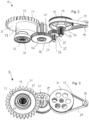
- the transmission 13 in the present embodiment has four gear stages, namely an input stage 17, an output stage 21 and two gear intermediate stages 25, 27. Typically, each stage serves to change the speed and the torque.
- the gear 35 is, as can be seen from Fig. 2 and 5 As can be seen, it is designed as a combination gear element with a gear 37, wherein the gear 37 functions as the pinion of the subsequent gear stage, namely the second intermediate gear stage 27.
- the gear 37 is in engagement with a gear 39, which functions as the wheel of the intermediate gear stage 27.
- the gear 39 is, as can be seen from Fig. 2 and 4 As can be seen, it is designed as a combination gear element with a gear 41 in one piece, wherein the gear 41 functions as the pinion of the subsequent gear stage, namely the output stage 21.
- the gear 41 is in engagement with a gear 43, which functions as the wheel and output element 23 of the output stage 21.
- the output stage 21 is also designed as a straight-toothed gear stage.
- the output element 23 of the output stage 21 is connected in a rotationally fixed manner to the output shaft 67. Due to the torque transmission to the output element 23, the output shaft 67 is set in rotation.
- the return element 59 comprises a heart-shaped cam disk, on which a pressure roller of the door drive 10 rolls, coupled to a mechanical energy storage device (also not shown).
- the mechanical energy storage device can in particular be a spring that is tensioned when the door is opened by means of the electric motor 11 and the gear 13. If the motor torque subsequently drops, for example due to a power failure, the spring relaxes, so that the pressure roller exerts pressure on the cam disk and rotates the output shaft 67 back against the opening direction. The door then moves automatically into its closed position.
- the gears 33, 35, 37, 39, 41, and 43 of the intermediate gear stages 25, 27 and the output stage 21 are sintered.
- the gears 41, 43 of the output stage 21 have a modulus m of approximately 1.5 mm to 3 mm to compensate for the somewhat lower strength of sintered steel compared to machined steel gears and to achieve the required service life.
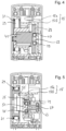
- the combination gear element on the side of the wheel 39 does not have a bearing journal, but rather a receiving bore 47 for a ball bearing 49 is provided, as Fig. 4
- the ball bearing 49 holds the wheel 39 in position with its outer ring, while a pin 53 of the housing part 15b engages in the ball bearing bore and receives the inner ring of the ball bearing 49. This allows the dimensions of the door drive 10 to be kept correspondingly compact.
- Fig. 5 shows, at the wheel 35 of the intermediate gear stage 25, which has a receiving bore 45 for a ball bearing 49.
- the ball bearing 49 holds the wheel 35 in position with its outer ring, while a pin 51 of the housing part 15a engages in the ball bearing bore and receives the inner ring of the ball bearing 49.
- Another ball bearing 49 is in fitting connection with its inner ring to an outer bearing pin 63 of the pinion 37. The outer ring of this ball bearing 49 is received in the housing part 15b.
- the pulley 31 has an annular recess 55.
- a bearing portion 57 of the housing part 15a extends into the recess 55 and accommodates a ball bearing 49 for the pinion 33 of the intermediate gear stage 25, in order to support the pinion 33 and the pulley 31 on the housing 15.
- Another ball bearing 49 is in fitting connection with its inner ring to an outer bearing pin 65 of the pinion 33.
- the illustrated embodiment corresponds overall to a door drive 10 that is inexpensive to manufacture due to the use of sintered gears, yet whose gears still exhibit sufficient strength. Furthermore, the door drive 10 is extremely compact and lightweight due to the use of the BLDC motor 11 and the design of the gears and housing 15. Finally, the belt drive stage, in particular, instead of a worm drive stage, ensures significantly higher efficiency.
- the output element 23 has three functional areas, namely the gear 43, the heart cam of the return element 59 and the internal toothing 61. Ideally, the three functional areas are manufactured in one sintering process, which significantly reduces costs.
- the output element 23 were turned and milled from solid material, the gear 43 would have to be milled, the return element 59 would have to be milled, and the internal toothing 61 would have to be broached. Due to the large chip volume, the output element would then be very expensive.
Landscapes
- Power-Operated Mechanisms For Wings (AREA)
Abstract
Ein Türantrieb, insbesondere ein Drehtürantrieb, weist einen Elektromotor zum Bereitstellen eines Motordrehmoments, eine Abtriebswelle, die geeignet ist, über einen Hebel oder eine Gestänge mit einer Zarge oder einem Flügel einer Tür gekoppelt zu werden, um ein Öffnungsdrehmoment bereitzustellen und die Tür aktiv von ihrer geschlossenen Stellung in ihre offene Stellung zu bewegen und/oder in ihrer offenen Stellung zu halten, und ein mehrstufiges Getriebe auf, welches den Elektromotor mit der Abtriebswelle koppelt. Das Getriebe weist eine Eingangsstufe mit einem Eingangselement zum Einspeisen des Motordrehmoments, eine Ausgangsstufe mit einem Ausgangselement, das drehfest mit der Abtriebswelle verbunden ist, und zumindest eine Zahnradzwischenstufe zwischen der Eingangsstufe und der Ausgangsstufe auf. Die Zahnradstufe an der Abtriebswelle hat einen Modul von 1,5 mm oder mehr und ist gesintert.
Description
- Die Erfindung betrifft einen Türantrieb, insbesondere einen Drehtürantrieb, mit einem Elektromotor, einer Abtriebswelle und einem mehrstufigen Getriebe. Außerdem betrifft die Erfindung ein Türsystem, insbesondere ein Drehtürsystem, das eine Tür mit einer Zarge und einem schwenkbar an der Zarge gelagerten Flügel und einen Türantrieb umfasst, wobei die Abtriebswelle des Türantriebs mit der Zarge oder dem Flügel gekoppelt ist.
- (Dreh-)Türantriebe sind dazu eingerichtet, eine Tür, insbesondere eine Drehtür wie etwa eine Schwenktür, aktiv von ihrer geschlossenen Stellung in ihre offene Stellung zu bringen und sie in ihrer offenen Stellung zu halten. Dazu sind derartige Türantriebe üblicherweise an einem feststehenden Bauteil wie etwa einer Zarge der Tür montiert. Ihre Abtriebswelle wird über ein Gestänge oder über einen Hebel mit einem Gleitstein und eine Gleitschiene mit einem Flügel der Tür verbunden. Aufgrund der Dimensionen der Zarge leitet sich die Anforderung ab, dass derartige Türantriebe möglichst kompakt auszuführen sind. Insbesondere soll der Türantrieb eine Höhe von ungefähr 70 mm normalerweise nicht überschreiten. Gleichzeitig sollen Türantriebe selbstredend möglichst kostengünstig sein.
- Es ist somit eine Aufgabe der vorliegenden Erfindung, einen Türantrieb bereitzustellen, der kompakt und günstig herzustellen ist.
- Diese Aufgabe wird durch den Gegenstand der unabhängigen Ansprüche gelöst. Vorteilhafte Weiterbildungen sind Gegenstand der abhängigen Ansprüche und ergeben sich aus der Beschreibung sowie aus den Zeichnungen.
- Der erfindungsgemäße Türantrieb kann insbesondere ein Drehtürantrieb sein und umfasst einen Elektromotor zum Bereitstellen eines Motordrehmoments, eine Abtriebswelle, die geeignet ist, über einen Hebel oder ein Gestänge mit einer Zarge oder einem Flügel einer Tür gekoppelt zu werden, um ein Öffnungsdrehmoment bereitzustellen und die Tür aktiv von ihrer geschlossenen Stellung in ihre offene Stellung zu bewegen und/oder in ihrer offenen Stellung zu halten, und ein mehrstufiges Getriebe, das den Elektromotor mit der Abtriebswelle koppelt. Das Getriebe weist eine Eingangsstufe mit einem Eingangselement zum Einspeisen des Motordrehmoments, eine Ausgangsstufe mit einem Ausgangselement, das drehfest mit der Abtriebswelle verbunden ist, und zumindest eine Zahnradzwischenstufe zwischen der Eingangsstufe und der Ausgangsstufe auf. Das Ausgangselement ist gesintert und weist einen Modul von 1,5 mm oder mehr auf.
- Bei dem Ausgangselement handelt es sich um die Zahnradstufe an der Abtriebswelle.
- Weitere Zahnradstufen können auch gesintert sein.
- Der Modul der Zahnradstufe an der Abtriebswelle (Modul des Ausgangselements) kann optional 1,75 mm bis 3,25 mm, vorzugsweise 2 mm bis 3 mm, insbesondere 2,5 mm betragen.
- Der Modul ist ein dem Fachmann geläufiges Maß für die Größe der Zähne eines Zahnrads und wird in Millimeter angegeben. Der Modul m entspricht dem Teilkreisdurchmesser d des Zahnrads geteilt durch die Anzahl z der Zähne des Zahnrads:

- Der Modul ist folglich eine wichtige Kenngröße zur Auslegung von Zahnrädern. Je nach Belastung, der die Zahnräder ausgesetzt werden, ist der Modul entsprechend auszuwählen, sodass die Zähne groß genug sind, um die Last aufzunehmen.
- Vorzugsweise werden das Zahnrad der Ausgangsstufe und die Zahnräder der Zahnradzwischenstufe(n) insbesondere aus Kostengründen gesintert, da hiermit Kosteneinsparungen von über 50 % gegenüber spanend hergestellten Zahnrädern möglich sind. Aufgrund des Moduls der Ausgangsstufe von 1,6 mm oder mehr ist es jedoch möglich, die üblicherweise geringere Festigkeit des Sintermaterials, etwa Sinterstahl, zu kompensieren, sodass die Zahnräder eine hohe Kostenersparnis erlauben und dennoch eine mit spanend hergestellten Zahnrädern gleichwertige Festigkeit aufweisen.
- Üblicherweise werden innerhalb einer Getriebestufe die Drehzahl und das Drehmoment geändert, was grundsätzlich aber nicht notwendigerweise der Fall sein muss. Getriebestufen können etwa als Zahnradstufen oder Riemenstufen ausgestaltet sein. Im Rahmen der vorliegenden Erfindung wird als Eingangsstufe die Getriebestufe bezeichnet, die das Eingangselement aufweist, über welches das Motordrehmoment eingespeist wird. Als Ausgangsstufe wird die Getriebestufe bezeichnet, die das Ausgangselement aufweist, mit welchem die Abtriebswelle drehfest und insbesondere koaxial verbunden ist. Die Zahnradzwischenstufe oder die Zahnradzwischenstufen verbindet bzw. verbinden die Eingangsstufe und die Ausgangsstufe miteinander.
- Die Abtriebswelle wird üblicherweise über einen Hebel oder ein Gestänge mit einer Zarge oder einem Flügel der Tür gekoppelt. Der Hebel kann etwa an seinem Ende einen Gleitstein aufweisen, der in einer an der Zarge oder dem Flügel befestigten Gleitschiene geführt ist. Das Gestänge kann insbesondere ein Scherengestänge sein, dessen Ende an der Zarge oder dem Flügel befestigt ist.
- In vorteilhafter Ausgestaltung ist der Elektromotor ein bürstenloser Gleichstrommotor, der auch als BLDC-Motor bezeichnet werden kann. BLDC-Motoren können relativ kurz bzw. flach sein, was sich positiv auf die Kompaktheit des Türantriebs auswirkt. Aufgrund seiner kompakten Ausführung kann der BLDC so verbaut werden, dass sich seine Ausgangswelle quer zum Getriebe erstreckt. Gleichzeitig sind BLDC-Motoren bei gleicher Leistung vergleichsweise leicht, insbesondere im Vergleich mit anderen Gleichstrommotoren.
- Der BLDC-Motor hat eine Nenndrehzahl von etwa 3700-5600 Umdrehungen pro Minute. Bei anderen Gleichstrommotoren liegen vergleichbare Nenndrehzahlen bei 1500-2500 Umdrehungen pro Minute. Um die gleiche Drehzahl an der Abtriebswelle zu erhalten, ist die gesamte Getriebeübersetzung etwa 500-600 statt 250-300.
- Vorzugsweise weist der Elektromotor eine drehfest mit dem Eingangselement verbundene Ausgangswelle zum Übertragen des Motordrehmoments auf das Eingangselement auf, wobei die Eingangsstufe ferner ein getriebenes Rad aufweist, das von dem Eingangselement angetrieben wird, und wobei die Achse der Ausgangswelle parallel zur Rotationsachse des getriebenen Rads verläuft. Insbesondere kann die Eingangsstufe als Riemenstufe ausgebildet sein. Diese Ausgestaltung ermöglicht einen höheren Wirkungsgrad des Getriebes im Vergleich zu Lösungen, bei denen die Achse der Ausgangswelle quer zur Rotationsachse des getriebenen Rads verläuft. Beispielsweise beträgt der Wirkungsgradverlust ungefähr 30 %, wenn die Eingangsstufe eine Schraubradstufe oder Schneckenstufe ist, wohingegen bei Stirnrad- oder Riemenstufen lediglich ungefähr 5 % Wirkungsgrad verloren wird.
- Das Getriebe kann wenigstens vier, insbesondere genau vier, Getriebestufen aufweisen. Bisher bekannte Türantriebe weisen üblicherweise drei Getriebestufen auf. Durch ein vierstufiges Getriebe können höhere Nenndrehzahlen des Elektromotors reduziert und ein höheres Moment an dem Ausgangselement erzielt werden. Die Verwendung des BLDC-Motors etwa kann dazu führen, dass die Nenndrehzahl verglichen mit anderen Gleichstrommotoren höher ist. Beispielsweise kann die Nenndrehzahl etwa im Bereich von 3.700 min-1 bis 5.600 min-1 liegen. Um dennoch eine vergleichbare Türöffnungszeit zu erreichen, ist eine höhere Übersetzung im Getriebe und somit die vierte Getriebestufe wünschenswert.
- Das Rad der Zahnradzwischenstufe oder die Räder der Zahnradzwischenstufen kann bzw. können als Kombinationsgetriebeelement mit dem Ritzel der jeweils nachfolgenden Getriebestufe einteilig ausgebildet sein. Derartige Kombinationsgetriebeelemente lassen sich gut mittels Sintern herstellen. Zudem kann bei der einteiligen Lösung auf zusätzliche Verbindungselemente wie Passfedern oder auf Fügevorgänge verzichtet werden, was außerdem vorteilhaft ist, um eine gute Festigkeit zu erzielen.
- Vorzugsweise weist oder weisen das Rad der Zahnradzwischenstufe oder die Räder der Zahnradzwischenstufen jeweils eine Aufnahmebohrung für ein Kugellager zum Lagern des jeweiligen Rads an einem Zapfen eines Gehäuses des Getriebes auf. Das Kugellager kann mit seinem Außenring in die Aufnahmebohrung eingepasst werden und das Rad an seiner Position halten. Anstelle eines herausstehenden Lagerzapfens wird auf eine Aufnahmebohrung zurückgegriffen, was sich durch Sintern gut herstellen lässt und zudem eine kompakte Bauform bewirkt.
- In bevorzugter Ausgestaltung weist die Eingangsstufe ein Riemenrad mit einer insbesondere ringförmigen Ausnehmung auf, wobei an dem Riemenrad ein Ritzel der nachfolgenden Zahnradzwischenstufe drehfest angeordnet ist, und wobei ein Lagerabschnitt eines Gehäuses des Getriebes in die Ausnehmung eintaucht und ein Kugellager für das Ritzel aufnimmt, um das Ritzel und das Riemenrad an dem Gehäuse zu lagern. Riemenrad und Ritzel können etwa durch einen Bolzen, eine Passfeder, eine Keilwelle oder durch ähnliche bekannte Maßnahmen drehfest miteinander verbunden sein.
- Vorzugsweise ist die Ausgangsstufe als Zahnradstufe ausgebildet. Dies trägt zu einem hohen Wirkungsgrad und einer guten und kostengünstigen Herstellbarkeit bei.
- Es kann ein mit dem Ausgangselement drehfest verbundenes, insbesondere damit einteilig ausgebildetes Rückstellelement vorgesehen sein, das ausgebildet ist, mit einem mechanischen Energiespeicher zusammenzuwirken, um bei Wegfall des Motordrehmoments eine selbsttätige Bewegung der Tür in die geschlossene Stellung herbeizuführen. Bei dem mechanischen Energiespeicher kann es sich insbesondere um eine Feder handeln, die beim Öffnen der Tür gespannt wird. Sofern das Motordrehmoment wegfällt, etwa im Falle eines Stromausfalls, bewirkt die gespannte Feder eine Schließbewegung der Tür. Vorzugsweise weist das Rückstellelement eine herzförmige Nockenscheibe auf, auf der eine mit dem mechanischen Energiespeicher gekoppelte Druckrolle des Türantriebs abrollt.
- In vorteilhafter Ausgestaltung umfasst die Abtriebswelle eine Innenverzahnung, insbesondere eine Innenkerbverzahnung, zum Eingreifen einer korrespondierenden Verzahnung eines Hebels oder eines Gestänges des Türantriebs. Somit kann auf zuverlässige Weise erreicht werden, dass die Drehung des Ausgangselements zu einer Öffnungsbewegung des Türflügels führt.
- Die Erfindung betrifft außerdem ein Türsystem, insbesondere ein Drehtürsystem, das eine Tür mit einer Zarge und einem schwenkbar an der Zarge gelagerten Flügel sowie den zuvor beschriebenen Türantrieb aufweist. Die Abtriebswelle ist dabei mit der Zarge oder dem Flügel gekoppelt.
- Die Erfindung wird nachfolgend lediglich beispielhaft anhand der schematischen Zeichnungen erläutert. Dabei zeigt
- Fig. 1
- eine perspektivische Ansicht eines Türantriebs gemäß einem Ausführungsbeispiel,
- Fig. 2
- eine perspektivische Ansicht des Getriebes des Türantriebs aus
Fig. 1 , - Fig. 3
- eine weitere perspektivische Ansicht des Getriebes des Türantriebs aus
Fig. 1 , - Fig. 4
- eine Schnittansicht des Türantriebs aus
Fig. 1 entsprechend der Schnittebene IV, - Fig. 5
- eine Schnittansicht des Türantriebs aus
Fig. 1 entsprechend der Schnittebene V und - Fig. 6
- eine Schnittansicht des Türantriebs aus
Fig. 1 entsprechend der Schnittebene VI. -
Fig. 1 zeigt eine perspektivische Ansicht eines Türantriebs 10, wobei das Gehäuse des Türantriebs 10 ausgeblendet ist. Der Türantrieb 10 weist einen Elektromotor 11 auf, der im vorliegenden Ausführungsbeispiel als bürstenloser Gleichstrommotor, auch als BLDC-Motor bezeichnet, ausgebildet ist. - Vorzugsweise wird ein BLDC-Außenläufermotor verwendet, dessen Motorachse parallel zur Achse der Abtriebsstufe angeordnet ist. Der Außenläufer ist mit Ferritmagneten bestückt im Gegensatz zu den Innenläufern, die oft mit teuren und stärkeren Neodymmagneten gebaut werden. Der größere Wirkradius des Außenläufers kompensiert teilweise die geringere Magnetkraft.
- Außerdem weist der Türantrieb 10 eine Abtriebswelle 67 mit einer Innenverzahnung 61, nämlich einer Innenkerbverzahnung, auf. Die Innenverzahnung 61 dient zum Eingreifen eines nicht dargestellten Hebels oder Gestänges mit einer korrespondierenden Außenverzahnung. Die über den Hebel oder das Gestänge mit einer Zarge oder einem Flügel einer Tür gekoppelte Abtriebswelle 67 stellt ein Öffnungsdrehmoment bereit, um die Tür aktiv von ihrer geschlossenen Stellung in ihre offene Stellung zu bewegen und/oder in ihrer offenen Stellung zu halten.
- Der Türantrieb 10 weist ferner ein Getriebe 13 auf. Das Getriebe 13 ist zwischen den Elektromotor 11 und die Abtriebswelle 67 geschaltet, sodass ein von dem Elektromotor 11 in das Getriebe 13 eingespeistes Motordrehmoment über die Getriebestufen zur Rotation der Abtriebswelle 67 und damit des Hebels oder des Gestänges führt. Der Elektromotor 11, das Getriebe 13 und die Abtriebswelle 67 sind in einem Gehäuse 15 aufgenommen, welches aus zwei Gehäuseteilen 15a, 15b zusammengesetzt ist (vgl.
Fig. 4 bis 6 ), die miteinander mittels Verbindungselementen, etwa Schrauben, Stiften oder Bolzen, verbunden sind. - Wie
Fig. 2 und 3 zeigen, weist das Getriebe 13 im vorliegenden Ausführungsbeispiel vier Getriebestufen auf, nämlich eine Eingangsstufe 17, eine Ausgangsstufe 21 und zwei Zahnradzwischenstufen 25, 27. Üblicherweise dient jede Stufe dazu, die Drehzahl und das Drehmoment zu ändern. - Die Eingangsstufe 17 ist als Riemenstufe ausgebildet und umfasst ein getriebenes Riemenrad 31 und ein Eingangselement 19 in Form eines kleineren, treibenden Riemenrads, das mit einer nicht gezeigten Ausgangswelle des Elektromotors 11 in Eingriff gebracht werden kann, um das Motordrehmoment auf das Eingangselement 19 zu übertragen. Ein Zahnriemen 29 ist mit dem Eingangselement 19 und dem Riemenrad 31 im Eingriff, sodass das Riemenrad 31 von dem Eingangselement 19 mittels des Riemens 29 angetrieben wird.
- Das Riemenrad 31 ist, wie aus
Fig. 2 und6 ersichtlich, drehfest mit einem Zahnrad 33 verbunden, das mit einem weiteren Zahnrad 35 im Eingriff ist. Das Zahnrad 33 und das Zahnrad 35 bilden gemeinsam die erste Zahnradzwischenstufe 25, wobei das Zahnrad 33 als Ritzel und das Zahnrad 35 als Rad fungiert. Vorliegend ist die Zahnradzwischenstufe 25 als geradverzahnte Zahnradstufe ausgebildet. In anderen Ausführungsformen ist auch denkbar, dass die Zahnradzwischenstufe 25 schrägverzahnt ist. - Das Zahnrad 35 ist, wie aus
Fig. 2 und5 ersichtlich ist, als Kombinationsgetriebeelement mit einem Zahnrad 37 einteilig ausgebildet, wobei das Zahnrad 37 als Ritzel der nachfolgenden Getriebestufe, nämlich der zweiten Zahnradzwischenstufe 27, fungiert. Das Zahnrad 37 ist im Eingriff mit einem Zahnrad 39, das als Rad der Zahnradzwischenstufe 27 fungiert. - Das Zahnrad 39 ist, wie aus
Fig. 2 und4 ersichtlich ist, als Kombinationsgetriebeelement mit einem Zahnrad 41 einteilig ausgebildet, wobei das Zahnrad 41 als Ritzel der nachfolgenden Getriebestufe, nämlich der Ausgangsstufe 21, fungiert. Das Zahnrad 41 ist im Eingriff mit einem Zahnrad 43, das als Rad und Ausgangselement 23 der Ausgangsstufe 21 fungiert. Auch die Ausgangsstufe 21 ist als geradverzahnte Zahnradstufe ausgebildet. - Das Ausgangselement 23 der Ausgangsstufe 21 ist drehfest mit der Abtriebswelle 67 verbunden. Aufgrund der Drehmomentübertragung auf das Ausgangselement 23 wird damit die Abtriebswelle 67 in Rotation versetzt.
- Einteilig mit dem Ausgangselement 23 ausgebildet ist ein in
Fig. 2 gezeigtes Rückstellelement 59. Das Rückstellelement 59 umfasst eine herzförmige Nockenscheibe, auf der eine mit einem nicht dargestellten mechanischen Energiespeicher gekoppelte, ebenfalls nicht dargestellte Druckrolle des Türantriebs 10 abrollt. Der mechanische Energiespeicher kann insbesondere eine Feder sein, die beim Öffnen der Tür mittels des Elektromotors 11 und des Getriebes 13 gespannt wird. Fällt das Motordrehmoment anschließend weg, etwa wegen eines Stromausfalls, entspannt sich die Feder, sodass die Druckrolle auf die Nockenscheibe Druck ausübt und die Abtriebswelle 67 entgegen der Öffnungsrichtung zurückdreht. Dabei bewegt sich die Tür selbsttätig in ihre geschlossene Stellung. - Die Zahnräder 33, 35, 37, 39, 41, 43 der Zahnradzwischenstufen 25, 27 und der Ausgangsstufe 21 sind gesintert. Die Zahnräder 41, 43 der Ausgangsstufe 21 weisen im vorliegenden Ausführungsbeispiel einen Modul m von ungefähr 1,5 mm bis 3 mm auf, um die etwas geringere Festigkeit des Sinterstahls gegenüber spanend hergestellten Stahlzahnrädern zu kompensieren und die erforderliche Lebensdauer zu erreichen.
- Um das Rad 39 der Zahnradzwischenstufe 27 mit dem Ritzel 41 der Ausgangsstufe 21 als ein Teil sintern zu können, ist bei dem Kombinationsgetriebeelement auf Seite des Rads 39 kein Lagerzapfen, sondern eine Aufnahmebohrung 47 für ein Kugellager 49 vorgesehen, wie
Fig. 4 zeigt. Dies erleichtert auch die Herstellung mittels Sintern. Das Kugellager 49 hält das Rad 39 mit seinem Außenring in Position, während ein Zapfen 53 des Gehäuseteils 15b in die Kugellagerbohrung greift und den Innenring des Kugellagers 49 aufnimmt. Damit kann die Dimension des Türantriebs 10 entsprechend kompakt gehalten werden. Ähnlich verhält es sich, wieFig. 5 zeigt, bei dem Rad 35 der Zahnradzwischenstufe 25, das eine Aufnahmebohrung 45 für ein Kugellager 49 aufweist. Das Kugellager 49 hält das Rad 35 mit seinem Außenring in Position, während ein Zapfen 51 des Gehäuseteils 15a in die Kugellagerbohrung greift und den Innenring des Kugellagers 49 aufnimmt. Ein weiteres Kugellager 49 ist mit seinem Innenring in Passverbindung mit einem äußeren Lagerzapfen 63 des Ritzels 37. Der Außenring dieses Kugellagers 49 ist in dem Gehäuseteil 15b aufgenommen. - Wie
Fig. 2 ,5 und6 zeigen, weist das Riemenrad 31 eine ringförmige Ausnehmung 55 auf. Ein Lagerabschnitt 57 des Gehäuseteils 15a taucht in die Ausnehmung 55 ein und nimmt ein Kugellager 49 für das Ritzel 33 der Zahnradzwischenstufe 25 auf, um das Ritzel 33 und das Riemenrad 31 an dem Gehäuse 15 zu lagern. Ein weiteres Kugellager 49 ist mit seinem Innenring in Passverbindung mit einem äußeren Lagerzapfen 65 des Ritzels 33. - Das gezeigte Ausführungsbeispiel entspricht insgesamt einem Türantrieb 10, der aufgrund der Verwendung von Sinterrädern günstig herzustellen ist, dessen Zahnräder dennoch auch eine hinreichende Festigkeit aufweisen. Der Türantrieb 10 ist ferner aufgrund der Verwendung des BLDC-Motors 11 und der Ausgestaltung der Zahnräder sowie des Gehäuses 15 äußerst kompakt und leicht. Schließlich gewährleistet insbesondere die Riemenstufe anstelle einer Schneckenstufe einen deutlich höheren Wirkungsgrad.
- Das Ausgangselement 23 hat außer den zwei Lagerstellen drei Funktionsbereiche und zwar das Zahnrad 43, die Herzkurve des Rückstellelements 59 und die Innenverzahnung 61. Idealerweise werden die drei Funktionsbereiche in einem Sintervorgang hergestellt, was die Kosten deutlich senkt.
- Würde das Ausgangselement 23 spanend aus dem Vollen gedreht und gefräst werden, müsste das Zahnrad 43 gefräst, das Rückstellelement 59 gefräst und die Innenverzahnung 61 geräumt werden. Aufgrund des großen Spanvolumens wäre das Ausgangselement dann sehr teuer.
- Selbst wenn bei dem gesinterten Ausgangselement 23 das Rückstellelement 59 gefräst und die Innenverzahnung 61 geräumt werden müsste, wären Spanvolumen und Kosten deutlich kleiner als bei einer spanenden Herstellung aus dem Vollen.
-
- 10
- Türantrieb
- 11
- Elektromotor
- 13
- Getriebe
- 15
- Gehäuse
- 15a
- Gehäuseteil
- 15b
- Gehäuseteil
- 17
- Eingangsstufe
- 19
- Eingangselement
- 21
- Ausgangsstufe
- 23
- Ausgangselement
- 25
- Zahnradzwischenstufe
- 27
- Zahnradzwischenstufe
- 29
- Riemen
- 31
- Riemenrad
- 33
- Zahnrad
- 35
- Zahnrad
- 37
- Zahnrad
- 39
- Zahnrad
- 41
- Zahnrad
- 43
- Zahnrad
- 45
- Aufnahmebohrung
- 47
- Aufnahmebohrung
- 49
- Kugellager
- 51
- Zapfen
- 53
- Zapfen
- 55
- Ausnehmung
- 57
- Lagerabschnitt
- 59
- Rückstellelement
- 61
- Innenverzahnung
- 63
- Lagerzapfen
- 65
- Lagerzapfen
- 67
- Abtriebswelle
Claims (14)
- Türantrieb (10), insbesondere Drehtürantrieb, der einen Elektromotor (11) zum Bereitstellen eines Motordrehmoments, eine Abtriebswelle (67), die geeignet ist, über einen Hebel oder ein Gestänge mit einer Zarge oder einem Flügel einer Tür gekoppelt zu werden, um ein Öffnungsdrehmoment bereitzustellen und die Tür aktiv von ihrer geschlossenen Stellung in ihre offene Stellung zu bewegen und/oder in ihrer offenen Stellung zu halten, undein mehrstufiges Getriebe (13) aufweist, das den Elektromotor (11) mit der Abtriebswelle (67) koppelt,wobei das Getriebe (13) eine Eingangsstufe (17) mit einem Eingangselement (19) zum Einspeisen des Motordrehmoments, eine Ausgangsstufe (21) mit einem Ausgangselement (23), das drehfest mit der Abtriebswelle (67) verbunden ist, und zumindest eine Zahnradzwischenstufe (25, 27) zwischen der Eingangsstufe (17) und der Ausgangsstufe (21) aufweist, und wobei das Ausgangselement (23) gesintert ist und einen Modul von 1,5 mm oder mehr aufweist.
- Türantrieb (10) nach Anspruch 1,
dadurch gekennzeichnet, dass das Ausgangselement (23) mit dem Zahnrad (43), dem Rückstellelement (59) und der Innenverzahnung (61) fertig gesintert ist, oder dass das Rückstellelement (59) gefräst und die Innenverzahnung (61) geräumt ist. - Türantrieb (10) nach Anspruch 1 oder 2,
dadurch gekennzeichnet, dass der Modul des Ausgangselements (23) 1,5 mm bis 3,25 mm, vorzugsweise 2 mm bis 3 mm, insbesondere 2,5 mm, beträgt. - Türantrieb (10) nach einem der vorstehenden Ansprüche,
dadurch gekennzeichnet, dass der Elektromotor (11) ein bürstenloser Gleichstrommotor, vorzugsweise ein Außenläufermotor, dessen Antriebswelle parallel zu der Abtriebswelle (67) ist, ist. - Türantrieb (10) nach einem der vorstehenden Ansprüche,
dadurch gekennzeichnet, dass die Eingangsstufe (17) als Zahnriemenstufe ausgebildet ist. - Türantrieb (10) nach einem der vorstehenden Ansprüche,
dadurch gekennzeichnet, dass das Getriebe (13) wenigstens vier, insbesondere genau vier, Getriebestufen (17, 21, 25, 27) aufweist. - Türantrieb (10) nach einem der vorstehenden Ansprüche,
dadurch gekennzeichnet, dass das Rad (35, 39) der Zahnradzwischenstufe (25, 27) oder die Räder (35, 39) der Zahnradzwischenstufen (25, 27) als Kombinationsgetriebeelement mit dem Ritzel (37, 41) der jeweils nachfolgenden Getriebestufe (21, 27) einteilig ausgebildet ist oder sind. - Türantrieb (10) nach einem der vorstehenden Ansprüche,
dadurch gekennzeichnet, dass das Rad (35, 39) der Zahnradzwischenstufe (25, 27) oder die Räder (35, 39) der Zahnradzwischenstufen (25, 27) jeweils eine Aufnahmebohrung (45, 47) für ein Kugellager (49) zum Lagern des jeweiligen Rads (35, 39) an einem Zapfen (51, 53) eines Gehäuses (15) des Getriebes (13) aufweisen. - Türantrieb (10) nach einem der vorstehenden Ansprüche,
dadurch gekennzeichnet, dass die Eingangsstufe (17) ein Riemenrad (31) mit einer insbesondere ringförmigen Ausnehmung (55) aufweist, wobei an dem Riemenrad (31) ein Ritzel (33) der nachfolgenden Zahnradzwischenstufe (25) drehfest angeordnet ist, und wobei ein Lagerabschnitt (57) eines Gehäuses (15) des Getriebes (13) in die Ausnehmung (55) eintaucht und ein Kugellager (49) für das Ritzel (33) aufnimmt, um das Ritzel (33) und das Riemenrad (31) an dem Gehäuse (15) zu lagern. - Türantrieb (10) nach einem der vorstehenden Ansprüche,
dadurch gekennzeichnet, dass die Ausgangsstufe (21) als Zahnradstufe ausgebildet ist. - Türantrieb (10) nach einem der vorstehenden Ansprüche,
dadurch gekennzeichnet, dass ein mit dem Ausgangselement (23) drehfest verbundenes, insbesondere damit einteilig ausgebildetes Rückstellelement (59) vorgesehen ist, das ausgebildet ist, mit einem mechanischen Energiespeicher zusammenzuwirken, um bei Wegfall des Motordrehmoments eine selbsttätige Bewegung der Tür in die geschlossene Stellung herbeizuführen. - Türantrieb (10) nach Anspruch 11,
dadurch gekennzeichnet, dass das Rückstellelement (59) eine herzförmige Nockenscheibe aufweist, auf der eine mit dem mechanischen Energiespeicher gekoppelte Druckrolle des Türantriebs (10) abrollt. - Türantrieb (10) nach einem der vorstehenden Ansprüche,
dadurch gekennzeichnet, dass die Abtriebswelle (67) eine Innenverzahnung (61), insbesondere eine Innenkerbverzahnung, zum Eingreifen einer korrespondierenden Verzahnung eines Hebels oder eines Gestänges des Türantriebs (10) aufweist. - Türsystem, insbesondere Drehtürsystem, umfassend eine Tür mit einer Zarge und einem schwenkbar an der Zarge gelagerten Flügel und einen Türantrieb (10) nach einem der vorstehenden Ansprüche, wobei die Abtriebswelle (67) mit der Zarge oder dem Flügel gekoppelt ist.
Applications Claiming Priority (1)
| Application Number | Priority Date | Filing Date | Title |
|---|---|---|---|
| DE102023208572.0A DE102023208572B3 (de) | 2023-09-06 | 2023-09-06 | Türantrieb und Türsystem |
Publications (1)
| Publication Number | Publication Date |
|---|---|
| EP4520905A1 true EP4520905A1 (de) | 2025-03-12 |
Family
ID=92295517
Family Applications (1)
| Application Number | Title | Priority Date | Filing Date |
|---|---|---|---|
| EP24193563.4A Pending EP4520905A1 (de) | 2023-09-06 | 2024-08-08 | Türantrieb und türsystem |
Country Status (2)
| Country | Link |
|---|---|
| EP (1) | EP4520905A1 (de) |
| DE (1) | DE102023208572B3 (de) |
Citations (5)
| Publication number | Priority date | Publication date | Assignee | Title |
|---|---|---|---|---|
| DE102015202852B3 (de) * | 2015-02-17 | 2016-03-24 | Geze Gmbh | Türantrieb |
| DE102016106702B3 (de) * | 2016-04-12 | 2017-08-10 | Hörmann KG Antriebstechnik | Getriebemotor für einen Gebäudeabschlussantrieb sowie damit versehener Gebäudeabschlussantrieb |
| DE102019200656A1 (de) * | 2019-01-18 | 2020-07-23 | Geze Gmbh | Antrieb für eine karusselldrehtür |
| EP3757338A1 (de) * | 2019-06-25 | 2020-12-30 | GEZE GmbH | Vorrichtung und verfahren zur steuerung der bewegung einer tür |
| DE102020125098A1 (de) * | 2020-09-25 | 2022-03-31 | Dormakaba Deutschland Gmbh | Verfahren zum Verschwenken eines Flügels mit einer Antriebseinrichtung und Antriebseinrichtung zum Verschwenken eines Flügels |
Family Cites Families (2)
| Publication number | Priority date | Publication date | Assignee | Title |
|---|---|---|---|---|
| IT201900006733A1 (it) * | 2019-05-10 | 2020-11-10 | Faac Spa | Attuatore motorizzato e barriera mobile provvista di tale attuatore, particolarmente adatto per azionamenti ausiliari o di emergenza. |
| AT526473A1 (de) * | 2022-09-09 | 2024-03-15 | Blum Gmbh Julius | Möbelantrieb zum Antreiben eines bewegbaren Möbelteils |
-
2023
- 2023-09-06 DE DE102023208572.0A patent/DE102023208572B3/de active Active
-
2024
- 2024-08-08 EP EP24193563.4A patent/EP4520905A1/de active Pending
Patent Citations (5)
| Publication number | Priority date | Publication date | Assignee | Title |
|---|---|---|---|---|
| DE102015202852B3 (de) * | 2015-02-17 | 2016-03-24 | Geze Gmbh | Türantrieb |
| DE102016106702B3 (de) * | 2016-04-12 | 2017-08-10 | Hörmann KG Antriebstechnik | Getriebemotor für einen Gebäudeabschlussantrieb sowie damit versehener Gebäudeabschlussantrieb |
| DE102019200656A1 (de) * | 2019-01-18 | 2020-07-23 | Geze Gmbh | Antrieb für eine karusselldrehtür |
| EP3757338A1 (de) * | 2019-06-25 | 2020-12-30 | GEZE GmbH | Vorrichtung und verfahren zur steuerung der bewegung einer tür |
| DE102020125098A1 (de) * | 2020-09-25 | 2022-03-31 | Dormakaba Deutschland Gmbh | Verfahren zum Verschwenken eines Flügels mit einer Antriebseinrichtung und Antriebseinrichtung zum Verschwenken eines Flügels |
Also Published As
| Publication number | Publication date |
|---|---|
| DE102023208572B3 (de) | 2025-01-23 |
Similar Documents
| Publication | Publication Date | Title |
|---|---|---|
| EP2933415B1 (de) | Türantrieb | |
| EP2423022B1 (de) | Verstellantrieb mit Notbetätigung | |
| EP2737612B1 (de) | Radnahe antriebseinheit für ein kraftfahrzeug | |
| EP1110011B1 (de) | Mehrstufiges stirnradgetriebe | |
| EP1863998A1 (de) | Getriebe-antriebseinheit mit einer lastdrehmomentsperre | |
| EP4399383A1 (de) | Kraftfahrzeug-schloss insbesondere kraftfahrzeug-türschloss | |
| WO2003100296A1 (de) | Standard-antrieb, baureihe mit zwischenflansch | |
| DE102010038597A1 (de) | Zentrierung eines Planetengetriebes | |
| EP4314459B1 (de) | Antrieb für eine tür oder ein fenster | |
| DE19736572A1 (de) | Getriebe mit Leistungsverzweigung, insbesondere für einen Hubschrauber-Rotor-Antrieb | |
| DE10256752B3 (de) | Standard-Getriebe und Bausatz | |
| DE102019200656A1 (de) | Antrieb für eine karusselldrehtür | |
| DE102023208572B3 (de) | Türantrieb und Türsystem | |
| EP3688339A1 (de) | Getriebeanordnung für eine verstelleinheit | |
| EP1899628B1 (de) | Getriebe-antriebseinheit | |
| DE102019127953B4 (de) | Lenkgetriebe für ein elektromechanisches Lenksystem für ein Fahrzeug und elektromechanisches Lenksystem für ein Fahrzeug | |
| EP1765621B1 (de) | Türmodel für eine fahrzeugtür | |
| DE102024107399B3 (de) | Antrieb für eine Tür oder ein Fenster mit verbessertem Wirkungsgrad | |
| DE102005062999B4 (de) | Elektromotorischer Möbelantrieb | |
| DE102015202852B3 (de) | Türantrieb | |
| EP1075931B1 (de) | Exzenterpresse | |
| EP1800850A2 (de) | Antriebseinrichtung für eine Umformmaschine, insbesondere Presseantrieb, sowie Umformmaschine | |
| DE102015202832B3 (de) | Türantrieb | |
| WO2005061832A2 (de) | Fensterhebersystem mit wahlweise einsetzbarer manueller oder motorischer antriebseinrichtung | |
| WO2014139693A1 (de) | Getriebe-antriebseinheit und komfortantrieb mit einer getriebe-antriebseinheit |
Legal Events
| Date | Code | Title | Description |
|---|---|---|---|
| PUAI | Public reference made under article 153(3) epc to a published international application that has entered the european phase |
Free format text: ORIGINAL CODE: 0009012 |
|
| STAA | Information on the status of an ep patent application or granted ep patent |
Free format text: STATUS: THE APPLICATION HAS BEEN PUBLISHED |
|
| AK | Designated contracting states |
Kind code of ref document: A1 Designated state(s): AL AT BE BG CH CY CZ DE DK EE ES FI FR GB GR HR HU IE IS IT LI LT LU LV MC ME MK MT NL NO PL PT RO RS SE SI SK SM TR |
|
| STAA | Information on the status of an ep patent application or granted ep patent |
Free format text: STATUS: REQUEST FOR EXAMINATION WAS MADE |
|
| 17P | Request for examination filed |
Effective date: 20250725 |