EP4520737A1 - Vorrichtung und verfahren zur kohlenstoffsequestrierung von stahlschlacke - Google Patents
Vorrichtung und verfahren zur kohlenstoffsequestrierung von stahlschlacke Download PDFInfo
- Publication number
- EP4520737A1 EP4520737A1 EP23915185.5A EP23915185A EP4520737A1 EP 4520737 A1 EP4520737 A1 EP 4520737A1 EP 23915185 A EP23915185 A EP 23915185A EP 4520737 A1 EP4520737 A1 EP 4520737A1
- Authority
- EP
- European Patent Office
- Prior art keywords
- steel slag
- industrial waste
- carbon fixation
- waste gas
- ranges
- Prior art date
- Legal status (The legal status is an assumption and is not a legal conclusion. Google has not performed a legal analysis and makes no representation as to the accuracy of the status listed.)
- Pending
Links
Images
Classifications
-
- B—PERFORMING OPERATIONS; TRANSPORTING
- B01—PHYSICAL OR CHEMICAL PROCESSES OR APPARATUS IN GENERAL
- B01D—SEPARATION
- B01D53/00—Separation of gases or vapours; Recovering vapours of volatile solvents from gases; Chemical or biological purification of waste gases, e.g. engine exhaust gases, smoke, fumes, flue gases, aerosols
- B01D53/34—Chemical or biological purification of waste gases
- B01D53/74—General processes for purification of waste gases; Apparatus or devices specially adapted therefor
- B01D53/81—Solid phase processes
- B01D53/83—Solid phase processes with moving reactants
-
- B—PERFORMING OPERATIONS; TRANSPORTING
- B01—PHYSICAL OR CHEMICAL PROCESSES OR APPARATUS IN GENERAL
- B01D—SEPARATION
- B01D53/00—Separation of gases or vapours; Recovering vapours of volatile solvents from gases; Chemical or biological purification of waste gases, e.g. engine exhaust gases, smoke, fumes, flue gases, aerosols
- B01D53/34—Chemical or biological purification of waste gases
- B01D53/46—Removing components of defined structure
- B01D53/62—Carbon oxides
-
- B—PERFORMING OPERATIONS; TRANSPORTING
- B01—PHYSICAL OR CHEMICAL PROCESSES OR APPARATUS IN GENERAL
- B01D—SEPARATION
- B01D53/00—Separation of gases or vapours; Recovering vapours of volatile solvents from gases; Chemical or biological purification of waste gases, e.g. engine exhaust gases, smoke, fumes, flue gases, aerosols
- B01D53/34—Chemical or biological purification of waste gases
- B01D53/74—General processes for purification of waste gases; Apparatus or devices specially adapted therefor
- B01D53/81—Solid phase processes
-
- C—CHEMISTRY; METALLURGY
- C04—CEMENTS; CONCRETE; ARTIFICIAL STONE; CERAMICS; REFRACTORIES
- C04B—LIME, MAGNESIA; SLAG; CEMENTS; COMPOSITIONS THEREOF, e.g. MORTARS, CONCRETE OR LIKE BUILDING MATERIALS; ARTIFICIAL STONE; CERAMICS; REFRACTORIES; TREATMENT OF NATURAL STONE
- C04B20/00—Use of materials as fillers for mortars, concrete or artificial stone according to more than one of groups C04B14/00 - C04B18/00 and characterised by shape or grain distribution; Treatment of materials according to more than one of the groups C04B14/00 - C04B18/00 specially adapted to enhance their filling properties in mortars, concrete or artificial stone; Expanding or defibrillating materials
- C04B20/02—Treatment
- C04B20/023—Chemical treatment
- C04B20/0232—Chemical treatment with carbon dioxide
-
- C—CHEMISTRY; METALLURGY
- C04—CEMENTS; CONCRETE; ARTIFICIAL STONE; CERAMICS; REFRACTORIES
- C04B—LIME, MAGNESIA; SLAG; CEMENTS; COMPOSITIONS THEREOF, e.g. MORTARS, CONCRETE OR LIKE BUILDING MATERIALS; ARTIFICIAL STONE; CERAMICS; REFRACTORIES; TREATMENT OF NATURAL STONE
- C04B5/00—Treatment of metallurgical slag ; Artificial stone from molten metallurgical slag
- C04B5/06—Ingredients, other than water, added to the molten slag or to the granulating medium or before remelting; Treatment with gases or gas generating compounds, e.g. to obtain porous slag
-
- C—CHEMISTRY; METALLURGY
- C21—METALLURGY OF IRON
- C21B—MANUFACTURE OF IRON OR STEEL
- C21B3/00—General features in the manufacture of pig-iron
- C21B3/04—Recovery of by-products, e.g. slag
-
- C—CHEMISTRY; METALLURGY
- C22—METALLURGY; FERROUS OR NON-FERROUS ALLOYS; TREATMENT OF ALLOYS OR NON-FERROUS METALS
- C22B—PRODUCTION AND REFINING OF METALS; PRETREATMENT OF RAW MATERIALS
- C22B7/00—Working up raw materials other than ores, e.g. scrap, to produce non-ferrous metals and compounds thereof; Methods of a general interest or applied to the winning of more than two metals
- C22B7/04—Working-up slag
-
- B—PERFORMING OPERATIONS; TRANSPORTING
- B01—PHYSICAL OR CHEMICAL PROCESSES OR APPARATUS IN GENERAL
- B01D—SEPARATION
- B01D2251/00—Reactants
- B01D2251/40—Alkaline earth metal or magnesium compounds
- B01D2251/404—Alkaline earth metal or magnesium compounds of calcium
-
- B—PERFORMING OPERATIONS; TRANSPORTING
- B01—PHYSICAL OR CHEMICAL PROCESSES OR APPARATUS IN GENERAL
- B01D—SEPARATION
- B01D2251/00—Reactants
- B01D2251/60—Inorganic bases or salts
- B01D2251/602—Oxides
-
- B—PERFORMING OPERATIONS; TRANSPORTING
- B01—PHYSICAL OR CHEMICAL PROCESSES OR APPARATUS IN GENERAL
- B01D—SEPARATION
- B01D2253/00—Adsorbents used in seperation treatment of gases and vapours
- B01D2253/30—Physical properties of adsorbents
- B01D2253/302—Dimensions
- B01D2253/304—Linear dimensions, e.g. particle shape, diameter
-
- B—PERFORMING OPERATIONS; TRANSPORTING
- B01—PHYSICAL OR CHEMICAL PROCESSES OR APPARATUS IN GENERAL
- B01D—SEPARATION
- B01D2257/00—Components to be removed
- B01D2257/30—Sulfur compounds
- B01D2257/302—Sulfur oxides
-
- B—PERFORMING OPERATIONS; TRANSPORTING
- B01—PHYSICAL OR CHEMICAL PROCESSES OR APPARATUS IN GENERAL
- B01D—SEPARATION
- B01D2257/00—Components to be removed
- B01D2257/50—Carbon oxides
- B01D2257/504—Carbon dioxide
-
- B—PERFORMING OPERATIONS; TRANSPORTING
- B01—PHYSICAL OR CHEMICAL PROCESSES OR APPARATUS IN GENERAL
- B01D—SEPARATION
- B01D2258/00—Sources of waste gases
- B01D2258/02—Other waste gases
- B01D2258/0283—Flue gases
-
- B—PERFORMING OPERATIONS; TRANSPORTING
- B01—PHYSICAL OR CHEMICAL PROCESSES OR APPARATUS IN GENERAL
- B01D—SEPARATION
- B01D53/00—Separation of gases or vapours; Recovering vapours of volatile solvents from gases; Chemical or biological purification of waste gases, e.g. engine exhaust gases, smoke, fumes, flue gases, aerosols
- B01D53/34—Chemical or biological purification of waste gases
- B01D53/46—Removing components of defined structure
- B01D53/48—Sulfur compounds
- B01D53/50—Sulfur oxides
- B01D53/508—Sulfur oxides by treating the gases with solids
-
- C—CHEMISTRY; METALLURGY
- C04—CEMENTS; CONCRETE; ARTIFICIAL STONE; CERAMICS; REFRACTORIES
- C04B—LIME, MAGNESIA; SLAG; CEMENTS; COMPOSITIONS THEREOF, e.g. MORTARS, CONCRETE OR LIKE BUILDING MATERIALS; ARTIFICIAL STONE; CERAMICS; REFRACTORIES; TREATMENT OF NATURAL STONE
- C04B2111/00—Mortars, concrete or artificial stone or mixtures to prepare them, characterised by specific function, property or use
- C04B2111/00017—Aspects relating to the protection of the environment
- C04B2111/00019—Carbon dioxide sequestration
-
- C—CHEMISTRY; METALLURGY
- C21—METALLURGY OF IRON
- C21B—MANUFACTURE OF IRON OR STEEL
- C21B2400/00—Treatment of slags originating from iron or steel processes
- C21B2400/02—Physical or chemical treatment of slags
-
- Y—GENERAL TAGGING OF NEW TECHNOLOGICAL DEVELOPMENTS; GENERAL TAGGING OF CROSS-SECTIONAL TECHNOLOGIES SPANNING OVER SEVERAL SECTIONS OF THE IPC; TECHNICAL SUBJECTS COVERED BY FORMER USPC CROSS-REFERENCE ART COLLECTIONS [XRACs] AND DIGESTS
- Y02—TECHNOLOGIES OR APPLICATIONS FOR MITIGATION OR ADAPTATION AGAINST CLIMATE CHANGE
- Y02C—CAPTURE, STORAGE, SEQUESTRATION OR DISPOSAL OF GREENHOUSE GASES [GHG]
- Y02C20/00—Capture or disposal of greenhouse gases
- Y02C20/40—Capture or disposal of greenhouse gases of CO2
Definitions
- the present application relates to the field of resource utilization of industrial waste, in particular to an apparatus and method for steel slag carbon fixation.
- Steel slag is one of major by-products produced in a steel production process, a large amount of steel slag is produced annually, but 60% of the steel slag is not effectively utilized, so resource utilization of the steel slag is of great significance.
- Main factors that limit the resource utilization of the steel slag are that the steel slag contains a large amount of unstable free calcium oxide, on the one hand, a content of the free calcium oxide in the steel slag is high, so the steel slag is prone to expansion pulverization and soundness is poor, then a series of quality issues such as pavement expansion and cracking may occur when the steel slag is applied to road engineering, and on the other hand, a reduction effect of the free calcium oxide in the steel slag is unstable and thus is difficult to remain a low level.
- calcium carbonate is formed by a reaction of carbon dioxide and the free calcium oxide in the steel slag, which may not only effectively improve the stability of the steel slag and widen the application field of the steel slag, but also reduce emissions of carbon dioxide, thereby achieving double benefits in the aspects of carbon dioxide emission reduction and solid waste resource recovery.
- a method for CO 2 fixation and digestion of the free calcium oxide in steel slag powder is disclosed in the prior art, which mainly lies in that soaked steel slag and waste heat smoke containing carbon dioxide undergo a stable reaction in a pulverizer, so as to achieve fixation of carbon dioxide and digestion of the free calcium oxide, however, by means of this method, excessive water remains on a surface of the steel slag to form a water film due to steel slag soaking, which affects contact between carbon dioxide and free calcium oxide in the steel slag, meanwhile, soaking of the steel slag causes dissolving out of other element calcium besides the free calcium oxide, waste water produced after soaking of the steel slag needs to be retreated, so cost of resource utilization increases, and in addition, loss of the element calcium causes reduction of a carbon fixation rate of the steel slag.
- a technical problem to be solved by the present application is to overcome the defects that in the prior art, a water film is formed due to steel slag soaking, then contact between carbon dioxide and free calcium oxide in steel slag is affected, wastewater retreatment cost increases, and loss of element calcium in the steel slag results in a low carbon fixation rate of the steel slag, and thus an apparatus and method for steel slag carbon fixation are provided, which improves the carbon fixation rate of the steel slag.
- the present application provides an apparatus for steel slag carbon fixation, including an apparatus body, and a spray thrower and a gas outlet arranged at a top of a structure of the apparatus body, a material inlet, a material outlet and a gas inlet being further formed on the apparatus body, a position of the material inlet being higher than a position of the material outlet, the gas inlet being located between the material inlet and the material outlet, a transfer unit being arranged inside the apparatus body, and the transfer unit including a plurality of transfer mechanisms.
- the present application provides a method for steel slag carbon fixation, including the following steps: feeding industrial waste gas containing carbon dioxide into steel slag under a condition that environment humidity ranges from 80% to 100%.
- the industrial waste gas containing carbon dioxide further contains SO 2 , and optionally, a volume content of SO 2 ranges from 100 ppm to 300 ppm.
- the environment humidity is controlled through a spray amount of spray water.
- a feeding amount of the industrial waste gas ranges from 150,000 m 3 /h to 230,000 m 3 /h.
- a feeding amount of steel slag ranges from 1 t/h to 1.5 t/h.
- a volume content of CO 2 in the industrial waste gas containing carbon dioxide is greater than or equal to 10%, and optionally, the volume content of CO 2 is greater than or equal to 25%; and a temperature of the industrial waste gas ranges from 100°C to 200°C.
- a pressure intensity ranges from 1 atm to 1.5 atm in a reaction process of the steel slag and the industrial waste gas containing carbon dioxide.
- a particle diameter of 50% or more of the steel slag is less than or equal to 80 ⁇ m; before feeding, a water content of the steel slag ranges from 5% to 15%; and water is at least one type of industrial wastewater or reclaimed water.
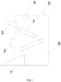
- FIG. 1 is a schematic structural diagram of an apparatus for steel slag carbon fixation in the present application.
- the apparatus for steel slag carbon fixation includes an apparatus body 6, and a spray thrower 4 and a gas outlet 5 arranged at a top of a structure of the apparatus body 6, a material inlet 3, a material outlet 1 and a gas inlet 2 are further formed on the apparatus body 6, a position of the material inlet 3 is higher than a position of the material outlet 1, the gas inlet 2 is located between the material inlet 3 and the material outlet 1, a transfer unit 7 is arranged inside the apparatus body 6, and the transfer unit 7 includes a plurality of transfer mechanisms.
- steel slag with a water content meeting a requirement is fed onto the transfer mechanisms through the material inlet 3, an arrangement angle of each transfer mechanism may be adjusted at will so as to guarantee that the steel slag may be spread on the transfer mechanism as thin as possible, the transfer mechanisms drive the steel slag to be transferred, in a transfer process, industrial waste gas containing carbon dioxide or containing carbon dioxide and sulfur dioxide is fed from the gas inlet 2, reclaimed water or the industrial waste gas is sprayed from the spray thrower 4, so environment humidity in the apparatus body 6 is maintained, and the steel slag of which carbon fixation is completed is delivered out via the material outlet 1.
- a feeding mode of the present application may adopt spiral feeding, transfer feeding, vibrating feeding or other modes, preferably, the vibrating feeding mode, and the steel slag can be spread on the transfer unit 7 more uniformly by maintaining a certain vibration frequency.
- a discharging mode of the present application may adopt spiral discharging, transfer discharging, vibrating discharging or other modes, preferably, the vibrating discharging mode, which is more beneficial for discharging of the steel slag, too high humidity is avoided, and the steel slag adheres to the material outlet 1.
- the present application does not limit a type, material, number and arranging position of the transfer mechanisms of the transfer unit 7 as long as the steel slag can be transferred, an angle formed between each transfer mechanism and a horizontal line is set as an inclined angle of the transfer mechanism, the inclined angle of the transfer mechanism may be adjusted at will so as to guarantee that the steel slag can be spread on the transfer mechanism as thin as possible.
- the transfer mechanism of the present application may be a transfer belt, protrusions are arranged on a belt of each transfer belt and are configured to increase frictional force between the belt and the steel slag, and each transfer belt is arranged at a certain inclined angle and configured to make the steel slag on the last transfer belt fall onto the next transfer belt under an action of gravity.
- the transfer mechanisms are two transfer belts, one end of the first transfer belt is arranged at the material inlet and configured to hold steel slag of the material inlet 3, the other end of the first transfer belt is arranged above one end of the second transfer belt, the second transfer belt is configured to hold the steel slag on the first transfer belt and transfer the steel slag to the material outlet 1, and by arranging the two transfer belts, spreading of the steel slag can be better achieved, and thus the steel slag makes full contact with the industrial waste gas.
- the present application does not limit a type, an arrangement position and an arrangement number of the spray thrower 4 as long as the environment humidity in the apparatus can be maintained in a range from 80% to 100%, and optionally, the spray thrower 4 is a plurality of liquid drop spray throwers which are uniformly arranged at the top of the apparatus so as to guarantee that the environment humidity in the apparatus is uniform.
- an initial content of the free calcium oxide is 8%, an initial content of chlorine is 0.015%, and an initial content of sulfur is 0.07%.
- This example provides a method for steel slag carbon fixation, and the specific steps and the method are as follows:
- This example provides a method for steel slag carbon fixation, and the specific steps and the method are as follows:
- This example provides a method for steel slag carbon fixation, and the specific steps and the method are as follows:
- This example provides a method for steel slag carbon fixation, and the specific steps and the method are as follows:
- This example provides a method for steel slag carbon fixation, and the specific steps and the method are the same as Example 3 and have a difference from Example 3 that a volume content of SO 2 in the industrial waste gas is 300 ppm.
- This example provides a method for steel slag carbon fixation, and the specific steps and the method are the same as Example 1 and have a difference from Example 1 that control over a water content of fed steel slag is implemented through soaking.
- This example provides a method for steel slag carbon fixation, and the specific steps and the method are as follows: it is controlled before feeding that 70% of steel slag has a particle diameter being less than or equal to 80 ⁇ m, and feeding is performed under a condition of guaranteeing that a water content of the steel slag is 5%, where the water content of the steel slag is controlled by spraying water to the steel slag, a structure shown in FIG.
- the steel slag with the water content meeting a standard is transferred onto the transfer mechanisms through a material inlet 3 according to a feeding rate of the steel slag being 1 t/h
- the transfer mechanisms are two transfer belts, inclined angles of the two transfer belts are controlled to be 25°
- the steel slag on the material outlet 1 can be uniformly spread on the transfer belts
- the steel slag on the last transfer belt falls onto the next transfer belt under an action of gravity
- the steel slag is transferred in the apparatus body 6, at the same time
- the spray thrower 4 continuously sprays reclaimed water drops into the apparatus body 6 so as to maintain humidity in the apparatus body 6 to be 100%
- the gas inlet 2 blows industrial waste gas containing CO 2 into the apparatus body 6, a proportion of CO 2 in the industrial waste gas containing CO 2 is greater than or equal to15%
- an injection rate of the industrial waste gas is 150,000 m 3 /h
- a transfer rate of each transfer belt is controlled to be 1.5 m/min
- This comparative example of the present application provides a method for steel slag carbon fixation, and the specific steps and the method are the same as Example 1 and have a difference from Example 1 that environment humidity in the apparatus for steel slag carbon fixation is maintained to be 60%.
- This comparative example of the present application provides a method for steel slag carbon fixation, and the specific steps and the method are the same as Example 1 and have a difference from Example 1 that spraying is not performed in a process of steel slag carbon fixation.
- a content of free calcium oxide, a content of chlorine and a content of sulfur in the steel slag after being treated by the methods for steel slag carbon fixation in Examples 1 to 5 and Comparative examples 1 to 2 are tested, a test method adopts YB/T140-2009 Method for chemical analysis of steel slag, and test results are shown in Table 1.
- the content of the free calcium oxide, the content of chlorine and the content of sulfur in the steel slag after being treated by the methods for steel slag carbon fixation in Examples 1 to 5 of the present application conform to regulations for chemical components in steel slag powder in a national standard GB/T20491-2017, and as the content of the free calcium oxide in the steel slag treated by the methods is far less than the regulated standard, the steel slag produced by the methods also has wider application potential.
Landscapes
- Engineering & Computer Science (AREA)
- Chemical & Material Sciences (AREA)
- Environmental & Geological Engineering (AREA)
- Chemical Kinetics & Catalysis (AREA)
- General Chemical & Material Sciences (AREA)
- Health & Medical Sciences (AREA)
- Biomedical Technology (AREA)
- Analytical Chemistry (AREA)
- Oil, Petroleum & Natural Gas (AREA)
- Ceramic Engineering (AREA)
- Organic Chemistry (AREA)
- Materials Engineering (AREA)
- Structural Engineering (AREA)
- Metallurgy (AREA)
- Manufacturing & Machinery (AREA)
- Life Sciences & Earth Sciences (AREA)
- General Life Sciences & Earth Sciences (AREA)
- Geology (AREA)
- Mechanical Engineering (AREA)
- Carbon Steel Or Casting Steel Manufacturing (AREA)
- Furnace Details (AREA)
- Treating Waste Gases (AREA)
- Gas Separation By Absorption (AREA)
- Carbon And Carbon Compounds (AREA)
Applications Claiming Priority (2)
| Application Number | Priority Date | Filing Date | Title |
|---|---|---|---|
| CN202310911825.8A CN116920605A (zh) | 2023-07-24 | 2023-07-24 | 一种钢渣固碳的装置及方法 |
| PCT/CN2023/134428 WO2025020390A1 (zh) | 2023-07-24 | 2023-11-27 | 一种钢渣固碳的装置及方法 |
Publications (2)
| Publication Number | Publication Date |
|---|---|
| EP4520737A1 true EP4520737A1 (de) | 2025-03-12 |
| EP4520737A4 EP4520737A4 (de) | 2026-03-18 |
Family
ID=88393884
Family Applications (1)
| Application Number | Title | Priority Date | Filing Date |
|---|---|---|---|
| EP23915185.5A Pending EP4520737A4 (de) | 2023-07-24 | 2023-11-27 | Vorrichtung und verfahren zur kohlenstoffsequestrierung von stahlschlacke |
Country Status (6)
| Country | Link |
|---|---|
| US (1) | US20250161873A1 (de) |
| EP (1) | EP4520737A4 (de) |
| JP (1) | JP2025527966A (de) |
| KR (1) | KR20250017198A (de) |
| CN (1) | CN116920605A (de) |
| WO (1) | WO2025020390A1 (de) |
Families Citing this family (5)
| Publication number | Priority date | Publication date | Assignee | Title |
|---|---|---|---|---|
| CN116920605A (zh) * | 2023-07-24 | 2023-10-24 | 江苏省沙钢钢铁研究院有限公司 | 一种钢渣固碳的装置及方法 |
| CN118594226A (zh) * | 2024-05-21 | 2024-09-06 | 原初科技(北京)有限公司 | 一种矿化空气中co2的系统及方法 |
| CN118849178B (zh) * | 2024-06-27 | 2026-03-20 | 马鞍山钢铁有限公司 | 一种钢渣尾渣固定二氧化碳的系统和方法 |
| WO2026048175A1 (ja) * | 2024-08-26 | 2026-03-05 | Jfeスチール株式会社 | 炭酸化物含有粒状材の製造方法 |
| CN120796605A (zh) * | 2025-09-12 | 2025-10-17 | 中冶建筑研究总院有限公司 | 一种高温钢渣处理系统、方法及智能化控制装置 |
Family Cites Families (23)
| Publication number | Priority date | Publication date | Assignee | Title |
|---|---|---|---|---|
| JP2000350976A (ja) * | 1999-06-11 | 2000-12-19 | Kawasaki Steel Corp | 粉粒状製鋼スラグの固化方法 |
| KR100590994B1 (ko) * | 2004-09-08 | 2006-06-19 | 재단법인 포항산업과학연구원 | 제강슬래그의 에이징 방법 |
| JP4808655B2 (ja) * | 2007-03-06 | 2011-11-02 | 新日本製鐵株式会社 | 粉状製鋼スラグの安定化処理方法 |
| CN101269920A (zh) * | 2007-03-23 | 2008-09-24 | 宝山钢铁股份有限公司 | 钢渣碳酸化处理方法 |
| JP4856661B2 (ja) * | 2008-02-22 | 2012-01-18 | 新日本製鐵株式会社 | 製鋼スラグの安定化処理方法 |
| CN101612510B (zh) * | 2008-06-25 | 2011-10-05 | 中国科学院大连化学物理研究所 | 一种吸收co2的微通道吸收器 |
| CN106540525B (zh) * | 2016-11-25 | 2019-01-15 | 江西理工大学 | 一种协同利用炉渣和废水稳定废气中co2的方法及装置 |
| CN108786457A (zh) * | 2017-05-02 | 2018-11-13 | 中国石油化工股份有限公司 | 烟气脱硝方法及脱硝反应器 |
| CN108404645A (zh) * | 2018-03-21 | 2018-08-17 | 宁波大学 | 一种错位式钢渣脱除二氧化碳的装置 |
| CN109574610B (zh) * | 2019-01-21 | 2020-11-13 | 北京科技大学 | 一种利用钢渣高效制备低成本碳化砖的方法 |
| CN110665614B (zh) * | 2019-10-10 | 2021-09-07 | 山东祥桓环境科技有限公司 | 一种钢渣粉碎及固碳处理系统及其应用 |
| WO2021188682A1 (en) * | 2020-03-20 | 2021-09-23 | The Regents Of The University Of Michigan | Sequestering carbon dioxide into precursors of bendabue engineered cementitious composites |
| CN112430051A (zh) * | 2020-11-30 | 2021-03-02 | 山西大学 | 钢渣-脱硫石膏-粉煤灰协同碳化制备的建材及方法 |
| CN112899420B (zh) * | 2021-01-18 | 2022-02-25 | 山东大学 | 一种转炉渣联用淬化消碱磁化热回收装置和方法 |
| CN113149495A (zh) * | 2021-05-26 | 2021-07-23 | 南京腾达环保科技有限公司 | 一种利用含co2尾气风淬预处理钢渣的装置及方法 |
| CN113680190A (zh) * | 2021-09-23 | 2021-11-23 | 生态环境部南京环境科学研究所 | 一种固体废物焚烧碳捕捉装置 |
| CN113831030A (zh) * | 2021-10-11 | 2021-12-24 | 江苏永联精筑建设集团有限公司 | 一种钢渣快速陈化装置 |
| CN115196898B (zh) * | 2022-07-05 | 2024-09-06 | 北京建筑材料科学研究总院有限公司 | 一种利用均化-碳化协同制备低碳掺合料的方法及装置 |
| CN115448628B (zh) * | 2022-09-23 | 2023-08-25 | 天津水泥工业设计研究院有限公司 | 一种碳化多孔钢渣骨料及其制备方法 |
| CN115611534A (zh) * | 2022-10-18 | 2023-01-17 | 山西太钢不锈钢股份有限公司 | 一种碳钢渣固渣固碳的方法 |
| CN115677248B (zh) * | 2022-10-26 | 2024-01-30 | 中国建筑材料科学研究总院有限公司 | 一种固碳轻骨料及其制备方法 |
| CN116422120A (zh) * | 2023-05-24 | 2023-07-14 | 佛山赛因迪环保科技有限公司 | 一种逆流式干法脱硫装置 |
| CN116920605A (zh) * | 2023-07-24 | 2023-10-24 | 江苏省沙钢钢铁研究院有限公司 | 一种钢渣固碳的装置及方法 |
-
2023
- 2023-07-24 CN CN202310911825.8A patent/CN116920605A/zh active Pending
- 2023-11-27 JP JP2024541141A patent/JP2025527966A/ja active Pending
- 2023-11-27 EP EP23915185.5A patent/EP4520737A4/de active Pending
- 2023-11-27 US US18/726,693 patent/US20250161873A1/en active Pending
- 2023-11-27 WO PCT/CN2023/134428 patent/WO2025020390A1/zh active Pending
- 2023-11-27 KR KR1020247030271A patent/KR20250017198A/ko active Pending
Also Published As
| Publication number | Publication date |
|---|---|
| JP2025527966A (ja) | 2025-08-26 |
| WO2025020390A1 (zh) | 2025-01-30 |
| KR20250017198A (ko) | 2025-02-04 |
| CN116920605A (zh) | 2023-10-24 |
| EP4520737A4 (de) | 2026-03-18 |
| US20250161873A1 (en) | 2025-05-22 |
Similar Documents
| Publication | Publication Date | Title |
|---|---|---|
| EP4520737A1 (de) | Vorrichtung und verfahren zur kohlenstoffsequestrierung von stahlschlacke | |
| CN112125541A (zh) | 一种湿法碳化活化废旧混凝土再生微粉的方法及再生微粉的应用 | |
| US4224295A (en) | Process for the production of finely divided silicic acid by spray drying | |
| US20230352679A1 (en) | Mixing process for preparing high nickel cathode material and application thereof | |
| RU2224007C1 (ru) | Угольный брикет, обладающий повышенной прочностью, а также способ его изготовления | |
| CN110465177B (zh) | 赤泥综合利用处理方法 | |
| CN1086959C (zh) | 一种烟气脱硫剂和烟气脱硫方法 | |
| CN114824162A (zh) | 一种锂离子电池石墨类负极材料石墨化工艺及系统 | |
| US11027234B2 (en) | Oxidization of ammonia desulfurization solution | |
| CN108800147A (zh) | 低氮氧化物焚烧工艺及其装置 | |
| CN113578005B (zh) | 一种烟气循环流化床半干法脱硫的方法 | |
| Xing et al. | From laboratory to industry: Preparation and mechanism analysis of organic additive-modified high-activity calcium hydroxide desulfurizer in low-temperature dry desulfurization | |
| CN115430272A (zh) | 一种钙基sds脱硫工艺原料的制备方法 | |
| CN104773742B (zh) | 一种粗硫酸铵的精制方法 | |
| CN104418376A (zh) | 一种沉淀碳酸钙的生产工艺 | |
| RU2227792C1 (ru) | Способ получения сульфатонитрата аммония | |
| CN115945058B (zh) | 氢氧化钙条状脱硫剂及其制备方法 | |
| CN119633696A (zh) | 一种用于固废高效矿化二氧化碳的流化反应装置及方法 | |
| CN106039963A (zh) | 干法水泥窑氨法半干法脱硫装置与方法 | |
| CN111233020A (zh) | 一种利用工业副产物石膏制备氧化钙和硫磺的系统和方法 | |
| CN108084365B (zh) | 一种高吸水性树脂的制备方法及其制备装置 | |
| CN110368799B (zh) | 一种半干法脱硫装置及方法 | |
| CN100536996C (zh) | 处理碱活化的废气的方法及其设备 | |
| CN206198984U (zh) | 干法水泥窑氨法半干法脱硫装置 | |
| CN114073889A (zh) | 一种用于烟气经氧化后的脱硝剂及其脱硝工艺 |
Legal Events
| Date | Code | Title | Description |
|---|---|---|---|
| STAA | Information on the status of an ep patent application or granted ep patent |
Free format text: STATUS: UNKNOWN |
|
| STAA | Information on the status of an ep patent application or granted ep patent |
Free format text: STATUS: THE INTERNATIONAL PUBLICATION HAS BEEN MADE |
|
| PUAI | Public reference made under article 153(3) epc to a published international application that has entered the european phase |
Free format text: ORIGINAL CODE: 0009012 |
|
| STAA | Information on the status of an ep patent application or granted ep patent |
Free format text: STATUS: REQUEST FOR EXAMINATION WAS MADE |
|
| 17P | Request for examination filed |
Effective date: 20240717 |
|
| AK | Designated contracting states |
Kind code of ref document: A1 Designated state(s): AL AT BE BG CH CY CZ DE DK EE ES FI FR GB GR HR HU IE IS IT LI LT LU LV MC ME MK MT NL NO PL PT RO RS SE SI SK SM TR |
|
| A4 | Supplementary search report drawn up and despatched |
Effective date: 20260216 |
|
| RIC1 | Information provided on ipc code assigned before grant |
Ipc: C04B 5/06 20060101AFI20260210BHEP Ipc: C04B 28/08 20060101ALI20260210BHEP Ipc: B01D 53/83 20060101ALI20260210BHEP Ipc: C22B 7/04 20060101ALI20260210BHEP Ipc: B01D 53/62 20060101ALI20260210BHEP Ipc: C21B 3/04 20060101ALI20260210BHEP |