EP4520718A1 - Vorrichtung zur herstellung von kohlenstoffmaterial, system zur herstellung von kohlenstoffmaterial, kohlenstoffzirkulationssystem, verfahren zur herstellung von kohlenstoffmaterial und kohlenstoffzirkulationsverfahren - Google Patents
Vorrichtung zur herstellung von kohlenstoffmaterial, system zur herstellung von kohlenstoffmaterial, kohlenstoffzirkulationssystem, verfahren zur herstellung von kohlenstoffmaterial und kohlenstoffzirkulationsverfahren Download PDFInfo
- Publication number
- EP4520718A1 EP4520718A1 EP23799492.6A EP23799492A EP4520718A1 EP 4520718 A1 EP4520718 A1 EP 4520718A1 EP 23799492 A EP23799492 A EP 23799492A EP 4520718 A1 EP4520718 A1 EP 4520718A1
- Authority
- EP
- European Patent Office
- Prior art keywords
- carbon
- gas
- carbon material
- reductant
- material manufacturing
- Prior art date
- Legal status (The legal status is an assumption and is not a legal conclusion. Google has not performed a legal analysis and makes no representation as to the accuracy of the status listed.)
- Pending
Links
Images




Classifications
-
- B—PERFORMING OPERATIONS; TRANSPORTING
- B01—PHYSICAL OR CHEMICAL PROCESSES OR APPARATUS IN GENERAL
- B01J—CHEMICAL OR PHYSICAL PROCESSES, e.g. CATALYSIS OR COLLOID CHEMISTRY; THEIR RELEVANT APPARATUS
- B01J8/00—Chemical or physical processes in general, conducted in the presence of fluids and solid particles; Apparatus for such processes
- B01J8/02—Chemical or physical processes in general, conducted in the presence of fluids and solid particles; Apparatus for such processes with stationary particles, e.g. in fixed beds
- B01J8/04—Chemical or physical processes in general, conducted in the presence of fluids and solid particles; Apparatus for such processes with stationary particles, e.g. in fixed beds the fluid passing successively through two or more beds
- B01J8/0492—Feeding reactive fluids
-
- B—PERFORMING OPERATIONS; TRANSPORTING
- B01—PHYSICAL OR CHEMICAL PROCESSES OR APPARATUS IN GENERAL
- B01D—SEPARATION
- B01D53/00—Separation of gases or vapours; Recovering vapours of volatile solvents from gases; Chemical or biological purification of waste gases, e.g. engine exhaust gases, smoke, fumes, flue gases, aerosols
- B01D53/34—Chemical or biological purification of waste gases
- B01D53/46—Removing components of defined structure
- B01D53/62—Carbon oxides
-
- B—PERFORMING OPERATIONS; TRANSPORTING
- B01—PHYSICAL OR CHEMICAL PROCESSES OR APPARATUS IN GENERAL
- B01D—SEPARATION
- B01D53/00—Separation of gases or vapours; Recovering vapours of volatile solvents from gases; Chemical or biological purification of waste gases, e.g. engine exhaust gases, smoke, fumes, flue gases, aerosols
- B01D53/34—Chemical or biological purification of waste gases
- B01D53/74—General processes for purification of waste gases; Apparatus or devices specially adapted therefor
- B01D53/86—Catalytic processes
- B01D53/8671—Removing components of defined structure not provided for in B01D53/8603 - B01D53/8668
-
- B—PERFORMING OPERATIONS; TRANSPORTING
- B01—PHYSICAL OR CHEMICAL PROCESSES OR APPARATUS IN GENERAL
- B01J—CHEMICAL OR PHYSICAL PROCESSES, e.g. CATALYSIS OR COLLOID CHEMISTRY; THEIR RELEVANT APPARATUS
- B01J8/00—Chemical or physical processes in general, conducted in the presence of fluids and solid particles; Apparatus for such processes
- B01J8/001—Controlling catalytic processes
-
- C—CHEMISTRY; METALLURGY
- C01—INORGANIC CHEMISTRY
- C01B—NON-METALLIC ELEMENTS; COMPOUNDS THEREOF; METALLOIDS OR COMPOUNDS THEREOF NOT COVERED BY SUBCLASS C01C
- C01B32/00—Carbon; Compounds thereof
- C01B32/05—Preparation or purification of carbon not covered by groups C01B32/15, C01B32/20, C01B32/25, C01B32/30
-
- C—CHEMISTRY; METALLURGY
- C01—INORGANIC CHEMISTRY
- C01B—NON-METALLIC ELEMENTS; COMPOUNDS THEREOF; METALLOIDS OR COMPOUNDS THEREOF NOT COVERED BY SUBCLASS C01C
- C01B32/00—Carbon; Compounds thereof
- C01B32/40—Carbon monoxide
-
- C—CHEMISTRY; METALLURGY
- C01—INORGANIC CHEMISTRY
- C01B—NON-METALLIC ELEMENTS; COMPOUNDS THEREOF; METALLOIDS OR COMPOUNDS THEREOF NOT COVERED BY SUBCLASS C01C
- C01B32/00—Carbon; Compounds thereof
- C01B32/50—Carbon dioxide
-
- C—CHEMISTRY; METALLURGY
- C21—METALLURGY OF IRON
- C21B—MANUFACTURE OF IRON OR STEEL
- C21B13/00—Making spongy iron or liquid steel, by direct processes
- C21B13/0006—Making spongy iron or liquid steel, by direct processes obtaining iron or steel in a molten state
-
- C—CHEMISTRY; METALLURGY
- C21—METALLURGY OF IRON
- C21B—MANUFACTURE OF IRON OR STEEL
- C21B13/00—Making spongy iron or liquid steel, by direct processes
- C21B13/0066—Preliminary conditioning of the solid carbonaceous reductant
-
- C—CHEMISTRY; METALLURGY
- C21—METALLURGY OF IRON
- C21B—MANUFACTURE OF IRON OR STEEL
- C21B5/00—Making pig-iron in the blast furnace
- C21B5/06—Making pig-iron in the blast furnace using top gas in the blast furnace process
-
- C—CHEMISTRY; METALLURGY
- C21—METALLURGY OF IRON
- C21B—MANUFACTURE OF IRON OR STEEL
- C21B7/00—Blast furnaces
- C21B7/002—Evacuating and treating of exhaust gases
-
- C—CHEMISTRY; METALLURGY
- C25—ELECTROLYTIC OR ELECTROPHORETIC PROCESSES; APPARATUS THEREFOR
- C25B—ELECTROLYTIC OR ELECTROPHORETIC PROCESSES FOR THE PRODUCTION OF COMPOUNDS OR NON-METALS; APPARATUS THEREFOR
- C25B1/00—Electrolytic production of inorganic compounds or non-metals
- C25B1/01—Products
- C25B1/23—Carbon monoxide or syngas
-
- C—CHEMISTRY; METALLURGY
- C25—ELECTROLYTIC OR ELECTROPHORETIC PROCESSES; APPARATUS THEREFOR
- C25B—ELECTROLYTIC OR ELECTROPHORETIC PROCESSES FOR THE PRODUCTION OF COMPOUNDS OR NON-METALS; APPARATUS THEREFOR
- C25B15/00—Operating or servicing cells
- C25B15/08—Supplying or removing reactants or electrolytes; Regeneration of electrolytes
- C25B15/081—Supplying products to non-electrochemical reactors that are combined with the electrochemical cell, e.g. Sabatier reactor
-
- H—ELECTRICITY
- H01—ELECTRIC ELEMENTS
- H01M—PROCESSES OR MEANS, e.g. BATTERIES, FOR THE DIRECT CONVERSION OF CHEMICAL ENERGY INTO ELECTRICAL ENERGY
- H01M4/00—Electrodes
- H01M4/02—Electrodes composed of, or comprising, active material
- H01M4/36—Selection of substances as active materials, active masses, active liquids
- H01M4/58—Selection of substances as active materials, active masses, active liquids of inorganic compounds other than oxides or hydroxides, e.g. sulfides, selenides, tellurides, halogenides or LiCoFy; of polyanionic structures, e.g. phosphates, silicates or borates
- H01M4/583—Carbonaceous material, e.g. graphite-intercalation compounds or CFx
- H01M4/587—Carbonaceous material, e.g. graphite-intercalation compounds or CFx for inserting or intercalating light metals
-
- H—ELECTRICITY
- H01—ELECTRIC ELEMENTS
- H01M—PROCESSES OR MEANS, e.g. BATTERIES, FOR THE DIRECT CONVERSION OF CHEMICAL ENERGY INTO ELECTRICAL ENERGY
- H01M4/00—Electrodes
- H01M4/02—Electrodes composed of, or comprising, active material
- H01M4/62—Selection of inactive substances as ingredients for active masses, e.g. binders, fillers
- H01M4/624—Electric conductive fillers
- H01M4/625—Carbon or graphite
-
- B—PERFORMING OPERATIONS; TRANSPORTING
- B01—PHYSICAL OR CHEMICAL PROCESSES OR APPARATUS IN GENERAL
- B01D—SEPARATION
- B01D2251/00—Reactants
- B01D2251/20—Reductants
- B01D2251/202—Hydrogen
-
- B—PERFORMING OPERATIONS; TRANSPORTING
- B01—PHYSICAL OR CHEMICAL PROCESSES OR APPARATUS IN GENERAL
- B01D—SEPARATION
- B01D2257/00—Components to be removed
- B01D2257/50—Carbon oxides
- B01D2257/502—Carbon monoxide
-
- B—PERFORMING OPERATIONS; TRANSPORTING
- B01—PHYSICAL OR CHEMICAL PROCESSES OR APPARATUS IN GENERAL
- B01D—SEPARATION
- B01D2257/00—Components to be removed
- B01D2257/50—Carbon oxides
- B01D2257/504—Carbon dioxide
-
- B—PERFORMING OPERATIONS; TRANSPORTING
- B01—PHYSICAL OR CHEMICAL PROCESSES OR APPARATUS IN GENERAL
- B01D—SEPARATION
- B01D2258/00—Sources of waste gases
- B01D2258/02—Other waste gases
- B01D2258/0283—Flue gases
-
- B—PERFORMING OPERATIONS; TRANSPORTING
- B01—PHYSICAL OR CHEMICAL PROCESSES OR APPARATUS IN GENERAL
- B01J—CHEMICAL OR PHYSICAL PROCESSES, e.g. CATALYSIS OR COLLOID CHEMISTRY; THEIR RELEVANT APPARATUS
- B01J2208/00—Processes carried out in the presence of solid particles; Reactors therefor
- B01J2208/00008—Controlling the process
- B01J2208/00539—Pressure
-
- C—CHEMISTRY; METALLURGY
- C25—ELECTROLYTIC OR ELECTROPHORETIC PROCESSES; APPARATUS THEREFOR
- C25B—ELECTROLYTIC OR ELECTROPHORETIC PROCESSES FOR THE PRODUCTION OF COMPOUNDS OR NON-METALS; APPARATUS THEREFOR
- C25B9/00—Cells or assemblies of cells; Constructional parts of cells; Assemblies of constructional parts, e.g. electrode-diaphragm assemblies; Process-related cell features
- C25B9/17—Cells comprising dimensionally-stable non-movable electrodes; Assemblies of constructional parts thereof
- C25B9/19—Cells comprising dimensionally-stable non-movable electrodes; Assemblies of constructional parts thereof with diaphragms
- C25B9/23—Cells comprising dimensionally-stable non-movable electrodes; Assemblies of constructional parts thereof with diaphragms comprising ion-exchange membranes in or on which electrode material is embedded
Definitions
- the present disclosure relates to a carbon material manufacturing apparatus, a carbon material manufacturing system, a carbon cycle system, a carbon material manufacturing method and a carbon cycle method.
- Carbon materials have been widely used as conductive materials for electronic devices and filler materials for tires and ink.
- Patent Document 1 discloses a method for manufacturing a carbon material by combustion of coal. However, it is considered that, in such a method, a large amount of carbon dioxide (CO 2 ) is contained in gas from which the carbon material is separated in a final step.
- CO 2 carbon dioxide
- lithium-ion secondary batteries have been developed.
- active materials used for positive electrodes and negative electrodes are also keenly examined.
- Patent Document 2 discloses a method for manufacturing a carbon-based negative electrode active material that is superior in accepting lithium ions.
- a method including: pulverizing petroleum-based or coal-based coke; adjusting particle sizes; and then performing heat treatment is disclosed.
- a carbon material manufactured by the method disclosed in Patent Document 1 can also be used as the above carbon-based negative electrode active material.
- a method is afraid of increasing the concentration of carbon dioxide in the atmosphere and contributing to the global warming, as described above.
- Coke as a reductant is fed into a smelting furnace together with mineral ore as a raw material, so that the mineral ore is melted to extract the target metal.
- Coke is generally manufactured from coal (see Patent Document 2).
- Coal is a kind of fossil fuel, and a large amount of carbon dioxide is generated when it is combusted. If emitting this carbon dioxide directly into the atmosphere, the concentration of carbon dioxide in the atmosphere is afraid of being increased and contributing to the global warming.
- the present disclosure provides a carbon material manufacturing apparatus, a carbon material manufacturing system and a carbon material manufacturing method, which can manufacture a carbon material efficiently from carbon dioxide.
- a carbon-based negative electrode active material manufactured from coke contains a relatively low amount of an impurity (solid impurity) due to a relatively low content of the impurity in the coke itself.
- an impurity solid impurity
- the content of the solid impurity in the carbon-based negative electrode active material (carbon material) is smaller.
- low load on the environment is also preferable.
- the inventors of the present disclosure have provided a carbon material manufacturing apparatus and the like, which can manufacture a carbon material with an extremely small content of the solid impurity, while preventing the environmental load.
- the present disclosure provides a carbon cycle system and a carbon cycle method, which can manufacture a target metal efficiently by using the carbon material generated from exhaust gas.
- a carbon material manufacturing apparatus includes: a first reaction unit configured to generate carbon monoxide from carbon dioxide; a second reaction unit configured to generate a carbon material from the carbon monoxide; and a gas line connecting the first reaction unit and the second reaction unit.
- the first reaction unit includes at least one reactor storing a reductant. The reductant is allowed to contact source gas containing the carbon dioxide so as to reduce the carbon dioxide to convert the carbon dioxide into the carbon monoxide and to convert the reductant itself into an oxidized state, and the reductant in the oxidized state is then reduced by the contact with the reduction gas.
- the carbon material can be efficiently manufactured from carbon dioxide.
- the carbon material manufacturing apparatus includes: a first reaction unit configured to generate carbon monoxide from carbon dioxide; a second reaction unit configured to generate a carbon material from the carbon monoxide; a gas line connecting the first reaction unit and the second reaction unit; and a pressure adjustment unit configured to be provided in middle of the gas line and increase pressure of gas passing through the gas line.
- the carbon material can be efficiently manufactured from carbon dioxide.
- the carbon material manufacturing apparatus includes: a first reaction unit configured to generate carbon monoxide from carbon dioxide; a second reaction unit configured to generate a carbon material from the carbon monoxide.
- the content of the solid impurity in the carbon material is 1% by mass or less.
- the carbon material with the extremely low content of the impurity can be manufactured, while preventing the environmental load.
- the effective use of such exhaust gas can save its emission, thereby realizing the circular economy (material recycling society).
- the carbon cycle system includes: a first reaction unit configured to generate carbon monoxide from carbon dioxide contained in the exhaust gas; a second reaction unit configured to generate a carbon material from the carbon monoxide; and a smelting furnace configured to be supplied with mineral ore together with the carbon material and smelt the mineral ore.
- the first reaction unit has at least one reactor which accommodates a reduced object that converts carbon dioxide into carbon monoxide by a reduction reaction caused by the contact with exhaust gas, and can separate at least a part of oxygen elements eliminated from the carbon dioxide, in a system of the reduction reaction.
- the reduced object is a reductant which reduces carbon dioxide by contact with the exhaust gas so as to convert the carbon dioxide into carbon monoxide and convert itself into an oxidized state
- the reductant in the oxidized state is a reductant which is reduced by contact with reduction gas that contains a reductant material.
- the carbon material generated from the exhaust gas can be used to manufacture target metal efficiently.
- the effective use of such exhaust gas can save its emission, thereby realizing the circular economy (material recycling society).
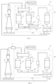
- FIG. 1 is a schematic view illustrating a configuration of the first embodiment of the carbon material manufacturing system of the present disclosure.
- FIG. 2 is a schematic view illustrating a configuration of a first reactor in the first embodiment.
- the carbon material manufacturing system 10 illustrated in FIG. 1 is a system for manufacturing a carbon material, and includes: a carbon material manufacturing apparatus 100 (hereinafter, simply referred to as the "manufacturing apparatus 100"); an exhaust gas supply unit 1 which is connected to the manufacturing apparatus 100 and supplies exhaust gas (source gas containing carbon dioxide); and a reductant gas supply unit 2 that supplies reductant gas.
- a carbon material manufacturing apparatus 100 hereinafter, simply referred to as the "manufacturing apparatus 100"
- an exhaust gas supply unit 1 which is connected to the manufacturing apparatus 100 and supplies exhaust gas (source gas containing carbon dioxide); and a reductant gas supply unit 2 that supplies reductant gas.
- an upstream side along a flow direction of gas is also described simply as an "upstream side”
- a downstream side along the flow direction of the gas is also described simply as a “downstream side”.
- the exhaust gas supply unit 1 is not limited particularly, and may be, for example, a CO x emission source of at least one business operation selected from trash burning sites, paper factories, cement factories, steel works, refineries, thermal power plants, oil refineries, ethylene crackers, oil factories, chemical plants, etc.
- a furnace for example, a combustion furnace, a blast furnace or a converter furnace
- gas containing carbon dioxide is generated during combustion, melting, refining and the like of contents thereof.
- waste In the case of a combustion furnace (incinerator) in a trash burning site, examples of the contents (waste) include plastic waste, kitchen waste, municipal waste (MSW), waste tires, biomass waste, household trash (futon cushion, paper, etc.), construction materials, etc. Incidentally, such waste may contain one kind alone, two kinds or more of them.
- the exhaust gas generally contains not only carbon dioxide but also other gas components such as nitrogen, oxygen, carbon monoxide, water vapor, methane and the like. Concentration of carbon dioxide contained in the exhaust gas is not limited particularly, but, considering production costs of product gas (conversion efficiency into the carbon material), the concentration thereof is preferably 1% by volume or more, and more preferably 5% by volume or more.
- carbon dioxide is contained by 5% by volume or more and 15% by volume or less
- nitrogen is contained by 60% by volume or more and 70% by volume or less
- oxygen is contained by 5% by volume or more and 10% by volume or less
- water vapor is contained by 15% by volume or more and 25% by volume or less.
- the exhaust gas from a blast furnace is gas generated while manufacturing pig iron in the blast furnace, and contains carbon dioxide by 5% by volume or more and 45% by volume or less, nitrogen by 55% by volume or more and 60% by volume or less, carbon monoxide by 10% by volume or more and 40% by volume or less, and hydrogen by 1% by volume or more and 10% by volume or less.
- the exhaust gas from a converter furnace is gas generated while manufacturing steel in the converter furnace, and contains carbon dioxide by 15% by volume or more and 20% by volume or less, carbon monoxide by 50% by volume or more and 80% by volume or less, nitrogen by 15% by volume or more and 25% by volume or less, and hydrogen by 1% by volume or more and 5% by volume or less.
- pure gas containing 100% by volume of carbon dioxide may be used.
- untreated gas discharged from the furnace may be used directly as it is, and for example, treated gas (described below) after being treated for removing carbon monoxide and the like may also be used.
- the untreated blast furnace gas and converter furnace gas respectively have the above-described gas compositions, and the treated gas has a gas composition closer to the above-described composition of the exhaust gas from the combustion furnace.
- any kinds of the above-described gas gas before being supplied to the manufacturing apparatus 100 are called as exhaust gas.
- the reductant gas supply unit 2 is constituted of, for example, a hydrogen generator for generating hydrogen by electrolysis of water. To this hydrogen generator, a tank that stores water is connected.
- the hydrogen generator By the hydrogen generator, a large amount of hydrogen can be generated easily at a relatively low cost. Also, the hydrogen generator has an advantage of being able to reuse condensed water that is generated in the manufacturing apparatus 100 (same as in the carbon cycle system 1000 described below). In addition, since the hydrogen generator consumes high electric energy, use of electric power as renewable energy is effective.
- renewable energy electric energy using at least one selected from solar power generation, wind power generation, hydroelectric power generation, wave power generation, tidal power generation, biomass power generation, geothermal power generation, solar heat and geothermal heat can be used.
- a device for generating by-product hydrogen can also be used.
- the device for generating by-product hydrogen for example, devices for electrolyzing sodium chloride, devices for reforming petroleum with water vapor, devices for producing ammonia and the like can be exemplified.
- the reductant gas supply unit 2 can be a coke oven.
- exhaust gas from the coke oven may be used as the reductant gas.
- the exhaust gas from the coke oven can be used because of containing hydrogen and methane as main components, in particular, hydrogen by 50% by volume or more and 60% by volume or less.
- the manufacturing apparatus 100 of the present embodiment is an apparatus for manufacturing the carbon material, and mainly includes a gas switching unit 3, two first reactors 4a and 4b (first reaction unit 4) and one second reactor (second reaction unit) 5.
- the exhaust gas supply unit 1 is connected to the gas switching unit 3 via a gas line GL1, and the reductant gas supply unit 2 is connected to the gas switching unit 3 via a gas line GL2.
- a temperature control unit for adjusting a temperature of gas passing therethrough a pressurizing unit for pressurizing the gas, an impurity removal unit for removing an impurity from the gas and the like may also be disposed.
- the gas switching unit 3 can be configured to include, for example, a branch gas line and a flow channel opening/closing mechanism such as a valve which is provided in the middle of this branch gas line.
- the gas switching unit 3 is connected to inlet ports of the first reactors 4a and 4b via two gas lines GL3a and GL3b, respectively.
- the exhaust gas (source gas containing carbon dioxide) supplied from the exhaust gas supply unit 1 passes through the gas line GL1, the gas switching unit 3 and the gas lines GL3a and GL3b so as to be supplied to the first reactors 4a and 4b, respectively.
- the reductant gas containing hydrogen (reductant material) supplied from the reductant gas supply unit 2 passes through the gas line GL2, the gas switching unit 3 and the gas lines GL3a and GL3b, thereby supplying to the respective first reactors 4a and 4b.
- the first reactors 4a and 4b can generate carbon monoxide from carbon dioxide (can convert carbon dioxide into carbon monoxide).
- each of the first reactors 4a and 4b is constituted of a multi-pipe reaction apparatus (fixed bed-type reaction apparatus) including: plural pipes 41, each of which is filled with (accommodates) a reductant (reduced object) 4R; and a housing 42 in which the plurality pipes 41 are stored in an internal space 43.
- a multi-pipe reaction apparatus can secure sufficient opportunities for the reductant 4R, the exhaust gas and the reductant gas to contact each other. As a result, the conversion efficiency of carbon dioxide into carbon monoxide can be enhanced.
- each of the first reactors 4a and 4b can also be constituted of a reactor, which omits the pipes 41, and includes the housing 42 in which the internal space 43 is filled with the reductant 4R (that is, a simple reactor).
- the reductant 4R of the present embodiment is preferably particles (granular), scales, pellets or the like.
- the reductant 4R with such a shape can enhance a packing efficiency in the pipes 41, and increase a contact area with the gas to be supplied into the pipes 41 further more.
- an average particle diameter thereof is not particularly limited, but is preferably 1 mm or more and 50 mm or less, and more preferably 1 mm or more and 30 mm or less.
- the contact area between the reductant 4R and the exhaust gas (carbon dioxide) can be further increased, thereby improving the conversion efficiency of carbon dioxide into carbon monoxide.
- regeneration (reduction) of the reductant 4R by the reductant gas containing the reductant material can also be performed more efficiently.
- the reductant 4R in the particle shape is preferably a molded body produced by rolling granulation, by which its spheroidicity can be increased.
- reductant 4R may also be supported on a carrier.
- a constituent material of the carrier is required to be hardly denatured by contact with the exhaust gas (oxidation gas) in reaction conditions or the like, and examples thereof include, for example, carbon materials (graphite, graphene, carbon black, carbon nanotubes, activated charcoal, etc.), carbides such as Mo 2 C, zeolite, montmorillonite, oxides such as ZrO 2 , TiO 2 , V 2 O 5 , MgO, CeO 2 , Al 2 O 3 and SiO 2 , composite oxides including them, and the like.
- the constituent material of the carrier zeolite, montmorillonite, ZrO 2 , TiO 2 , V 2 O 5 , MgO, Al 2 O 3 , SiO 2 and the composite oxides including them are preferable.
- the carrier composed of such a material is preferable, because of not affecting negatively on the reaction of the reductant 4R and exhibiting an excellent performance of supporting the reductant 4R.
- the carrier does not interact with the reaction of the reductant 4R, but simply supports (holds) the reductant 4R.
- the reductant 4R contains at least one of metal and metal oxide (an oxygen carrier with oxygen ion conductivity).
- At least one of the metal and the metal oxide is not limited particularly as long as it can reduce carbon dioxide, but preferably contains at least one kind selected from metal elements that belong to Group III to Group XIII, more preferably contains at least one kind selected from metal elements that belong to Group III to Group XII, further preferably contains at least one kind of lanthanum, titanium, vanadium, iron, copper, zinc, nickel, manganese, chromium, cerium and the like, and is particularly preferably a metal oxide or a composite metal oxide that contains iron and/or cerium.
- These metal oxides are useful because of their particularly high conversion efficiencies of carbon dioxide into carbon monoxide.
- the metal a metal simple substance that contains only one kind of the above-described metallic elements and an alloy that contains two or more kinds of the above-described metallic elements are included.
- the reductant 4R (at least one of the metal and the metal oxide) may constitute the pipes (cylindrical molded bodies) 41 by itself. Furthermore, a block-shaped, lattice-shaped (for example, net-shaped or honeycomb-shaped) or other molded body may be made of the reductant 4R, and may be disposed in the housing 42. In these cases, the reductant 4R as a filler may be omitted, or other filler may be used together.
- the configuration in which the net-shaped body made of the reductant 4R and is disposed in the housing 42 is preferred.
- Such a configuration can prevent an increase of passing resistance of the exhaust gas and the reductant gas in each of the first reactors 4a and 4b, and can also secure sufficient opportunities for the reductant 4R to contact the exhaust gas and the reductant gas.
- volumes of the two first reactors 4a and 4b are set to be substantially equal to each other, and can be set appropriately according to an amount of the exhaust gas to be treated (a size of the exhaust gas supply unit 1 and a size of the manufacturing apparatus 100).
- the volumes of the two first reactors 4a and 4b may be different according to the kinds of the exhaust gas and the reductant gas, the performance of the reductant 4R or the like.
- the exhaust gas can be supplied to, for example, the first reactor 4a that accommodates the reductant 4R before oxidation via the gas line GL3a, and the reductant gas can be supplied to the first reactor 4b that accommodates the reductant 4R after the oxidation via the gas line GL3b.
- a reaction represented by following Formula 1 proceeds in the first reactor 4a
- a reaction represented by following Formula 2 proceeds in the first reactor 4b.
- the exhaust gas (source gas) and the reductant gas are switched to be supplied to the first reactor 4a and the first reactor 4b.
- the manufacturing apparatus 100 (carbon material manufacturing system 10) preferably further include a reductant heating unit (not illustrated in FIG. 1 ) for heating the reductant 4R when allowing the reductant 4R to contact the exhaust gas or the reductant gas (that is, when the exhaust gas or the reductant gas is reacted with the reductant 4R).
- a reductant heating unit (not illustrated in FIG. 1 ) for heating the reductant 4R when allowing the reductant 4R to contact the exhaust gas or the reductant gas (that is, when the exhaust gas or the reductant gas is reacted with the reductant 4R).
- a temperature of the reaction between the exhaust gas or the reductant gas and the reductant 4R can be maintained to be high so as to prevent or suppress the decrease of the conversion efficiency of carbon dioxide into carbon monoxide, and the regeneration of the reductant 4R by the reductant gas can be further promoted.
- the manufacturing apparatus 100 preferably has a reductant cooling unit for cooling the reductant 4R as a replace of the reductant heating unit.
- a reductant cooling unit for cooling the reductant 4R as a replace of the reductant heating unit.
- the manufacturing apparatus 100 is preferably provided with a reductant temperature control unit for adjusting the temperature of the reductant 4R depending on the kind of the reductant 4R (exothermic reaction or endothermic reaction).
- the conversion ratio of carbon dioxide into carbon monoxide in the first reactors 4a and 4b is preferably 70% or more, more preferably 85% or more, and further preferably 95% or more.
- An upper limit of the conversion ratio of carbon dioxide into carbon monoxide is generally about 98%.
- Such a conversion ratio can be set by adjusting the kind of the reductant 4R, the concentration of carbon dioxide contained in the exhaust gas, the kind of the reductant material, concentration of the reductant material contained in the reductant gas, temperatures of the first reactors 4a and 4b, flow rates (flow speed) of the exhaust gas and the reductant gas to the first reactors 4a and 4b, timing of switching between the exhaust gas and the reductant gas and the like.
- the gas lines GL4a and GL4b are connected to outlet ports of the first reactors 4a and 4b respectively, and merge at a gas merge junction J so as to constitute a gas line GL4. Further, in the middle of each of the gas lines GL4a and GL4b, a valve (not shown) is provided as necessary.
- passing speed of the exhaust gas and the reductant gas that pass through the first reactors 4a and 4b (that is, speed of processing the exhaust gas by the reductant 4R and speed of processing the reductant 4R by the reductant gas) can be set.
- the gas line GL4 is connected to an inlet port of the second reactor 5. That is, the second reactor (second reaction unit) 5 is connected to the first reactors 4a and 4b (first reaction unit) via the gas lines GL4a and GL4b and the gas line GL4. Thereby, the gas discharged from the first reactors 4a and 4b can be supplied to the second reactor 5 as mixture gas.
- the second reactor 5 can generate a carbon material from carbon monoxide (convert carbon monoxide into the carbon material). Specifically, the second reactor 5 generates the carbon material from the carbon monoxide contained in the mixture gas by a so-called Boudouard reaction as represented by following Formula 3.
- the pipe 41 is filled with one or more kinds of catalysts as follows.
- the catalysts include: (1) elements (simple substances or complexes) including tungsten, rhenium, osmium, tantalum, molybdenum, niobium, iridium, ruthenium, hafnium, technetium, rhodium, vanadium, chromium, zirconium, platinum, thorium, lutetium, titanium, palladium, protoactinium, thulium, scandium, iron, yttrium, erbium, cobalt, holmium, nickel, dysprosium, terbium, curium, gadolinium, beryllium, manganese, americium, promethium, uranium, copper, samarium, gold, actinium, neodymium, ber
- a pressure adjustment unit 8 for increasing pressure of the mixture gas that passes through the gas line GL4 is provided in the middle of the gas line GL4.
- equilibrium of the reaction represented by Formula 3 can be shifted (inclined) to the right, thereby further enhancing the generation efficiency of the carbon material.
- the pressure of the mixture gas after being pressurized by the pressure adjustment unit 8 is preferably 0.1 MPaG or more, more preferably 0.1 MPaG or more and 10 MPaG or less, further preferably 0.1 MPaG or more and 5 MPaG or less, particularly preferably 0.1 MPaG or more and 3 MPaG or less, and most preferably 0.1 MPaG or more and 2 MPaG or less.
- a lower limit of the pressure may be 0.2 MPaG or more, and may also be 0.5 MPaG or more.
- the pressure adjustment unit 8 can be configured to include a valve, a pressure adjustment valve or the like. Incidentally, the pressure adjustment unit 8 may be provided as necessary, or may be omitted.
- a cooler for cooling the mixture gas and a gas-liquid separator (not shown) may be provided.
- the cooler generates condensed water (liquid) by cooling the mixture gas.
- Such a cooler has a configuration similar to those of the first reactors 4a and 4b, jacket-type cooling devices in which jackets for allowing a refrigerant to pass through are arranged around piping (see FIG. 2 ), and may be configured to include a multi-pipe cooling device in which the mixture gas passes inside pipes and a refrigerant passes around the pipes, an air fin cooler or the like.
- the gas-liquid separator separates condensed water, which is generated when the mixed gas is cooled by the cooler, from the mixed gas.
- the condensed water has an advantage of dissolving and removing unnecessary gas components (in particular, the carbon dioxide) that remains in the mixture gas.
- the gas-liquid separator can be constituted of, for example, a simple container, a swirl flow separator, a centrifugal separator, a surface tension separator or the like.
- the gas-liquid separator is preferably constituted of a simple container, for its simple structure, low cost and the like.
- a filter that allows passage of gas but blocks passage of liquid may be disposed on an air-liquid interface in the container.
- the mixture gas with higher concentration of the carbon monoxide can be supplied to the second reactor 5. Therefore, the decrease of the conversion efficiency of the carbon monoxide into the carbon material can be prevented or suppressed, whereby the generation amount of the carbon material can be further increased.
- a second reaction temperature in the second reactor (second reaction unit) 5 is preferably lower than a first reaction temperature in the first reactors 4a and 4b (first reaction unit 4). In this case, heat of the reaction in the first reactors 4a and 4b can be used effectively in the second reactor 5.
- the second reaction temperature is preferably 850°C or less, more preferably 600°C or less, and further preferably 400°C or less.
- a gas line GL5 is connected to an outlet port of the second reactor 5.
- a product gas discharge unit 6 for discharging product gas to an outside of the manufacturing apparatus 100 is connected.
- the temperature (first reaction temperature) of the first reactor 4a (exhaust gas, reductant 4R) in above-described Step [2] is preferably 500°C or more, more preferably 650°C or more and 1100°C or less, and further preferably 700°C or more and 1000°C or less.
- the pressure (first reaction pressure) of the first reactor 4a is preferably less than 1 MPaG, more preferably 0.9 MPaG or less, and further preferably 0.2 MPaG or more and 0.8 MPaG or less.
- reaction conditions are set within the above ranges, for example, rapid decrease of temperature of the reductant 4R due to the endothermic reaction for converting the carbon dioxide into the carbon monoxide can be prevented or suppressed, whereby the reduction reaction of the carbon dioxide in the first reactor 4a can proceed more smoothly.
- the temperature (reaction temperature) of the first reactor 4b (reductant gas, reductant 4R) in above Step [4] is preferably 500°C or more, more preferably 650°C or more and 1100°C or less, and further preferably 700°C or more and 1000°C or less.
- the pressure (first reaction pressure) of the first reactor 4b is preferably less than 1 MPaG, more preferably 0.9 MPaG or less, and further preferably 0.2 MPaG or more and 0.8 MPaG or less.
- reaction conditions are set within the above ranges, for example, the rapid temperature decrease of the reductant 4R due to the endothermic reaction for reducing (regenerating) the reductant 4R in the oxidized state can be prevented or suppressed, whereby the reduction reaction of the reductant 4R in the first reactor 4b can proceed more smoothly.
- Steps [2] to [4] constitute the first generation step for generating the carbon monoxide from the carbon dioxide.
- a temperature of the mixture gas is generally 200°C or more and 1000°C or less. If the temperature of the mixture gas at this point is within the above range, it means that the temperature in the first reactors 4a and 4b is maintained at a sufficiently high temperature, so that it can be judged that the conversion of the carbon dioxide into the carbon monoxide by the reductant 4R and the reduction of the reductant 4R by the reductant gas are proceeding efficiently.
- this Step [6] constitutes a pressure adjustment step of increasing the pressure of the gas (mixture gas) generated in the first generation step.
- the mixture gas that has passed through the pressure adjustment unit 8 is supplied to the second reactor 5.
- the carbon monoxide is converted into a carbon material.
- this Step [7] constitutes a second generation step of generating the carbon material from carbon monoxide.
- the product gas (mixture gas) containing the carbon material is discharged from the product gas discharge unit 6 via the gas line GL5 to the outside of the manufacturing apparatus 100 so as to be subjected to a next step.
- gas lines GL6a and GL6b are branched off from middle of gas lines GL4a and GL4b respectively, and merge at a gas merge junction J1 so as to constitute a gas line GL6.
- switch valves are provided at branch portions between the gas lines GL4a and GL6a and between GL4b and GL6b, respectively.
- the exhaust gas discharged from the first reactors 4a and 4b passes through the gas lines GL4a, GL4b and GL4, and is supplied to the second reactor 5.
- the reductant gas discharged from the first reactors 4a and 4b passes through the gas lines GL6a, GL6b and GL6, and is returned to the reductant gas supply unit 2, for example, after removal of water.
- the present embodiment provides the configuration to separate: the exhaust gas (source gas) after passing through the first reactors 4a and 4b; and the reductant gas after passing through the first reactors 4a and 4b.
- the exhaust gas after passing through the first reactors 4a and 4b is supplied to the second reactor 5 without merging with the reductant gas after passing through the first reactors 4a and 4b.
- the exhaust gas with reduced water contamination can be supplied to the second reactor 5. Therefore, the decrease of the conversion efficiency of the carbon monoxide into the carbon material can be prevented or suppressed, whereby the generation amount of the carbon material can be further increased.
- FIG.4 is a schematic view illustrating a configuration of the third embodiment of the carbon material manufacturing system of the present disclosure.
- the carbon material manufacturing system 10 of the third embodiment is provided with a collection unit 9 as a replace of the product gas discharge unit 6.
- the collection unit 9 collects a carbon material from the gas (product gas) generated by the second reactor 5.
- This collection unit 9 can be configured to include one or more kinds of, for example, an elutriation device, a centrifugal separator, an electrostatic precipitator and a filter device in combination.
- the collection unit 9 is connected to a gas line GL1 via a return gas line GL7.
- the second reactor 5 generates product gas, which contains carbon dioxide in addition to the carbon material, from carbon monoxide.
- the product gas passes through the collection unit 9, thereby separating the carbon material from the product gas containing carbon dioxide.
- the product gas after the collection of the carbon material by the collection unit 9 is returned to the first reactors 4a and 4b via a return gas line GL7 and the gas line GL1.
- the product gas after passing through the collection unit 9 can be used effectively without being disposed.
- the product gas after passing through the collection unit 9 has sufficiently high concentration of the carbon dioxide, and thus can favorably prevent the decrease of the conversion efficiency of the carbon dioxide into carbon monoxide in the first reactors 4a and 4b, even if being mixed with the exhaust gas.
- the reductant 4R when the exhaust gas (source gas) contacts the reductant 4R, carbon monoxide is generated by the reduction reaction of the carbon dioxide, and at least a part of oxygen elements eliminated from the carbon dioxide is trapped by the reductant 4R and is subsequently delivered to hydrogen (reductant material) when the reductant gas contacts the reductant 4R, thereby generating water (oxide of the reductant material). That is, in the first reactors 4a and 4b, at least a part of the oxygen elements can be separated in a system of the reduction reaction (reaction field) of the carbon dioxide.
- the reactor that can separate at least a part of the oxygen elements in the system of the reduction reaction of the carbon dioxide can also adopt the configuration illustrated in FIG. 5 .
- FIG. 5 is a schematic view illustrating a configuration of a first reactor in the fourth embodiment.
- the first reaction unit 4 shown in FIG. 5 is constituted of a reactor (also referred to as a reaction cell, an electrolytic bath or an electrochemical cell) in which the reduction reaction of carbon dioxide is supported out electrochemically.
- a reactor also referred to as a reaction cell, an electrolytic bath or an electrochemical cell
- the first reaction unit 4 includes: a housing 42; a cathode 45, an anode 46 and a solid electrolyte layer 47 which are provided in the housing 42; and a power supply 48 which is electrically connected to the cathode 45 and the anode 46.
- space in the housing 42 is divided into left and right sides by a laminate of the cathode (reductant) 45, the anode 46 and the solid electrolyte layer 47.
- the housing 42 includes a cathode-side inlet port 421a, a cathode-side outlet port 421b, an anode-side inlet port 422a and an anode-side outlet port 422b.
- the cathode-side inlet port 421a and the cathode-side outlet port 421b are communicated with a cathode chamber in the left-side space inside the housing 42, and the anode-side inlet port 422a and the anode-side outlet port 422b are communicated with an anode chamber in a right-side space inside the housing 42.
- Each of the cathode 45 and the anode 46 is configured to include a carrier having conductivity and a catalyst supported on this carrier.
- the carrier can be constituted of a carbon material such as, for example, carbon fiber fabric (carbon cloth, carbon felt, etc.) or carbon paper.
- platinum group metal such as platinum, ruthenium, rhodium, palladium, osmium and iridium
- transition metal such as gold
- alloy of the above-described metal alloy of the above-described metal with other metal; and the like
- platinum group metal such as platinum, ruthenium, rhodium, palladium, osmium and iridium
- transition metal such as gold
- alloy of the above-described metal alloy of the above-described metal with other metal
- the like can be exemplified.
- the solid electrolyte layer 47 can be constituted of: for example, a fluorine-based polymer film (such as Nafion (registered trademark)) having a sulfonic acid group; a sulfo-based ion exchange resin film; or the like.
- a fluorine-based polymer film such as Nafion (registered trademark) having a sulfonic acid group
- a sulfo-based ion exchange resin film or the like.
- a power supply that generates electric power as renewable energy is preferably used. Thereby, an energy efficiency in the production of the product gas that contains a carbon valuable can be further enhanced.
- the exhaust gas carbon dioxide and water
- carbon monoxide and hydrogen are generated by the reduction reaction of carbon dioxide and water
- oxygen ions are generated simultaneously, due to action by electrons supplied from the power supply 48 and the catalyst.
- the carbon monoxide and the hydrogen are discharged from the cathode-side outlet port 421b to the gas line (gas line GL4), and the oxygen ions are diffused in the solid electrolyte layer 47 toward the anode 46. Electrons of the oxygen ions that reach the anode 46 are withdrawn from the oxygen ions, whereby the oxygen ions are converted into oxygen, which are discharged from the anode-side outlet port 422b.
- the carbon monoxide and the hydrogen discharged from the cathode-side outlet port 421b are supplied to the second reactor 5.
- a removal unit for removing the hydrogen may be provided in the middle of the gas line GL4.
- the carbon material manufacturing system 10 may also configured to cause a reaction of below Formula 4 in the first reaction unit 4 and cause a reaction of below Formula 5 in the second reaction unit 5.
- Formula 4 CO 2 + H 2 ⁇ CO + H 2 O
- Formula 5 CO + H 2 ⁇ C + H 2 O
- the carbon material manufacturing system 10 may be configured to cause a Bosch reaction through the first reaction unit 4 and the second reaction unit 5.
- the reactions of Formulae 4 and 5 may be caused simultaneously.
- each of the first reaction unit 4 and the second reaction unit 5 not only a reaction apparatus (heat exchanger) similar to those explained for the first reactors 4a and 4b, but also a plate-type reaction apparatus, a plate fin-type reaction apparatus, a helical reaction apparatus and the like can be used.
- the usable catalyst preferably contains at least one kind selected from metal elements belonging to Group II to Group XV, and more preferably contains at least one kind selected from metal elements belonging to Group V to Group X, and further preferably contains at least one kind of nickel, molybdenum, chromium, cobalt, tungsten, vanadium, ruthenium, iridium, iron and the like.
- a first reaction temperature in the first reaction unit 4 is preferably 400°C or more and 1200°C or less, more preferably 500°C or more and 1000°C or less, further preferably 600°C or more and 800°C or less, and particularly preferably 680°C or more and 700°C or less.
- First reaction pressure in the first reaction unit 4 is preferably 0.1 MPaG or more and 5 MPaG or less, more preferably 0.2 MPaG or more and 4.5 MPaG or less, further preferably 0.25 MPaG or more and 4 MPaG or less, and particularly preferably 0.3 MPaG or more and 3.5 MPaG or less.
- a second reaction temperature in the second reaction unit 5 is preferably 400°C or more and 1000°C or less, more preferably 450°C or more and 900°C or less, further preferably 500°C or more and 800°C or less, and particularly preferably 550°C or more and 700°C or less.
- Second reaction pressure in the second reaction unit 5 is preferably 0.1 MPaG or more and 5 MPaG or less, more preferably 0.2 MPaG or more and 4.5 MPaG or less, further preferably 0.25 MPaG or more and 4 MPaG or less, and particularly preferably 0.3 MPaG or more and 3.5 MPaG or less.
- FIG. 6 is a schematic view illustrating a configuration of the fifth embodiment of the carbon material manufacturing system of the present disclosure.
- the carbon material manufacturing system 10 illustrated in FIG. 6 is a system for manufacturing a carbon material, and includes: a manufacturing apparatus 100; a blast furnace (gas supply unit) 101 which is connected to the manufacturing apparatus 100 and supplies exhaust gas (source gas containing carbon dioxide); and a reductant gas supply unit 2 which supplies the reductant gas.
- an upstream side along a flow direction of gas is also described simply as an "upstream side”
- a downstream side along the flow direction of the gas is also described simply as a “downstream side”.
- refining which is performed to increase purity of metal is also included in “smelting”.
- the gas supply unit will be explained as the blast furnace (a furnace associated with a smelting plant) 101, but the gas supply unit may also be other furnace associated with a smelting plant.
- the other preferable furnace a shaft furnace, a converter furnace, an electric furnace and the like can be exemplified.
- the gas supply unit can have a configuration similar to that of the exhaust gas supply unit 1 described above.
- the blast furnace (smelting furnace) 101 is connected to a gas switching unit 3 via a gas line GL1, and the reductant gas supply unit 2 is connected to a gas switching unit 3 via a gas line GL2.
- the exhaust gas supply unit 1 in the first to fourth embodiments can be read as the blast furnace 101.
- a gas line GL5 is connected to an outlet port of a second reactor 5.
- a collection unit 9 is connected to an end of the gas line GL5 opposite from the second reactor 5.
- the collection unit 9 collects a carbon material from the gas (product gas) generated by the second reactor 5.
- This collection unit 9 can be configured to include one or more of, for example, an elutriation device, a centrifugal separator, an electrostatic precipitator and a filter device in combination.
- the collection unit 9 is connected to the gas line GL1 via a return gas line GL8. As described above, the second reactor 5 generates product gas, which contains carbon dioxide in addition to the carbon material, from the carbon monoxide.
- the product gas is separated into the carbon material and the product gas containing the carbon dioxide, by passing through the collection unit 9.
- the product gas after the collection of the carbon material by the collection unit 9 is returned to the first reactors 4a and 4b via a return gas line GL8 and the gas line GL1.
- the product gas after passing through the collection unit 9 can be effectively used without being disposed.
- a discharge amount of the carbon dioxide can be reduced, thereby realizing the circular economy (material recycling society).
- the product gas after passing through the collection unit 9 has sufficiently high concentration of the carbon dioxide, and thus can favorably prevent the decrease of the conversion efficiency of the carbon dioxide into carbon monoxide in the first reactors 4a and 4b, even if being mixed with the exhaust gas.
- the carbon material with extremely low content of a solid impurity is generated.
- the content of the solid impurity in the carbon material is 1% by mass or less, preferably 0.1% by mass or less, and more preferably 0.01% by mass.
- a lower limit of the content of the solid impurity in the carbon material is not particularly limited, but is generally 0.001% by mass or more.
- the carbon material with such a low content of the solid impurity can be used in various electronic devices, molded items and the like to prevent degradation of their characteristics.
- the solid impurity at least one kind of, for example, copper, zinc, iron, nickel, aluminum, chromium and alloys containing them can be exemplified.
- first reaction pressure of the first reactor 4a exhaust gas, reductant 4R
- first reaction pressure of the first reactor 4a exhaust gas, reductant 4R
- a temperature (reaction temperature) of the first reactor 4b (exhaust gas, reductant 4R) in above Step [14] is preferably set similarly to that in above Step [4].
- first reaction pressure of the first reactor 4b exhaust gas, reductant 4R
- first reaction pressure of the first reactor 4b exhaust gas, reductant 4R
- Step [15] Next, a step similar to above Step [5] is performed.
- product gas (mixture gas) containing the carbon material is discharged to the collection unit 9 via the gas line GL5.
- the carbon material is separated and collected from the product gas that contains the carbon material.
- the content of the solid impurity in the carbon material is less than 1% by mass or less.
- the product gas after the collection of the carbon material by the collection unit 9 is returned to the first reactors 4a and 4b via the return gas line GL8 and the gas line GL1.
- FIG. 7 is a schematic view illustrating a configuration of the sixth embodiment of the carbon material manufacturing system of the present disclosure.
- gas lines GL6a and GL6b are branched off from middle of gas lines GL4a and GL4b respectively, and merge at a gas merge junction J1 so as to constitute a gas line GL6.
- switch valves are provided at branch portions between the gas lines GL4a and GL6a and between GL4b and GL6b, respectively.
- the exhaust gas discharged from the first reactors 4a and 4b passes through the gas lines GL4a, GL4b and GL4, and is supplied to the second reactor 5.
- the reductant gas discharged from the first reactors 4a and 4b passes through the gas lines GL6a, GL6b and GL6, and is returned to the reductant gas supply unit 2, for example, after removal of water.
- the present embodiment provides the configuration to separate: the exhaust gas after passing through the first reactors 4a and 4b; and the reductant gas after passing through the first reactors 4a and 4b.
- the exhaust gas after passing through the first reactors 4a and 4b is supplied to the second reactor 5 without merging with the reductant gas after passing through the first reactors 4a and 4b.
- the exhaust gas with reduced water contamination can be supplied to the second reactor 5. Therefore, the decrease of the conversion efficiency of the carbon monoxide into the carbon material can be prevented or suppressed, whereby the generation amount of the carbon material can be further increased.
- FIG. 8 is a schematic view illustrating a configuration of the seventh embodiment of the carbon material manufacturing system of the present disclosure.
- the carbon material manufacturing system 10 of the seventh embodiment is provided with a separation unit 11 for separating carbon dioxide from exhaust gas in the middle of a gas line GL1 (on an upstream side of a first reaction unit 4).
- concentration of carbon dioxide in the exhaust gas can be increased. Thereby, a conversion efficiency of the carbon dioxide into carbon monoxide in the first reactors 4a and 4b can be further increased.
- a separator in a low-temperature separation system for example, a separator in a pressure swing adsorption (PSA) system, a separator in a membrane separation system, a separator in a temperature swing adsorption (TSA) system, an amine absorption separator, an amine adsorption separator and the like can be exemplified, and one kind alone or two kinds or more among them can be used in combination.
- PSA pressure swing adsorption
- TSA temperature swing adsorption
- amine absorption separator an amine adsorption separator and the like
- the reactor that can separate at least a part of the oxygen elements in the system of the reduction reaction of the carbon dioxide can also adopt the configuration illustrated in FIG. 5 .
- FIG. 9 is a schematic view illustrating a configuration of the first embodiment of the carbon cycle system of the present disclosure.
- the carbon cycle system 1000 illustrated in FIG. 9 is a system for manufacturing (smelting) target metal, and includes: a blast furnace (smelting furnace) 101 which supplies exhaust gas (gas containing carbon dioxide); and a reductant gas supply unit 2 which supplies reductant gas.
- an upstream side along a flow direction of gas is also described simply as an "upstream side”
- a downstream side along the flow direction of the gas is also described simply as a “downstream side”.
- refining which is performed to increase purity of metal is also included in “smelting”.
- the present embodiment adopts a configuration of using the exhaust gas discharged from the blast furnace 101, and the blast furnace 101 may be, for example, a furnace attached to steel works or a refinery.
- Other preferable furnaces include a shaft furnace, a converter furnace, an electric furnace and the like.
- exhaust gas is generated when melting and refining contents thereof.
- the exhaust gas generally contains, in addition to carbon dioxide and carbon monoxide, other gas components such as nitrogen, oxygen, water vapor, methane and the like.
- the exhaust gas (blast furnace gas) from the blast furnace 101 is, for example, gas generated during manufacture of pig iron in the blast furnace 101, and contains: carbon dioxide by 5% by volume or more and 45% by volume or less; nitrogen by 55% by volume or more and 60% by volume or less; carbon monoxide by 10% by volume or more and 40% by volume or less; and hydrogen by 1% by volume or more and 10% by volume or less.
- the exhaust gas (converter furnace gas) from the converter furnace is gas generated during manufacture of steel in the converter furnace, and contains: carbon dioxide by 15% by volume or more and 20% by volume or less; carbon monoxide by 50% by volume or more and 80% by volume or less; nitrogen by 15% by volume or more and 25% by volume or less; and hydrogen by 1% by volume or more and 5% by volume or less.
- untreated gas discharged from the furnace may be used directly as it is, and for example, treated gas after being treated for removing carbon monoxide and the like may be used.
- treated gas after being treated for removing carbon monoxide and the like may be used.
- either of the above described gas is referred to as exhaust gas.
- the carbon cycle system 1000 of the present embodiment further includes a gas switching unit 3, two first reactors 4a and 4b (first reaction unit 4) and one second reactor (second reaction unit) 5.
- the blast furnace (smelting furnace) 101 is connected to the gas switching unit 3 via a gas line GL1, and the reductant gas supply unit 2 is connected to the gas switching unit 3 via a gas line GL2.
- the exhaust gas supply unit 1 in the carbon material manufacturing system 10 can be read as the blast furnace 101.
- a second reaction temperature in the second reactor (second reaction unit) 5 is preferably lower than a first reaction temperature in the first reactors 4a and 4b (first reaction unit 4). In this case, heat of the reaction in the first reactors 4a and 4b can be used effectively in the second reactor 5.
- a gas line GL5 is connected to an outlet port of the second reactor 5.
- the mineral ore mixed with the carbon material (that is, the mineral ore together with the carbon material) is supplied to the blast furnace (smelting furnace) 101 and then refined.
- the blast furnace 101 used for the smelting and the blast furnace 101 for collecting the exhaust gas are identical. According to such a configuration, the carbon dioxide can be used for the smelting without being emitted into the external environment, thereby realizing the circular economy (material recycling society).
- Step [21] a step similar to above Step [1] is performed.
- Step [22] a step similar to above Step [2] is performed.
- a temperature (first reaction temperature) of the first reactor 4a (exhaust gas, reductant 4R) in above Step [22] is preferably set similarly to that in above Step [2].
- first reaction pressure of the first reactor 4a exhaust gas, reductant 4R
- first reaction pressure of the first reactor 4a exhaust gas, reductant 4R
- a temperature (reaction temperature) of the first reactor 4b (exhaust gas, reductant 4R) in above Step [24] is preferably set similarly to that in above Step [4].
- first reaction pressure of the first reactor 4b exhaust gas, reductant 4R
- first reaction pressure of the first reactor 4b exhaust gas, reductant 4R
- Step [25] Next, a step similar to above Step [5] is performed.
- product gas (mixture gas) containing the carbon material is discharged to the product gas supply unit 60 via the gas line GL5.
- Step [28] the product gas containing the carbon material is supplied from the product gas supply unit 60 via the gas line GL70 to the mineral ore and is mixed therewith. Thereby, the carbon material is supported on the mineral ore.
- the mineral ore is supplied to the blast furnace 101 together with coke and the like as necessary. Thereby, in the blast furnace 101, the target metal is separated from the mineral ore and is collected. At this time, exhaust gas containing carbon dioxide is generated.
- This Step [29] constitutes a smelting process for supplying the mineral ore together with the carbon material and smelting the mineral ore.
- FIG. 10 is a schematic view illustrating a configuration of the second embodiment of the carbon cycle system of the present disclosure.
- gas lines GL6a and GL6b are branched off from middle of gas lines GL4a and GL4b respectively, and merge at a gas merge junction J1 so as to constitute a gas line GL6.
- switch valves are provided at branch portions between the gas lines GL4a and GL6a and between GL4b and GL6b, respectively.
- the exhaust gas discharged from the first reactors 4a and 4b passes through the gas lines GL4a, GL4b and GL4, and is supplied to the second reactor 5.
- the reductant gas discharged from the first reactors 4a and 4b passes through the gas lines GL6a, GL6b and GL6, and is returned to the reductant gas supply unit 2, for example, after removal of water.
- the present embodiment provides the configuration to separate: the exhaust gas after passing through the first reactors 4a and 4b; and the reductant gas after passing through the first reactors 4a and 4b.
- the exhaust gas after passing through the first reactors 4a and 4b is supplied to the second reactor 5 without merging with the reductant gas after passing through the first reactors 4a and 4b.
- the exhaust gas with reduced water contamination can be supplied to the second reactor 5. Therefore, the decrease of the conversion efficiency of the carbon monoxide into the carbon material can be prevented or suppressed, whereby the generation amount of the carbon material can be further increased.
- FIG. 11 is a schematic view illustrating a configuration of the third embodiment of the carbon cycle system of the present disclosure.
- the carbon cycle system 1000 of the third embodiment is provided with a collection unit 9 as a replace of the product gas supply unit 60.
- the collection unit 9 collects a carbon material from the gas (product gas) generated in the second reactor 5.
- This collection unit 9 can be configured to include one or more kinds of, for example, an elutriation device, a centrifugal separator, an electrostatic precipitator and a filter device in combination.
- the collection unit 9 is connected to the gas line GL1 via a return gas line GL8. As described above, the second reactor 5 generates product gas, which contains carbon dioxide in addition to the carbon material, from the carbon monoxide.
- the product gas is separated into the carbon material and the product gas containing the carbon dioxide, by passing through the collection unit 9.
- the product gas after the collection of the carbon material by the collection unit 9 is returned to the first reactors 4a and 4b via a return gas line GL70 and the gas line GL1.
- the product gas after passing through the collection unit 9 can be effectively used without being disposed.
- the product gas after passing through the collection unit 9 has sufficiently high concentration of the carbon dioxide, and thus can favorably prevent the decrease of the conversion efficiency of the carbon dioxide into carbon monoxide in the first reactors 4a and 4b, even if being mixed with the exhaust gas.
- the carbon cycle system 1000 of the third embodiment is further provided with a compression unit 12 that compresses the carbon material collected by the collection unit 9.
- the carbon material is compressed to form a compressed product, which is supplied to a blast furnace 101 together with mineral ore. That is, the compressed product can be used as a substitute for coke.
- the carbon material obtained as described above can smelt metal with high quality, because of its low impurity content.
- the compression unit 12 can be constituted of, for example, a pelletizing device (tableting device) or the like.
- a shape of the compressed product is preferably, for example, spherical, polyhedral or the like. If using the compressed product with such a shape, flow of the gas and melt of the mineral ore in the blast furnace 101 can be promoted. From this viewpoint, a maximum length (for example, a diameter) between two points of an outer shape in a cross-section of the compressed product is preferably 10 mm or more and 100 mm or less, and 20 mm or more and 80 mm or less.
- a mixture of the carbon material with fine ore, limestone or the like may be used.
- FIG. 12 is a schematic view illustrating a configuration of the fourth embodiment of the carbon cycle system of the present disclosure.
- the carbon cycle system 1000 of the fourth embodiment is provided with a separation unit 11 that separates carbon dioxide from exhaust gas in the middle of a gas line GL1 (on an upstream side of a first reaction unit 4).
- concentration of the carbon dioxide in the exhaust gas can be increased. Thereby, a conversion efficiency of the carbon dioxide into carbon monoxide in the first reactors 4a and 4b can be further increased.
- a separator in a low-temperature separation system for example, a separator in a pressure swing adsorption (PSA) system, a separator in a membrane separation system, a separator in a temperature swing adsorption (TSA) system, an amine absorption separator, an amine adsorption separator and the like can be exemplified, and one kind alone or two kinds or more among them can be used in combination.
- PSA pressure swing adsorption
- TSA temperature swing adsorption
- amine absorption separator an amine adsorption separator and the like
- the reductant 4R when the exhaust gas contacts the reductant 4R, carbon monoxide is generated by the reduction reaction of the carbon dioxide, and at least a part of oxygen elements eliminated from the carbon dioxide is trapped by the reductant 4R and is subsequently delivered to hydrogen (reductant material) when the reductant gas contacts the reductant 4R, thereby generating water (oxide of the reductant material). That is, in the first reactors 4a and 4b, at least a part of the oxygen elements can be separated in a system of the reduction reaction (reaction field) of the carbon dioxide.
- the reactor that can separate at least a part of the oxygen elements in the system of the reduction reaction of the carbon dioxide can also adopt the configuration illustrated in FIG. 5 .
- the carbon material can be efficiently manufactured from carbon dioxide.
- the conversion efficiency into carbon monoxide can be enhanced, so that the generation efficiency of carbon monoxide, i.e., the generation efficiency of the carbon material can be enhanced sufficiently.
- the generation efficiency of the carbon material can be enhanced sufficiently.
- the carbon material manufacturing apparatus Furthermore, according to the carbon material manufacturing apparatus, the carbon material manufacturing system and the carbon material manufacturing method as described above, the carbon material with extremely low content of the solid impurity can be manufactured.
- the carbon material to be generated can be used for various applications because of its low content of the solid impurity.
- the target metal can be manufactured efficiently, by using the carbon material generated from the exhaust gas.
- the carbon material to be generated has the low content of the impurity, quality of the metal to be smelted can also be improved.
- a carbon material manufacturing apparatus comprising: a first reaction unit configured to generate carbon monoxide from carbon dioxide; a second reaction unit configured to generate a carbon material from the carbon monoxide; and a gas line connecting the first reaction unit and the second reaction unit, wherein the first reaction unit includes at least one reactor storing a reductant, the reductant is allowed to contact source gas containing the carbon dioxide so as to reduce the carbon dioxide to convert the carbon dioxide into the carbon monoxide and to convert the reductant itself into an oxidized state, and the reductant in the oxidized state is reduced by contact with reduction gas that contains a reductant material.
- (2A) The carbon material manufacturing apparatus according to (1A), wherein the first reaction unit includes a plurality of the reactor, and the material gas and the reductant gas are switched to be supplied to each of the reactor.
- (3A) The carbon material manufacturing apparatus according to (2A), configured to separate: the source gas after passing through the reactor; and the reductant gas after passing through the reactor.
- the carbon material manufacturing apparatus according to any one of (1A) to (4A), further comprising a collection unit configured to collect the carbon material from gas generated by the second reaction unit.
- (6A) The carbon material manufacturing apparatus according to (5A), wherein the second reaction unit generates carbon dioxide in addition to the carbon material from the carbon monoxide, the carbon material manufacturing apparatus further comprising a return gas line configured to: connect the collection unit and the first reaction unit; and return gas after the collection of the carbon material by the collection unit to the first reaction unit.
- a carbon material manufacturing system comprising: the carbon material manufacturing apparatus according to any one of (1A) to (10A); and a gas supply unit configured to be connected to the carbon material manufacturing apparatus and supply source gas containing carbon dioxide.
- a carbon cycle system comprising: the carbon material manufacturing apparatus according to any one of (1A) to (10A); and a smelting furnace configured to be supplied with mineral ore together with the carbon material and smelt the mineral ore, wherein the first reaction unit is configured to generate the carbon monoxide from the carbon dioxide contained in exhaust gas.
- a carbon material manufacturing method comprising: a first generation step of generating carbon monoxide from carbon dioxide; and a second generation step of generating a carbon material from the carbon monoxide; wherein the first generation step includes: allowing source gas that contains the carbon dioxide to contact a reductant so as to reduce the carbon dioxide to convert the carbon dioxide into the carbon monoxide and to convert the reductant into an oxidized state; and allowing reductant gas that contains a reductant material to contact the reductant in the oxidized state so as to reduce the reductant.
- a carbon cycle method comprising: the carbon material manufacturing method according to (17); and a smelting step including supplying mineral ore together with the carbon material that is generated in the second generation step, and smelting the mineral ore.
- a carbon material manufacturing apparatus comprising: a first reaction unit configured to generate carbon monoxide from carbon dioxide; a second reaction unit configured to generate a carbon material from the carbon monoxide; a gas line connecting the first reaction unit and the second reaction unit; and a pressure adjustment unit configured to be provided in middle of the gas line and increase pressure of gas passing through the gas line.
- the reduced object is a reductant which reduces the carbon dioxide by contact with the source gas so as to convert the carbon dioxide into carbon monoxide and convert itself into an oxidized state
- the reductant in the oxidized state is a reductant which is reduced by contact with reduction gas that contains a reductant material.
- the carbon material manufacturing apparatus according to (6B), the first reaction unit includes a plurality of the reactor, and the material gas and the reductant gas are switched to be supplied to each of the reactor.
- a carbon material manufacturing system comprising: the carbon material manufacturing apparatus according to any one of (1B) to (11B); and a gas supply unit configured to be connected to the carbon material manufacturing apparatus and supply source gas containing carbon dioxide.
- a carbon material manufacturing method comprising: a first generation step of generating carbon monoxide from carbon dioxide; a second generation step of generating a carbon material from the carbon monoxide; and a pressure adjustment step of increasing pressure of gas generated in the first generation step, in advance of the second generation step.
- a carbon material manufacturing apparatus comprising: a first reaction unit configured to generate carbon monoxide from carbon dioxide; a second reaction unit configured to generate a carbon material from the carbon monoxide, wherein a content of the solid impurity in the carbon material is 1% by mass or less.
- the carbon material manufacturing apparatus according to (3C), the first reaction unit includes a plurality of the reactor, and the material gas and the reductant gas are switched to be supplied to each of the reactor.
- a carbon material manufacturing system comprising: the carbon material manufacturing apparatus according to any one of (1C) to (9C); and a gas supply unit configured to be connected to the carbon material manufacturing apparatus and supply source gas containing carbon dioxide.
- a carbon material manufacturing method comprising: a first generation step of generating carbon monoxide from carbon dioxide; and a second generation step of generating a carbon material from the carbon monoxide; wherein a content of a solid impurity in the carbon material is 1% by mass or less.
- a carbon cycle system comprising: a first reaction unit configured to generate carbon monoxide from carbon dioxide; a second reaction unit configured to generate a carbon material from the carbon monoxide; and a smelting furnace configured to be supplied with mineral ore together with the carbon material and smelt the mineral ore, wherein the first reaction unit has at least one reactor which accommodates a reduced object that converts carbon dioxide into carbon monoxide by a reduction reaction caused by the contact with exhaust gas, and can separate at least a part of oxygen elements eliminated from the carbon dioxide in a system of the reduction reaction, the reduced object is a reductant which reduces the carbon dioxide by contact with the exhaust gas so as to convert the carbon dioxide into carbon monoxide and convert itself into an oxidized state, and the reductant in the oxidized state is a reductant which is reduced by contact with reduction gas that contains a reductant material.
- (2D) The carbon cycle system according to (1D), wherein the carbon material in a state of being supported on the mineral ore is supplied to the smelting furnace.
- (4D) The carbon cycle system according to any one of (1D) to (3D), further comprising a separation unit configured to be provided on an upper stream side of the first reaction unit and separate the carbon dioxide from the exhaust gas.
- (6D) The carbon cycle system according to any one of (1D) to (5D), wherein the first reaction unit includes a plurality of the reactor, and the material gas and the reductant gas are switched to be supplied to each of the reactor.
- a carbon cycle method comprising: a first generation step of generating carbon monoxide from carbon dioxide contained in exhaust gas; a second generation step of generating a carbon material from the carbon monoxide; and a smelting step including supplying mineral ore together with the carbon material and smelting the mineral ore, wherein the first generation step is performed by using at least one reactor which accommodates a reduced object that converts the carbon dioxide into carbon monoxide by a reduction reaction caused by the contact with the exhaust gas, and can separate at least a part of oxygen elements eliminated from the carbon dioxide in a system of the reduction reaction, the reduced object is a reductant which reduces the carbon dioxide by contact with the exhaust gas so as to convert the carbon dioxide into the carbon monoxide and convert itself into an oxidized state, and the reductant in the oxidized state is a reductant which is reduced by contact with reduction gas that contains a reductant material.
- the carbon material manufacturing apparatus, the carbon material manufacturing system and the carbon cycle system according to the present disclosure may have any other additional configuration, may have a configuration replaced with any configuration configured to exhibit the similar function, and may be configured with a part of a configuration omitted.
- the carbon material manufacturing method and the carbon cycle method according to the present disclosure may have any other additional step, may have a step replaced with any step exhibiting the similar function, and may have a part of a step omitted.
- the gas containing hydrogen was explained as a representation of the reductant gas, but as a replace of or in addition to the hydrogen, gas containing at least one kind selected from hydrocarbon (e.g., methane, ethane, acetylene, etc.) and ammonia can also be used for the reductant gas as the reductant material.
- hydrocarbon e.g., methane, ethane, acetylene, etc.
- ammonia can also be used for the reductant gas as the reductant material.
- the first reactor in the present disclosure may be a reaction apparatus configured not to separate at least a part of the oxygen elements, which have been eliminated from the carbon dioxide by the reduction reaction, in the system of the reduction reaction.
- Such a reactor may be, for example, an apparatus utilizing a reverse water-gas shift reaction that allows the carbon dioxide and the hydrogen to contact the reductant 4R simultaneously to convert the carbon dioxide into carbon monoxide and convert the hydrogen (reductant material) into water.
- the carbon material manufacturing system 10 may adopt the above-described arbitrary configurations of the first to seventh embodiments in combination.
- the carbon cycle system 1000 may adopt the above-described arbitrary configurations of the first to fourth embodiments and the electrochemical cell as shown in FIG. 5 in combination.
- the first reaction unit 4 can be constituted of the electrochemical cell as shown in FIG. 5
- the second reaction unit 5 can be constituted of the reactor that causes the reaction represented by above Formula 5.
Landscapes
- Chemical & Material Sciences (AREA)
- Organic Chemistry (AREA)
- Engineering & Computer Science (AREA)
- Chemical Kinetics & Catalysis (AREA)
- Materials Engineering (AREA)
- Metallurgy (AREA)
- Inorganic Chemistry (AREA)
- Manufacturing & Machinery (AREA)
- Electrochemistry (AREA)
- General Chemical & Material Sciences (AREA)
- Environmental & Geological Engineering (AREA)
- Health & Medical Sciences (AREA)
- Biomedical Technology (AREA)
- Analytical Chemistry (AREA)
- Oil, Petroleum & Natural Gas (AREA)
- Carbon And Carbon Compounds (AREA)
Applications Claiming Priority (5)
| Application Number | Priority Date | Filing Date | Title |
|---|---|---|---|
| JP2022075978 | 2022-05-02 | ||
| JP2022075979 | 2022-05-02 | ||
| JP2022075980 | 2022-05-02 | ||
| JP2022075977 | 2022-05-02 | ||
| PCT/JP2023/017050 WO2023214563A1 (ja) | 2022-05-02 | 2023-05-01 | 炭素材料の製造装置、炭素材料の製造システム、炭素循環システム、炭素材料の製造方法および炭素循環方法 |
Publications (2)
| Publication Number | Publication Date |
|---|---|
| EP4520718A1 true EP4520718A1 (de) | 2025-03-12 |
| EP4520718A4 EP4520718A4 (de) | 2026-04-29 |
Family
ID=88646498
Family Applications (1)
| Application Number | Title | Priority Date | Filing Date |
|---|---|---|---|
| EP23799492.6A Pending EP4520718A4 (de) | 2022-05-02 | 2023-05-01 | Vorrichtung zur herstellung von kohlenstoffmaterial, system zur herstellung von kohlenstoffmaterial, kohlenstoffzirkulationssystem, verfahren zur herstellung von kohlenstoffmaterial und kohlenstoffzirkulationsverfahren |
Country Status (4)
| Country | Link |
|---|---|
| US (1) | US20250296062A1 (de) |
| EP (1) | EP4520718A4 (de) |
| JP (2) | JPWO2023214563A1 (de) |
| WO (1) | WO2023214563A1 (de) |
Family Cites Families (10)
| Publication number | Priority date | Publication date | Assignee | Title |
|---|---|---|---|---|
| US4248627A (en) * | 1978-05-16 | 1981-02-03 | Trw Inc. | Process for the manufacture and use of high purity carbonaceous reductant from carbon monoxide-containing gas mixtures |
| US5567224A (en) * | 1995-06-06 | 1996-10-22 | Armco Inc. | Method of reducing metal oxide in a rotary hearth furnace heated by an oxidizing flame |
| CN101779313B (zh) | 2007-08-10 | 2012-11-28 | 昭和电工株式会社 | 锂系二次电池用负极、碳系负极活性物质的制造方法、和锂系二次电池及其用途 |
| WO2013158158A1 (en) * | 2012-04-16 | 2013-10-24 | Seerstone Llc | Methods for treating an offgas containing carbon oxides |
| EP2838839B1 (de) * | 2012-04-16 | 2020-08-12 | Seerstone LLC | Verfahren zur herstellung von festem kohlenstoff durch reduzierung von kohlenstoffoxiden |
| JP2014019620A (ja) | 2012-07-20 | 2014-02-03 | Hitachi Ltd | 炭素材料の製造方法 |
| CA3235749A1 (en) * | 2019-01-28 | 2020-08-06 | Carbonova Corp. | Apparatus and method for producing carbon nanofibers from light hydrocarbons |
| JP7274993B2 (ja) | 2019-09-25 | 2023-05-17 | 関西熱化学株式会社 | コークスの製造方法 |
| EP3974543A4 (de) * | 2020-08-04 | 2022-12-21 | Sekisui Chemical Co., Ltd. | System und verfahren zur herstellung von stahl |
| EP4424634A4 (de) * | 2021-10-28 | 2026-04-01 | Nat Inst Materials Science | Wasserstoffherstellungsverfahren und wasserstoffherstellungsvorrichtung |
-
2023
- 2023-05-01 JP JP2024519222A patent/JPWO2023214563A1/ja active Pending
- 2023-05-01 US US18/862,231 patent/US20250296062A1/en active Pending
- 2023-05-01 WO PCT/JP2023/017050 patent/WO2023214563A1/ja not_active Ceased
- 2023-05-01 EP EP23799492.6A patent/EP4520718A4/de active Pending
-
2025
- 2025-12-19 JP JP2025269842A patent/JP2026040540A/ja active Pending
Also Published As
| Publication number | Publication date |
|---|---|
| WO2023214563A1 (ja) | 2023-11-09 |
| US20250296062A1 (en) | 2025-09-25 |
| EP4520718A4 (de) | 2026-04-29 |
| JPWO2023214563A1 (de) | 2023-11-09 |
| JP2026040540A (ja) | 2026-03-09 |
Similar Documents
| Publication | Publication Date | Title |
|---|---|---|
| CN1208119C (zh) | 硫吸收床及包括它的燃料加工系统 | |
| US7998627B2 (en) | Carbon fuel particles used in direct carbon conversion fuel cells | |
| US10998566B2 (en) | Method and system for capturing high-purity CO2 in a hydrocarbon facility | |
| CN101051690A (zh) | 天然气熔融碳酸盐燃料电池发电系统 | |
| Ghaderian et al. | A review of the effects of morphology and surface characteristics of mixed metal oxide nanostructures on electrochemical hydrogen storage capacity | |
| US20090075131A1 (en) | Desulfurizing agent and method of desulfurization with the same | |
| JP2016517613A (ja) | 燃料電池システムにおける酸化脱硫に使用するための酸化マンガン含有材料 | |
| Wang et al. | Hydrogen production | |
| WO2023214564A1 (ja) | 炭素有価物および炭素材料の製造装置、製造システムおよび製造方法 | |
| Ma et al. | Mechanism of solid state diffusion on the performance evolution of iron-based oxygen carrier at different operating conditions for chemical looping process | |
| US10283793B2 (en) | Combined generation system and method for collecting carbon dioxide for combined generation system | |
| US8852457B2 (en) | Method for purification and conditioning of crude syngas based on properties of molten salts | |
| EP4520718A1 (de) | Vorrichtung zur herstellung von kohlenstoffmaterial, system zur herstellung von kohlenstoffmaterial, kohlenstoffzirkulationssystem, verfahren zur herstellung von kohlenstoffmaterial und kohlenstoffzirkulationsverfahren | |
| US20060057443A1 (en) | Hybrid fuel cell combining direct carbon conversion and high temperature H2 fuel cells | |
| JP2026074162A (ja) | 有価物の製造方法 | |
| JP5098073B2 (ja) | エネルギーステーション | |
| Cavaliere | Hydrogen from electrolysis | |
| Brett et al. | The role of the fuel in the operation, performance and degradation of fuel cells | |
| US9577277B2 (en) | Liquid drum type fuel cell-metal recovery apparatus | |
| WO2023100835A1 (ja) | オレフィン系化合物の製造装置 | |
| Desclaux et al. | Direct carbon fuel cells | |
| RU2832837C1 (ru) | Циклический углеродный способ | |
| Buhari et al. | Effect of fuel impurities on solid oxide fuel cell performance: an overview | |
| Cavaliere et al. | Water Electrolysis for the Production of Hydrogen to Be Employed in the Ironmaking and Steelmaking Industry. Metals 2021, 11, 1816 | |
| Shi et al. | Green steel production: an overview |
Legal Events
| Date | Code | Title | Description |
|---|---|---|---|
| STAA | Information on the status of an ep patent application or granted ep patent |
Free format text: STATUS: THE INTERNATIONAL PUBLICATION HAS BEEN MADE |
|
| PUAI | Public reference made under article 153(3) epc to a published international application that has entered the european phase |
Free format text: ORIGINAL CODE: 0009012 |
|
| STAA | Information on the status of an ep patent application or granted ep patent |
Free format text: STATUS: REQUEST FOR EXAMINATION WAS MADE |
|
| 17P | Request for examination filed |
Effective date: 20241113 |
|
| AK | Designated contracting states |
Kind code of ref document: A1 Designated state(s): AL AT BE BG CH CY CZ DE DK EE ES FI FR GB GR HR HU IE IS IT LI LT LU LV MC ME MK MT NL NO PL PT RO RS SE SI SK SM TR |
|
| DAV | Request for validation of the european patent (deleted) | ||
| DAX | Request for extension of the european patent (deleted) | ||
| A4 | Supplementary search report drawn up and despatched |
Effective date: 20260401 |
|
| RIC1 | Information provided on ipc code assigned before grant |
Ipc: C01B 32/05 20170101AFI20260326BHEP Ipc: B01D 53/86 20060101ALI20260326BHEP Ipc: C01B 32/40 20170101ALI20260326BHEP Ipc: C21B 5/00 20060101ALI20260326BHEP Ipc: F27D 17/00 20250101ALI20260326BHEP Ipc: C01B 32/50 20170101ALI20260326BHEP Ipc: B01D 53/62 20060101ALI20260326BHEP Ipc: C21B 5/06 20060101ALI20260326BHEP Ipc: C21B 7/00 20060101ALI20260326BHEP Ipc: C25B 1/23 20210101ALI20260326BHEP Ipc: C25B 9/23 20210101ALI20260326BHEP Ipc: C25B 15/08 20060101ALI20260326BHEP |