EP4518477A1 - Verfahren und vorrichtung zur konfiguration von uplink-übertragungen, kommunikationsvorrichtung und speichermedium - Google Patents
Verfahren und vorrichtung zur konfiguration von uplink-übertragungen, kommunikationsvorrichtung und speichermedium Download PDFInfo
- Publication number
- EP4518477A1 EP4518477A1 EP22939151.1A EP22939151A EP4518477A1 EP 4518477 A1 EP4518477 A1 EP 4518477A1 EP 22939151 A EP22939151 A EP 22939151A EP 4518477 A1 EP4518477 A1 EP 4518477A1
- Authority
- EP
- European Patent Office
- Prior art keywords
- different
- transmission
- tci
- uplink
- tcis
- Prior art date
- Legal status (The legal status is an assumption and is not a legal conclusion. Google has not performed a legal analysis and makes no representation as to the accuracy of the status listed.)
- Pending
Links
Images


Classifications
-
- H—ELECTRICITY
- H04—ELECTRIC COMMUNICATION TECHNIQUE
- H04B—TRANSMISSION
- H04B7/00—Radio transmission systems, i.e. using radiation field
- H04B7/02—Diversity systems; Multi-antenna system, i.e. transmission or reception using multiple antennas
- H04B7/04—Diversity systems; Multi-antenna system, i.e. transmission or reception using multiple antennas using two or more spaced independent antennas
- H04B7/0404—Diversity systems; Multi-antenna system, i.e. transmission or reception using multiple antennas using two or more spaced independent antennas the mobile station comprising multiple antennas, e.g. to provide uplink diversity
-
- H—ELECTRICITY
- H04—ELECTRIC COMMUNICATION TECHNIQUE
- H04W—WIRELESS COMMUNICATION NETWORKS
- H04W72/00—Local resource management
- H04W72/20—Control channels or signalling for resource management
- H04W72/21—Control channels or signalling for resource management in the uplink direction of a wireless link, i.e. towards the network
-
- H—ELECTRICITY
- H04—ELECTRIC COMMUNICATION TECHNIQUE
- H04B—TRANSMISSION
- H04B7/00—Radio transmission systems, i.e. using radiation field
- H04B7/02—Diversity systems; Multi-antenna system, i.e. transmission or reception using multiple antennas
- H04B7/04—Diversity systems; Multi-antenna system, i.e. transmission or reception using multiple antennas using two or more spaced independent antennas
- H04B7/06—Diversity systems; Multi-antenna system, i.e. transmission or reception using multiple antennas using two or more spaced independent antennas at the transmitting station
- H04B7/0686—Hybrid systems, i.e. switching and simultaneous transmission
- H04B7/0691—Hybrid systems, i.e. switching and simultaneous transmission using subgroups of transmit antennas
-
- H—ELECTRICITY
- H04—ELECTRIC COMMUNICATION TECHNIQUE
- H04B—TRANSMISSION
- H04B7/00—Radio transmission systems, i.e. using radiation field
- H04B7/02—Diversity systems; Multi-antenna system, i.e. transmission or reception using multiple antennas
- H04B7/04—Diversity systems; Multi-antenna system, i.e. transmission or reception using multiple antennas using two or more spaced independent antennas
- H04B7/06—Diversity systems; Multi-antenna system, i.e. transmission or reception using multiple antennas using two or more spaced independent antennas at the transmitting station
- H04B7/0686—Hybrid systems, i.e. switching and simultaneous transmission
- H04B7/0695—Hybrid systems, i.e. switching and simultaneous transmission using beam selection
- H04B7/06952—Selecting one or more beams from a plurality of beams, e.g. beam training, management or sweeping
- H04B7/06968—Selecting one or more beams from a plurality of beams, e.g. beam training, management or sweeping using quasi-colocation [QCL] between signals
-
- H—ELECTRICITY
- H04—ELECTRIC COMMUNICATION TECHNIQUE
- H04L—TRANSMISSION OF DIGITAL INFORMATION, e.g. TELEGRAPHIC COMMUNICATION
- H04L5/00—Arrangements affording multiple use of the transmission path
- H04L5/0001—Arrangements for dividing the transmission path
- H04L5/0003—Two-dimensional division
- H04L5/0005—Time-frequency
-
- H—ELECTRICITY
- H04—ELECTRIC COMMUNICATION TECHNIQUE
- H04L—TRANSMISSION OF DIGITAL INFORMATION, e.g. TELEGRAPHIC COMMUNICATION
- H04L5/00—Arrangements affording multiple use of the transmission path
- H04L5/003—Arrangements for allocating sub-channels of the transmission path
- H04L5/0048—Allocation of pilot signals, i.e. of signals known to the receiver
- H04L5/0051—Allocation of pilot signals, i.e. of signals known to the receiver of dedicated pilots, i.e. pilots destined for a single user or terminal
-
- H—ELECTRICITY
- H04—ELECTRIC COMMUNICATION TECHNIQUE
- H04L—TRANSMISSION OF DIGITAL INFORMATION, e.g. TELEGRAPHIC COMMUNICATION
- H04L5/00—Arrangements affording multiple use of the transmission path
- H04L5/0091—Signalling for the administration of the divided path, e.g. signalling of configuration information
- H04L5/0094—Indication of how sub-channels of the path are allocated
-
- H—ELECTRICITY
- H04—ELECTRIC COMMUNICATION TECHNIQUE
- H04W—WIRELESS COMMUNICATION NETWORKS
- H04W72/00—Local resource management
- H04W72/12—Wireless traffic scheduling
- H04W72/1263—Mapping of traffic onto schedule, e.g. scheduled allocation or multiplexing of flows
-
- H—ELECTRICITY
- H04—ELECTRIC COMMUNICATION TECHNIQUE
- H04W—WIRELESS COMMUNICATION NETWORKS
- H04W72/00—Local resource management
- H04W72/04—Wireless resource allocation
- H04W72/115—Grant-free or autonomous transmission
-
- H—ELECTRICITY
- H04—ELECTRIC COMMUNICATION TECHNIQUE
- H04W—WIRELESS COMMUNICATION NETWORKS
- H04W72/00—Local resource management
- H04W72/12—Wireless traffic scheduling
- H04W72/1263—Mapping of traffic onto schedule, e.g. scheduled allocation or multiplexing of flows
- H04W72/1268—Mapping of traffic onto schedule, e.g. scheduled allocation or multiplexing of flows of uplink data flows
-
- H—ELECTRICITY
- H04—ELECTRIC COMMUNICATION TECHNIQUE
- H04W—WIRELESS COMMUNICATION NETWORKS
- H04W72/00—Local resource management
- H04W72/20—Control channels or signalling for resource management
- H04W72/23—Control channels or signalling for resource management in the downlink direction of a wireless link, i.e. towards a terminal
- H04W72/232—Control channels or signalling for resource management in the downlink direction of a wireless link, i.e. towards a terminal the control data signalling from the physical layer, e.g. DCI signalling
Definitions
- the disclosure relates to, but is not limited to, the field of wireless communication technology, and more particularly, to a method for configuring an uplink transmission, an apparatus for configuring an uplink transmission, a communication device, and a storage medium.
- NR New Radio
- network deployment with a large number of distributed access points and centralized baseband processing may be more conducive to providing a balanced user experience in rate, and can significantly reduce delay and signaling overhead caused by handover.
- TRP transmission and reception point
- the antenna panels or TRPs can be connected by optical fibers for more flexible distributed deployment.
- coordination between multiple TRPs or panels can be used for transmission/reception from multiple beams at multiple angles, thereby reducing adverse impacts caused by the blocking effect.
- Embodiments of the present disclosure provide a method for configuring an uplink transmission, an apparatus for configuring an uplink transmission, a communication device, and a storage medium.
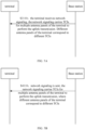
- Embodiments of a first aspect of the present disclosure provide a method for configuring an uplink transmission, including: for the uplink transmission, configuring different transmission configuration indications (TCI) for different antenna panels of a terminal.
- TCI transmission configuration indications
- Embodiments of a second aspect of the present disclosure provide an apparatus for configuring an uplink transmission, including: a processing module, configured to, for the uplink transmission, configure different TCIs for different antenna panels of a terminal.
- Embodiments of a third aspect of the present disclosure provide a communication device, including a processor, a transceiver, a memory, and an executable program stored in the memory and capable of being executed by the processor.
- the processor executes the executable program, the processor performs the method for configuring uplink transmission provided in the first aspect.
- Embodiments of a fourth aspect of the present disclosure provide a computer storage medium on which a computer program is stored.
- the computer program is executed by a processor, the method for configuring uplink transmission provided in the first aspect can be implemented.
- the multiple antenna panels of the terminal can simultaneously perform the uplink transmission, which can improve the throughput of a communication system and enhance transmission reliability
- first, second, third, etc. may be used to describe various information in the embodiments of the present disclosure, such information should not be limited to these terms. These terms are only used to distinguish the same type of information from each other.
- first information can also be called the second information, and similarly, the second information can also be called the first information.
- word “if” as used here can be interpreted as "when” or “while” or "in response to determining”.
- FIG. 1 it illustrates a block diagram of a wireless communication system provided by an embodiment of the present disclosure.
- the wireless communication system is a communication system based on cellular mobile communication technology.
- the wireless communication system may include several terminals 11 and several access devices 12.
- the terminal 11 may refer to a device that provides voice and/or data connectivity to a user.
- the terminal 11 can communicate with one or more core networks through a radio access network (RAN).
- RAN radio access network
- the terminal 11 may be an Internet-of- Things terminal, such as a sensor device, a mobile phone (also called as "cellular" phone) and a computer with an Internet-of- Things terminal, such as fixed, portable, pocket, handheld, computer built-in or vehicle-mounted devices, for example, a station (STA), a subscriber unit, a subscriber station, a mobile station, a mobile, a remote station, an access point, a remote terminal, an access terminal, a user terminal, a user agent, a user device, or a user equipment (UE).
- STA station
- UE user equipment
- the terminal 11 can also be a device of an unmanned aerial vehicle.
- the terminal 11 can also be a vehicle-mounted device, for example, an on-board computer with a wireless communication function, or a wireless communication device connected to an external on-board computer.
- the terminal 11 can also be a roadside device, for example, a streetlamp, a signal lamp or other roadside devices with wireless communication functions.
- the access device 12 may be a network device in the wireless communication system.
- the wireless communication system can be the fourth generation mobile communication (4G) system, also known as Long Term Evolution (LTE) system.
- 4G fourth generation mobile communication
- the wireless communication system can also be the fifth generation mobile communication (5G) system, also known as a new radio (NR) system or a 5G NR system.
- 5G fifth generation mobile communication
- NR new radio
- 5G NR new radio
- the wireless communication system can also be a next generation system of the 5G system.
- the access network in the 5G system can be called NG-RAN (new generation radio access network).
- the wireless communication system can also be a machine type communication (MTC) system.
- MTC machine type communication
- the access device 12 can be an evolutionary access device (eNB) used in the 4G system.
- the access device 12 can also be an access device (gNB) adopting a centralized and distributed architecture in the 5G system.
- the access device 12 adopts the centralized and distributed architecture it usually includes a central unit (CU) and at least two distri ubbed units (DU).
- the central unit is equipped with protocol stacks of a Packet Data Convergence Protocol (PDCP) layer, a Radio Link Control (RLC) layer and a Media Access Control (MAC) layer.
- the distribution unit is provided with a physical (PHY) layer protocol stack.
- PHY physical
- a wireless connection can be established between the access device 12 and the terminal 11 through a wireless radio.
- the wireless radio is a wireless radio based on the fourth generation mobile communication network technology (4G) standard.
- the wireless radio is a wireless radio based on the fifth generation mobile communication network technology (5G) standard.
- the wireless radio is a new radio.
- the wireless radio can also be a wireless radio based on a standard of the next generation mobile communication network technical of 5G.
- embodiments of the disclosure provide a method for configuring an uplink transmission, the method includes the followings.
- TCIs transmission configuration indications
- a communication device that configures different TCIs for different antenna panels of the terminal may be a base station.
- the terminal may include multiple antenna panels.
- the terminal may include two antenna panels, and the orientations of the two antenna panels of the terminal may be opposite.
- One antenna panel includes one or more antenna dipoles.
- a terminal has two antenna panels and can send data to transmission and reception point (TRP) 1 and TRP 2 of the base station simultaneously.
- TRP transmission and reception point
- the TCI here is information indicating a beam direction.
- Different antenna panels have different TCIs (that is, different antenna panels of the terminal are configured with separate TCI states), and beam directions of transmission beams of different antenna panels are individually indicated by their corresponding TCIs. In this way, different antenna panels of the terminal can be used to send uplink data and/or uplink signaling to different TRPs of the base station.
- the uplink transmission configuration of the terminal may further include at least one of the following:
- one or more of the above-mentioned transmission configurations may be sent by the base station to the terminal through one or more network signalings, or the above-mentioned uplink transmission configurations may be pre-agreed by a network protocol.
- the uplink transmission type includes but is not limited to:
- the multiple antenna panels of the terminal are each configured with corresponding TCI, the multiple antenna panels of the terminal can simultaneously perform the uplink transmission, which can improve the throughput of the communication system and enhance the transmission reliability.
- UCI uplink control information
- the PUCCH transmission can be divided into two categories from the perspective of bit number.
- One type is a PUCCH format used to carry 1 to 2-bit UCI transmission, and the other type is a PUCCH format used to carry more than 2-bit UCI transmission.
- the PUCCH transmission can also be divided into two categories. One is a PUCCH transmission in a short PUCCH format, which occupies 1 or 2 symbols for transmission, and the other one is a PUCCH transmission in a long PUCCH format, which occupies 4 to 14 symbols for transmission.
- the PUCCH format can be shown in Table 1: Table 1 PUCCH format number of symbols number of RBs User multiplexing capacity number of carried bits 0 1-2 1 12 ⁇ 2 1 4-14 1 12*OCC length ⁇ 2 2 1-2 1, 2, .. , 16 integer 0 >2 3 4-14 1, 2, 3, 4, 5, 6, 8, 9, 10, 12, 15, 16 0 >2 4 4-14 1 2 or 4 >2
- a number of repetitions at the slot level can be configured through a radio resource control (RRC) signaling nrofSlots, and repeated transmission can be performed in multiple consecutive slots on a same time-frequency resource. Repeated transmission is not supported for the PUCCH format 0/2.
- the supported number of repetitions is 1, 2, 4, and 8.
- Orthogonal cover code in Table 1.
- the uplink transmission type includes one of the following:
- the grant free uplink transmission includes but is not limited to at least one of the following:
- the grant free uplink transmission may include, but is not limited to, a configured grant (CG) uplink transmission.
- the grant free uplink transmission may include, but is not limited to, a CG-PUSCH transmission.
- the grant free CG-PUSCH may include but is not limited to: CG-PUSCH type 1 and CG PUSCH type 2.
- different TCIs are associated with different control resource pool indexes (CORESTPoolIndex). Different control resource pool indexes are associated with different TRPs of the base station.
- Different antenna panels of the terminal are associated with different TCIs, the TCIs are associated with the CORESTPoolIndex, and control resource pools indicated by the CORESTPoolIndex belong to different TRPs.
- the uplink transmission configuration from different antenna panels of the terminal to any TRP of the base station is realized.
- a control resource set is a set of downlink physical resource grids and a parameter set, and is used to carry DCI information.
- control resource set is located in a specific area of the frequency domain without occupying the full bandwidth.
- a CORESET P ⁇ 3 is configured for the terminal in each downlink bandwidth part (BWP).
- CORESET 0 is used for system information broadcasting and paging.
- a maximum of 3 control resource sets can be configured in a same downlink BWP.
- Each TRP must have one CORESET, except for CORESET 0, to schedule the PDSCH, indicate hybrid automatic repeat request response information (HARQ-ACK) to feed back a time domain resources used, and schedule the PUSCH.
- the remaining CORESET resources are used for public group configuration or beam failure recovery.
- ControlResourceSet contains two different CORESETPoolIndex values [0, 1] to distinguish which transmission point TRP the CORESET resource belongs to.
- the uplink transmission includes: a PUSCH transmission.
- One TCI is associated with one transport block (TB) of the PUSCH.
- the base station When the base station performs data transmission scheduling, it can schedule at TB granularity. Thus one TCI is associated with one TB of the PUSCH. In this way, different antenna panels of the terminal can be associated with different TBs or the same TB. Therefore, if different TCIs are associated with TBs of different PUSCHs, the terminal can realize simultaneous transmission of multiple TBs at one time, improving the data transmission efficiency of the base station.
- different TCIs are used for transmission of the same TB; or different TCIs are used for transmission of different TBs.
- multiple TCIs can be associated with the same TB.
- the base station may have more spatial and/or frequency diversity gain after receiving the TB, thus ensuring the transmission quality of the TB.
- Whether different TCIs are associated with the same TB or different TBs can be configured according to channel quality and uplink transmission quality of service (QoS) corresponding to the multiple TCIs of the terminal.
- QoS uplink transmission quality of service
- the uplink transmission includes: a PUCCH transmission.
- one TCI can be associated with one UCI, and different TCIs can be associated with the same or different UCIs.
- different TCIs are used for the transmission of a same UCI; or different TCIs are used for transmission of different UCIs.
- multiple antenna panels of the terminal can realize transmission of multiple UCIs at the same time, increasing the transmission rate. If different TCIs are associated with the same UCI, multiple antenna panels of the terminal can realize transmission of one UCI at the same time, which can improve the UCI transmission gain.
- one TCI is associated with one demodulation reference signal (DMRS) port combination of the terminal.
- DMRS port combination includes one or more DMRS ports of the terminal.
- the DMRS ports included in one DMRS port combination may be some or all ports of the terminal.
- the terminal has two antenna panels and includes 4 DMRS ports
- the TCIs corresponding to the two antenna panels are associated with the first, second, and fourth DMRS ports of the terminal.
- one TCI is associated with one data transmission layer set; one data transmission layer set includes: one or more data transmission layers.
- One TCI can be associated with one data transmission layer set, which can include one or more data transmission layers, for example, 1, 2, 3 or 4 data transmission layers.
- one data transmission layer set can include one or more data transmission layers, for example, 1, 2, 3 or 4 data transmission layers.
- time-frequency resources of different uplink transmissions do not overlap; or time-frequency resources of different uplink transmissions partially overlap; or time-frequency resources of different uplink transmissions completely overlap.
- time-frequency resources of different uplink transmissions do not overlap, it means that different PUSCH transmissions and/or PUCCH transmissions use completely different time-frequency domain resources, and there is no interference between them.
- time-frequency resources of different uplink transmissions may partially overlap, that is, part of the frequency domain resources of different uplink transmissions overlap, and/or part of the time domain resources of different uplink transmissions overlap, and some time-frequency domain resources do not overlap.
- At least two uplink transmissions use exactly the same time domain resources and use exactly the same frequency domain resources.
- different antenna panels of the terminal are configured with different TCIs, that is, different antenna panels of the terminal may use beams in different directions to perform the uplink transmission. In this way, even if the time-frequency domain resources of the uplink transmission partially or completely overlap, there is still little interference..
- multiple antenna panels of the terminal may use a NC-JT for the PUSCH transmission and/or PUCCH transmission.
- a number of layers for two antenna panels of the terminal to perform a PUSCH data transmission is 4 layers
- FIG. 4B shows the NC-JTs of the two antenna panels of the terminal to TRP1 and TRP2 respectively.
- a number of data transmission layers sent by the multiple antenna panels can be the same or different, and one data transmission layer does not need to be mapped to every antenna panel.
- the data transmission layer 1-2 is mapped to one antenna panel of the terminal
- the data transmission layer 3-4 is mapped to another antenna panel of the terminal.
- an uplink NC-JT is performed by using different code division multiplexing (CDM) groups in multiple DMRS ports associated with different TCIs; or,
- the CDM group is obtained by codeword encoding. If different encodings of orthogonal codewords are used, orthogonality between data can be achieved.
- DMRS ports with different CDM groups have different quasi-co-located QCL type D associations; or; DMRS ports with different CDM groups have a same QCL type D association.
- the quasi co-location means that large-scale parameters of a channel experienced by a symbol on a certain antenna port can be inferred from a channel experienced by a symbol on another DMRS port.
- the large-scale parameters may include delay spread, average delay, Doppler spread, Doppler shift, average gain, and a spatial reception parameter.
- the QCL of two DMRS ports in the sense of certain large-scale parameters means that these large-scale parameters of the two DMRS ports are the same. In other words, as long as certain large-scale parameters of the two DMRS ports are consistent, regardless of whether there are differences in their actual physical locations or corresponding antenna panel orientations, the terminal can determine that the two DMRS ports originate from the same location, i.e., quasi-co-located.
- the uplink NC-JT is performed using different antenna panels.
- the x th TCI indicates a beam direction of an x th antenna panel.
- a number of layers associated with the x th TCI is less than or equal to N-px; the N-px is a maximum number of data transmission layers supported by the x th antenna panel.
- the number of data transmission layers configured for an antenna panel of the terminal may be less than or equal to the maximum number of data transmission layers supported by the antenna panel.
- an uplink coherent joint transmission is performed by different antenna panels.
- the number of layers for the two antenna panels of the terminal to perform PUSCH data transmission is 4 layers
- FIG. 4 shows the C-JT of the two antenna panels of the terminal to TRP1 and TRP2 respectively.
- the numbers of the data transmission layers sent by the multiple antenna panels are the same, and each data transmission layer is transmitted.
- the spatial relationship information can be used to indicate the uplink beam directions of different antenna panels of the terminal.
- the indication information of the TCI has a TCI field; code points of the TCI field indicate TCIs corresponding to multiple antenna panels of the terminal.
- one code point in the TCI field corresponds to a combination of multiple TCIs.
- a sounding reference signal can be used to estimate a downlink channel and perform downlink beamforming. There may be a corresponding relationship between the SRI of the SRS and the direction of the uplink beam. Therefore, the SRI of the SRS is one type of TCI corresponding to different antenna panels of the terminal.
- the TCI is carried by at least one of the following signaling:
- the uplink transmission includes a PUSCH transmission
- a PUSCH type of the PUSCH transmission includes at least one of the following:
- the PUSCH is scheduled by multiple DCIs
- different DCIs may come from different TRPs of the base station.
- the state values (state) of N TCIs suitable for simultaneous transmission are configured for the terminal based on the unified TCI framework.
- the TCIs of different panels of the terminal can be indicated through N different joint TCIs.
- TCIs of the antenna panels during PUSCH transmission of the terminal can be jointly indicated through N separate UL TCIs.
- the antenna panel corresponds to TCI1
- the antenna panel corresponds to TCI2.
- Each TCI corresponds to the transmission/reception beam of one antenna panel of the terminal and faces one transmission TRP direction.
- Each TCI contains a different QCL Type-D source reference signal (QCL Type-D source RS), which may include at least one of the following:
- the terminal uses the antenna panel corresponding to the QCL Type-D source RS included in the TCI to perform transmission and reception.
- the spatial relationship information (spatialRelationInfo)1/2 indicated by the SRI combination is used.
- Embodiments of the present disclosure provide a solution for sending uplink data to multiple TRPs for multiple antenna panels.
- the details can be as follows.
- An NC-JT transmission of multiple transmission and reception points (MTRP) can be performed based on PUSCH transmission or PUCCH transmission scheduled with M-DCI scheduling through followings:
- the number of layers/layer sets corresponding to TCI1 may not be greater than N_p1, and the number of layers/layer sets corresponding to TCI2 may not be greater than N_p2.
- N_p1 is a maximum number of data transmission layers supported by antenna panel 1 of the terminal.
- N_p2 is a maximum number of data transmission layers supported by antenna panel 2 of the terminal.
- the time-frequency domain resources occupied by different PUSCH transmissions and/or PUCCH transmissions may not overlap, partially overlap, or completely overlap.
- the DMRS ports or port combinations of a PUSCH channel corresponding to different TCIs may come from the same CDM group according to a resource occupancy situation.
- the DMRS port groups corresponding to different TCIs may be the same or different, and the CDM groups corresponding to different TCIs may be the same or different.
- different TCIs correspond to different DMRS port groups, and correspond to different CDM groups.
- DMRS port groups corresponding to the same TCI can be allocated across CDM groups.
- DMRS ports cross CDM groups ports from different CDM groups belong to the same scheduling TRP as long as the QCL is the same.
- the C-JT transmission of uplink MTRP can be implemented through the following solutions: Applicable scenarios for the C-JT transmission of uplink MTRP: It is more suitable for devices such as Customer Premise Equipment (CPE) or a fixed wireless access (FWA) device.
- CPE Customer Premise Equipment
- FWA fixed wireless access
- Each TCI associated with different CORSETPoolIndex PUSCH schedules a same or different TBs, and is associated with its own set of layers/layer set and its corresponding set of DMRS ports or port combinations.
- Each TCI associated with different CORSETPoolIndex schedules the same or different UCI of the PUCCH, and associates the time-frequency domain resources corresponding to the respective PUCCHs and the respective DMRS ports.
- the number of layers/layer sets corresponding to TCI1 and TCI2 may not exceed min ⁇ N_p1,N_p2 ⁇ .
- the time-frequency domain resources occupied by different PUSCH transmissions do not overlap, the time-frequency domain resources partially overlap, or the time-frequency domain resources overlap completely.
- the DMRS ports or port combinations corresponding to different TCIs can come from the same CDM group or different CDM groups according to a resource occupancy situation.
- the DMRS port groups corresponding to different TCIs may be the same or different, and the CDM groups corresponding to different TCIs may be the same or different.
- the DMRS port groups corresponding to different TCIs are different and belong to different CDM groups.
- DMRS port groups corresponding to the same TCI can also be allocated across CDM groups.
- DMRS ports cross CDM groups ports from different CDM groups only need to have the same QCL.
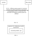
- embodiments of the present disclosure provides a method for configuring an uplink transmission, which may include: S3110, a terminal receives network signaling, the network signaling carries TCIs for multiple antenna panels of the terminal to perform the uplink transmission. Different antenna panels of the terminal correspond to different TCIs.
- the uplink transmission may be: synchronous transmission of the multiple antenna panels of the terminal.
- the uplink transmission includes one of the following:
- different TCIs are associated with different control resource pool indexes (CORESTPoolIndex), where different control resource pool indexes are associated with different transmission and reception points (TRP) of a base station.
- CORESTPoolIndex control resource pool indexes
- TRP transmission and reception points
- the uplink transmission includes: a PUSCH transmission.
- One TCI is associated with one transport block TB of the PUSCH.
- One TCI is associated with one transport block TB of the PUSCH.
- the uplink transmission includes: a PUCCH transmission.
- One TCI is associated with one UCI transmitted by the PUCCH.
- different TCIs are used for the transmission of the same UCI; or, different TCIs are used for the transmission of different UCIs.
- one TCI is associated with one DMRS port combination of the terminal.
- One DMRS port combination includes: one or more DMRS ports of the terminal.
- one TCI is associated with a data transmission layer set; one data transmission layer set includes: one or more data transmission layers.
- the time-frequency resources of different uplink transmissions do not overlap; or,
- an uplink NC-JT is performed by using different CDM groups in multiple DMRS ports associated with different TCIs; or,
- the DMRS ports with different CDM groups have different QCL type D associations; or; DMRS ports with different CDM groups have the same QCL type D association.
- the uplink non-coherent transmission NC-JT is performed using different antenna panels.
- an x th TCI indicates a beam direction of an x th antenna panel.
- the number of layers associated with the x th TCI is less than or equal to N-px; wherein the N-px is a maximum number of data transmission layers supported by the x th antenna panel.
- an uplink coherent joint transmission (C-JT) is performed by different antenna panels.
- the maximum number of data transmission layers associated with multiple TCIs is: min ⁇ N-p1, N-p2,...N-pX ⁇ ; where, the X is a total number of antenna panels of the terminal; the N-px is a maximum number of data transmission layers supported by an x th antenna panel; and the x is a positive integer less than or equal to X.
- the TCI includes one of the following:
- the TCI indication information includes multiple TCI fields.
- One TCI field indicates a TCI corresponding to one antenna panel of the terminal.
- indication information of the TCI has a TCI field.
- Code points of the TCI field indicate TCIs corresponding to multiple antenna panels of the terminal.
- the TCI is carried by at least one of the following signaling methods:
- the uplink transmission includes a PUSCH transmission
- a PUSCH type of the PUSCH transmission includes at least one of the following:
- embodiments of the present disclosure provides a method for configuring an uplink transmission, which may include: S4110, network signaling is sent, the network signaling carries TCIs for multiple antenna panels of the terminal to perform the uplink transmission, where different antenna panels of the terminal correspond to different TCIs.
- the uplink transmission may be: synchronous transmission of the multiple antenna panels of the terminal.
- the uplink transmission includes one of the following:
- different TCIs are associated with different control resource pool indexes (CORESTPoolIndex), where different control resource pool indexes are associated with different transmission and reception points (TRPs) of a base station.
- CORESTPoolIndex control resource pool indexes
- TRPs transmission and reception points
- the uplink transmission includes: a PUSCH transmission.
- One TCI is associated with one transport block TB of the PUSCH.
- One TCI is associated with one transport block TB of the PUSCH.
- different TCIs are used for the transmission of a same transport block TB; or, different TCIs are used for the transmission of different TBs.
- the uplink transmission includes: a PUCCH transmission.
- One TCI is associated with one UCI transmitted by the PUCCH.
- different TCIs are used for the transmission of the same UCI; or, different TCIs are used for the transmission of different UCIs.
- one TCI is associated with one DMRS port combination of the terminal.
- One DMRS port combination includes: one or more DMRS ports of the terminal.
- one TCI is associated with a data transmission layer set; one data transmission layer set includes: one or more data transmission layers.
- the time-frequency resources of different uplink transmissions do not overlap; or,
- an uplink NC-JT is performed by using different CDM groups in multiple DMRS ports associated with different TCIs; or,
- the DMRS ports with different CDM groups have different quasi-co-located QCL type D associations; or; DMRS ports with different CDM groups have the same QCL type D association.
- the uplink non-coherent transmission NC-JT is performed using different antenna panels.
- an x th TCI indicates a beam direction of an x th antenna panel.
- the number of layers associated with the x th TCI is less than or equal to N-px; wherein the N-px is a maximum number of data transmission layers supported by the x th antenna panel.
- an uplink coherent joint transmission (C-JT) is performed by different antenna panels.
- the maximum number of data transmission layers associated with multiple TCIs is: min ⁇ N-p1, N-p2,...N-pX ⁇ ; where, the X is a total number of antenna panels of the terminal; the N-px is a maximum number of data transmission layers supported by an x th antenna panel; and the x is a positive integer less than or equal to X.
- the TCI includes one of the following:
- the TCI indication information has multiple TCI fields
- One TCI field indicates a TCI corresponding to one antenna panel of the terminal.
- indication information of the TCI has a TCI field.
- Code points of the TCI field indicate TCIs corresponding to multiple antenna panels of the terminal.
- the TCI is carried by at least one of the following signaling methods:
- the uplink transmission includes a PUSCH transmission
- a PUSCH type of the PUSCH transmission includes at least one of the following:
- embodiments of the present disclosure provides a method for configuring an uplink transmission, which may include: S5110, different antenna panels of a terminal performs the uplink transmission using beams corresponding to TCIs, in which the TCIs associated with different antenna panels are different.
- a base station may receive the uplink transmission sent by the different antenna panels of the terminal according to the beams corresponding to the TCIs.
- the uplink transmission includes one of the following:
- different TCIs are associated with different control resource pool indexes (CORESTPoolIndex), where different control resource pool indexes are associated with different transmission and reception points (TRPs) of the base station.
- CORESTPoolIndex control resource pool indexes
- TRPs transmission and reception points
- the uplink transmission includes: a PUSCH transmission.
- One TCI is associated with one transport block TB of the PUSCH.
- One TCI is associated with one transport block TB of the PUSCH.
- different TCIs are used for the transmission of a same transport block TB; or, different TCIs are used for the transmission of different TBs.
- the uplink transmission includes: a PUCCH transmission.
- One TCI is associated with one UCI transmitted by the PUCCH.
- different TCIs are used for the transmission of the same UCI; or, different TCIs are used for the transmission of different UCIs.
- one TCI is associated with one DMRS port combination of the terminal.
- One DMRS port combination includes: one or more DMRS ports of the terminal.
- one TCI is associated with a data transmission layer set; one data transmission layer set includes: one or more data transmission layers.
- the time-frequency resources of different uplink transmissions do not overlap; or,
- an uplink NC-JT is performed by using different CDM groups in multiple DMRS ports associated with different TCIs; or,
- the DMRS ports with different CDM groups have different quasi-co-located QCL type D associations; or; DMRS ports with different CDM groups have the same QCL type D association.
- the uplink non-coherent transmission NC-JT is performed using different antenna panels.
- an x th TCI indicates a beam direction of an x th antenna panel.
- the number of layers associated with the x th TCI is less than or equal to N-px; wherein the N-px is a maximum number of data transmission layers supported by the x th antenna panel.
- an uplink coherent joint transmission (C-JT) is performed by different antenna panels.
- the maximum number of data transmission layers associated with multiple TCIs is: min ⁇ N-p1, N-p2,...N-pX ⁇ ; where, the X is a total number of antenna panels of the terminal; the N-px is a maximum number of data transmission layers supported by an x th antenna panel; and the x is a positive integer less than or equal to X.
- the TCI includes one of the following:
- the TCI indication information has multiple TCI fields.
- One TCI field indicates a TCI corresponding to one antenna panel of the terminal.
- indication information of the TCI has a TCI field.
- Code points of the TCI field indicate TCIs corresponding to multiple antenna panels of the terminal.
- the TCI is carried by at least one of the following signaling methods:
- the uplink transmission includes a PUSCH transmission
- a PUSCH type of the PUSCH transmission includes at least one of the following:
- embodiments of the present disclosure provides an apparatus for configuring an uplink transmission, which may include: a processing module, configured to, for the uplink transmission, configure different transmission configuration indications (TCIs) for different antenna panels of a terminal.
- a processing module configured to, for the uplink transmission, configure different transmission configuration indications (TCIs) for different antenna panels of a terminal.
- TCIs transmission configuration indications
- the apparatus for configuring an uplink transmission may include a base station.
- the apparatus for configuring an uplink transmission may include antenna panels for transmitting the TCIs.
- the uplink transmission includes one of the following:
- different TCIs are associated with different control resource pool indexes (CORESTPoolIndex), where different control resource pool indexes are associated with different transmission and reception points (TRPs) of the base station.
- CORESTPoolIndex control resource pool indexes
- TRPs transmission and reception points
- the uplink transmission includes: a PUSCH transmission.
- One TCI is associated with one transport block TB of the PUSCH transmission.
- different TCIs are used for the transmission of the same transport block TB; or, Different TCIs are used for the transmission of different TBs.
- the uplink transmission includes: a PUCCH transmission.
- One TCI is associated with one UCI transmitted by the PUCCH.
- different TCIs are used for the transmission of the same UCI; or, Different TCIs are used for the transmission of different UCIs.
- one TCI is associated with one DMRS port combination of the terminal.
- One DMRS port combination includes: one or more DMRS ports of the terminal.
- one TCI is associated with a data transmission layer set; one data transmission layer set includes: one or more data transmission layers.
- an uplink NC-JT is performed by using different CDM groups in multiple DMRS ports associated with different TCIs; or,
- the DMRS ports with different CDM groups have different quasi-co-located QCL type D associations; or; DMRS ports with different CDM groups have the same QCL type D association.
- an x th TCI indicates a beam direction of an x th antenna panel.
- the number of layers associated with the x th TCI is less than or equal to N-px; wherein the N-px is a maximum number of data transmission layers supported by the x th antenna panel.
- an uplink coherent joint transmission is performed by different antenna panels.
- the maximum number of data transmission layers associated with multiple TCIs is: min ⁇ N-p1, N-p2,...N-pX ⁇ ; where, the X is a total number of antenna panels of the terminal; the N-px is a maximum number of data transmission layers supported by an x th antenna panel; and the x is a positive integer less than or equal to X.
- the TCI includes one of the following:
- the TCI indication information has multiple TCI fields.
- One TCI field indicates a TCI corresponding to one antenna panel of the terminal.
- the TCI indication information has a TCI field; Code points of the TCI field indicate TCIs corresponding to multiple antenna panels of the terminal.
- the TCI is carried by at least one of the following signaling methods:
- Embodiments of the present disclosure provide a communication device, including:
- the processor is configured to execute the method for configuring an uplink transmission provided by any of the foregoing technical solutions.
- the processor may include various types of storage media, which are non-transitory computer storage media that can continue to store information stored thereon after the communication device is powered off.
- the processor may be connected to the memory through a bus or the like, to read the executable program stored on the memory, such as at least one of the methods shown in FIG. 2 and FIG. 5A to FIG. 5C .
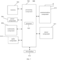
- the processing component 802 generally controls the whole operation of the terminal 800, such as the operations related to display, phone call, data communication, camera operation and recording operation.
- the processing component 802 may include one or more processors 820 to perform instructions, to complete all or part of steps of the above method.
- the processing component 802 may include one or more modules for the convenience of interaction between the processing component 802 and other components.
- the processing component 802 may include a multimedia module for the convenience of interaction between the multimedia component 808 and the processing component 802.
- the memory 804 is configured to store various types of data to support the operation of the terminal 800. Examples of the data include the instructions of any applications or methods operated on the terminal 800, contact data, phone book data, messages, pictures, videos, etc.
- the memory 804 may be implemented by any type of temporary or non-temporary storage devices or their combination, such as a static random access memory (SRAM), an electrically erasable programmable read-only memory (EEPROM), an electrically programmable read-only memory (EPROM), a programmable read-only memory (PROM), a read-only memory (ROM), a magnetic memory, a flash memory, a magnetic disk or an optical disk.
- SRAM static random access memory
- EEPROM electrically erasable programmable read-only memory
- EPROM electrically programmable read-only memory
- PROM programmable read-only memory
- ROM read-only memory
- the power supply component 806 may provide power for all components of the terminal 800.
- the power supply component 806 may include a power supply management system, one or more power supplies, and other units related to generating, managing and distributing power for the terminal 800.
- the multimedia component 808 includes a screen provided an output interface between the terminal 800 and the user.
- the screen may include a liquid crystal display (LCD) and a touch panel (TP).
- TP touch panel
- the screen may be implemented as a touch screen to receive an input signal from the user.
- the touch panel includes one or more touch sensors to sense touching, sliding and gestures on the touch panel. The touch sensor may not only sense the boundary of a touch or slide action, but also detect the duration and pressure related to the touch or slide operation.
- the multimedia component 808 includes a front camera and/or a rear camera. When the terminal 800 is in an operation mode, such as a shooting mode or a video mode, the front camera or the rear camera may receive the external multimedia data.
- Each front camera and rear camera may be a fixed optical lens system or an optical lens system with a focal length and an optical zoom capacity.
- the audio component 810 is configured to output and/or input an audio signal.
- the audio component 810 includes a microphone (MIC).
- the microphone When the terminal 800 is in an operation mode, such as a call mode, a record mode, and a speech recognition mode, the microphone is configured to receive an external audio signal.
- the received audio signal may be further stored in the memory 804 or sent via the communication component 816.
- the audio component 810 further includes a speaker configured to output an audio signal.
- the I/O interface 812 provides an interface for the processing component 802 and the peripheral interface module, and the peripheral interface module may be a keyboard, a click wheel, a button, etc.
- the button may include is but not limited to a home button, a volume button, a start button and a lock button.
- the sensor component 814 includes one or more sensors, configured to provide various aspects of status assessment for the terminal 800.
- the sensor component 814 may detect the on/off state of the terminal 800 and the relative positioning of the component.
- the component is a display and a keypad of the terminal 800.
- the sensor component 814 may further detect the location change of the terminal 800 or one component of the terminal 800, the presence or absence of contact between the user and the terminal 800, the orientation or acceleration/deceleration of the terminal 800, and the temperature change of the terminal 800.
- the sensor component 814 may include a proximity sensor configured to detect the existence of the objects nearby without any physical contact.
- the sensor component 814 may further include a light sensor such as a complementary metal oxide semiconductor (CMOS) or a charge-coupled device (CCD) image sensor, which is configured to use in imaging applications.
- CMOS complementary metal oxide semiconductor
- CCD charge-coupled device
- the sensor component 814 may further include an acceleration transducer, a gyroscope sensor, a magnetic sensor, a pressure sensor or a temperature sensor.
- the communication component 816 is configured for the convenience of wire or wireless communication between the terminal 800 and other devices.
- the terminal 800 may access wireless networks based on communication standard, such as Wi-Fi, 2G or 3G, or their combination.
- the communication component 816 receives broadcast signals or broadcast-related information from an external broadcast management system via a broadcast channel.
- the communication component 816 further includes a near field communication (NFC) module to facilitate short-range communication.
- NFC near field communication
- the NFC module may be achieved based on a radio frequency identification (RFID) technology, an infrared data association (IrDA) technology, an ultra-wide band (UWB) technology, a blue tooth (BT) technology and other technologies.
- RFID radio frequency identification
- IrDA infrared data association
- UWB ultra-wide band
- BT blue tooth
- the terminal 800 may be implemented by one or more application specific integrated circuits (ASIC), digital signal processors (DSP), digital signal processing devices (DSPD), programmable logic devices (PLD), field programmable gate arrays (FPGA), controllers, microcontrollers, microprocessors or other electronics components, which is configured to perform the above methods.
- ASIC application specific integrated circuits
- DSP digital signal processors
- DSPD digital signal processing devices
- PLD programmable logic devices
- FPGA field programmable gate arrays
- controllers microcontrollers, microprocessors or other electronics components, which is configured to perform the above methods.
- a non-transitory computer-readable storage medium which includes instructions, such as the memory 804 including instructions, the instructions may be executed by the processor 820 of the terminal 800 to complete the above methods.
- the non-transitory computer-readable storage medium may be a ROM, a random access memory (RAM), a CD-ROM, a magnetic tape, a floppy disk, an optical data storage device, etc.
- embodiments of the present disclosure shows a structure of a communication device 900.
- the communication device 900 may be provided as a network device.
- the communication device 900 may be the aforementioned base station.
- the communications device 900 includes a processing component 922, which further includes one or more processors, and memory resources represented by a memory 932 for storing instructions, such as application programs, executable by the processing component 922.
- the application program stored in memory 932 may include one or more modules, each corresponding to a set of instructions.
- the processing component 922 is configured to execute instructions to perform any method performed by the above-mentioned method on the base station, for example, at least one of the methods shown in FIG. 2 and FIG. 5A to FIG. 5C .
- the communication device 900 may also include a power supply component 926 configured to perform power management of the communication device 900, a wired or wireless network interface 950 configured to connect the communication device 900 to a network, and an input-output (I/O) interface 958.
- the communications device 900 may operate based on an operating system stored in the memory 932, such as Windows Server TM , Mac OS X TM , Unix TM , Linux TM , FreeBSD TM or the like.
Landscapes
- Engineering & Computer Science (AREA)
- Signal Processing (AREA)
- Computer Networks & Wireless Communication (AREA)
- Mobile Radio Communication Systems (AREA)
- Telephone Function (AREA)
Applications Claiming Priority (1)
| Application Number | Priority Date | Filing Date | Title |
|---|---|---|---|
| PCT/CN2022/090093 WO2023206301A1 (zh) | 2022-04-28 | 2022-04-28 | 上行传输配置方法及装置、通信设备及存储介质 |
Publications (2)
| Publication Number | Publication Date |
|---|---|
| EP4518477A1 true EP4518477A1 (de) | 2025-03-05 |
| EP4518477A4 EP4518477A4 (de) | 2025-07-30 |
Family
ID=88516879
Family Applications (1)
| Application Number | Title | Priority Date | Filing Date |
|---|---|---|---|
| EP22939151.1A Pending EP4518477A4 (de) | 2022-04-28 | 2022-04-28 | Verfahren und vorrichtung zur konfiguration von uplink-übertragungen, kommunikationsvorrichtung und speichermedium |
Country Status (4)
| Country | Link |
|---|---|
| US (1) | US20250261198A1 (de) |
| EP (1) | EP4518477A4 (de) |
| CN (1) | CN117322100A (de) |
| WO (1) | WO2023206301A1 (de) |
Families Citing this family (2)
| Publication number | Priority date | Publication date | Assignee | Title |
|---|---|---|---|---|
| WO2024016204A1 (en) * | 2022-07-20 | 2024-01-25 | Qualcomm Incorporated | Tci for custom non-codebook-based beams |
| WO2025166711A1 (zh) * | 2024-02-08 | 2025-08-14 | Oppo广东移动通信有限公司 | 无线通信方法、终端设备以及网络设备 |
Family Cites Families (8)
| Publication number | Priority date | Publication date | Assignee | Title |
|---|---|---|---|---|
| WO2021003620A1 (zh) * | 2019-07-05 | 2021-01-14 | Oppo广东移动通信有限公司 | 下行信号传输的方法和设备 |
| CN115553029B (zh) * | 2020-05-13 | 2025-06-17 | 高通股份有限公司 | 用于多个天线面板传输的多个上行链路配置 |
| WO2022006833A1 (en) * | 2020-07-10 | 2022-01-13 | Qualcomm Incorporated | Uplink control information multiplexing for multiple panels |
| CN113973369B (zh) * | 2020-07-22 | 2026-03-06 | 维沃移动通信有限公司 | 获取、指示通信资源的方法、装置及电子设备 |
| WO2022020694A1 (en) * | 2020-07-24 | 2022-01-27 | Comcast Cable Communications, Llc | Transmission repetition for wireless communication |
| US20230232415A1 (en) * | 2020-07-29 | 2023-07-20 | Lg Electronics Inc. | Method and apparatus for uplink transmission and reception in wireless communication system |
| KR102575694B1 (ko) * | 2020-08-07 | 2023-09-06 | 엘지전자 주식회사 | 무선 통신 시스템에서 상향링크 송수신 방법 및 장치 |
| WO2022141074A1 (zh) * | 2020-12-29 | 2022-07-07 | 北京小米移动软件有限公司 | 波束指示方法、波束指示装置及存储介质 |
-
2022
- 2022-04-28 WO PCT/CN2022/090093 patent/WO2023206301A1/zh not_active Ceased
- 2022-04-28 CN CN202280001515.6A patent/CN117322100A/zh active Pending
- 2022-04-28 EP EP22939151.1A patent/EP4518477A4/de active Pending
- 2022-04-28 US US18/859,635 patent/US20250261198A1/en active Pending
Also Published As
| Publication number | Publication date |
|---|---|
| US20250261198A1 (en) | 2025-08-14 |
| CN117322100A (zh) | 2023-12-29 |
| WO2023206301A1 (zh) | 2023-11-02 |
| EP4518477A4 (de) | 2025-07-30 |
Similar Documents
| Publication | Publication Date | Title |
|---|---|---|
| US9497682B2 (en) | Central processing unit and methods for supporting coordinated multipoint transmission in an LTE network | |
| WO2021237721A1 (zh) | Harq-ack码本的反馈方法和终端设备 | |
| WO2021237702A1 (zh) | Harq-ack码本的反馈方法和终端设备 | |
| EP4319422A1 (de) | Kommunikationsverfahren und -vorrichtung für pusch und speichermedium | |
| JP2015503869A (ja) | アップリンクでの制御信号に関する通信リソース割当 | |
| EP4518477A1 (de) | Verfahren und vorrichtung zur konfiguration von uplink-übertragungen, kommunikationsvorrichtung und speichermedium | |
| US20240284413A1 (en) | Communication method, apparatus, and system | |
| JP2023514730A (ja) | フィードバックリソース決定方法およびフィードバックリソース決定装置 | |
| CN117642998A (zh) | 无线通信的方法和终端 | |
| EP4518481A1 (de) | Informationsverarbeitungsverfahren und -vorrichtung sowie endgerät, basisstation und speichermedium | |
| US12495425B2 (en) | Method for physical channel transmission, and corresponding terminal device and communication device | |
| WO2021227142A1 (zh) | Harq-ack码本的反馈方法、终端设备和网络设备 | |
| US20240163020A1 (en) | Communication method and storage medium | |
| EP4518482A1 (de) | Verfahren und vorrichtung zur übertragung eines physikalischen uplink-steuerkanals (pucch), kommunikationsvorrichtung und speichermedium | |
| JP7778966B2 (ja) | 物理アップリンク共有チャネル設定方法、装置、通信デバイス及び記憶媒体 | |
| EP4572450A1 (de) | Vorcodierungsanzeigeverfahren und -vorrichtung sowie speichermedium | |
| US20250294564A1 (en) | Physical uplink control channel transmission method and apparatus, communication device, and storage medium | |
| US20250324406A1 (en) | Frequency-domain resource determination method and apparatus, and communication device and storage medium | |
| RU2847602C2 (ru) | Способ и устройство для конфигурирования физического совместно используемого канала восходящей линии связи, устройство связи и носитель данных | |
| EP4518215B1 (de) | Verfahren und vorrichtung zur konfiguration eines gemeinsam genutzten physikalischen uplink-kanals, kommunikationsvorrichtung und speichermedium | |
| WO2021088063A1 (zh) | 一种通信方法及装置 | |
| EP4668638A1 (de) | Verfahren und vorrichtung zur kommunikation über einen gemeinsam genutzten physikalischen uplink-kanal (pusch) und speichermedium | |
| WO2023206290A1 (zh) | Pusch传输配置方法及装置、通信设备及存储介质 | |
| CN120130036A (zh) | 无线通信的方法及装置 | |
| CN117730595A (zh) | 无线通信的方法和通信设备 |
Legal Events
| Date | Code | Title | Description |
|---|---|---|---|
| STAA | Information on the status of an ep patent application or granted ep patent |
Free format text: STATUS: THE INTERNATIONAL PUBLICATION HAS BEEN MADE |
|
| PUAI | Public reference made under article 153(3) epc to a published international application that has entered the european phase |
Free format text: ORIGINAL CODE: 0009012 |
|
| STAA | Information on the status of an ep patent application or granted ep patent |
Free format text: STATUS: REQUEST FOR EXAMINATION WAS MADE |
|
| 17P | Request for examination filed |
Effective date: 20241126 |
|
| AK | Designated contracting states |
Kind code of ref document: A1 Designated state(s): AL AT BE BG CH CY CZ DE DK EE ES FI FR GB GR HR HU IE IS IT LI LT LU LV MC MK MT NL NO PL PT RO RS SE SI SK SM TR |
|
| A4 | Supplementary search report drawn up and despatched |
Effective date: 20250630 |
|
| RIC1 | Information provided on ipc code assigned before grant |
Ipc: H04W 72/04 20230101AFI20250624BHEP Ipc: H04L 5/00 20060101ALI20250624BHEP |
|
| DAV | Request for validation of the european patent (deleted) | ||
| DAX | Request for extension of the european patent (deleted) |