EP4518481A1 - Informationsverarbeitungsverfahren und -vorrichtung sowie endgerät, basisstation und speichermedium - Google Patents
Informationsverarbeitungsverfahren und -vorrichtung sowie endgerät, basisstation und speichermedium Download PDFInfo
- Publication number
- EP4518481A1 EP4518481A1 EP22939403.6A EP22939403A EP4518481A1 EP 4518481 A1 EP4518481 A1 EP 4518481A1 EP 22939403 A EP22939403 A EP 22939403A EP 4518481 A1 EP4518481 A1 EP 4518481A1
- Authority
- EP
- European Patent Office
- Prior art keywords
- transmission
- tci
- terminal
- pucch
- tcis
- Prior art date
- Legal status (The legal status is an assumption and is not a legal conclusion. Google has not performed a legal analysis and makes no representation as to the accuracy of the status listed.)
- Pending
Links
Images


Classifications
-
- H—ELECTRICITY
- H04—ELECTRIC COMMUNICATION TECHNIQUE
- H04L—TRANSMISSION OF DIGITAL INFORMATION, e.g. TELEGRAPHIC COMMUNICATION
- H04L1/00—Arrangements for detecting or preventing errors in the information received
- H04L1/08—Arrangements for detecting or preventing errors in the information received by repeating transmission, e.g. Verdan system
-
- H—ELECTRICITY
- H04—ELECTRIC COMMUNICATION TECHNIQUE
- H04W—WIRELESS COMMUNICATION NETWORKS
- H04W72/00—Local resource management
- H04W72/20—Control channels or signalling for resource management
- H04W72/21—Control channels or signalling for resource management in the uplink direction of a wireless link, i.e. towards the network
-
- H—ELECTRICITY
- H04—ELECTRIC COMMUNICATION TECHNIQUE
- H04B—TRANSMISSION
- H04B7/00—Radio transmission systems, i.e. using radiation field
- H04B7/02—Diversity systems; Multi-antenna system, i.e. transmission or reception using multiple antennas
- H04B7/022—Site diversity; Macro-diversity
- H04B7/024—Co-operative use of antennas of several sites, e.g. in co-ordinated multipoint or co-operative multiple-input multiple-output [MIMO] systems
-
- H—ELECTRICITY
- H04—ELECTRIC COMMUNICATION TECHNIQUE
- H04B—TRANSMISSION
- H04B7/00—Radio transmission systems, i.e. using radiation field
- H04B7/02—Diversity systems; Multi-antenna system, i.e. transmission or reception using multiple antennas
- H04B7/04—Diversity systems; Multi-antenna system, i.e. transmission or reception using multiple antennas using two or more spaced independent antennas
- H04B7/06—Diversity systems; Multi-antenna system, i.e. transmission or reception using multiple antennas using two or more spaced independent antennas at the transmitting station
- H04B7/0613—Diversity systems; Multi-antenna system, i.e. transmission or reception using multiple antennas using two or more spaced independent antennas at the transmitting station using simultaneous transmission
- H04B7/0615—Diversity systems; Multi-antenna system, i.e. transmission or reception using multiple antennas using two or more spaced independent antennas at the transmitting station using simultaneous transmission of weighted versions of same signal
- H04B7/0619—Diversity systems; Multi-antenna system, i.e. transmission or reception using multiple antennas using two or more spaced independent antennas at the transmitting station using simultaneous transmission of weighted versions of same signal using feedback from receiving side
- H04B7/0636—Feedback format
- H04B7/0639—Using selective indices, e.g. of a codebook, e.g. pre-distortion matrix index [PMI] or for beam selection
-
- H—ELECTRICITY
- H04—ELECTRIC COMMUNICATION TECHNIQUE
- H04L—TRANSMISSION OF DIGITAL INFORMATION, e.g. TELEGRAPHIC COMMUNICATION
- H04L5/00—Arrangements affording multiple use of the transmission path
-
- H—ELECTRICITY
- H04—ELECTRIC COMMUNICATION TECHNIQUE
- H04L—TRANSMISSION OF DIGITAL INFORMATION, e.g. TELEGRAPHIC COMMUNICATION
- H04L5/00—Arrangements affording multiple use of the transmission path
- H04L5/003—Arrangements for allocating sub-channels of the transmission path
- H04L5/0048—Allocation of pilot signals, i.e. of signals known to the receiver
-
- H—ELECTRICITY
- H04—ELECTRIC COMMUNICATION TECHNIQUE
- H04L—TRANSMISSION OF DIGITAL INFORMATION, e.g. TELEGRAPHIC COMMUNICATION
- H04L5/00—Arrangements affording multiple use of the transmission path
- H04L5/003—Arrangements for allocating sub-channels of the transmission path
- H04L5/0053—Allocation of signalling, i.e. of overhead other than pilot signals
-
- H—ELECTRICITY
- H04—ELECTRIC COMMUNICATION TECHNIQUE
- H04L—TRANSMISSION OF DIGITAL INFORMATION, e.g. TELEGRAPHIC COMMUNICATION
- H04L5/00—Arrangements affording multiple use of the transmission path
- H04L5/0091—Signalling for the administration of the divided path, e.g. signalling of configuration information
- H04L5/0094—Indication of how sub-channels of the path are allocated
Definitions
- the present disclosure relates to the field of wireless communication technologies but is not limited to the field of wireless communication technologies, and particularly relates to a method and an apparatus for processing information, a terminal, a base station and a storage medium.
- the present disclosure relates to the field of wireless communication technologies but is not limited to the field of wireless communication technologies, and particularly relates to a method and an apparatus for processing information, a terminal, a base station and a storage medium.
- NR new radio
- network deployment with a large number of distributed access points and centralized baseband processing will be more conducive to providing a balanced user experience rate, and significantly reduce a delay and signaling overhead caused by handover.
- TRP transmission reception point
- Panels or TRPs can also be connected by an optical fiber for more flexible distributed deployment.
- cooperation between multi-TRP or multi-panel can also be used to transmit/receive multiple beams from multiple angles, thereby reducing the impact caused by the blocking effect.
- uplink control information (UCI) and other information sent by a terminal to a base station can be carried on a physical uplink control channel (PUCCH).
- PUCCH physical uplink control channel
- the base station is required to configure beam indication information of the PUCCH for the terminal.
- Embodiments of the present disclosure provide a method and an apparatus for processing information, a terminal, a base station and a storage medium.
- a first aspect of embodiments of the present disclosure provides a method for processing information.
- the method is performed by a base station, and includes: sending a network signaling to a terminal, in which the network signaling includes beam indication information configured for a physical uplink control channel (PUCCH) resource indicated by a PUCCH resource indicator (PRI), the beam indication information includes multiple transmission configuration indications (TCIs), and the beam indication information is used by the terminal to perform joint transmission for PUCCHs based on a spatial division multiplexing (SDM) mode of multi-panel or multi-transmission reception point (TRP).
- PUCCH physical uplink control channel
- PRI PUCCH resource indicator
- TCIs transmission configuration indications
- SDM spatial division multiplexing
- a second aspect of embodiments of the present disclosure provides a method for processing information.
- the method is performed by a terminal, and includes: receiving a network signaling sent by a base station, in which the network signaling includes beam indication information configured for a physical uplink control channel (PUCCH) resource indicated by a PUCCH resource indicator (PRI), the beam indication information includes multiple transmission configuration indications (TCIs), and the beam indication information is used by the terminal to perform joint transmission for PUCCHs based on a spatial division multiplexing (SDM) mode of multi-panel or multi-transmission reception point (TRP).
- PUCCH physical uplink control channel
- PRI PUCCH resource indicator
- TCIs transmission configuration indications
- SDM spatial division multiplexing
- a third aspect of embodiment of the present disclosure provides an apparatus for processing information.
- the apparatus is applied to a base station, and includes: a sending module, configured to send a network signaling to a terminal, wherein the network signaling comprises beam indication information configured for a physical uplink control channel (PUCCH) resource indicated by a PUCCH resource indicator (PRI), the beam indication information comprises multiple transmission configuration indications (TCIs), and the beam indication information is used by the terminal to perform joint transmission for PUCCHs based on a spatial division multiplexing (SDM) mode of multi-panel or multi-transmission reception point (TRP).
- PUCCH physical uplink control channel
- PRI PUCCH resource indicator
- TCIs transmission configuration indications
- SDM spatial division multiplexing
- a fourth aspect of embodiments of the present disclosure provides an apparatus for processing information.
- the apparatus is applied to a terminal, and includes: a receiving module, configured to receive a network signaling sent by a base station, wherein the network signaling comprises beam indication information configured for a physical uplink control channel (PUCCH) resource indicated by a PUCCH resource indicator (PRI), the beam indication information comprises multiple transmission configuration indications (TCIs), and the beam indication information is used by the terminal to perform joint transmission for PUCCHs based on a spatial division multiplexing (SDM) mode of multi-panel or multi-transmission reception point (TRP).
- PUCCH physical uplink control channel
- PRI PUCCH resource indicator
- TCIs transmission configuration indications
- SDM spatial division multiplexing
- a fifth aspect of embodiments of the present disclosure provides a base station.
- the base station includes a processor, a memory, and an executable program stored on the memory and capable of being run by the processor.
- the processor runs the executable program, it executes the method for processing information provided by the aforementioned first aspect.
- a sixth aspect of embodiments of the present disclosure provides a terminal.
- the terminal includes a processor, a memory, and an executable program stored in the memory and capable of being run by the processor.
- the processor runs the executable program, it executes the method for processing information provided by the aforementioned second aspect.
- a seventh aspect of the embodiments of the present disclosure provides a computer storage medium storing an executable program.
- the executable program is executed by a processor, the method for processing information provided by the first aspect or the second aspect can be implemented.
- the network signaling sent to the terminal since the network signaling sent to the terminal includes the beam indication information configured for a PUCCH resource indicated by the PRI, and the beam indication information includes multiple TCIs used by the terminal to perform joint transmission for the PUCCHs based on the SDM mode of the multi-panel/multi-TRP, so that multi-panel of the terminal can perform PUCCH transmission at the same time, thereby improving the throughput of the communication system and improving transmission reliability.
- first, second, third, etc. may be used to describe various information in the embodiments of the present disclosure, the information should not be limited to these terms. These terms are only used to distinguish information of the same type from each other.
- first information may also be called second information, and similarly, the second information may also be called first information.
- word “if” as used herein may be interpreted as “when” or “in a case that” or “in response to determining that”.
- FIG. 1 shows a schematic structural diagram of a wireless communication system provided by an embodiment of the present disclosure.
- the wireless communication system is a communication system based on cellular mobile communication technology.
- the wireless communication system may include several terminals 11 and several base stations 12.
- the terminal 11 may be a device that provides voice and/or data connectivity to a user.
- the terminal 11 may communicate with one or more core networks via a radio access network (RAN).
- RAN radio access network
- the terminal 11 may be an Internet of Things terminal, such as a sensor device, a mobile phone (or a "cellular" phone) and a computer with the Internet of Things terminal, for example, which can be a fixed, portable, pocket-sized, handheld, computer-built-in or vehicle-mounted device.
- a station STA
- subscriber unit subscriber station, mobile station, mobile, remote station, access point, remote terminal, access terminal, user terminal, user agent, user device, or user equipment (UE).
- the terminal 11 may be a device of an unmanned aerial vehicle.
- the base station 12 may be an evolved access device (eNB) used in the 4G system.
- the base station 12 may also be an access device (gNB) using a centralized distributed architecture in the 5G system.
- eNB evolved access device
- gNB access device
- the centralized unit is provided with a protocol stack including a packet data convergence protocol (PDCP) layer, a radio link control protocol (RLC) layer, and a media access control (MAC) layer.
- PDCP packet data convergence protocol
- RLC radio link control protocol
- MAC media access control
- the distributed unit is provided with a physical (PHY) layer protocol stack.
- PHY physical
- an E2E (End to End) or D2D (device to device) connection can also be established between the terminals 11, for example, V2V (vehicle to vehicle) communication, V2I (vehicle to Infrastructure) communication, V2P (vehicle to pedestrian) communication, and other scenes in the vehicle to everything (V2X) communication.
- V2V vehicle to vehicle
- V2I vehicle to Infrastructure
- V2P vehicle to pedestrian
- V2X vehicle to everything
- the one or more terminals When a connection is established between terminals, if one or more terminals function as a base station in the communication between terminals, the one or more terminals can also be regarded as the above-mentioned base station 12, and the other terminals can be regarded as the above-mentioned terminal 11.
- the vehicle-mounted terminal A reports its capability information (such as antenna capability information) to another vehicle-mounted terminal B, and the vehicle-mounted terminal B controls the communication between the vehicle-mounted terminal A and the vehicle-mounted terminal B based on its capability information. That is, the vehicle-mounted terminal B acts as a leading vehicle in the vehicle network.
- the vehicle-mounted terminal B can be regarded as the above-mentioned base station 12, and the vehicle-mounted terminal A can be regarded as the above-mentioned terminal 11.
- the above wireless communication system may also include a network management device 13.
- the several base stations 12 are connected to the network management device 13, respectively.
- the network management device 13 may be a core network device in the wireless communication system.
- the network management device 13 may be a mobility management entity (MME) in an evolved packet core (EPC).
- the network management device can also be other core network devices, such as a serving gateway (SGW), a public data network gateway (PGW), a policy and charging rules function (PCRF), or a home subscriber server (HSS), etc.
- SGW serving gateway
- PGW public data network gateway
- PCRF policy and charging rules function
- HSS home subscriber server
- FIG. 2 is a schematic flow chart of a method for processing information according to an exemplary embodiment.
- the method for processing information can be applied to the base station in the wireless communication system shown in FIG. 1 .
- the method may include the following steps.
- a network signaling is sent to a terminal, in which the network signaling includes beam indication information configured for a PUCCH resource indicated by a PRI, the beam indication information includes multiple TCIs, and the beam indication information is used by the terminal to perform non-coherent joint transmission (NC-JT) of a PUCCH based on multi-panel or a SDM mode of multi-TRP.
- the network signaling includes beam indication information configured for a PUCCH resource indicated by a PRI
- the beam indication information includes multiple TCIs
- the beam indication information is used by the terminal to perform non-coherent joint transmission (NC-JT) of a PUCCH based on multi-panel or a SDM mode of multi-TRP.
- NC-JT non-coherent joint transmission
- each data stream involved in the joint PUCCH transmission is only mapped to a part of the TRPs.
- a terminal may have multiple panels, and the multiple panels of the terminal may point to different beam directions at the same time.
- the terminal may send uplink data and/or uplink signaling to the base station through transmission beams on different panels, for example, sending the PUCCH; the terminal may also receive downlink data and/or downlink signaling sent by the base station through reception beams on different panels.
- the sending/reception beams of different panels of the terminal may be directed to different TRPs of the base station.
- Each TRP of the base station may include one or more panels, or may be a device in the access network that communicates with the terminal through one or more sectors on the air interface, etc.
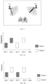
- a terminal includes two panels, and directions of the two panels of the terminal may be opposite.
- One of the panels includes one or more antenna elements.
- a terminal has two panels and may simultaneously send uplink data to TRP1 and TRP2 of the base station.
- the base station may use one or more TRPs to send the network signaling to the terminal, in which the network signaling includes at least one of: downlink control information (DCI), media access control (MAC) control element (CE), radio resource control (RRC) signaling.
- DCI downlink control information
- MAC media access control
- CE radio resource control
- RRC radio resource control
- each TRP of the base station may use its own physical downlink control channel (PDCCH) to send the DCI signaling to the terminal.
- the DCI signaling includes beam indication information configured for a PUCCH resource indicated by a PRI.
- the beam indication information includes TCI1 corresponding to panel 1 of the terminal and TCI2 corresponding to panel 2 of the terminal.
- Different TCIs may indicate the transmission beam directions of different panels of the terminal or beam directions for PUCCH transmission towards multiple different TRPs of the base station, so that the terminal may perform the joint PUCCH transmission based on SDM mode through the multiple different panels at the same time.
- the beam indication information configured for a PUCCH resource indicated by the PRI may also be indicated through a MAC CE signaling.
- the beam indication information may include a TCI state corresponding to a specified codepoint, and different TCI states indicate uplink beam directions of different panels of the terminal.
- the beam indication information configured for a PUCCH resource indicated by the PRI may also be indicated through an RRC signaling.
- RRC signaling For each PUCCH resource, multiple pieces of spatial relation information of the PUCCH resource (PUCCH-SpatialRelationInfo) may be configured in the RRC signaling, and then the PUCCH-SpatialRelationInfo used by the different panels of the terminal for PUCCH transmission is indicated through the MAC signaling.
- the network signaling sent by the base station to the terminal includes the beam indication information configured for the PUCCH resource indicated by the PRI.
- the PUCCH is used to carry a UCI.
- the PRI is configured to instruct the terminal to select one or more currently used PUCCH resources from the PUCCH resource group.
- the PRI may indicate a symbol starting position, a symbol length, a PUCCH format, etc., of the PUCCH resource.
- the beam indication information may include multiple TCIs, and the different TCIs may be configured to indicate beam directions of different panels of the terminal, so that the terminal performs joint transmission for the PUCCHs based on the SDM of the multi-panel/multi-TRP.
- Each TCI corresponds to the sending beam and/or reception beam of a panel of the terminal, and faces towards a transmission TRP direction.
- the TCIs each contains different QCL Type-D source reference signals (RS), which may include at least one of:
- the terminal uses a panel corresponding to the QCL Type-D source RS included in the TCI for transmission and reception.
- the spatial relationship information 1/2 indicated by the SRI combination is used.
- the network signaling sent to the terminal since the network signaling sent to the terminal includes the beam indication information configured for a PUCCH resource indicated by the PRI, and the beam indication information includes multiple TCIs, and is used by the terminal to perform joint transmission for the PUCCHss based on the SDM mode of multi-panel/multi-TRP.
- the multi-panel of the terminal can transmit the PUCCH to the multi-TRP at the same time, thereby increasing the reliability and throughput of the transmission, and effectively reduces the transmission delay under multi-TRP.
- the multiple TCIs include a first TCI and a second TCI.
- the first TCI is configured to indicate a transmission beam direction of a first panel of the terminal, or a beam direction for sending a PUCCH facing toward the first TRP of the base station.
- the second TCI is configured to indicate a transmission beam direction of a second panel of the terminal, or a beam direction for sending a PUCCH facing toward the second TRP of the base station.
- the terminal will be configured with 2 TCIs, which are simplified here as TCI1 (namely the first TCI) and TCI2 (namely the second TCI).
- TCI1 namely the first TCI
- TCI2 namely the second TCI
- panel 1 corresponds to TCI1
- panel 2 corresponds to TCI2.
- different panels of the terminal correspond to different TCIs (that is, different panels of the terminal correspond to separate TCI states), then the beam directions of the transmission beams of different panels or the beam direction for sending the PUCCH towards the TRP are separately indicated by respective TCIs. In this way, different panels of the terminal can simultaneously transmit the PUCCH to different TRPs based on the SDM mode.
- demodulation reference signal (DMRS) ports associated with different TCIs are the same.
- the DMRS is used for channel estimation and related demodulation of a physical channel.
- Different TCIs may be associated with the same DMRS port, allowing the same DMRS port to use different uplink beams to transmit the PUCCH.
- the terminal when the terminal transmits same UCI through PUCCHs of different panels, the PUCCHs are mapped to a same time-frequency resource.
- the UCI may include at least one of: channel state information (CSI), hybrid automatic retransmission request acknowledgement (HARQ-ACK) feedback, or scheduling request (SR).
- CSI channel state information
- HARQ-ACK hybrid automatic retransmission request acknowledgement
- SR scheduling request
- the CSI may include but is not limited to: a pre-coding matrix indicator (PMI) and/or a channel quality indicator (CQI), etc.
- PMI pre-coding matrix indicator
- CQI channel quality indicator
- the time-frequency resource refers to a time domain resource and a frequency domain resource used for the PUCCH transmission.
- the terminal may know various PUCCH formats in advance, determine a corresponding time-frequency resource according to the PUCCH format, and map the PUCCHs to the time-frequency resource when the same UCI is transmitted through the PUCCHs of the different panels.
- different panels of the terminal performing NC-JT for the PUCCHs use different precoding matrices.
- different TCIs are applied to all PUCCH resources in a PUCCH resource group where the PUCCHs are located.
- One PUCCH resource group includes multiple PUCCH resources, and a pair of TCIs that are activated or indicated (i.e., the aforementioned first TCI and second TCI) can use all PUCCH resources in the selected PUCCH resource group for PUCCH transmission.
- the PUCCH resource group for the PUCCHs may be determined according to the number of UCI bits to be transmitted, and one resource group may include multiple PUCCH resources.
- the PUCCH resource is configured to not support repetition; or the PUCCH resource is configured to support slot-based repetition; or the PUCCH resource is configured to support sub-slot-based repetition.
- a number of PUCCH repetitions may be determined according to a repetition number configured by a high layer signaling (e.g., an RRC signaling).
- a high layer signaling e.g., an RRC signaling
- the number of PUCCH repetitions is the same.
- a sub-slot includes one or more symbols; illustratively, a slot includes one or more sub-slots.
- PUCCH may be divided into two types according to a number of bits: one is a PUCCH format used to carry 1 to 2 bits for UCI transmission, and the other is a PUCCH format used to carry more than 2 bits for UCI transmission.
- PUCCH may also be divided into two types according to uplink coverage and transmission delay: one is a short PUCCH format, which occupies 1 or 2 symbols for transmission, and the other is a long PUCCH format, which occupies 4 to 14 symbols for transmission.
- the PUCCH format can be shown in Table 1: Table 1: PUCCH format PUCCH format bit length number of RBs user multiplexing volume carried bit number 0 1-2 1 12 ⁇ 2 1 4-14 1 12*OCC length ⁇ 2 2 1-2 1, 2..., 16 integers 0 >2 3 4-14 1, 2, 3, 4, 5, 6, 8, 9, 10, 12, 15, 16 0 >2 4 4-14 1 2 or 4 >2
- the orthogonal cover code (OCC) in Table 1 is used for DMRS reference signals that are in a same code division multiplexing (CDM) group but have different antenna port numbers.
- the RB (resource block) is 12 subcarriers in a frequency domain and can be a PRB (physical resource block).
- the number of repetitions at the slot level can be configured through RRC signaling nrofSlots, and repetition may be performed in multiple consecutive slots on the same time-frequency resource.
- the supported number of repetitions is 1, 2, 4, and 8.
- the PUCCH transmission based on sub-slots refers to PUCCH transmission at transmission time points every 2-symbol or 7-symbol of sub-slot units. That is, if sub-slot is configured as 7, the PUCCH transmission may be performed in the 0th and 7th symbol locations.
- Transmission configuration of two transmission occasions (TOs) in the slot is supported, and the same PUCCH is sent for different TRPs, respectively.
- mapping schemes There are multiple mapping schemes that may be considered for a mapping relationship between transmission beam directions of the PUCCHs sent by the terminal towards different TRPs and different transmission occasions. The following are two typical schemes.
- the high-level signaling will configure a specific beam mapping scheme used for this PUCCH transmission.
- Scheme a alternate mapping.
- the two beam directions are sequentially mapped to multiple configured transmission occasions in cycle. For example, for 4 transmissions, the beam direction mapping pattern is #1#2#1#2.
- Scheme b continuous mapping.
- the two beam directions are continuously mapped to multiple configured transmission occasions in cycle.
- the beam direction mapping pattern is #1#1#2#2; for more than 4 transmissions, the pattern is repeated, such as for 8 transmissions, the TCI state mapping pattern is #1#1#2#2#1#1#2#2.
- the PUCCH transmission includes at least one of:
- the PUCCH resource is configured to perform the PUCCH transmission based on the SDM at each hop of intra-slot frequency hopping; or the PUCCH resource is configured to perform the PUCCH transmission based on the SDM at each hop of inter-slot frequency hopping.
- the above-mentioned SDM mode may be used for transmission at each hop.
- the above-mentioned SDM mode may be used for transmission on each slot-level hop.
- all PUCCH formats may be configured to support the intra-slot frequency hopping, and the PUCCH format that supports configuration of inter-slot frequency hopping is the PUCCH formats 1/3/4.
- a frequency domain diversity gain may be obtained through the configured frequency hopping option.
- the mapping mode includes the sequential mapping as shown in FIG. 4A , and the alternate mapping as shown in FIG. 4B .
- the TCI includes one of:
- state values of N TCIs configured for the terminal and suitable for simultaneous transmission are determined according to whether the consistency of the multi-transmission beam and the multi-reception beam is established.
- the different panels of the terminal may be indicated through N different joint TCIs.
- the joint TCI may be used to determine the direction of the uplink and downlink beams.
- the uplink beam is used for uplink transmission, and the downlink beam is used for downlink reception.
- the TCI for each panel during the PUCCH transmission may be jointly indicated to the terminal through N separate UL TCIs.
- a separate TCI may usually correspond to an uplink beam of a panel of the terminal.
- the beam direction of the uplink beam may be jointly indicated to the terminal through N separate TCIs.
- a sounding reference signal is used to estimate uplink channel frequency domain information and perform frequency selective scheduling, for estimating the uplink channel and performing downlink beam-forming.
- SRS sounding reference signal
- the TCI indication information has a plurality of TCI fields.
- One TCI field indicates a TCI corresponding to one panel of the terminal.
- the TCI is indicated by two TCI fields, and one TCI field indicates a TCI corresponding to one panel.
- the TCI indication information has one TCI field. Codepoints of the TCI field indicate the TCIs of multi-panel of the terminal.
- the TCI indication information includes a unified TCI field, which includes one or more bits, and different bit values of the one or more bits are different codepoints.
- the codepoints in the TCI field may simultaneously indicate the TCIs of the multi-panel of the terminal.
- the TCI field may be divided into multiple subfields, and one subfield indicates a TCI of one panel.
- a subfield may include one or more bits.
- one codepoint in the TCI field corresponds to a combination of multiple TCIs at the same time.
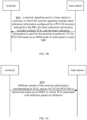
- FIG. 5 is a schematic flow chart of a method for processing information according to an exemplary embodiment.
- the method for processing information is applicable to the base station in the wireless communication system shown in FIG. 1 .
- the method may include the following steps.
- a network signaling is sent to the terminal, in which the network signaling includes: beam indication information configured for a PUCCH resource indicated by a PRI, the beam indication information includes multiple TCIs, and the beam indication information is used by the terminal to perform coherent joint transmission (C-JT) of PUCCHs based on an SDM mode of multi-panel or multi-TRP.
- the network signaling includes: beam indication information configured for a PUCCH resource indicated by a PRI, the beam indication information includes multiple TCIs, and the beam indication information is used by the terminal to perform coherent joint transmission (C-JT) of PUCCHs based on an SDM mode of multi-panel or multi-TRP.
- C-JT coherent joint transmission
- each data stream involved in the joint transmission for the PUCCHs will be mapped to multi-TRP through weighted vectors during a precoding process.
- the multiple TCIs include a first TCI and a second TCI.
- the first TCI is configured to indicate a transmission beam direction of a first panel of the terminal or a beam direction for PUCCH transmission toward the first TRP of the base station.
- the second TCI is configured to indicate a transmission beam direction of a second panel of the terminal or a beam direction for PUCCH transmission toward the second TRP of the base station.
- demodulation reference signal (DMRS) ports associated with different TCIs are the same.
- the terminal when the terminal transmits same uplink control information (UCI) through PUCCHs of different panels, the same time-frequency resource is used.
- UCI uplink control information
- different panels of the terminal performing the C-JT of PUCCHs use a same precoding matrix.
- all antenna units of all panels of the terminal send precoding information through a same precoder, and are beamforming in correspondence with the beam directions indicated by two different TCIs.
- different TCIs are applied to all PUCCH resources in a PUCCH resource group of the PUCCHs.
- the PUCCH resource is configured to not support repetition; or the PUCCH resource is configured to support slot-based repetition; or the PUCCH resource is configured to support sub-slot-based repetition.
- the PUCCH transmission includes at least one of:
- the PUCCH resource is configured to perform the PUCCH transmission based on the SDM at each hop of intra-slot frequency hopping; or, the PUCCH resource is configured to perform the PUCCH transmission based on the SDM at each hop of inter-slot frequency hopping.
- the TCI includes one of:
- indication information of the TCIs has a plurality of TCI fields; and one TCI field indicates a TCI corresponding to one panel of the terminal.
- indication information of the TCIs has one TCI field; and different codepoints of the TCI field indicate the TCIs of the multi-panel of the terminal.
- FIG. 6A is a schematic flow chart of a method for processing information according to an exemplary embodiment.
- the method for processing information is applicable to the terminal in the wireless communication system shown in FIG. 1 .
- the method may include the following steps.
- a network signaling sent by a base station is received, in which the network signaling includes: beam indication information configured for a PUCCH resource indicated by the PRI, the beam indication information includes multiple TCIs, and the beam indication information is used for the terminal to perform NC-JT for the PUCCHs based on the SDM mode of multi-panel or multi-TRP.
- the multiple TCIs include a first TCI and a second TCI.
- the first TCI is configured to indicate a transmission beam direction of a first panel of the terminal or a beam direction for PUCCH transmission toward a first TRP of the base station.
- the second TCI is configured to indicate a transmission beam direction of a second panel of the terminal or a beam direction for PUCCH transmission towards a second TRP of the base station.
- DMRS ports associated with different TCIs are the same.
- the same time-frequency resource is used.
- different panels of the terminal performing the NC-JT of PUCCHs use different precoding matrices.
- different TCIs are applied to all PUCCH resources in a PUCCH resource group of the PUCCHs.
- the PUCCH resource is configured to not support repetition; or the PUCCH resource is configured to support slot-based repetition; or the PUCCH resource is configured to support sub-slot-based repetition.
- the PUCCH transmission includes at least one of:
- the TCI includes one of:
- indication information of the TCIs has a plurality of TCI fields; and one TCI field indicates a TCI corresponding to one panel of the terminal.
- indication information of the TCIs has one TCI field; and different codepoints of the TCI field indicate the TCIs of the multi-panel of the terminal.
- FIG. 6B is a schematic flow chart of a method for processing information according to an exemplary embodiment.
- the method for processing information is applicable to the terminal in the wireless communication system shown in FIG. 1 .
- the method may include the following steps.
- a network signaling sent by a base station is received, in which the network signaling includes beam indication information configured for a PUCCH resource indicated by the PRI, the beam indication information includes multiple TCIs, and the beam indication information is used for the terminal to perform C-JT of PUCCHs based on an SDM mode of multi-panel or multi-TRP.
- each data stream involved in the joint transmission for the PUCCHs will be mapped to multi-TRP through weighted vectors during a precoding process.
- the multiple TCIs include a first TCI and a second TCI.
- the first TCI is configured to indicate a transmission beam direction of a first panel of the terminal or a beam direction for PUCCH transmission toward the first TRP of the base station.
- the second TCI is configured to indicate a transmission beam direction of a second panel of the terminal or a beam direction for PUCCH transmission toward the second TRP of the base station.
- DMRS ports associated with different TCIs are the same.
- the same time-frequency resource is used.
- different panels of the terminal performing the C-JT of PUCCHs use a same precoding matrix.
- all antenna units of all panels of the terminal send precoding information through a same precoder, and are beamforming in correspondence with the beam directions indicated by two different TCIs.
- different TCIs are applied to all PUCCH resources in a PUCCH resource group of the PUCCHs.
- the PUCCH resource is configured to not support repetition; or the PUCCH resource is configured to support slot-based repetition; or the PUCCH resource is configured to support sub-slot-based repetition.
- the PUCCH transmission includes at least one of:
- the PUCCH resource is configured to perform the PUCCH transmission based on the SDM at each hop of intra-slot frequency hopping; or the PUCCH resource is configured to perform the PUCCH transmission based on the SDM at each hop of inter-slot frequency hopping.
- the TCI includes one of:
- indication information of the TCIs has a plurality of TCI fields; and one TCI field indicates a TCI corresponding to one panel of the terminal.
- indication information of the TCIs has one TCI field; and different codepoints of the TCI field indicate the TCIs of the multi-panel of the terminal.
- FIG. 6C is a schematic flowchart of a method for uplink multi-panel PUCCH transmission according to an exemplary embodiment. The method is applicable to the terminal in the wireless communication system shown in FIG. 1 . As shown in FIG. 6C , this method includes the following steps.
- S50 Different panels of the terminal adopt beams corresponding to TCIs, and an NC-JT of PUCCHs is performed based on an SDM, in which TCIs associated with different panels are different.
- the method may further include: receiving, by the terminal, a network signaling sent by a base station, in which the network signaling includes: beam indication information configured for a PUCCH resource indicated by a PRI, the beam indication information includes multiple TCIs, and the beam indication information is used by the terminal to perform the NC-JT of PUCCHs based on an SDM mode of multi-panel/multi-TRP.
- the multiple TCIs include a first TCI and a second TCI.
- the first TCI is configured to indicate a transmission beam direction of a first panel of the terminal or a beam direction for PUCCH transmission toward a first TRP of the base station.
- the second TCI is configured to indicate a transmission beam direction of a second panel of the terminal or a beam direction for PUCCH transmission towards a second TRP of the base station.
- DMRS ports associated with different TCIs are the same.
- the same time-frequency resource is used.
- different panels of the terminal performing the NC-JT of PUCCHs use different precoding matrices.
- different TCIs are applied to all PUCCH resources in a PUCCH resource group of the PUCCHs.
- the PUCCH resource is configured to not support repetition; or the PUCCH resource is configured to support slot-based repetition; or the PUCCH resource is configured to support sub-slot-based repetition.
- the PUCCH transmission includes at least one of:
- the PUCCH resource is configured to perform the PUCCH transmission based on the SDM at each hop of intra-slot frequency hopping; or the PUCCH resource is configured to perform the PUCCH transmission based on the SDM at each hop of inter-slot frequency hopping.
- the TCI includes one of:
- indication information of the TCIs has a plurality of TCI fields; and one TCI field indicates a TCI corresponding to one panel of the terminal.
- indication information of the TCIs has one TCI field; and different codepoints of the TCI field indicate the TCIs of the multi-panel of the terminal.
- FIG. 6D is a schematic flowchart of a method for uplink multi-panel PUCCH transmission according to an exemplary embodiment. The method is applicable to the terminal in the wireless communication system shown in FIG. 1 . As shown in FIG. 6D , this method includes the following steps.
- S60 Different panels of the terminal adopt beams corresponding to TCIs and a C-JT of PUCCHs is performed based on an SDM, in which TCIs associated with different panels are different.
- the method may further include: receiving, by the terminal, a network signaling sent by a base station, in which the network signaling includes: beam indication information configured for a PUCCH resource indicated by a PRI, the beam indication information includes multiple TCIs, and the beam indication information is used by the terminal to perform the C-JT of PUCCHs based on an SDM mode of multi-panel/multi-TRP.
- the different TCIs include a first TCI and a second TCI.
- the first TCI is configured to indicate a transmission beam direction of a first panel of the terminal or a beam direction for PUCCH transmission toward the first TRP of the base station.
- the second TCI is configured to indicate a transmission beam direction of a second panel of the terminal or a beam direction for PUCCH transmission toward the second TRP of the base station.
- DMRS ports associated with different TCIs are the same.
- the same time-frequency resource is used.
- different panels of the terminal performing the C-JT of PUCCHs use a same precoding matrix.
- different TCIs are applied to all PUCCH resources in a PUCCH resource group of the PUCCHs.
- the PUCCH resource is configured to not support repetition; or the PUCCH resource is configured to support slot-based repetition; or the PUCCH resource is configured to support sub-slot-based repetition.
- the PUCCH transmission includes at least one of:
- the PUCCH resource is configured to perform the PUCCH transmission based on the SDM at each hop of intra-slot frequency hopping; or the PUCCH resource is configured to perform the PUCCH transmission based on the SDM at each hop of inter-slot frequency hopping.
- the TCI includes one of:
- indication information of the TCIs has a plurality of TCI fields; in which one TCI field indicates a TCI corresponding to one panel of the terminal.
- the embodiments of the present disclosure provide a method for processing information, the simultaneous PUCCH transmission is performed based on the SDM mode of the multi-panel/multi-TRP, to support higher throughput and more reliable transmission performance.
- the terminal is required to have the simultaneous multi-panel transmission capability.
- Each TCI contains a different QCL Type-D source RS, and the terminal uses the panel corresponding to the QCL Type-D source RS contained in the TCI for reception.
- TCI1 and TCI2 are associated with the same DMRS port at the same time, and the same UCI data is mapped on the same time-frequency resource through different panels/TRPs.
- a PUCCH resource group includes multiple PUCCH resources.
- a pair of activated or indicated TCIs may be applied to all PUCCH resources in the PUCCH resource group where the PUCCH is located at the same time.
- the PUCCH may also use a pair of TCIs that support multi-panel/multi-TRP transmission and are effective for the PUCCH resource group where the PUCCH is located.
- Different TCI applies different precoder for precoding, and the corresponding panel uses its own precoder to send PUCCH.
- PUCCH transmission formats such as PUCCH format 1 are supported.
- Different transmission methods of the PUCCH resource are supported, including: transmission without repetition, configuration of repetition based on slot/sub-slot in the same slot or multiple slots.
- the above-mentioned SDM mode may be used for transmission on each hop.
- the above-mentioned SDM mode may be used for transmission on each slot-level hop.
- TCI1 and TCI2 are associated with the same DMRS port at the same time, and the same UCI data is mapped on the same time-frequency resource through different panels/TRPs.
- the TCIs may be applied, at the same time, to all PUCCH resources in the PUCCH resource group where the PUCCH is located.
- All antenna units of all panels of the terminal send precoding information through a same precoder, and are beamforming in correspondence to two different TCI directions.
- PUCCH transmission formats such as PUCCH format 1 are supported.
- Different transmission schemes for PUCCH resources are supported, including: transmission without repetition, repetition based on slot/sub-slot configured in a same slot or multiple slots.
- the above-mentioned SDM mode may be used for transmission on each hop.
- the above-mentioned SDM mode may be used for transmission on each slot-level hop.
- the SDM transmission scheme and beam indication method for the uplink PUCCH channel supporting multi-panel/multi-TRP transmission under S-DCI scheduling are provided.
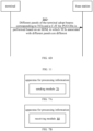
- FIG. 7A is a block diagram of an apparatus for processing information, applied to a base station, according to an exemplary embodiment of the present disclosure.
- the apparatus for processing information can be implemented as all or part of the base station in the implementation environment shown in FIG. 1 , through hardware or a combination of software and hardware, to perform steps of the methods for processing information in the embodiments shown in FIG. 2 or FIG. 5 .
- the apparatus for processing information may include:
- a sending module 70 configured to send a network signaling to a terminal, in which the network signaling includes beam indication information configured for a PUCCH resource indicated by a PRI, the beam indication information includes multiple TCIs, and the beam indication information is used by the terminal to perform joint transmission for PUCCHs based on an SDM mode of multi-panel or multi-TRP.
- the multiple TCIs include a first TCI and a second TCI.
- the first TCI is configured to indicate a transmission beam direction of a first panel of the terminal or a beam direction for PUCCH transmission towards a first TRP of the base station.
- the second TCI is configured to indicate a transmission beam direction of a second panel of the terminal or a beam direction for PUCCH transmission towards a second TRP of the base station.
- DMRS ports associated with different TCIs are the same.
- a same time-frequency resource is used.
- the PUCCH transmission is: NC-JT for the PUCCHs, or C-JT for the PUCCHs.
- different panels of the terminal performing the NC-JT of PUCCHs use different precoding matrices.
- different panels of the terminal performing the C-JT of PUCCHs use a same precoding matrix.
- different TCIs are applied to all PUCCH resources in a PUCCH resource group of the PUCCHs.
- the PUCCH resource is configured to not support repetition; or the PUCCH resource is configured to support slot-based repetition; or the PUCCH resource is configured to support sub-slot-based repetition.
- the PUCCH transmission includes at least one of:
- the PUCCH resource is configured to perform the PUCCH transmission based on the SDM at each hop of intra-slot frequency hopping; or the PUCCH resource is configured to perform the PUCCH transmission based on the SDM at each hop of inter-slot frequency hopping.
- the TCI includes one of:
- indication information of the TCIs has a plurality of TCI fields; in which one TCI field indicates a TCI corresponding to one panel of the terminal.
- indication information of the TCIs has one TCI field; different codepoints of the TCI field indicate the TCIs of multi-panel of the terminal.
- the network signaling includes at least one of:
- FIG. 7B is a block diagram of an apparatus for processing information, applied to a terminal, according to an exemplary embodiment of the present disclosure.
- the apparatus for processing information can be implemented as all or part of the terminal in the implementation environment shown in FIG. 1 , through hardware or a combination of software and hardware, to perform steps of the methods for information processing in the embodiment shown in FIG. 6A or FIG. 6B .
- the apparatus for processing information may include: a receiving module 80, configured to receive a network signaling sent by the base station, in which the network signaling includes beam indication information configured for a PUCCH resource indicated by the PRI, the beam indication information includes multiple TCIs, and the beam indication information is used by the terminal to perform joint transmission for PUCCHs based on an SDM mode of multi-panel or multi-TRP.
- a receiving module 80 configured to receive a network signaling sent by the base station, in which the network signaling includes beam indication information configured for a PUCCH resource indicated by the PRI, the beam indication information includes multiple TCIs, and the beam indication information is used by the terminal to perform joint transmission for PUCCHs based on an SDM mode of multi-panel or multi-TRP.
- the multiple TCIs include a first TCI and a second TCI.
- the first TCI is configured to indicate a transmission beam direction of a first panel of the terminal or a beam direction for PUCCH transmission towards a first TRP of the base station.
- the second TCI is configured to indicate a transmission beam direction of a second panel of the terminal or a beam direction for PUCCH transmission towards a second TRP of the base station.
- DMRS ports associated with different TCIs are the same.
- a same time-frequency resource is used.
- the PUCCH transmission includes: NC-JT for the PUCCHs, or C-JT for the PUCCHs.
- different panels of the terminal performing the NC-JT of PUCCHs use different precoding matrices.
- different panels of the terminal perform the C-JT of PUCCHs use a same precoding matrix.
- different TCIs are applied to all PUCCH resources in a PUCCH resource group of the PUCCHs.
- the PUCCH resource is configured to not support repetition; or the PUCCH resource is configured to support slot-based repetition; or the PUCCH resource is configured to support sub-slot-based repetition.
- the PUCCH transmission includes at least one of:
- the PUCCH resource is configured to perform the PUCCH transmission based on the SDM at each hop of intra-slot frequency hopping; or the PUCCH resource is configured to perform the PUCCH transmission based on the SDM at each hop of inter-slot frequency hopping.
- the TCI includes one of:
- indication information of the TCIs has a plurality of TCI fields; in which one TCI field indicates a TCI corresponding to one panel of the terminal.
- indication information of the TCIs has one TCI field; different codepoints of the TCI field indicate the TCIs of multi-panel of the terminal.
- the network signaling includes at least one of:
- An embodiment of the present disclosure provides a terminal, including a processor, a memory, and an executable program stored in the memory and capable of being run by the processor.
- the processor runs the executable program, it executes the steps of the methods for processing information applied to terminals or the method for uplink multi-panel PUCCH transmission in the foregoing embodiments.
- the processor may include various types of storage media, which are non-transitory computer storage media that can continue to store information stored thereon after the terminal is powered off.
- the processor may be connected to the memory through a bus or the like, and be used to read the executable program stored on the memory, for example, at least one of the methods shown in FIGS. 6A to 6D .
- FIG. 8 is a block diagram of a terminal according to an exemplary embodiment.
- the terminal 800 may be a mobile phone, a computer, a digital broadcast user device, a messaging device, a game console, a tablet device, a medical device, a fitness device, a personal digital assistant, or the like.
- the terminal 800 may include one or more of the following components: a processing component 802, a memory 804, a power supply component 806, a multimedia component 808, an audio component 810, an input/output (I/O) interface 812, a sensor component 814, and a communication component 816.
- the processing component 802 generally controls the overall operations of the terminal 800, such as operations associated with display, phone calls, data communications, camera operations, and recording operations.
- the processing component 802 may include one or more processors 820 to execute instructions to generate all or part of the steps of the methods described above. Additionally, the processing component 802 may include one or more modules that facilitate interaction between the processing component 802 and other components. For example, the processing component 802 may include a multimedia module to facilitate interaction between the multimedia component 808 and the processing component 802.
- the audio component 810 is configured to output and/or input audio signals.
- the audio component 810 includes a microphone (MIC) configured to receive external audio signals when the terminal 800 is in operating modes, such as call mode, recording mode, and voice recognition mode.
- the received audio signal may be further stored in the memory 804 or sent via the communication component 816.
- the audio component 810 also includes a speaker for outputting audio signals.
- the I/O interface 812 provides an interface between the processing component 802 and a peripheral interface module, which may be a keyboard, a click wheel, a button, etc. These buttons may include, but are not limited to: a home button, a volume button, a start button, and a lock button.
- the sensor component 814 includes one or more sensors that provide various aspects of status assessment for the terminal 800.
- the sensor component 814 can detect the open/closed state of the device 800, the relative positioning of components, such as the display and keypad of the terminal 800, and the sensor component 814 can also detect the position change of the terminal 800 or a component of the terminal 800, the presence or absence of user contact with the terminal 800, the orientation or acceleration/deceleration of the terminal 800 and the temperature change of the terminal 800.
- the sensor component 814 may include a proximity sensor configured to detect the presence of nearby objects without any physical contact.
- the sensor component 814 may also include a light sensor, such as a CMOS or CCD image sensor, for use in imaging applications.
- the sensor component 814 may also include an acceleration sensor, a gyroscope sensor, a magnetic sensor, a pressure sensor, or a temperature sensor.
- the communication component 816 is configured to facilitate wired or wireless communication between the terminal 800 and other devices.
- the terminal 800 can access a wireless network based on a communication standard, such as WiFi, 2G, 3G, 4G or 5G, or a combination thereof.
- the communication component 816 receives broadcast signals or broadcast related information from an external broadcast management system via a broadcast channel.
- the communications component 816 also includes a near field communications (NFC) module to facilitate short-range communications.
- NFC near field communications
- the NFC module can be implemented based on radio frequency identification (RFID) technology, infrared data association (IrDA) technology, ultra-wideband (UWB) technology, Bluetooth (BT) technology and other technologies.
- RFID radio frequency identification
- IrDA infrared data association
- UWB ultra-wideband
- Bluetooth Bluetooth
- the terminal 800 may be configured to by one or more application specific integrated circuits (ASICs), digital signal processors (DSPs), digital signal processing devices (DSPDs), programmable logic devices (PLDs), field programmable gate arrays (FPGAs), controllers, microcontrollers, microprocessors or other electronic components are implemented for executing the above method.
- ASICs application specific integrated circuits
- DSPs digital signal processors
- DSPDs digital signal processing devices
- PLDs programmable logic devices
- FPGAs field programmable gate arrays
- controllers microcontrollers, microprocessors or other electronic components are implemented for executing the above method.
- a non-transitory computer-readable storage medium including instructions, such as a memory 804 including instructions.
- the instructions may be executed by the processor 820 of the terminal 800 to perform any of the above methods applied to the terminal.
- the non-transitory computer-readable storage medium may be a ROM, random access memory (RAM), CD-ROM, magnetic tape, floppy disk, optical data storage device, etc.
- FIG. 9 is a block diagram of a base station according to an exemplary embodiment.
- the base station 900 may be provided as a network device.
- the base station 900 includes a processing component 922, which further includes one or more processors, and memory resources represented by the memory 932 for storing instructions, such as application programs, executable by the processing component 922.
- the application program stored in the memory 932 may include one or more modules, each corresponding to a set of instructions.
- the processing component 922 is configured to execute instructions to perform any of the foregoing methods applied to the base station, for example, the method shown in FIG. 2 or FIG. 5 .
- the base station 900 may also include a power supply component 926 configured to perform power management of the base station 900, a wired or wireless network interface 950 configured to connect the base station 900 to a network, and an input/output (I/O) interface 958.
- the base station 900 may operate based on an operating system stored in the memory 932, such as Windows Server TM , Mac OS X TM , Unix TM , Linux TM , FreeBSD TM or the like.
- a non-transitory computer-readable storage medium including instructions, such as a memory 932 including instructions.
- the instructions can be used by the processing component 922 of the base station 900 to perform any of the above methods applied in the base station.
- the non-transitory computer-readable storage medium may be a ROM, a random access memory (RAM), a CD-ROM, a magnetic tape, a floppy disk, an optical data storage device, etc.
Landscapes
- Engineering & Computer Science (AREA)
- Signal Processing (AREA)
- Computer Networks & Wireless Communication (AREA)
- Physics & Mathematics (AREA)
- Mathematical Physics (AREA)
- Mobile Radio Communication Systems (AREA)
Applications Claiming Priority (1)
| Application Number | Priority Date | Filing Date | Title |
|---|---|---|---|
| PCT/CN2022/090764 WO2023206559A1 (zh) | 2022-04-29 | 2022-04-29 | 信息处理方法、装置、终端、基站及存储介质 |
Publications (2)
| Publication Number | Publication Date |
|---|---|
| EP4518481A1 true EP4518481A1 (de) | 2025-03-05 |
| EP4518481A4 EP4518481A4 (de) | 2025-05-21 |
Family
ID=88517064
Family Applications (1)
| Application Number | Title | Priority Date | Filing Date |
|---|---|---|---|
| EP22939403.6A Pending EP4518481A4 (de) | 2022-04-29 | 2022-04-29 | Informationsverarbeitungsverfahren und -vorrichtung sowie endgerät, basisstation und speichermedium |
Country Status (4)
| Country | Link |
|---|---|
| US (1) | US20250301472A1 (de) |
| EP (1) | EP4518481A4 (de) |
| CN (1) | CN117322098A (de) |
| WO (1) | WO2023206559A1 (de) |
Families Citing this family (2)
| Publication number | Priority date | Publication date | Assignee | Title |
|---|---|---|---|---|
| WO2025166666A1 (zh) * | 2024-02-07 | 2025-08-14 | 北京小米移动软件有限公司 | 波束指示方法、终端、网络设备、通信系统及存储介质 |
| WO2025189360A1 (zh) * | 2024-03-12 | 2025-09-18 | 北京小米移动软件有限公司 | 信息处理方法、通信设备及存储介质 |
Family Cites Families (10)
| Publication number | Priority date | Publication date | Assignee | Title |
|---|---|---|---|---|
| WO2021010709A1 (ko) * | 2019-07-12 | 2021-01-21 | 엘지전자 주식회사 | 무선 통신 시스템에서 상향링크 채널을 송수신 하는 방법 및 이에 대한 장치 |
| US11832283B2 (en) * | 2019-07-25 | 2023-11-28 | Qualcomm Incorporated | Details of physical uplink control channel (PUCCH) repetition with different beams |
| WO2021185089A1 (en) * | 2020-03-19 | 2021-09-23 | Qualcomm Incorporated | Configuration and indication for enabling uplink transmission with multiple codewords |
| KR20230002366A (ko) * | 2020-04-17 | 2023-01-05 | 엘지전자 주식회사 | 무선 통신 시스템에서 상향링크 송수신 방법 및 장치 |
| WO2022006833A1 (en) * | 2020-07-10 | 2022-01-13 | Qualcomm Incorporated | Uplink control information multiplexing for multiple panels |
| WO2022020694A1 (en) * | 2020-07-24 | 2022-01-27 | Comcast Cable Communications, Llc | Transmission repetition for wireless communication |
| KR102919483B1 (ko) * | 2020-09-30 | 2026-01-28 | 퀄컴 인코포레이티드 | 멀티-패널 업링크 송신들을 위한 디폴트 경로손실 참조 신호들 |
| US20230421233A1 (en) * | 2020-10-16 | 2023-12-28 | JRD Communication (Shenzhen) Ltd. | Transmission method, multi-trp/panel system and ue |
| WO2022147755A1 (en) * | 2021-01-08 | 2022-07-14 | Zte Corporation | Unified transmission configuration indicators in multiple transmission reception point environments |
| EP4496405A4 (de) * | 2022-03-18 | 2026-01-07 | Ntt Docomo Inc | Endgerät, funkkommunikationsverfahren und basisstation |
-
2022
- 2022-04-29 US US18/860,148 patent/US20250301472A1/en active Pending
- 2022-04-29 EP EP22939403.6A patent/EP4518481A4/de active Pending
- 2022-04-29 WO PCT/CN2022/090764 patent/WO2023206559A1/zh not_active Ceased
- 2022-04-29 CN CN202280001506.7A patent/CN117322098A/zh active Pending
Also Published As
| Publication number | Publication date |
|---|---|
| CN117322098A (zh) | 2023-12-29 |
| EP4518481A4 (de) | 2025-05-21 |
| WO2023206559A1 (zh) | 2023-11-02 |
| US20250301472A1 (en) | 2025-09-25 |
Similar Documents
| Publication | Publication Date | Title |
|---|---|---|
| CN111512685B (zh) | 信道状态信息测量方法、装置及计算机存储介质 | |
| CN110537334A (zh) | 天线面板的应用方法、装置及存储介质 | |
| CN111543076B (zh) | 传输方法、装置及计算机存储介质 | |
| US12446085B2 (en) | Method for wireless communication, and communication device | |
| EP4668636A1 (de) | Referenzsignalübertragungsverfahren und -vorrichtung, kommunikationsvorrichtung und speichermedium | |
| EP4518481A1 (de) | Informationsverarbeitungsverfahren und -vorrichtung sowie endgerät, basisstation und speichermedium | |
| US20250261198A1 (en) | Uplink transmission configuration method, communication device and storage medium | |
| US20260031884A1 (en) | Beam reporting enhancement method and apparatus, and communication device and storage medium | |
| US20250294558A1 (en) | Physical uplink control channel (pucch) transmission method and communication device | |
| EP4518476A1 (de) | Verfahren und vorrichtung zur konfiguration eines gemeinsam genutzten physikalischen uplink-kanals, kommunikationsvorrichtung und speichermedium | |
| EP4518215B1 (de) | Verfahren und vorrichtung zur konfiguration eines gemeinsam genutzten physikalischen uplink-kanals, kommunikationsvorrichtung und speichermedium | |
| US20250294564A1 (en) | Physical uplink control channel transmission method and apparatus, communication device, and storage medium | |
| EP4679916A1 (de) | Kommunikationsverfahren und -vorrichtung sowie speichermedium | |
| EP4668967A1 (de) | Verfahren und vorrichtung zur übertragung eines gemeinsam genutzten physikalischen uplink-kanals und speichermedium | |
| EP4668638A1 (de) | Verfahren und vorrichtung zur kommunikation über einen gemeinsam genutzten physikalischen uplink-kanal (pusch) und speichermedium | |
| WO2023206290A1 (zh) | Pusch传输配置方法及装置、通信设备及存储介质 | |
| WO2023206288A1 (zh) | 传输方式指示方法、装置、通信设备及存储介质 | |
| US20240195571A1 (en) | Method and device for enhancing uplink phase tracking reference signal (pt-rs) | |
| WO2026031764A1 (zh) | 一种通信方法及通信装置 | |
| WO2024026682A1 (zh) | 波束上报方法及装置、通信设备及存储介质 | |
| WO2023206227A1 (zh) | 冗余版本rv的指示方法、装置、通信设备及存储介质 |
Legal Events
| Date | Code | Title | Description |
|---|---|---|---|
| STAA | Information on the status of an ep patent application or granted ep patent |
Free format text: STATUS: THE INTERNATIONAL PUBLICATION HAS BEEN MADE |
|
| PUAI | Public reference made under article 153(3) epc to a published international application that has entered the european phase |
Free format text: ORIGINAL CODE: 0009012 |
|
| STAA | Information on the status of an ep patent application or granted ep patent |
Free format text: STATUS: REQUEST FOR EXAMINATION WAS MADE |
|
| 17P | Request for examination filed |
Effective date: 20241127 |
|
| AK | Designated contracting states |
Kind code of ref document: A1 Designated state(s): AL AT BE BG CH CY CZ DE DK EE ES FI FR GB GR HR HU IE IS IT LI LT LU LV MC MK MT NL NO PL PT RO RS SE SI SK SM TR |
|
| A4 | Supplementary search report drawn up and despatched |
Effective date: 20250417 |
|
| RIC1 | Information provided on ipc code assigned before grant |
Ipc: H04L 5/00 20060101ALI20250411BHEP Ipc: H04L 1/08 20060101ALI20250411BHEP Ipc: H04B 7/02 20180101ALI20250411BHEP Ipc: H04W 72/04 20230101AFI20250411BHEP |
|
| DAV | Request for validation of the european patent (deleted) | ||
| DAX | Request for extension of the european patent (deleted) |