EP4517993A1 - Natriumionenbatterie, batterie und elektrische vorrichtung - Google Patents
Natriumionenbatterie, batterie und elektrische vorrichtung Download PDFInfo
- Publication number
- EP4517993A1 EP4517993A1 EP23909190.3A EP23909190A EP4517993A1 EP 4517993 A1 EP4517993 A1 EP 4517993A1 EP 23909190 A EP23909190 A EP 23909190A EP 4517993 A1 EP4517993 A1 EP 4517993A1
- Authority
- EP
- European Patent Office
- Prior art keywords
- sodium
- electrode plate
- negative electrode
- positive electrode
- ion battery
- Prior art date
- Legal status (The legal status is an assumption and is not a legal conclusion. Google has not performed a legal analysis and makes no representation as to the accuracy of the status listed.)
- Pending
Links
Images


Classifications
-
- H—ELECTRICITY
- H01—ELECTRIC ELEMENTS
- H01M—PROCESSES OR MEANS, e.g. BATTERIES, FOR THE DIRECT CONVERSION OF CHEMICAL ENERGY INTO ELECTRICAL ENERGY
- H01M50/00—Constructional details or processes of manufacture of the non-active parts of electrochemical cells other than fuel cells, e.g. hybrid cells
- H01M50/40—Separators; Membranes; Diaphragms; Spacing elements inside cells
- H01M50/489—Separators, membranes, diaphragms or spacing elements inside the cells, characterised by their physical properties, e.g. swelling degree, hydrophilicity or shut down properties
- H01M50/497—Ionic conductivity
-
- H—ELECTRICITY
- H01—ELECTRIC ELEMENTS
- H01M—PROCESSES OR MEANS, e.g. BATTERIES, FOR THE DIRECT CONVERSION OF CHEMICAL ENERGY INTO ELECTRICAL ENERGY
- H01M10/00—Secondary cells; Manufacture thereof
- H01M10/05—Accumulators with non-aqueous electrolyte
- H01M10/054—Accumulators with insertion or intercalation of metals other than lithium, e.g. with magnesium or aluminium
-
- H—ELECTRICITY
- H01—ELECTRIC ELEMENTS
- H01M—PROCESSES OR MEANS, e.g. BATTERIES, FOR THE DIRECT CONVERSION OF CHEMICAL ENERGY INTO ELECTRICAL ENERGY
- H01M10/00—Secondary cells; Manufacture thereof
- H01M10/05—Accumulators with non-aqueous electrolyte
- H01M10/056—Accumulators with non-aqueous electrolyte characterised by the materials used as electrolytes, e.g. mixed inorganic/organic electrolytes
- H01M10/0564—Accumulators with non-aqueous electrolyte characterised by the materials used as electrolytes, e.g. mixed inorganic/organic electrolytes the electrolyte being constituted of organic materials only
- H01M10/0565—Polymeric materials, e.g. gel-type or solid-type
-
- H—ELECTRICITY
- H01—ELECTRIC ELEMENTS
- H01M—PROCESSES OR MEANS, e.g. BATTERIES, FOR THE DIRECT CONVERSION OF CHEMICAL ENERGY INTO ELECTRICAL ENERGY
- H01M50/00—Constructional details or processes of manufacture of the non-active parts of electrochemical cells other than fuel cells, e.g. hybrid cells
- H01M50/40—Separators; Membranes; Diaphragms; Spacing elements inside cells
- H01M50/409—Separators, membranes or diaphragms characterised by the material
- H01M50/411—Organic material
- H01M50/414—Synthetic resins, e.g. thermoplastics or thermosetting resins
-
- H—ELECTRICITY
- H01—ELECTRIC ELEMENTS
- H01M—PROCESSES OR MEANS, e.g. BATTERIES, FOR THE DIRECT CONVERSION OF CHEMICAL ENERGY INTO ELECTRICAL ENERGY
- H01M50/00—Constructional details or processes of manufacture of the non-active parts of electrochemical cells other than fuel cells, e.g. hybrid cells
- H01M50/40—Separators; Membranes; Diaphragms; Spacing elements inside cells
- H01M50/409—Separators, membranes or diaphragms characterised by the material
- H01M50/44—Fibrous material
-
- H—ELECTRICITY
- H01—ELECTRIC ELEMENTS
- H01M—PROCESSES OR MEANS, e.g. BATTERIES, FOR THE DIRECT CONVERSION OF CHEMICAL ENERGY INTO ELECTRICAL ENERGY
- H01M50/00—Constructional details or processes of manufacture of the non-active parts of electrochemical cells other than fuel cells, e.g. hybrid cells
- H01M50/40—Separators; Membranes; Diaphragms; Spacing elements inside cells
- H01M50/409—Separators, membranes or diaphragms characterised by the material
- H01M50/449—Separators, membranes or diaphragms characterised by the material having a layered structure
-
- H—ELECTRICITY
- H01—ELECTRIC ELEMENTS
- H01M—PROCESSES OR MEANS, e.g. BATTERIES, FOR THE DIRECT CONVERSION OF CHEMICAL ENERGY INTO ELECTRICAL ENERGY
- H01M50/00—Constructional details or processes of manufacture of the non-active parts of electrochemical cells other than fuel cells, e.g. hybrid cells
- H01M50/40—Separators; Membranes; Diaphragms; Spacing elements inside cells
- H01M50/489—Separators, membranes, diaphragms or spacing elements inside the cells, characterised by their physical properties, e.g. swelling degree, hydrophilicity or shut down properties
- H01M50/494—Tensile strength
-
- H—ELECTRICITY
- H01—ELECTRIC ELEMENTS
- H01M—PROCESSES OR MEANS, e.g. BATTERIES, FOR THE DIRECT CONVERSION OF CHEMICAL ENERGY INTO ELECTRICAL ENERGY
- H01M50/00—Constructional details or processes of manufacture of the non-active parts of electrochemical cells other than fuel cells, e.g. hybrid cells
- H01M50/50—Current conducting connections for cells or batteries
- H01M50/572—Means for preventing undesired use or discharge
- H01M50/584—Means for preventing undesired use or discharge for preventing incorrect connections inside or outside the batteries
- H01M50/586—Means for preventing undesired use or discharge for preventing incorrect connections inside or outside the batteries inside the batteries, e.g. incorrect connections of electrodes
-
- H—ELECTRICITY
- H01—ELECTRIC ELEMENTS
- H01M—PROCESSES OR MEANS, e.g. BATTERIES, FOR THE DIRECT CONVERSION OF CHEMICAL ENERGY INTO ELECTRICAL ENERGY
- H01M2300/00—Electrolytes
- H01M2300/0088—Composites
- H01M2300/0094—Composites in the form of layered products, e.g. coatings
-
- H—ELECTRICITY
- H01—ELECTRIC ELEMENTS
- H01M—PROCESSES OR MEANS, e.g. BATTERIES, FOR THE DIRECT CONVERSION OF CHEMICAL ENERGY INTO ELECTRICAL ENERGY
- H01M50/00—Constructional details or processes of manufacture of the non-active parts of electrochemical cells other than fuel cells, e.g. hybrid cells
- H01M50/50—Current conducting connections for cells or batteries
- H01M50/572—Means for preventing undesired use or discharge
- H01M50/584—Means for preventing undesired use or discharge for preventing incorrect connections inside or outside the batteries
- H01M50/59—Means for preventing undesired use or discharge for preventing incorrect connections inside or outside the batteries characterised by the protection means
- H01M50/593—Spacers; Insulating plates
-
- Y—GENERAL TAGGING OF NEW TECHNOLOGICAL DEVELOPMENTS; GENERAL TAGGING OF CROSS-SECTIONAL TECHNOLOGIES SPANNING OVER SEVERAL SECTIONS OF THE IPC; TECHNICAL SUBJECTS COVERED BY FORMER USPC CROSS-REFERENCE ART COLLECTIONS [XRACs] AND DIGESTS
- Y02—TECHNOLOGIES OR APPLICATIONS FOR MITIGATION OR ADAPTATION AGAINST CLIMATE CHANGE
- Y02E—REDUCTION OF GREENHOUSE GAS [GHG] EMISSIONS, RELATED TO ENERGY GENERATION, TRANSMISSION OR DISTRIBUTION
- Y02E60/00—Enabling technologies; Technologies with a potential or indirect contribution to GHG emissions mitigation
- Y02E60/10—Energy storage using batteries
Definitions
- This application relates to the field of battery technologies, and more specifically, to a sodium-ion battery, a battery, and an electric apparatus.
- sodium-ion batteries Due to advantages such as reliable operating performance, no pollution, and no memory effect, sodium-ion batteries have been widely used. For example, as environmental protection issues gain increasing attention and new energy vehicles become more prevalent, the demands for power-type sodium-ion batteries are in explosive growth.
- This application provides a sodium-ion battery, a battery, and an electric apparatus. This application can improve safety performance of the sodium-ion battery.
- this application provides a sodium-ion battery.
- the sodium-ion battery includes a positive electrode plate, a negative electrode plate, and an ion conductor.
- the ion conductor is located between the positive electrode plate and the negative electrode plate.
- the ion conductor is at least in contact with a surface of the negative electrode plate, the ion conductor is configured to conduct sodium ions between the positive electrode plate and the negative electrode plate, and sodium ions conducted to the surface of the negative electrode plate are reduced to sodium metal, where an elastic modulus of the ion conductor is E in GPa, where 0.10 ⁇ E ⁇ 5.00.
- the ion conductor of this application can isolate the positive electrode plate from the negative electrode plate, and can conduct sodium ions. Moreover, the ion conductor provides conduction paths for sodium ions, sodium ions migrate to the surface of the negative electrode plate through the ion conductor and gain electrons to become metal, and the range of sodium ions precipitated corresponds to the range of the ion conductor, such that the sodium metal is less likely to be precipitated to an end portion of the negative electrode plate in a height direction, such as the negative electrode plate, thereby reducing the risk of short circuit caused by contact between the negative electrode plate and the positive electrode plate.
- the ion conductor has excellent elasticity, which allows it to deform correspondingly in regions with increased precipitated sodium metal, reduces the risk of the sodium metal being squeezed out, and reduces the risk of short circuit caused by contact between the squeezed-out sodium metal and the positive electrode plate, thereby improving safety performance of the sodium-ion battery.
- the ion conductor includes a solid electrolyte.
- the solid electrolyte can provide migration paths for sodium ions, and when the solid electrolyte satisfies the foregoing elastic modulus range, its elasticity is more excellent, which facilitates deformation, reduces the risk of the sodium metal being squeezed out, and reduces the risk of short circuit caused by contact between the squeezed-out sodium metal and the positive electrode plate, thereby improving the safety performance of the sodium-ion battery.
- the ion conductor includes a continuously disposed matrix, and material of the matrix includes one or more of polyether compound, polyacrylonitrile, polyacrylate compound, and fluoropolymer.
- the polyether compound includes one or more of polyethylene oxide and polypropylene oxide.
- the polyacrylate compound includes one or more of polymethacrylate, polyethyl acrylate, and polyhydroxymethacrylate.
- the fluoropolymer includes polyvinylidene fluoride.
- the ion conductor includes a gel electrolyte.
- the gel electrolyte can provide migration paths for sodium ions, and when the solid electrolyte satisfies the foregoing elastic modulus range, its elasticity is more excellent, which facilitates deformation, reduces the risk of the sodium metal being squeezed out, and reduces the risk of short circuit caused by contact between the squeezed-out sodium metal and the positive electrode plate, thereby improving the safety performance of the sodium-ion battery.
- the ion conductor includes a continuously disposed matrix and a plasticizer located in the matrix.
- material of the matrix includes one or more of polyether compound, polyacrylonitrile, polyacrylate compound, and fluoropolymer.
- the polyether compound includes one or more of polyethylene oxide and polypropylene oxide.
- the polyacrylate compound includes one or more of polymethacrylate, polyethyl acrylate, and polyhydroxymethacrylate.
- the fluoropolymer includes one or more of polyvinylidene fluoride and vinylidene fluoride-hexafluoropropylene copolymer.
- the plasticizer includes one or more of dimethylformamide, diethyl carbonate, ⁇ -butyrolactone, ethylene carbonate, propylene carbonate, and polyethylene glycol.
- the ion conductor includes a supporting layer and a conducting layer, the conducting layer is located on a surface of the supporting layer, and the conducting layer is disposed on the surface of the negative electrode plate; where an elastic modulus of the conducting layer is E 1 in GPa, and an elastic modulus of the supporting layer is E 2 in GPa; where E 1 /E 2 ⁇ 1.
- the supporting layer has good mechanical performance, providing good support, and plays the role of insulation to isolate the positive electrode plate from the negative electrode plate and alleviate swelling.
- the conducting layer can conduct sodium ions, acting similarly to an electrolyte.
- the conducting layer includes a polymer matrix; and further optionally, the polymer matrix includes one or more of polyether compound, polyacrylonitrile, polyacrylate compound, and fluoropolymer.
- material of the supporting layer includes one or more of polyolefin-based resin film, glass fiber, and non-woven fabric.
- the sodium-ion battery further includes an insulating structure, the insulating structure is disposed on at least one side of the ion conductor in a height direction of the sodium-ion battery, and the insulating structure extends along a direction perpendicular to the height direction and extends to the surface of the negative electrode plate.
- the insulating structure of this application can further alleviate the risk of short circuit caused by sodium metal overflowing to the end portion of the negative electrode plate and coming into contact with the positive electrode plate, thereby further improving the safety performance of the sodium-ion battery.
- the insulating structure is disposed on two sides of the ion conductor in the height direction.
- the problem of metal overflowing can be alleviated on both sides of the ion conductor in the height direction, thereby further improving the safety performance of the sodium-ion battery.
- the insulating structure covers at least a portion of the positive electrode plate in the height direction. Therefore, the insulating structure can further isolate the positive electrode plate from the negative electrode plate, reducing the risk of contact between the positive electrode plate and the negative electrode plate, thereby further improving the safety performance of the sodium-ion battery.
- the positive electrode plate includes a positive electrode current collector and a positive electrode active substance layer disposed on at least one surface of the positive electrode current collector, the positive electrode active substance layer includes a positive electrode active substance, and the insulating structure covers the positive electrode active substance layer in the height direction.
- the insulating structure is configured to conduct the sodium ions between the positive electrode plate and the negative electrode plate, and the sodium ions conducted to the surface of the negative electrode plate are reduced to sodium metal.
- the insulating structure can further extend the migration paths of sodium ions, thereby further improving kinetic performance of the sodium-ion battery.
- the negative electrode plate includes a negative electrode current collector, and a surface of the negative electrode current collector is in contact with the ion conductor.
- the negative electrode plate includes a negative electrode current collector and a conductive layer disposed on at least one surface of the negative electrode current collector, a surface of the conductive layer is in contact with the ion conductor, and the conductive layer is configured to receive sodium ions such that the sodium ions are reduced to sodium metal.
- the conductive layer can enhance conductivity of the negative electrode plate, facilitating the deposition of sodium ions as sodium metal on the conductive layer.
- this application provides a battery.
- the battery includes the sodium-ion battery according to any one of the embodiments of the first aspect of this application.
- this application provides an electric apparatus.
- the electric apparatus includes the battery according to any one of the embodiments of the second aspect of this application.
- Ranges disclosed in this application are defined in the form of lower and upper limits.
- a given range is defined by one lower limit and one upper limit selected, where the selected lower and upper limits define boundaries of that particular range. Ranges defined in this method may or may not include end values, and any combinations may be used, meaning any lower limit may be combined with any upper limit to form a range. For example, if ranges of 60-120 and 80-110 are provided for a specific parameter, it is understood that ranges of 60-110 and 80-120 can also be envisioned. In addition, if minimum values of a range are given as 1 and 2, and maximum values of the range are given as 3, 4, and 5, the following ranges can all be envisioned: 1-3, 1-4, 1-5, 2-3, 2-4, and 2-5.
- a value range of "a-b” is a short representation of any combination of real numbers between a and b, where both a and b are real numbers.
- a value range of "0-5" means that all real numbers in the range of "0-5" are listed herein, and "0-5" is just a short representation of a combination of these values.
- a parameter expressed as an integer greater than or equal to 2 is equivalent to disclosure that the parameter is, for example, an integer among 2, 3, 4, 5, 6, 7, 8, 9, 10, 11, 12, and so on.
- a method including steps (a) and (b) indicates that the method may include steps (a) and (b) performed in order or may include steps (b) and (a) performed in order.
- the foregoing method may further include step (c), which indicates that step (c) may be added to the method in any ordinal position, for example, the method may include steps (a), (b), and (c), steps (a), (c), and (b), steps (c), (a), and (b), or the like.
- Alkali-ion batteries are widely used in the field of new energy due to advantages such as high energy density and high specific capacity.
- Alkali metal batteries typically include lithium-ion batteries and sodium-ion batteries.
- lithium-ion batteries typically include lithium-ion batteries and sodium-ion batteries.
- lithium resources in the crust are limited and unevenly distributed, the development of lithium-ion batteries is constrained; whereas sodium resources are abundant and widely distributed, showing their resource advantages.
- a sodium-ion battery includes an electrode assembly and an electrolyte.
- the electrode assembly includes a positive electrode plate, a negative electrode plate, and a separator.
- the separator is located between the positive electrode plate and the negative electrode plate to isolate the positive electrode plate from the negative electrode plate.
- Sodium ions migrate between the positive electrode plate and the negative electrode plate through the electrolyte to implement charging and discharging of the sodium-ion battery.
- the positive electrode plate may include a positive electrode current collector and a positive electrode active substance layer, and the positive electrode active substance layer is generally applied on a surface of the positive electrode current collector; while the negative electrode plate may not include a negative electrode active substance during preparation, for example, the negative electrode plate includes a negative electrode current collector.
- the inventors have found that during charging of the sodium-ion battery, sodium ions migrate from the positive electrode plate to the negative electrode plate, and can gain electrons and deposit as sodium metal on a surface of the negative electrode current collector of the negative electrode plate. As the charging time increases, the amount of the deposited sodium metal gradually increases, and overall thickness of the negative electrode plate increases, making the deposited sodium metal likely to be squeezed to an end portion of the negative electrode plate. Consequently, the sodium metal may bypass the separator and come into contact with the positive electrode plate to cause short circuit, posing safety risks of the sodium-ion battery.
- the sodium-ion battery includes an ion conductor disposed between the positive electrode plate and the negative electrode plate.
- the ion conductor has low fluidity, and can isolate the positive electrode plate from the negative electrode plate and conduct sodium ions.
- the ion conductor provides conduction paths for sodium ions, and sodium ions migrate to the surface of the negative electrode plate through the ion conductor and deposit as sodium metal, where the deposition range of the sodium metal corresponds to the distribution position of the ion conductor. Therefore, the solution of this application can reduce the deposition range of sodium metal, thereby reducing the risk of short circuit caused by contact between the negative electrode plate and the positive electrode plate.
- the ion conductor has excellent elasticity, which allows it to deform correspondingly in regions with significant sodium metal deposition, reduces the risk of the sodium metal being squeezed out, and reduces the risk of short circuit caused by contact between the squeezed-out sodium metal and the positive electrode plate, thereby improving safety performance of the sodium-ion battery and effectively improving cycling performance of the sodium-ion battery.
- this application provides a sodium-ion battery.
- the sodium-ion battery 5 may be a rechargeable battery or a storage battery.
- the sodium-ion battery 5 includes a positive electrode plate 521, a negative electrode plate 522, and an ion conductor 523, where the ion conductor 523 is disposed between the positive electrode plate 521 and the negative electrode plate 522.
- the ion conductor 523 is at least in contact with a surface of the negative electrode plate 522, the ion conductor 523 is configured to conduct sodium ions between the positive electrode plate 521 and the negative electrode plate 522, and sodium ions conducted to the surface of the negative electrode plate 522 are reduced to sodium metal, where an elastic modulus of the ion conductor 523 is E in GPa, where 0.10 ⁇ E ⁇ 5.00.
- the ion conductor 523 is disposed between the positive electrode plate 521 and the negative electrode plate 522, and can isolate the positive electrode plate 521 from the negative electrode plate 522 to prevent short circuit between the positive electrode plate 521 and the negative electrode plate 522. In addition, the ion conductor 523 can also allow sodium ions to pass through, allowing sodium ions to migrate between the positive electrode plate 521 and the negative electrode plate 522 to implement charging and discharging of the sodium-ion battery 5.
- the ion conductor 523 is in a solid and/or gel state. When sodium ions migrate through the ion conductor 523, the ion conductor 523 restricts migration paths of sodium ions. Sodium ions are conducted to the surface of the negative electrode plate 522 through the ion conductor 523 and gain electrons to become sodium metal. The precipitation region of the sodium metal on the surface of the negative electrode plate 522 corresponds to the distribution region of the ion conductor 523.
- the precipitated sodium metal is isolated from the positive electrode plate 521 by the ion conductor 523, meaning that the sodium metal is less likely to come into contact with the positive electrode plate 521, reducing the risk of safety issues caused by short-circuiting between the sodium metal and the positive electrode plate 521, thereby improving the safety performance of the sodium-ion battery 5.
- the ion conductor 523 has certain elasticity.
- the elastic modulus is 0.10 GPa to 5.00 GPa, where the elastic modulus mainly refers to the maximum stress required for the ion conductor 523 to undergo unit elastic deformation under an external force, which can reflect the ability of the ion conductor 523 to resist elastic deformation.
- the elastic modulus of the ion conductor 523 is 0.10 GPa, 0.20 GPa, 0.50 GPa, 0.80 GPa, 1.00 GPa, 1.50 GPa, 2.00 GPa, 2.50 GPa, 3.00 GPa, 3.50 GPa, 4.00 GPa, 5.00 GPa, or within a range defined by any two of these values.
- the ion conductor 523 is also in contact with a surface of the positive electrode plate 521, which helps sodium ions to be intercalated into or deintercalated from a positive electrode active substance layer 5211 of the positive electrode plate 521.
- the ion conductor 523 may alternatively have a gap with the surface of the positive electrode plate 521.
- the ion conductor 523 can be used in conjunction with a liquid electrolyte, allowing sodium metal to be intercalated into or deintercalated from the positive electrode active substance layer 5211 through the liquid electrolyte.
- the ion conductor 523 is in contact with the surface of the negative electrode plate 522, when sodium ions migrate to the surface of the negative electrode plate 522, the migration paths thereof are always limited to the distribution region of the ion conductor 523, such that sodium ions are reduced to sodium metal on the surface of the negative electrode plate 522 corresponding to the ion conductor 523, resulting in a small probability of direct contact between the sodium metal and the positive electrode plate 521, thereby improving the safety performance of the sodium-ion battery 5.
- the ion conductor 523 in this application has various types, such as solid electrolyte, gel electrolyte, and a composite structure of a supporting layer and a conducting layer.
- the types of the ion conductor 523 are hereinafter described in detail.
- the ion conductor 523 includes a solid electrolyte.
- the elastic modulus of the ion conductor 523 is relatively high, for example, 1.00 ⁇ E ⁇ 5.00.
- the elastic modulus of the ion conductor 523 is 1.00 GPa, 1.50 GPa, 2.00 GPa, 2.50 GPa, 3.00 GPa, 3.50 GPa, 4.00 GPa, 5.00 GPa, or within a range defined by any two of these values.
- the solid electrolyte includes a solid polymer electrolyte and/or a solid inorganic-polymer composite electrolyte.
- the solid electrolyte includes a continuously disposed matrix, and material of the matrix may include a polymer matrix or an inorganic matrix-polymer matrix composite matrix.
- the solid polymer electrolyte may further include an electrolytic salt, and the electrolytic salt is dispersed in the polymer matrix, where sodium ions may be cations of the electrolytic salt, the polymer matrix is a continuous phase, and the electrolytic salt is located in the polymer matrix.
- the solid polymer electrolyte may alternatively not include the electrolytic salt.
- the polymer matrix typically includes crystalline regions and amorphous regions, where functional groups in the polymer matrix dissolve sodium ions through coordination, the dissolved sodium ions mainly exist in the amorphous regions, and the sodium ions mainly migrate through segmental motion in the amorphous regions.
- the polymer matrix includes one or more of polyether compound, polyacrylonitrile, polyacrylate compound, and fluoropolymer.
- the polyether compound includes one or more of polyethylene oxide and polypropylene oxide.
- the polyacrylate compound includes one or more of polymethacrylate, polyethyl acrylate, and polyhydroxymethacrylate.
- the fluoropolymer includes polyvinylidene fluoride and the like.
- the electrolytic salt may include but is not limited to at least one of sodium hexafluorophosphate (NaPF 6 ), sodium tetrafluoroborate (NaBF 4 ), sodium perchlorate (NaClO 4 ), sodium hexafluoroarsenate (NaAsF 6 ), sodium bis(fluorosulfonyl)imide (NaFSI), sodium bis(trifluoromethanesulfonyl)imide (NaTFSI), sodium trifluoromethanesulfonate (NaTFS), sodium difluoro(oxalato)borate (NaDFOB), sodium bis(oxalato)borate (NaBOB), sodium difluorophosphate (NaPO 2 F 2 ), sodium difluorobis(oxalato)phosphate (NaDFOP), and sodium tetrafluoro(oxalato)phosphate (NaTFOP).
- NaPF 6 sodium hexaflu
- the inorganic matrix includes oxide glass, sulfide glass, and the like.
- the inorganic matrix contains many defects such as voids and interstitial ions, where the voids are atomic vacancies where atoms should fill, and the interstitial ions are ions present in the gaps of an ideal crystal lattice. Under the action of an electric field, a large number of disordered ions move from one position to another, thereby imparting conductivity to the inorganic matrix.
- the oxide glass includes silicon oxide matrix, boron oxide matrix, phosphorus oxide matrix, and the like.
- the sulfide glass includes lithium sulfide-silicon sulfide Li 2 S-SiS 2 matrix, lithium sulfide-phosphorus sulfide Li 2 S-P 2 S 5 matrix, and the like.
- the ion conductor 523 includes a gel electrolyte.
- the elastic modulus of the ion conductor 523 is relatively low, for example, 0.10 ⁇ E ⁇ 2.00.
- the elastic modulus of the ion conductor 523 is 0.10 GPa, 0.20 GPa, 0.50 GPa, 0.80 GPa, 1.00 GPa, 1.50 GPa, 2.00 GPa, or within a range defined by any two of these values.
- the gel electrolyte includes a continuously disposed matrix, such as a polymer matrix, a plasticizer, and an electrolytic salt, where sodium ions are cations of the electrolytic salt.
- the polymer matrix presents a cross-linked spatial network structure, with its structural pores filled with the plasticizer. Both the polymer matrix and the plasticizer are continuous phases, and the electrolytic salt is dissolved in the polymer matrix and the plasticizer.
- the gel polymer contains multiple phases, such as crystalline phase, amorphous phase, and liquid phase, where the crystalline portion of the polymer constitutes the crystalline phase, the amorphous portion of the polymer swollen by the plasticizer constitutes the amorphous phase, and the plasticizer and lithium salt located in the pore structure of the polymer constitute the liquid phase.
- the polymer matrix includes one or more of polyether compound, polyacrylonitrile, polyacrylate compound, and fluoropolymer.
- the polyether compound includes one or more of polyethylene oxide and polypropylene oxide.
- the polyacrylate compound includes one or more of polymethacrylate, polyethyl acrylate, and polyhydroxymethacrylate.
- the fluoropolymer includes one or more of polyvinylidene fluoride and vinylidene fluoride-hexafluoropropylene copolymer.
- the electrolytic salt may include but is not limited to at least one of sodium hexafluorophosphate (NaPF 6 ), sodium tetrafluoroborate (NaBF 4 ), sodium perchlorate (NaClO 4 ), sodium hexafluoroarsenate (NaAsF 6 ), sodium bis(fluorosulfonyl)imide (NaFSI), sodium bis(trifluoromethanesulfonyl)imide (NaTFSI), sodium trifluoromethanesulfonate (NaTFS), sodium difluoro(oxalato)borate (NaDFOB), sodium bis(oxalato)borate (NaBOB), sodium difluorophosphate (NaPO 2 F 2 ), sodium difluorobis(oxalato)phosphate (NaDFOP), and sodium tetrafluoro(oxalato)phosphate (NaTFOP).
- NaPF 6 sodium hexaflu
- the plasticizer includes one or more of dimethylformamide (DMF), diethyl carbonate (DEC), ⁇ -butyrolactone (BL), ethylene carbonate (EC), propylene carbonate (PC), and polyethylene glycol (PEG400).
- DMF dimethylformamide
- DEC diethyl carbonate
- BL ⁇ -butyrolactone
- EC ethylene carbonate
- PC propylene carbonate
- PEG400 polyethylene glycol
- the ion conductor 523 is a layered structure. Specifically, the ion conductor 523 includes a supporting layer and a conducting layer, the conducting layer is located on a surface of the supporting layer, and the conducting layer is disposed on the surface of the negative electrode plate 522; where an elastic modulus of the conducting layer is E 1 in GPa, and an elastic modulus of the supporting layer is E 2 in GPa; where E 1 /E 2 ⁇ 1.
- the supporting layer has good mechanical performance, providing good support, and plays the role of insulation to isolate the positive electrode plate 521 from the negative electrode plate 522 and alleviate swelling.
- the conducting layer can conduct sodium ions, acting similarly to an electrolyte.
- the conducting layer may include a gel electrolyte, and the specific material of the gel electrolyte, such as a polymer matrix, is as described above and is not described herein again.
- the elastic modulus of the conducting layer is 0.10 GPa, 0.20 GPa, 0.50 GPa, 0.80 GPa, 1.00 GPa, 1.50 GPa, 2.00 GPa, or within a range defined by any two of these values.
- the supporting layer is not particularly limited in this application, and may be any well-known material with good chemical stability and mechanical stability.
- the supporting layer may include at least one of porous polyolefin-based resin film (for example, at least one of polyethylene, polypropylene, and polyvinylidene fluoride), porous glass fiber, and porous non-woven fabric.
- the supporting layer may be a single-layer film or a multi-layer composite film. When the supporting layer is a multi-layer composite film, all layers may be made of the same or different materials.
- the elastic modulus of the supporting layer is 0.50 GPa, 1.00 GPa, 1.50 GPa, 2.00 GPa, 2.50 GPa, 3.00 GPa, 3.50 GPa, 4.00 GPa, 5.00 GPa, 6.00 GPa, or within a range defined by any two of these values.
- the elastic modulus of the ion conductor 523 including the supporting layer and the conducting layer satisfies 0.10 ⁇ E ⁇ 3.00.
- the elastic modulus of the ion conductor 523 is 0.10 GPa, 0.20 GPa, 0.50 GPa, 0.80 GPa, 1.00 GPa, 1.50 GPa, 2.00 GPa, 2.50 GPa, 3.00 GPa, or within a range defined by any two of these values.
- the elastic modulus of the material has a meaning well known in the art and can be measured by using an instrument and a method well known in the art.
- the elastic modulus of the material is measured in accordance with GB/T 14694-1993 Plastics. Determination of compressive elastic modulus.
- the inventors have found through further research that when the size of the ion conductor 523 further satisfies at least one of the following conditions, the safety performance of the sodium-ion battery 5 can be further improved.
- size of the negative electrode plate 522 in a height direction X of the sodium-ion battery 5 is H 1 in ⁇ m; and size of the ion conductor 523 in the height direction X of the sodium-ion battery 5 is H 2 in ⁇ m, where 0 ⁇ H 2 /H 1 ⁇ 1.
- size of the ion conductor 523 in the height direction X satisfies the foregoing relation, it can extend migration paths of sodium ions while improving the safety performance of the sodium-ion battery 5, thereby improving kinetic performance of the sodium-ion battery 5.
- the direction X represents the height direction
- H 1 represents the size of the negative electrode plate 522 in the height direction X, which can be understood as height of the negative electrode plate 522
- H 2 represents the size of the ion conductor 523 in the height direction X, which can be understood as height of the ion conductor 523.
- the ion conductor 523 restricts the migration paths of sodium ions, meaning that sodium ions are limited to migrating within the ion conductor 523.
- the size of the ion conductor 523 in the height direction X of the sodium-ion battery 5 (the height of the ion conductor 523) is smaller than the size of the negative electrode plate 522 in the height direction X (the height of the negative electrode plate 522), that is, 0 ⁇ H 2 /H 1 ⁇ 1
- sodium ions are conducted to the surface of the negative electrode plate 522 through the ion conductor 523 and gain electrons to become metal, and the precipitation region of the metal on the surface of the negative electrode plate 522 corresponds to the ion conductor 523, so the precipitated metal is less likely to come into contact with the positive electrode plate 521, reducing the risk of safety issues caused by short-circuiting between the metal and the positive electrode plate 521, thereby improving the safety performance of the sodium-ion battery 5.
- the negative electrode plate 522 extends beyond two opposite sides of the ion conductor 523 in the height direction X. In other words, in the height direction X, both sides of the negative electrode plate 522 extend beyond the ion conductor 523. In such an arrangement manner, both sides of the negative electrode plate 522 in the height direction X have a certain region reserved, which can further reduce the problem of short-circuiting between the negative electrode plate 522 and the positive electrode plate 521 caused by sodium metal being precipitated to an end portion of the negative electrode plate 522, thereby improving the safety performance of the sodium-ion battery 5.
- H 2 /H 1 1 indicates that the height of the negative electrode plate 522 is equal to the height of the ion conductor 523, meaning that the ion conductor 523 can completely cover the negative electrode plate 522.
- the ion conductor 523 can also isolate the negative electrode plate 522 from the positive electrode plate 521, improving the safety performance of the sodium-ion battery 5.
- H 2 /H 1 > 1 indicates that the height of the ion conductor 523 is greater than the height of the ion conductor 523, meaning that the ion conductor 523 extends beyond the negative electrode plate 522.
- the ion conductor 523 can also isolate the negative electrode plate 522 from the positive electrode plate 521, improving the safety performance of the sodium-ion battery 5.
- H 2 /H 1 ⁇ 1 is typically set in this application.
- the height of the negative electrode plate 522 and/or the height of the ion conductor 523 has a meaning well known in the art and can be measured by using a device and a method well known in the art.
- the height of the negative electrode plate 522 and/or the height of the ion conductor 523 can be measured by using a laser width gauge.
- the sodium-ion battery 5 may include an insulating structure 524, the insulating structure 524 is disposed on at least one side of the ion conductor 523 in a height direction X of the sodium-ion battery 5, and the insulating structure 524 extends along a direction perpendicular to the height direction X and extends to the surface of the negative electrode plate 522.
- the direction Y represents the direction perpendicular to the height direction X, that is, the direction Y is perpendicular to the direction X.
- the ion conductor 523 is located between the positive electrode plate 521 and the negative electrode plate 522, and can isolate the positive electrode plate 521 from the negative electrode plate 522; and the ion conductor 523 can conduct sodium ions, and migration paths of sodium ions can be restricted by the ion conductor 523. In this way, sodium ions gain electrons and are precipitated as sodium metal on the surface of the negative electrode plate 522 corresponding to the ion conductor 523, reducing the risk of short circuit caused by contact between the sodium metal and the positive electrode plate 521, thereby improving the safety performance of the sodium-ion battery 5.
- the insulating structure 524 is located on at least one side of the ion conductor 523 in the height direction X, meaning that the insulating structure 524 may be located on one side of the ion conductor 523 in the height direction X, or the insulating structure 524 may be located on two sides of the ion conductor 523 in the height direction X.
- the insulating structure 524 can further alleviate the risk of short circuit caused by sodium metal overflowing to the end portion of the negative electrode plate 522 and coming into contact with the positive electrode plate 521, thereby further improving the safety performance of the sodium-ion battery 5.
- the problem of metal overflowing can be alleviated on both sides of the ion conductor 523 in the height direction X, thereby further improving the safety performance of the sodium-ion battery 5.
- the insulating structure 524 also extends to a side of the positive electrode plate 521 in the height direction X, meaning that the insulating structure 524 covers at least a portion of the positive electrode plate 521 in the height direction X.
- the positive electrode plate 521 can be further isolated from the negative electrode plate 522, reducing the risk of contact between the positive electrode plate 521 and the negative electrode plate 522, thereby further improving the safety performance of the sodium-ion battery 5.
- the positive electrode plate 521 includes a positive electrode current collector 5212 and a positive electrode active substance layer 5211 disposed on at least one surface of the positive electrode current collector 5212, and the insulating structure 524 covers the positive electrode active substance layer 5211 in the height direction X.
- the insulating structure 524 is configured to conduct sodium ions between the positive electrode plate 521 and the negative electrode plate 522, and sodium ions conducted to the surface of the negative electrode plate 522 are reduced to sodium metal.
- the insulating structure 524 plays the role of isolation and can conduct sodium ions.
- material of the insulating structure 524 may be the same as or similar to the material of the ion conductor 523, such as including a solid electrolyte, a gel electrolyte, or a composite separator structure. In this case, the insulating structure 524 can also further extend the migration paths of sodium ions, thereby further improving the kinetic performance of the sodium-ion battery 5.
- the insulating structure 524 can play the role of isolation only.
- material of an end component may include at least one of porous polyolefin-based resin film (for example, at least one of polyethylene, polypropylene, and polyvinylidene fluoride), porous glass fiber, and porous non-woven fabric.
- size of the ion conductor 523 in the height direction X is H 2 in ⁇ m; and size of the insulating structure 524 in the height direction X is H 3 in ⁇ m; where the sodium-ion battery 5 satisfies 0.01 ⁇ H 3 /H 2 ⁇ 0.20.
- H 2 represents the size of the ion conductor 523 in the height direction X, namely, height of the ion conductor 523
- H 3 represents the size of the insulating structure 524 in the height direction X.
- the space occupied by the insulating structure 524 can be reduced while the insulating structure 524 and the ion conductor 523 can improve the safety performance of the sodium-ion battery 5, increasing the space occupied by the positive electrode plate 521 and the negative electrode plate 522, thereby increasing the energy density of the sodium-ion battery 5.
- the positive electrode plate 521 includes a positive electrode current collector 5212 and a positive electrode active substance layer 5211 that is disposed on at least one surface of the positive electrode current collector 5212 and that includes a positive electrode active substance.
- the positive electrode current collector 5212 has two opposite surfaces in its thickness direction, and the positive electrode active substance layer 5211 is disposed on either or both of the two opposite surfaces of the positive electrode current collector 5212.
- the positive electrode active substance may include but is not limited to at least one of sodium-containing transition metal oxide, a polyanionic material (for example, phosphate, fluorophosphate, pyrophosphate, and sulfate), and a Prussian blue material.
- a polyanionic material for example, phosphate, fluorophosphate, pyrophosphate, and sulfate
- Prussian blue material for example, phosphate, fluorophosphate, pyrophosphate, and sulfate
- the positive electrode active substance for the sodium-ion battery 5 may include at least one of NaFeO 2 , NaCoO 2 , NaCrO 2 , NaMnO 2 , NaNiO 2 , NaNi 1/2 Ti 1/2 O 2 , NaNi 1/2 Mn 1/2 O 2 , Na 2/3 Fe 1/3 Mn 2/3 O 2 , NaNi 1/3 Co 1/3 Mn 1/3 O 2 , NaFePO 4 , NaMnPO 4 , NaCoPO 4 , a Prussian blue material, and a material with a general formula X p M' q (PO 4 ) r O x Y 3-x .
- X is at least one selected from H + , Li + , Na + , K + , and NH 4 + , M' is a transition metal cation, and optionally at least one of V, Ti, Mn, Fe, Co, Ni, Cu, and Zn, and Y is a halogen anion, and optionally at least one of F, Cl, and Br.
- the modified compounds of the foregoing positive electrode active substances may be obtained through doping modification and/or surface coating modification to the positive electrode active substances.
- the positive electrode active substance layer 5211 further optionally includes a positive electrode conductive agent.
- the positive electrode conductive agent is not limited to a particular type in this application.
- the positive electrode conductive agent includes at least one of superconducting carbon, conductive graphite, acetylene black, carbon black, Ketjen black, carbon dots, carbon nanotubes, graphene, and carbon nanofiber.
- a mass percentage of the positive electrode conductive agent is ⁇ 5wt%.
- the positive electrode active substance layer 5211 further optionally includes a positive electrode binder.
- the positive electrode binder is not limited to a particular type in this application.
- the positive electrode binder may include at least one of polyvinylidene fluoride (PVDF), polytetrafluoroethylene (PTFE), vinylidene fluoride-tetrafluoroethylene-propylene terpolymer, vinylidene fluoride-hexafluoropropylene-tetrafluoroethylene terpolymer, tetrafluoroethylene-hexafluoropropylene copolymer, and fluorine-containing acrylic resin.
- PVDF polyvinylidene fluoride
- PTFE polytetrafluoroethylene
- PTFE polytetrafluoroethylene
- vinylidene fluoride-hexafluoropropylene-tetrafluoroethylene terpolymer vinylidene fluoride-hexafluoropropylene-
- the positive electrode current collector 5212 may be a metal foil current collector or a composite current collector.
- an aluminum foil may be used as the metal foil.
- the composite current collector may include a polymer material matrix and a metal material layer formed on at least one surface of the polymer material matrix.
- the metal material may include at least one of aluminum, aluminum alloy, nickel, nickel alloy, titanium, titanium alloy, silver, and silver alloy.
- the polymer material matrix may include at least one of polypropylene (PP), polyethylene terephthalate (PET), polybutylene terephthalate (PBT), polystyrene (PS), and polyethylene (PE).
- the positive electrode active substance layer 5211 is typically formed by applying a positive electrode slurry onto the positive electrode current collector 5212, followed by drying and cold pressing.
- the positive electrode slurry is typically formed by dispersing the positive electrode active substance, the optional conductive agent, the optional binder, and any other components in a solvent and stirring them to uniformity.
- the solvent may be N-methylpyrrolidone (NMP), but is not limited thereto.
- the negative electrode plate 522 includes a negative electrode current collector, and a surface of the negative electrode current collector is in contact with the ion conductor 523.
- the negative electrode plate 522 includes a negative electrode current collector and a conductive layer disposed on at least one surface of the negative electrode current collector, a surface of the conductive layer is in contact with the ion conductor 523, and the conductive layer is configured to receive sodium ions such that the sodium ions are reduced to sodium metal.
- the main material of the conductive layer may include at least one of superconducting carbon, conductive graphite, acetylene black, carbon black, Ketjen black, carbon dots, carbon nanotubes, graphene, and carbon nanofiber.
- the conductive layer may further include a binder, and the binder may be but is not limited to one or more of styrene-butadiene rubber (SBR), polyvinylidene fluoride (PVDF), polytetrafluoroethylene (PTFE), polyvinyl butyral (PVB), water-borne acrylic resin, and carboxymethyl cellulose (CMC).
- SBR styrene-butadiene rubber
- PVDF polyvinylidene fluoride
- PTFE polytetrafluoroethylene
- PVB polyvinyl butyral
- water-borne acrylic resin and carboxymethyl cellulose (CMC).
- the negative electrode current collector may be a metal foil current collector or a composite current collector.
- a copper foil and/or an aluminum foil may be used as the metal foil.
- the composite current collector may include a polymer material matrix and a metal material layer formed on at least one surface of the polymer material matrix.
- the metal material may include at least one of copper, copper alloy, nickel, nickel alloy, titanium, titanium alloy, silver, and silver alloy.
- the polymer material matrix may include at least one of polypropylene (PP), polyethylene terephthalate (PET), polybutylene terephthalate (PBT), polystyrene (PS), and polyethylene (PE).
- the sodium-ion battery 5 may not include an electrolyte, and the ion conductor 523 can conduct sodium ions.
- the sodium-ion battery 5 may include an electrolyte, and the electrolyte can work in conjunction with the ion conductor 523.
- the electrolyte is not limited to a particular type in this application, and can be selected based on actual needs.
- the electrolyte includes an electrolytic salt and a solvent.
- the electrolytic salt and the solvent are not limited to specific types, and can be selected based on actual needs.
- the electrolytic salt may include but is not limited to at least one of sodium hexafluorophosphate (NaPF 6 ), sodium tetrafluoroborate (NaBF 4 ), sodium perchlorate (NaClO 4 ), sodium hexafluoroarsenate (NaAsF 6 ), sodium bis(fluorosulfonyl)imide (NaFSI), sodium bis(trifluoromethanesulfonyl)imide (NaTFSI), sodium trifluoromethanesulfonate (NaTFS), sodium difluoro(oxalato)borate (NaDFOB), sodium bis(oxalato)borate (NaBOB), sodium difluorophosphate (NaPO 2 F 2 ), sodium difluorobis(oxalato)phosphate (NaDFOP), and sodium tetrafluoro(oxalato)phosphate (NaTFOP).
- NaPF 6 sodium hexaflu
- the solvent may include but is not limited to at least one of ethylene carbonate (EC), propylene carbonate (PC), ethyl methyl carbonate (EMC), diethyl carbonate (DEC), dimethyl carbonate (DMC), dipropyl carbonate (DPC), methyl propyl carbonate (MPC), ethyl propyl carbonate (EPC), butylene carbonate (BC), fluoroethylene carbonate (FEC), methyl formate (MF), methyl acetate (MA), ethyl acetate (EA), propyl acetate (PA), methyl propionate (MP), ethyl propionate (EP), propyl propionate (PP), methyl butyrate (MB), ethyl butyrate (EB), gamma-butyrolactone (GBL), sulfolane (SF), methyl sulfonyl methane (MSM), ethyl methanesulfonate (EMS), or die
- the electrolyte further optionally includes an additive.
- the additive may include a negative electrode film-forming additive, or may include a positive electrode film-forming additive, or may include an additive capable of improving some performance of the battery, for example, an additive for improving overcharge resistance of the battery, an additive for improving high-temperature performance of the battery, or an additive for improving low-temperature power performance of the battery.
- the positive electrode plate 521, the ion conductor 523, and the negative electrode plate 522 may be made into an electrode assembly through winding and/or lamination.
- the sodium-ion battery 5 may include an outer package.
- the outer package may be used for packaging the foregoing electrode assembly.
- the outer package of the sodium-ion battery 5 may be a hard shell, for example, a hard plastic shell, an aluminum shell, or a steel shell.
- the outer package of the sodium-ion battery 5 may alternatively be a soft pack, for example, a soft pouch.
- a material of the soft pack may be plastic, for example, at least one of polypropylene (PP), polybutylene terephthalate (PBT), and polybutylene succinate (PBS).
- the sodium-ion battery 5 is not limited to a particular shape in this application, and may be cylindrical, rectangular, or of any other shapes.
- FIG. 1 shows a rectangular sodium-ion battery 5 as an example.
- the outer package may include a housing 51 and a cover plate 53.
- the housing 51 may include a base plate and a side plate connected onto the base plate, and the base plate and the side plate enclose an accommodating cavity.
- the housing 51 has an opening communicating with the accommodating cavity, and the cover plate 53 is configured to cover the opening to close the accommodating cavity.
- the positive electrode plate 521, the negative electrode plate 522, the ion conductor 523, and the like may be made into an electrode assembly 52 through winding and/or lamination.
- the electrode assembly 52 is packaged in the accommodating cavity.
- the sodium-ion battery 5 may include one or more electrode assemblies 52, and the quantity may be adjusted as required.
- the preparation method of the sodium-ion battery 5 of this application is well known.
- the positive electrode plate 521, the ion conductor 523, and the negative electrode plate 522 may be assembled to form the sodium-ion battery 5.
- such sodium-ion batteries 5 of this application may be assembled into a battery module, and the battery module may include a plurality of sodium-ion batteries. A specific quantity may be adjusted based on application and capacity of the battery module.
- FIG. 5 is a schematic diagram of a battery module 4 as an example.
- a plurality of sodium-ion batteries 5 may be sequentially arranged in a length direction of the battery module 4.
- the sodium-ion batteries 5 may alternatively be arranged in any other manner.
- the plurality of sodium-ion batteries 5 may be fixed by fasteners.
- the battery module 4 may further include a shell with an accommodating space, and the plurality of sodium-ion batteries 5 are accommodated in the accommodating space.
- the battery modules may be further assembled into a battery pack, and a quantity of battery modules included in the battery pack may be adjusted based on application and capacity of the battery pack.
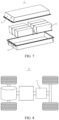
- FIG. 6 and FIG. 7 are schematic diagrams of a battery pack 1 as an example.
- the battery pack 1 may include a battery box and a plurality of battery modules 4 arranged in the battery box.
- the battery box includes an upper box body 2 and a lower box body 3.
- the upper box body 2 is configured to cover the lower box body 3 to form an enclosed space for accommodating the battery modules 4.
- the plurality of battery modules 4 may be arranged in the battery box in any manner.
- the battery may include the battery module or the battery pack.
- An embodiment of this application further provides an electric apparatus.
- the electric apparatus includes at least one of the sodium-ion battery, the battery module, or the battery pack of this application.
- the sodium-ion battery, the battery module, or the battery pack may be used as a power source of the electric apparatus or an energy storage unit of the electric apparatus.
- the electric apparatus may be but is not limited to a mobile device (for example, a mobile phone or a notebook computer), an electric vehicle (for example, a battery electric vehicle, a hybrid electric vehicle, a plug-in hybrid electric vehicle, an electric bicycle, an electric scooter, an electric golf vehicle, or an electric truck), an electric train, a ship, a satellite, or an energy storage system.
- the sodium-ion battery, the battery module, or the battery pack may be selected for the electric apparatus based on requirements for using the electric apparatus.
- FIG. 8 is a schematic diagram of an electric apparatus as an example.
- the electric apparatus is a battery electric vehicle, a hybrid electric vehicle, a plug-in hybrid electric vehicle, or the like.
- a battery pack or a battery module may be used.
- the electric apparatus may be a mobile phone, a tablet computer, a notebook computer, or the like.
- Such electric apparatus is generally required to be light and thin and may use a sodium-ion battery as its power source.
- a 12 ⁇ m thick aluminum foil was used as a positive electrode current collector.
- a positive electrode active substance NaNi 1/3 Co 1/3 Mn 1/3 O 2 , a conductive agent Super P, and a binder polyvinylidene fluoride at a mass ratio of 96.2:2.7: 1.1 were added to N-methylpyrrolidone (NMP) to produce a positive electrode slurry.
- NMP N-methylpyrrolidone
- the positive electrode slurry was applied onto the current collector aluminum foil, and the resulting current collector was dried at 85°C, followed by cold pressing, trimming, cutting, slitting, and drying in vacuum at 85°C for 4 h, to obtain a positive electrode plate.
- An 8 ⁇ m thick copper foil was used as a negative electrode current collector.
- Conductive carbon and a binder styrene-butadiene rubber (SBR) were evenly mixed at a mass ratio of 90:10 in deionized water to produce a conductive slurry, where a solid content of the conductive slurry was 30wt%.
- the conductive slurry was applied onto the negative electrode current collector copper foil, and the resulting current collector was dried at 85°C, followed by cold pressing, trimming, cutting, slitting, and drying in vacuum at 120°C for 12 h, to obtain a negative electrode plate.
- non-aqueous organic solvents diethylene glycol dimethyl ether and triethylene glycol dimethyl ether were mixed at a volume ratio of 1:1 to obtain an electrolyte solvent, and then an electrolytic sodium salt sodium hexafluorophosphate and the mixed solvent were mixed to prepare an electrolyte with a sodium salt concentration of 1 mol/L.
- a 16 ⁇ m thick polyethylene film (PE) was used as a separator.
- the positive electrode plate, the separator, and the negative electrode plate were sequentially stacked so that the separator was located between the positive electrode plate and the negative electrode plate for separation. Then, the resulting stack was wound to obtain an electrode assembly.
- the electrode assembly was placed into an outer package shell and dried, and the electrolyte was then injected, followed by processes such as vacuum sealing, standing, formation, and shaping, to obtain a sodium-ion battery.
- a 12 ⁇ m thick aluminum foil was used as a positive electrode current collector.
- a positive electrode active substance NaNi 1/3 Co 1/3 Mn 1/3 O 2 , a conductive agent Super P, and a binder polyvinylidene fluoride at a mass ratio of 96.2:2.7: 1.1 were added to N-methylpyrrolidone (NMP) to produce a positive electrode slurry.
- NMP N-methylpyrrolidone
- the positive electrode slurry was applied onto the current collector aluminum foil, and the resulting current collector was dried at 85°C, followed by cold pressing, trimming, cutting, slitting, and drying in vacuum at 85°C for 4 h, to obtain a positive electrode plate.
- An 8 ⁇ m thick copper foil was used as a negative electrode current collector.
- PVDF-HFP Polyvinylidene fluoride-hexafluoropropylene copolymer PVDF-HFP was dissolved in N-methylpyrrolidone NMP at a material-to-liquid ratio of 1:100 g/ml, and then mixed with a sodium salt (sodium hexafluorophosphate) at a molar ratio of a total molar amount of VDF and HFP to Na + being 10:1. The mixture was subjected to high-temperature drying at > 80°C for 12 h to obtain a PVDF-HFP solid electrolyte.
- sodium salt sodium hexafluorophosphate
- the positive electrode plate, the solid electrolyte, and the negative electrode plate were sequentially stacked so that the solid electrolyte was located between the positive electrode plate and the negative electrode plate. Then, the resulting stack was wound and placed into an outer package shell, followed by processes such as vacuum sealing, standing, formation, and shaping, to obtain a sodium-ion battery.
- a 12 ⁇ m thick aluminum foil was used as a positive electrode current collector.
- a positive electrode active substance NaNi 1/3 Co 1/3 Mn 1/3 O 2 , a conductive agent Super P, and a binder polyvinylidene fluoride at a mass ratio of 96.2:2.7:1.1 were added to N-methylpyrrolidone (NMP) to produce a positive electrode slurry.
- NMP N-methylpyrrolidone
- the positive electrode slurry was applied onto the current collector aluminum foil, and the resulting current collector was dried at 85°C, followed by cold pressing, trimming, cutting, slitting, and drying in vacuum at 85°C for 4 h, to obtain a positive electrode plate.
- An 8 ⁇ m thick copper foil was used as a negative electrode current collector.
- Polyethylene oxide PEO was dissolved in DMF at a material-to-liquid ratio of 1:100 g/ml, and then mixed with a sodium salt at a molar ratio of EO to Na + being 10:1. The mixture was subjected to high-temperature drying at > 80°C for 12 h to obtain a PEO-based solid electrolyte.
- the positive electrode plate, the ion conductor, and the negative electrode plate were sequentially stacked so that the ion conductor was located between the positive electrode plate and the negative electrode plate for separation. Then, the resulting stack was wound to obtain an electrode assembly.
- the electrode assembly was placed into an outer package shell, followed by processes such as vacuum sealing, standing, formation, and shaping, to obtain a sodium-ion battery.
- Example 1-1 Different from Example 1-1, the ion conductor used different materials, and the specific preparation steps were as follows.
- Polyethylene oxide PEO-polyvinylidene fluoride PVDF was dissolved in N,N-dimethylformamide DMF at a material-to-liquid ratio of 1:100 g/ml, and then mixed with a sodium salt (sodium hexafluorophosphate) at a molar ratio of a total molar amount of ethylene oxide EO and vinylidene fluoride VDF to Na + being 10:1.
- the mixture was subjected to high-temperature drying at > 80°C for 12 h to obtain a polyethylene oxide PEO-polyvinylidene fluoride PVDF-based solid electrolyte.
- Example 1-1 Different from Example 1-1, the ion conductor used different materials, and the specific preparation steps were as follows.
- Polyvinylidene fluoride PVDF was dissolved in DMF at a material-to-liquid ratio of 1:100 g/ml, and then mixed with a sodium salt at a molar ratio of VDF to Na + being 10:1. The mixture was subjected to high-temperature drying at > 80°C for 12 h to obtain a PVDF-based solid electrolyte.
- a 12 ⁇ m thick aluminum foil was used as a positive electrode current collector.
- a positive electrode active substance NaNi 1/3 Co 1/3 Mn 1/3 O 2 , a conductive agent Super P, and a binder polyvinylidene fluoride at a mass ratio of 96.2:2.7: 1.1 were added to N-methylpyrrolidone (NMP) to produce a positive electrode slurry.
- NMP N-methylpyrrolidone
- the positive electrode slurry was applied onto the current collector aluminum foil, and the resulting current collector was dried at 85°C, followed by cold pressing, trimming, cutting, slitting, and drying in vacuum at 85°C for 4 h, to obtain a positive electrode plate.
- An 8 ⁇ m thick copper foil was used as a negative electrode current collector.
- Polymethyl methacrylate PMMA was used as a gel base solution, PMMA particles were dissolved in a DMF solvent at a material-to-liquid ratio of 1:5, and the mixture was placed into a mold and dried for 12 h to obtain a gel system.
- the positive electrode plate and the negative electrode plate were sequentially stacked, and then wound to obtain an electrode assembly.
- the electrode assembly was placed into an outer package shell, the gel system was added to the outer package, and an electrolyte was injected for infiltration for 4 h, to obtain a sodium-ion battery.
- Preparation of the electrolyte was as follows: In an environment with a water content less than 10 ppm, non-aqueous organic solvents diethylene glycol dimethyl ether and triethylene glycol dimethyl ether were mixed at a volume ratio of 1:1 to obtain an electrolyte solvent, and then an electrolytic sodium salt sodium hexafluorophosphate and the mixed solvent were mixed to prepare an electrolyte with a sodium salt concentration of 1 mol/L.
- Example 2-1 Different from Example 2-1, the ion conductor used different materials, and the specific preparation steps of the sodium-ion battery were as follows: Polyacrylonitrile PAN was used as a gel base solution, PAN particles were dissolved in a DMF solvent at a material-to-liquid ratio of 1:5, and the mixture was placed into a mold and dried for 12 h to obtain a gel system.
- Polyacrylonitrile PAN was used as a gel base solution
- PAN particles were dissolved in a DMF solvent at a material-to-liquid ratio of 1:5
- the mixture was placed into a mold and dried for 12 h to obtain a gel system.
- the positive electrode plate and the negative electrode plate were sequentially stacked, and then wound to obtain an electrode assembly.
- the electrode assembly was placed into an outer package shell, the gel system was added to the outer package, and the electrolyte was injected for infiltration for 4 h, to obtain a sodium-ion battery.
- a 12 ⁇ m thick aluminum foil was used as a positive electrode current collector.
- a positive electrode active substance NaNi 1/3 Co 1/3 Mn 1/3 O 2 , a conductive agent Super P, and a binder polyvinylidene fluoride at a mass ratio of 96.2:2.7: 1.1 were added to N-methylpyrrolidone (NMP) to produce a positive electrode slurry.
- NMP N-methylpyrrolidone
- the positive electrode slurry was applied onto the current collector aluminum foil, and the resulting current collector was dried at 85°C, followed by cold pressing, trimming, cutting, slitting, and drying in vacuum at 85°C for 4 h, to obtain a positive electrode plate.
- An 8 ⁇ m thick copper foil was used as a negative electrode current collector.
- the positive electrode plate, a polyethylene film, and the negative electrode plate were sequentially stacked so that the polyethylene film was located between the positive electrode plate and the negative electrode plate for separation. Then, the resulting stack was wound to obtain an electrode assembly.
- the electrode assembly was placed into an outer package shell and dried, methyl methacrylate MMA and an electrolyte (at a ratio of > 1:4) were injected, and a thermal initiator azobisisobutyronitrile AIBN was added to form an electrolyte system.
- the mixed electrolyte system was used to infiltrate the separator, followed by processes such as heat curing at > 50°C, vacuum sealing, standing, formation, and shaping, to obtain a sodium-ion battery.
- the ion conductor used different materials, and the specific preparation steps of the sodium-ion battery were as follows: The positive electrode plate, a polyethylene film, and the negative electrode plate were sequentially stacked so that the polyethylene film was located between the positive electrode plate and the negative electrode plate for separation. Then, the resulting stack was wound to obtain an electrode assembly.
- the electrode assembly was placed into an outer package shell and dried, acrylonitrile AN and an electrolyte (at a ratio of > 1:4) were injected, and a thermal initiator azobisisobutyronitrile AIBN was added to form an electrolyte system.
- the mixed electrolyte system was used to infiltrate the separator, followed by processes such as heat curing at > 50°C, vacuum sealing, standing, formation, and shaping, to obtain a sodium-ion battery.
- a 12 ⁇ m thick aluminum foil was used as a positive electrode current collector.
- a positive electrode active substance NaNi 1/3 Co 1/3 Mn 1/3 O 2 , a conductive agent Super P, and a binder polyvinylidene fluoride at a mass ratio of 96.2:2.7: 1.1 were added to N-methylpyrrolidone (NMP) to produce a positive electrode slurry.
- NMP N-methylpyrrolidone
- the positive electrode slurry was applied onto the current collector aluminum foil, and the resulting current collector was dried at 85°C, followed by cold pressing, trimming, cutting, slitting, and drying in vacuum at 85°C for 4 h, to obtain a positive electrode plate.
- An 8 ⁇ m thick copper foil was used as a negative electrode current collector.
- Polyethylene oxide PEO was dissolved in N,N-dimethylformamide DMF at a material-to-liquid ratio of 1:100 g/ml, and then mixed with a sodium salt at a molar ratio of ethylene oxide EO to Na + being 10:1. The mixture was subjected to high-temperature drying at > 80°C for 12 h to obtain a PEO-based solid electrolyte.
- non-aqueous organic solvents diethylene glycol dimethyl ether and triethylene glycol dimethyl ether were mixed at a volume ratio of 1:1 to obtain an electrolyte solvent, and then an electrolytic sodium salt sodium hexafluorophosphate and the mixed solvent were mixed to prepare an electrolyte with a sodium salt concentration of 1 mol/L.
- the positive electrode plate, the ion conductor, and the negative electrode plate were sequentially stacked so that the ion conductor was located between the positive electrode plate and the negative electrode plate for separation. Then, the resulting stack was wound to obtain an electrode assembly.
- the electrode assembly was placed into an outer package shell and dried, and the electrolyte was then injected, followed by processes such as vacuum sealing, standing, formation, and shaping, to obtain a sodium-ion battery.
- a 12 ⁇ m thick aluminum foil was used as a positive electrode current collector.
- a positive electrode active substance NaNi 1/3 Co 1/3 Mn 1/3 O 2 , a conductive agent Super P, and a binder polyvinylidene fluoride at a mass ratio of 96.2:2.7: 1.1 were added to N-methylpyrrolidone (NMP) to produce a positive electrode slurry.
- NMP N-methylpyrrolidone
- the positive electrode slurry was applied onto the current collector aluminum foil, and the resulting current collector was dried at 85°C, followed by cold pressing, trimming, cutting, slitting, and drying in vacuum at 85°C for 4 h, to obtain a positive electrode plate.
- An 8 ⁇ m thick copper foil was used as a negative electrode current collector.
- Polyethylene oxide PEO was dissolved in N,N-dimethylformamide DMF at a material-to-liquid ratio of 1:100 g/ml, and then mixed with a sodium salt at a molar ratio of ethylene oxide EO to Na + being 10:1. The mixture was subjected to high-temperature drying at > 80°C for 12 h to obtain a PEO-based solid electrolyte.
- the positive electrode plate, the ion conductor, and the negative electrode plate were sequentially stacked so that the ion conductor was located between the positive electrode plate and the negative electrode plate for separation. Then, the resulting stack was wound to obtain an electrode assembly.
- the electrode assembly was placed into an outer package shell, followed by processes such as vacuum sealing, standing, formation, and shaping, to obtain a sodium-ion battery.
- the positive electrode plate, the ion conductor, and the negative electrode plate were sequentially stacked so that the ion conductor was located between the positive electrode plate and the negative electrode plate for separation. Then, the resulting stack was wound to obtain an electrode assembly.
- a mixed solution of polyvinylidene fluoride and silicon oxide was sprayed onto an end portion of the electrode assembly, and cured and dried to form an insulating structure.
- the electrode assembly was placed into an outer package shell, followed by processes such as vacuum sealing, standing, formation, and shaping, to obtain a sodium-ion battery.
- the prepared secondary battery was charged to a charge cut-off voltage of 4.4 V at a constant current of 0.33C, then charged to a current of 0.05C at a constant voltage, left standing for 5 min, and discharged to a discharge cut-off voltage of 2.8 V at a constant current of 0.33C.
- An initial capacity of the battery was recorded as C0.
- the battery was charged according to the strategy in Table 4, and discharged at 0.33C.
- a discharge capacity Cn after each cycle was recorded until a cycling capacity retention rate (that is, Cn/C0 ⁇ 100%) was 80%, and the number of cycles was recorded. More cycles indicate better cycling performance of the secondary battery.
- Table 1 State of charge SOC of secondary battery Charging rate (C) 0-10% 0.33 10%-20% 5.2 20%-30% 4.5 30%-40% 4.2 40%-50% 3.3 50%-60% 2.6 60%-70% 2.0 70%-80% 1.5 80%-100% 0.33
- Comparative Example 1 uses a conventional liquid electrolyte. During charging of the sodium-ion battery, the sodium metal deposited on the surface of the negative electrode current collector is likely to be squeezed to the end portion of the negative electrode plate, which increases the risk of short-circuiting between the negative electrode plate and the positive electrode plate, resulting in poor safety performance of the sodium-ion battery.
- Comparative Example 2 uses a solid polymer electrolyte. Sodium ions migrate to the surface of the negative electrode current collector through the solid polymer electrolyte and deposit as sodium metal. Because the elastic modulus of such solid polymer electrolyte is relatively high and greater than 5.0 GPa, as the amount of the deposited sodium metal increases, the sodium metal is still squeezed to the end portion of the negative electrode plate, which causes short-circuiting between the negative electrode plate and the positive electrode plate, resulting in poor cycling performance.
- the ion conductor disposed in the embodiments of this application can provide migration paths for sodium ions.
- the ion conductor has excellent elasticity, with an elastic modulus of 0.1 GPa to 5.0 GPa, which allows it to deform correspondingly in regions with increased precipitated sodium metal, reduces the risk of the sodium metal being squeezed out, and reduces the risk of short circuit caused by contact between the squeezed-out sodium metal and the positive electrode plate, thereby improving the safety performance of the sodium-ion battery and improving the cycling performance of the sodium-ion battery.
- the ion conductor can be used in various forms, such as a solid electrolyte, a gel electrolyte, and a composite form of a supporting layer and a conducting layer.
- the elastic moduli of these ion conductors differ slightly, they all have deformability, which can improve the safety performance.
- the extent to which the ion conductor improves the safety performance of the sodium-ion battery is still related to the range of the elastic modulus.
Landscapes
- Chemical & Material Sciences (AREA)
- Chemical Kinetics & Catalysis (AREA)
- Electrochemistry (AREA)
- General Chemical & Material Sciences (AREA)
- Engineering & Computer Science (AREA)
- Manufacturing & Machinery (AREA)
- Condensed Matter Physics & Semiconductors (AREA)
- Dispersion Chemistry (AREA)
- General Physics & Mathematics (AREA)
- Inorganic Chemistry (AREA)
- Physics & Mathematics (AREA)
- Materials Engineering (AREA)
- Secondary Cells (AREA)
- Battery Electrode And Active Subsutance (AREA)
Applications Claiming Priority (2)
| Application Number | Priority Date | Filing Date | Title |
|---|---|---|---|
| CN202211676739.5A CN118263508A (zh) | 2022-12-26 | 2022-12-26 | 钠离子电池、电池和用电装置 |
| PCT/CN2023/113023 WO2024139249A1 (zh) | 2022-12-26 | 2023-08-15 | 钠离子电池、电池和用电装置 |
Publications (2)
| Publication Number | Publication Date |
|---|---|
| EP4517993A1 true EP4517993A1 (de) | 2025-03-05 |
| EP4517993A4 EP4517993A4 (de) | 2025-09-10 |
Family
ID=91609597
Family Applications (1)
| Application Number | Title | Priority Date | Filing Date |
|---|---|---|---|
| EP23909190.3A Pending EP4517993A4 (de) | 2022-12-26 | 2023-08-15 | Natriumionenbatterie, batterie und elektrische vorrichtung |
Country Status (4)
| Country | Link |
|---|---|
| US (1) | US20250087837A1 (de) |
| EP (1) | EP4517993A4 (de) |
| CN (1) | CN118263508A (de) |
| WO (1) | WO2024139249A1 (de) |
Families Citing this family (1)
| Publication number | Priority date | Publication date | Assignee | Title |
|---|---|---|---|---|
| CN121416592A (zh) * | 2024-07-25 | 2026-01-27 | 宁德时代新能源科技股份有限公司 | 钠金属电池及其制备方法、用电装置 |
Family Cites Families (6)
| Publication number | Priority date | Publication date | Assignee | Title |
|---|---|---|---|---|
| JP6574615B2 (ja) * | 2015-06-02 | 2019-09-11 | シャープ株式会社 | 金属電極カートリッジ、及び、化学電池 |
| JP6856042B2 (ja) * | 2018-03-06 | 2021-04-07 | トヨタ自動車株式会社 | 全固体電池 |
| JP2021044131A (ja) * | 2019-09-10 | 2021-03-18 | トヨタ自動車株式会社 | 非水電解質二次電池 |
| CN113270689B (zh) * | 2021-05-25 | 2023-04-07 | 郑州大学 | 一种高安全电池隔膜及制备方法 |
| CN114188658B (zh) * | 2021-11-15 | 2024-12-10 | 深圳中兴新材技术股份有限公司 | 一种薄膜及其制备方法与电池 |
| CN115425287B (zh) * | 2022-09-30 | 2025-03-18 | 北京化工大学 | 一种含合金型负极和弹性电解质的全固态电池 |
-
2022
- 2022-12-26 CN CN202211676739.5A patent/CN118263508A/zh active Pending
-
2023
- 2023-08-15 EP EP23909190.3A patent/EP4517993A4/de active Pending
- 2023-08-15 WO PCT/CN2023/113023 patent/WO2024139249A1/zh not_active Ceased
-
2024
- 2024-11-27 US US18/962,978 patent/US20250087837A1/en active Pending
Also Published As
| Publication number | Publication date |
|---|---|
| CN118263508A (zh) | 2024-06-28 |
| WO2024139249A1 (zh) | 2024-07-04 |
| US20250087837A1 (en) | 2025-03-13 |
| EP4517993A4 (de) | 2025-09-10 |
Similar Documents
| Publication | Publication Date | Title |
|---|---|---|
| KR102502618B1 (ko) | 이차 전지, 이차 전지를 포함하는 전지 모듈, 전지 팩 및 장치 | |
| US20220328831A1 (en) | Secondary battery, preparation method thereof, and battery module, battery pack, and apparatus associated therewith | |
| CN118899512B (zh) | 二次电池与含有该二次电池的电池模块、电池包和用电装置 | |
| EP3800707B1 (de) | Sekundärbatterie und entsprechendes batteriemodul, batteriepack und gerät | |
| KR102889485B1 (ko) | 전해액, 이차 전지, 전지 모듈, 전지 팩 및 전기 장치 | |
| KR102907530B1 (ko) | 전극판, 이차 전지, 그 제조 방법 및 이차 전지를 포함하는 장치 | |
| KR102677615B1 (ko) | 전해액 및 전기화학장치 | |
| KR102864154B1 (ko) | 리튬 이차전지 | |
| EP4503173A1 (de) | Negativelektrodenplatte und herstellungsverfahren dafür, sekundärbatterie, batteriemodul, batteriepack und elektrische vorrichtung | |
| US20250070275A1 (en) | Negative electrode plate, secondary battery and electrical apparatus | |
| US20250219151A1 (en) | Sodium secondary battery, battery module, battery pack, and electric apparatus | |
| US20250349970A1 (en) | Secondary battery and electric apparatus | |
| EP4693686A1 (de) | Separator und herstellungsverfahren dafür, batterie und elektrische vorrichtung | |
| US20250087837A1 (en) | Sodium-ion battery, battery, and electric apparatus | |
| KR102722692B1 (ko) | 이차 전지 및 이를 포함하는 장치 | |
| JP7674463B2 (ja) | 負極極板、二次電池、電池モジュール、電池パックと電力消費装置 | |
| CN121035225A (zh) | 二次电池及其制备方法、聚合物基集流体和用电装置 | |
| US20240372158A1 (en) | Secondary battery, battery module, battery pack, and electrical device | |
| KR102816873B1 (ko) | 전해액, 이차 전지, 전지 모듈, 전지 팩 및 장치 | |
| KR20230172520A (ko) | 전해액, 이차 전지, 전지 모듈, 전지 팩 및 전기 장치 | |
| WO2024000095A1 (zh) | 负极极片、二次电池、电池模组、电池包及用电装置 | |
| US12034155B1 (en) | Secondary battery and electrical device | |
| EP4496033A1 (de) | Positivelektrodenaktivmaterial, herstellungsverfahren, sekundärbatterie und elektrische vorrichtung | |
| EP4510212A1 (de) | Negativelektrodenfolie und herstellungsverfahren dafür, sekundärbatterie, batteriepack und elektrische vorrichtung | |
| WO2026026803A1 (zh) | 隔离膜及其制备方法、电池单体、电池装置、用电装置 |
Legal Events
| Date | Code | Title | Description |
|---|---|---|---|
| STAA | Information on the status of an ep patent application or granted ep patent |
Free format text: STATUS: THE INTERNATIONAL PUBLICATION HAS BEEN MADE |
|
| PUAI | Public reference made under article 153(3) epc to a published international application that has entered the european phase |
Free format text: ORIGINAL CODE: 0009012 |
|
| STAA | Information on the status of an ep patent application or granted ep patent |
Free format text: STATUS: REQUEST FOR EXAMINATION WAS MADE |
|
| 17P | Request for examination filed |
Effective date: 20241128 |
|
| AK | Designated contracting states |
Kind code of ref document: A1 Designated state(s): AL AT BE BG CH CY CZ DE DK EE ES FI FR GB GR HR HU IE IS IT LI LT LU LV MC ME MK MT NL NO PL PT RO RS SE SI SK SM TR |
|
| A4 | Supplementary search report drawn up and despatched |
Effective date: 20250808 |
|
| RIC1 | Information provided on ipc code assigned before grant |
Ipc: H01M 50/414 20210101AFI20250804BHEP Ipc: H01M 50/489 20210101ALI20250804BHEP Ipc: H01M 10/054 20100101ALI20250804BHEP Ipc: H01M 50/586 20210101ALI20250804BHEP Ipc: H01M 50/449 20210101ALI20250804BHEP Ipc: H01M 10/0565 20100101ALI20250804BHEP |
|
| DAV | Request for validation of the european patent (deleted) | ||
| DAX | Request for extension of the european patent (deleted) |