EP4517907A1 - Elektrodenanordnung und elektrochemische vorrichtung damit - Google Patents
Elektrodenanordnung und elektrochemische vorrichtung damit Download PDFInfo
- Publication number
- EP4517907A1 EP4517907A1 EP23880295.3A EP23880295A EP4517907A1 EP 4517907 A1 EP4517907 A1 EP 4517907A1 EP 23880295 A EP23880295 A EP 23880295A EP 4517907 A1 EP4517907 A1 EP 4517907A1
- Authority
- EP
- European Patent Office
- Prior art keywords
- electrode assembly
- wrapping
- negative electrode
- portions
- stack
- Prior art date
- Legal status (The legal status is an assumption and is not a legal conclusion. Google has not performed a legal analysis and makes no representation as to the accuracy of the status listed.)
- Pending
Links
Images


Classifications
-
- H—ELECTRICITY
- H01—ELECTRIC ELEMENTS
- H01M—PROCESSES OR MEANS, e.g. BATTERIES, FOR THE DIRECT CONVERSION OF CHEMICAL ENERGY INTO ELECTRICAL ENERGY
- H01M10/00—Secondary cells; Manufacture thereof
- H01M10/05—Accumulators with non-aqueous electrolyte
- H01M10/058—Construction or manufacture
- H01M10/0583—Construction or manufacture of accumulators with folded construction elements except wound ones, i.e. folded positive or negative electrodes or separators, e.g. with "Z"-shaped electrodes or separators
-
- H—ELECTRICITY
- H01—ELECTRIC ELEMENTS
- H01M—PROCESSES OR MEANS, e.g. BATTERIES, FOR THE DIRECT CONVERSION OF CHEMICAL ENERGY INTO ELECTRICAL ENERGY
- H01M10/00—Secondary cells; Manufacture thereof
- H01M10/04—Construction or manufacture in general
- H01M10/0431—Cells with wound or folded electrodes
-
- H—ELECTRICITY
- H01—ELECTRIC ELEMENTS
- H01M—PROCESSES OR MEANS, e.g. BATTERIES, FOR THE DIRECT CONVERSION OF CHEMICAL ENERGY INTO ELECTRICAL ENERGY
- H01M10/00—Secondary cells; Manufacture thereof
- H01M10/04—Construction or manufacture in general
- H01M10/045—Cells or batteries with folded plate-like electrodes
-
- H—ELECTRICITY
- H01—ELECTRIC ELEMENTS
- H01M—PROCESSES OR MEANS, e.g. BATTERIES, FOR THE DIRECT CONVERSION OF CHEMICAL ENERGY INTO ELECTRICAL ENERGY
- H01M10/00—Secondary cells; Manufacture thereof
- H01M10/05—Accumulators with non-aqueous electrolyte
- H01M10/052—Li-accumulators
-
- H—ELECTRICITY
- H01—ELECTRIC ELEMENTS
- H01M—PROCESSES OR MEANS, e.g. BATTERIES, FOR THE DIRECT CONVERSION OF CHEMICAL ENERGY INTO ELECTRICAL ENERGY
- H01M4/00—Electrodes
- H01M4/02—Electrodes composed of, or comprising, active material
- H01M4/13—Electrodes for accumulators with non-aqueous electrolyte, e.g. for lithium-accumulators; Processes of manufacture thereof
- H01M4/134—Electrodes based on metals, Si or alloys
-
- H—ELECTRICITY
- H01—ELECTRIC ELEMENTS
- H01M—PROCESSES OR MEANS, e.g. BATTERIES, FOR THE DIRECT CONVERSION OF CHEMICAL ENERGY INTO ELECTRICAL ENERGY
- H01M4/00—Electrodes
- H01M4/02—Electrodes composed of, or comprising, active material
- H01M4/36—Selection of substances as active materials, active masses, active liquids
- H01M4/38—Selection of substances as active materials, active masses, active liquids of elements or alloys
- H01M4/381—Alkaline or alkaline earth metals elements
- H01M4/382—Lithium
-
- H—ELECTRICITY
- H01—ELECTRIC ELEMENTS
- H01M—PROCESSES OR MEANS, e.g. BATTERIES, FOR THE DIRECT CONVERSION OF CHEMICAL ENERGY INTO ELECTRICAL ENERGY
- H01M4/00—Electrodes
- H01M4/02—Electrodes composed of, or comprising, active material
- H01M4/36—Selection of substances as active materials, active masses, active liquids
- H01M4/48—Selection of substances as active materials, active masses, active liquids of inorganic oxides or hydroxides
- H01M4/50—Selection of substances as active materials, active masses, active liquids of inorganic oxides or hydroxides of manganese
- H01M4/505—Selection of substances as active materials, active masses, active liquids of inorganic oxides or hydroxides of manganese of mixed oxides or hydroxides containing manganese for inserting or intercalating light metals, e.g. LiMn2O4 or LiMn2OxFy
-
- H—ELECTRICITY
- H01—ELECTRIC ELEMENTS
- H01M—PROCESSES OR MEANS, e.g. BATTERIES, FOR THE DIRECT CONVERSION OF CHEMICAL ENERGY INTO ELECTRICAL ENERGY
- H01M4/00—Electrodes
- H01M4/02—Electrodes composed of, or comprising, active material
- H01M4/36—Selection of substances as active materials, active masses, active liquids
- H01M4/48—Selection of substances as active materials, active masses, active liquids of inorganic oxides or hydroxides
- H01M4/52—Selection of substances as active materials, active masses, active liquids of inorganic oxides or hydroxides of nickel, cobalt or iron
- H01M4/525—Selection of substances as active materials, active masses, active liquids of inorganic oxides or hydroxides of nickel, cobalt or iron of mixed oxides or hydroxides containing iron, cobalt or nickel for inserting or intercalating light metals, e.g. LiNiO2, LiCoO2 or LiCoOxFy
-
- H—ELECTRICITY
- H01—ELECTRIC ELEMENTS
- H01M—PROCESSES OR MEANS, e.g. BATTERIES, FOR THE DIRECT CONVERSION OF CHEMICAL ENERGY INTO ELECTRICAL ENERGY
- H01M50/00—Constructional details or processes of manufacture of the non-active parts of electrochemical cells other than fuel cells, e.g. hybrid cells
- H01M50/40—Separators; Membranes; Diaphragms; Spacing elements inside cells
- H01M50/463—Separators, membranes or diaphragms characterised by their shape
- H01M50/466—U-shaped, bag-shaped or folded
-
- H—ELECTRICITY
- H01—ELECTRIC ELEMENTS
- H01M—PROCESSES OR MEANS, e.g. BATTERIES, FOR THE DIRECT CONVERSION OF CHEMICAL ENERGY INTO ELECTRICAL ENERGY
- H01M50/00—Constructional details or processes of manufacture of the non-active parts of electrochemical cells other than fuel cells, e.g. hybrid cells
- H01M50/50—Current conducting connections for cells or batteries
- H01M50/572—Means for preventing undesired use or discharge
- H01M50/584—Means for preventing undesired use or discharge for preventing incorrect connections inside or outside the batteries
- H01M50/586—Means for preventing undesired use or discharge for preventing incorrect connections inside or outside the batteries inside the batteries, e.g. incorrect connections of electrodes
-
- H—ELECTRICITY
- H01—ELECTRIC ELEMENTS
- H01M—PROCESSES OR MEANS, e.g. BATTERIES, FOR THE DIRECT CONVERSION OF CHEMICAL ENERGY INTO ELECTRICAL ENERGY
- H01M50/00—Constructional details or processes of manufacture of the non-active parts of electrochemical cells other than fuel cells, e.g. hybrid cells
- H01M50/50—Current conducting connections for cells or batteries
- H01M50/572—Means for preventing undesired use or discharge
- H01M50/584—Means for preventing undesired use or discharge for preventing incorrect connections inside or outside the batteries
- H01M50/59—Means for preventing undesired use or discharge for preventing incorrect connections inside or outside the batteries characterised by the protection means
- H01M50/595—Tapes
-
- H—ELECTRICITY
- H01—ELECTRIC ELEMENTS
- H01M—PROCESSES OR MEANS, e.g. BATTERIES, FOR THE DIRECT CONVERSION OF CHEMICAL ENERGY INTO ELECTRICAL ENERGY
- H01M4/00—Electrodes
- H01M4/02—Electrodes composed of, or comprising, active material
- H01M2004/021—Physical characteristics, e.g. porosity, surface area
-
- H—ELECTRICITY
- H01—ELECTRIC ELEMENTS
- H01M—PROCESSES OR MEANS, e.g. BATTERIES, FOR THE DIRECT CONVERSION OF CHEMICAL ENERGY INTO ELECTRICAL ENERGY
- H01M4/00—Electrodes
- H01M4/02—Electrodes composed of, or comprising, active material
- H01M2004/026—Electrodes composed of, or comprising, active material characterised by the polarity
- H01M2004/027—Negative electrodes
-
- Y—GENERAL TAGGING OF NEW TECHNOLOGICAL DEVELOPMENTS; GENERAL TAGGING OF CROSS-SECTIONAL TECHNOLOGIES SPANNING OVER SEVERAL SECTIONS OF THE IPC; TECHNICAL SUBJECTS COVERED BY FORMER USPC CROSS-REFERENCE ART COLLECTIONS [XRACs] AND DIGESTS
- Y02—TECHNOLOGIES OR APPLICATIONS FOR MITIGATION OR ADAPTATION AGAINST CLIMATE CHANGE
- Y02E—REDUCTION OF GREENHOUSE GAS [GHG] EMISSIONS, RELATED TO ENERGY GENERATION, TRANSMISSION OR DISTRIBUTION
- Y02E60/00—Enabling technologies; Technologies with a potential or indirect contribution to GHG emissions mitigation
- Y02E60/10—Energy storage using batteries
-
- Y—GENERAL TAGGING OF NEW TECHNOLOGICAL DEVELOPMENTS; GENERAL TAGGING OF CROSS-SECTIONAL TECHNOLOGIES SPANNING OVER SEVERAL SECTIONS OF THE IPC; TECHNICAL SUBJECTS COVERED BY FORMER USPC CROSS-REFERENCE ART COLLECTIONS [XRACs] AND DIGESTS
- Y02—TECHNOLOGIES OR APPLICATIONS FOR MITIGATION OR ADAPTATION AGAINST CLIMATE CHANGE
- Y02P—CLIMATE CHANGE MITIGATION TECHNOLOGIES IN THE PRODUCTION OR PROCESSING OF GOODS
- Y02P70/00—Climate change mitigation technologies in the production process for final industrial or consumer products
- Y02P70/50—Manufacturing or production processes characterised by the final manufactured product
Definitions
- the present invention relates to an electrode assembly and an electrochemical device comprising same. More particularly, the present invention relates to an electrode assembly comprising lithium metal in a negative electrode and an electrochemical device comprising same.
- Electrodes are also categorized by the structure of the electrode assembly consisting of positive electrode/separating film/negative electrode.
- electrode assemblies are categorized into jelly-roll (wound) electrode assemblies, which are the wound long sheet of positive electrodes and negative electrodes with separating films, and stacked electrode assemblies, wherein multiple positive electrodes and negative electrodes cut into predetermined sized units with separating films are stacked sequentially.
- the jelly-roll electrode assembly is made by winding the long sheet of positive electrodes and negative electrodes in a dense state, thereby to have a cylindrical or elliptical cross-section.
- stresses caused by the expansion and contraction of the electrodes during charge and discharge accumulate in the electrode assembly, and when such stress accumulation exceeds a certain limit, deformation of the electrode assembly occurs.
- the deformation of the electrode assembly may cause uneven spacing between the electrodes, resulting in a sharp decrease in the performance of the battery, and an internal short circuit may occur, threatening the safety of the battery.
- the jelly-roll electrode assembly requires winding a long sheet of the positive electrodes and negative electrodes, it is difficult to wind the positive electrodes and negative electrodes quickly while maintaining a constant spacing between the positive electrodes and negative electrodes, resulting in a decrease in productivity.
- the stackable electrode assembly requires sequential stacking of multiple positive electrode units and negative electrode units. In this process, since a separate electrode plate transfer process is required to manufacture the unit, and the sequential stacking process requires a lot of time and effort, the stackable electrode assembly has the problem of low productivity.
- the stackable-foldable electrode assembly has a structure in which bi-cells or full cells stacked with separating films between the positive electrodes and negative electrodes of a predetermined unit are wound using a long continuous separating film sheet (foldable separating film).
- the stackable-foldable electrode assembly typically connects the electrodes of each layer by extending separating films that are easier to fold, rather than extending the electrodes. In this process, the electrodes of each layer are supplied in a cut state for formation of the electrode assembly, as in the stacked electrode assembly.
- the general stackable-foldable electrode assembly is more suitable.
- lithium metal which is well-known as a negative electrode material for secondary batteries in the art, may not be suitable for conventional stackable-foldable electrode assemblies because it is not easy to be processed by, such as, cutting, due to its physical properties such as high ductile and viscosity, and it is relatively easy to be folded.
- the inventor(s) of the present invention After continuous research on the structure of electrode assemblies, the inventor(s) of the present invention has designed a structure suitable for electrode assemblies, especially containing lithium metal as a negative electrode, and has completed the present invention.
- Patent reference 1 Korean Patent No. 10-2023530
- the present invention seeks to provide an electrode assembly with a novel structure suitable for an electrode assembly comprising lithium metal as a negative electrode, and an electrochemical device comprising same.
- the present invention provides an electrode assembly comprising a negative electrode structure and a plurality of positive electrodes.
- the negative electrode structure includes first and second separating films, and a lithium metal layer interposed between the first and second separating films.
- the negative electrode structure is divided into a plurality of stack portions, a plurality of folding portions, and first and second wrapping portions in accordance with their positions in the electrode assembly.
- the stack portion and the folding portion are located alternately between the first and second wrapping portions located at the end portion, respectively, of the negative electrode structure, wherein the first and second wrapping portions abut the stack portion, respectively.
- the electrode assembly has the plurality of stack portions sequentially positioned side-by-side in the thickness direction by the folding portion, and at least one positive electrode is positioned between the stack portions, which are adjacent to each other in the thickness direction.
- the electrode assembly has a structure in which the outer faces in the thickness direction and the longitudinal direction are surrounded by first and second wrapping portions, or first and second wrapping portions and at least one outermost stack portion.
- the plurality of stack portions and the plurality of positive electrodes become closer to each other in the thickness direction by the wrapping portion.
- the first wrapping portion and the second wrapping portion do not overlap each other.
- the first wrapping portion and the second wrapping portion have the same length as each other.
- the first wrapping portion and the second wrapping portion are secured to different outermost stack portions.
- one positive electrode is located between the stack portions adjacent to each other in the thickness direction, and a total number of positive electrodes located between the stack portions is 2n (wherein n is a natural number).
- the positive electrode in the electrode assembly, includes a positive electrode active material layer, and a current collector supporting the positive electrode active material layer, and the negative electrode structure does not include a current collector supporting a lithium metal layer.
- the lengths of the lithium metal layer and the first and second separating films are the same.
- an end of the first wrapping portion is located on a stack portion abutting the second wrapping portion such that the first wrapping portion turns to wrap around one side of the adjacent electrode assembly
- an end of the second wrapping portion is located on a stack portion abutting the first wrapping portion such that the second wrapping portion turns to wrap around one side of the adjacent electrode assembly.
- the electrode assembly further comprises a fixing member securing an end of each of the first and second wrapping portions to the outermost stack portion.
- the length of the folding portion in the negative electrode structure is from 2 to 10 times the sum of the thicknesses of the positive electrode and the negative electrode structure.
- the length of the folding portion in the negative electrode structure is from 2 to 10 times the vertical distance between the end of the positive electrode and the lateral wrapping portion surrounding it.
- the folding portion has an asymmetrical shape with respect to a plane along the longitudinal direction.
- the thickness of the lithium metal layer in the negative electrode structure is from 50% to 90% based on the overall thickness of the negative electrode structure.
- the thickness of the positive electrode is greater than the thickness of the negative electrode structure.
- the fixing member is an insulating tape.
- a center point of the length of the folding portion is not aligned with a center point of the thickness of the positive electrode that the folding portion surrounds.
- the first wrapping portion and the second wrapping portion, each located on the stack portion do not overlap each other in the thickness direction.
- the first wrapping portion and the second wrapping portion, each located on the stack portion overlap each other in the thickness direction.
- the end of the first wrapping portion and the end of the second wrapping portion are located on the same line in the thickness direction.
- the present invention provides an electrochemical device comprising the electrode assembly described above.
- the electrochemical device is a lithium secondary battery.
- the electrochemical device is a lithium-sulfur battery.
- An electrode assembly according to one embodiment of the present invention is manufactured by utilizing one negative electrode structure in a continuous form interposed between two separating films with a negative electrode comprising lithium metal, thereby minimizing the cutting of lithium metal, and accordingly, improving process efficiency in manufacturing an electrode assembly.
- the manufactured electrode assembly has a stable structure, but also the performance of the battery can be improved.
- first, second, A, B, (a), (b), and the like may be used to describe components of the embodiments. Such terms are intended only to distinguish one component from another, and the nature, sequence or order of such components is not limited by such terms.
- a component is described as being “connected,” “coupled,” or “abutted” to another component, it is to be understood that the component may be directly connected or contacted to the other component, but another component may be “connected,” “coupled,” or “abutted” between these components.
- the present invention relates to an electrode assembly, which improves problems that can occur when applying lithium metal as a negative electrode to a conventional stackable-foldable electrode assembly structure to provide an electrode assembly with a novel structure suitable for using lithium metal as a negative electrode.
- the electrode assembly according to the present invention can not only improve the processability of the assembly process, but also increase the reliability of the manufactured product.
- the electrode assembly has a structure that can maximize the utilization of the positive electrode included in the electrode assembly, which can contribute to improving the performance of the battery.
- FIGS. 1 to 6 are frontal views, and based on these frontal views, the "longitudinal direction” indicates a side-to-side direction, the “width direction” indicates a back-and-forth direction, and the “thickness direction” (or “height direction”) indicates an up-and-down direction.
- adjacent means the subject that is closest to the reference among the plurality of subjects referred to thereby. Adjacent subject is not necessarily contacted to the reference.
- An electrode assembly includes a positive electrode, a negative electrode and a separating film.
- the positive electrode and the separating film are not particularly limited as long as they are materials commonly used in the art, but the negative electrode comprises lithium metal.
- lithium metal can be broadly construed even if lithium is added with a certain component or is an alloy with a certain metal, as long as it does not significantly differ in properties from lithium metal and can be applied to conventional electrode assemblies, which causes the same problems as lithium metal.
- the negative electrode may be referred to as a lithium metal layer in that it includes lithium metal
- the negative electrode and the separating film may be referred to as a negative electrode structure in that they are provided as a single integral constitution.
- the negative electrode is interposed between two separating films to form a negative electrode structure.
- the two separating films comprising the negative electrode structure may be referred to herein as first and second separating films.
- the negative electrode structure has a longitudinally extending structure, and the electrode assembly includes only one negative electrode structure.
- the negative electrode structure with the longitudinally elongated structure is folded to form a basic electrode assembly structure, such as fixing a positive electrode therein.
- the negative electrode structure includes a plurality of stack portions, a plurality of folding portions, and two wrapping portions in accordance with their positions in the electrode assembly.
- the two wrapping portions included in the negative electrode structure may be named first and second wrapping portions.
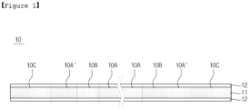
- FIG. 1 provides an exemplary structure of a negative electrode structure including a stack portion, a folding portion, and a wrapping portion.
- the stack portions (10A, 10A'), the folding portion (10B), and the wrapping portion (10C) are units that distinguish positions having different functions depending on the longitudinal direction of the negative electrode structure (10).
- the stack portions (10A, 10A'), the folding portion (10B), and the wrapping portion (10C) are not distinguished by a material other than a position.
- the stack portions (10A, 10A') refer to the negative electrode structure (10) at the position where the positive electrodes are stacked, and primarily have a straight shape in FIG. 2 .
- the folding portion (10B) refers to the negative electrode structure (10) in the position to connect the stack portions to each other, and has a predominantly curved shape in FIG. 2 .
- the folding portion (10B) may also be named a bending portion.
- the wrapping portion (10C) refers to a negative electrode structure in the position to wrap the stacked structure of the positive electrode and the negative electrode structure from the point where the top or bottom outermost stack portion (10A') ends, and has straight and curved shapes in FIG. 2 .
- the negative electrode structure (10) has wrapping portions (10C) at both ends relative to the longitudinal direction. That is, two wrapping portions (10C) are located at each of the longitudinal ends of the negative electrode structure (10). Furthermore, each of the wrapping portions (10C) contacts an outermost stack portion (10A'), and between the outermost stack portions (10A'), the folding portion (10B) and the stack portion (10A) are located alternately. Since the lengths of the stack portions (10A, 10A') are substantially equal to the length of the positive electrode, the length of each stack portion (10A, 10A') is substantially the same.
- the two wrapping portions (10C) located at both ends of the negative electrode structure (10) may have different lengths.
- the wrapping portion (10C) located at the point where the stacking begins is named the first wrapping portion
- the wrapping portion (10C) located at the point where the stacking ends is named the second wrapping portion.
- the wrapping portion (10C) located at the left end is the first wrapping portion
- the wrapping portion (10C) located at the right end is the second wrapping portion.
- the first wrapping portion and the second wrapping portion do not necessarily have the same length, as long as they can wrap around one side of the interior of the electrode assembly.
- the structural stability of the electrode assembly can be increased.
- the first wrapping portion and the second wrapping portion have the same length as each other.
- FIG. 2 provides an exemplary structure of an electrode assembly including a negative electrode structure and a positive electrode. Since the negative electrode structure (10) includes a negative electrode (11) and a separating film (12), the electrode assembly (1) includes a positive electrode (20), a negative electrode (11) and a separating film (12).
- the electrode assembly (1) has a plurality of stack portions (10A, 10A') sequentially positioned side by side in the thickness direction by the folding portion (10B), and at least one positive electrode is positioned between the stack portions (10A, 10A') adjacent to each other in the thickness direction.
- the electrode assembly (1) has a structure in which the exterior in the thickness direction and the longitudinal direction is surrounded by the first and second wrapping portions (10C) or the first and second wrapping portions and at least one outermost stack portion (10A').
- the interior of the electrode assembly (1) has a structure in which the stack portions (10A, 10A') of the negative electrode structure and the positive electrode (20) are stacked sequentially in an alternating manner.
- the exterior of the electrode assembly (1) is surrounded by at least one stack portion (10A') of the negative electrode structure and two wrapping portions (10C) of the negative electrode structure.
- the interior and exterior of the electrode assembly (1) are distinguished for the purpose of understanding the structure of the electrode assembly (1) according to the present invention, and in FIG. 2 , the layer exposed to the outside of the electrode assembly (1) in the thickness direction and the longitudinal direction indicates the exterior of the electrode assembly (1), and the inner portion of the exterior of the electrode assembly (1) indicates the interior of the electrode assembly (1).
- the stack portions (10A, 10A') are the negative electrode structure (10) at a position where the positive electrodes are stacked, and the wrapping portion (10C) starts from the point where the top or bottom outermost stack portion (10A') ends, when an end of the first wrapping portion (10C) is located on top of the outermost stack portion (10A'), as shown in FIG. 2 , a portion of the outermost stack portion (10A') may be located on the exterior of the electrode assembly (1), and a remaining portion of the outermost stack portion (10A') may be located on the interior of the electrode assembly (1).
- an outermost stack portion located inside or outside may refer to all or a portion of one stack portion.
- the exterior of the electrode assembly (1) may be formed with only a first or second wrapping portion (10C).
- the plurality of folding portions (10B) are wrapped by the wrapping portion (10C) so that they are not exposed to the outside in the thickness direction and the longitudinal direction.
- the electrode assembly (1) since the electrode assembly (1) according to one embodiment of the present invention has the stack portions (10A, 10A') of the negative electrode structure (10) and the positive electrode (20) stacked alternately and sequentially therein, the negative electrode structure (10) including the folding portion (10B) has a zigzag shape.
- the folding portion (10B) which are located sequentially from the stack portion (10A') in contact with the first or second wrapping portion of the negative electrode structure (10), is located alternately on the left or right side of the electrode assembly (1).
- the stack portions (10A, 10A') of the negative electrode structure (10) and the positive electrode (20) are not stacked alternately, and two or more of the stack portions or the positive electrodes are stacked successively, a potential difference may not occur between the successively stacked layers, and the efficiency of the battery may be reduced.
- the plurality of stack portions (10A, 10A') and the plurality of positive electrodes (20) become closer to each other in the thickness direction by the first and second wrapping portions (10C).
- the first and second wrapping portions (10C) can wrap the interior of the electrode assembly (1) with a higher tension compared to the stack portions (10A, 10A') or the folding portion (10B), which causes the internal constitutions of the electrode assembly (1) to be closer to each other in the thickness direction.
- the internal constitutions of the electrode assembly (1) become closer to each other in the thickness direction by this method, the internal constitutions of the electrode assembly (1) become inevitably closer to each other in the longitudinal direction.
- the first wrapping portion and the second wrapping portion do not contact each other, but are fixed on different outermost stack portions (10A') of the negative electrode structure.
- the first wrapping portion and the second wrapping portion do not overlap in forming the exterior of the final electrode assembly. If the first wrapping portion and the second wrapping portion overlap, an unnecessary negative electrode structure is used as much as the overlapping portion, which is undesirable in terms of material optimization.
- the end of the first wrapping portion and the end of the second wrapping portion may be located on top of the stack portion, and the stack portion on which the end of the first wrapping portion is located and the stack portion on which the end of the second wrapping portion is located may be different in order to form an efficient structure of the electrode assembly.
- one positive electrode is located between the stack portions (10A, 10A') which are adjacent to each other in the thickness direction, and the total number of positive electrodes (20) located between the stack portions (10A, 10A') is 2n (where n is a natural number). Since there is only one positive electrode (20) between the stack portions (10A, 10A') in the electrode assembly (1), the number of total positive electrodes herein refers to the total number of positive electrodes in the same situation, and does not mean that 2n positive electrodes are stacked between the stack portions. For example, in FIG. 2 , the total number of positive electrodes located between the stack portions is 4.
- all of the positive electrodes (20) are located between the stack portions.
- the upper limit of the number of total positive electrodes (20) is not particularly limited and may be adjusted within the conventional range in the art.
- the end of the first wrapping portion is opposite the end of the second wrapping portion.
- the end of the first wrapping portion is on the left side
- the end of the second wrapping portion is on the right side. In this case, even if the left and right sides inside the electrode assembly are wrapped with the first wrapping portion and the second wrapping portion, respectively, the first wrapping portion and the second wrapping portion may not overlap each other, and an electrode assembly with an efficient structure can be manufactured.
- the number of stack portions (10A, 10A') in the electrode assembly (1) may be one more than the number of positive electrodes (20). As described above, if 2n (wherein n is a natural number) total positive electrodes (20) are to be located between the stack portions, the number of stack portions (10A, 10A') is 2n+1 (wherein n is a natural number).
- the positive electrode (20) comprises a positive electrode active material layer (not shown in the drawing), and a current collector supporting the positive electrode active material (not shown in the drawing).
- the positive electrode (20) has a structure in which a positive electrode active material layer is formed on at least one side, more specifically on both sides, of the current collector.
- the positive electrode active material layer comprises a positive electrode active material and may further comprise a conductive material, a binder and an additive.
- the current collector, positive electrode active material, conductive material, binder or additive is not particularly limited as long as it is commonly used in the art.
- the positive electrode current collector supports the positive electrode active material layer and is not particularly limited to having a high conductivity without causing any chemical changes in the battery.
- the positive electrode current collector may be made of copper, stainless steel, aluminum, nickel, titanium, palladium, calcined carbon, copper or stainless steel whose surface is treated with carbon, nickel or silver, or aluminum-cadmium alloy.
- the positive electrode current collector can form microscopic irregularities on its surface to strengthen the binding with the positive electrode active material, and various forms can be used, such as films, sheets, foils, meshes, nets, porous materials, foams, non-woven materials, etc.
- a lithium-containing transition metal oxide may be used as the positive electrode active material.
- the positive electrode active material may comprise a sulfur compound.
- the sulfur compound may be at least one selected from the group consisting of elemental sulfur (S 8 ), organosulfur compound Li 2 S n (wherein n ⁇ 1), and carbon-sulfur polymer ((C 2 S x ) n , wherein x is 2.5 to 50, and n ⁇ 1).
- elemental sulfur S 8
- organosulfur compound Li 2 S n wherein n ⁇ 1
- carbon-sulfur polymer (C 2 S x ) n , wherein x is 2.5 to 50, and n ⁇ 1).
- inorganic sulfur (S 8 ) may be used.
- the electrode assembly (1) can be applied to a lithium-sulfur battery. Since the sulfur itself contained in the positive electrode active material is not electrically conductive, it may be used in combination with a conductive material such as a carbon material. Accordingly, the sulfur is included in the form of a sulfur-carbon composite, and preferably, the positive electrode active material may be a sulfur-carbon composite.
- the positive electrode (20) is relatively less easily folded and more easily cut compared to the negative electrode.
- the positive electrode (20) may be cut to a suitable size so that a plurality of positive electrodes are applied to the interior of the electrode assembly (1).
- the negative electrode (11) does not include a current collector supporting the lithium metal layer. Since the negative electrode (11) does not include a current collector, the loading amount of the negative electrode active material within the electrode assembly can be improved, which can contribute to improved performance of the battery.
- the negative electrode (11) is mainly composed of lithium metal, it may not be easy to process, such as cutting, because the lithium metal is highly ductile and viscous, but in the electrode assembly (1) according to one embodiment of the present invention, the processability can be improved by minimizing cutting while the negative electrode is applied in the form of the negative electrode structure (10).
- the lithium metal layer according to one embodiment of the present invention may be a free-standing lithium metal layer that can retain the shape to a certain level by itself.
- the separating film (12) covering both sides of the negative electrode (11) in the negative electrode structure (10) is not particularly limited in terms of type, provided that it does not include a binder on its surface.
- the separating film (12) may be a nonwoven or polyolefin-based porous material made of, for example, a glass fiber having a high melting point or a polyethylene terephthalate fiber, but is not limited thereto.
- the porous material is not particularly limited in the present invention, but any porous material conventionally used in electrochemical devices can be used.
- the porous material may include at least one selected from the group consisting of polyolefin such as polyethylene or polypropylene, polyester such as polyethyleneterephthalate or polybutyleneterephthalate, polyamide, polyacetal, polycarbonate, polyimide, polyetheretherketone, polyethersulfone, polyphenyleneoxide, polyphenylenesulfide, polyethylenenaphthalate, polytetrafluoroethylene, polyvinylidene fluoride, polyvinyl chloride, polyacrylonitrile, cellulose, nylon, poly(p-phenylene benzobisoxazole), and polyarylate.
- polyolefin such as polyethylene or polypropylene
- polyester such as polyethyleneterephthalate or polybutyleneterephthalate
- polyamide polyacetal
- polycarbonate polyimide
- polyetheretherketone polyethersulfone
- the lengths of the negative electrode (11) and the first and second separating films (12) in the negative electrode structure (10) are the same.
- the separating film located on the exterior of the electrode assembly (1) may be named the first separating film
- the separating film located on the interior of the electrode assembly (1) may be named the second separating film.
- the negative electrode (11) and the separating film (12) are provided to the electrode assembly (1) in the form of a negative electrode structure (10) having the negative electrode (11) interposed between the first and second separating films (12), wherein the negative electrode and the separating film are cut at one time, so that the lengths of the negative electrode (11) and the first and second separating films (12) in the negative electrode structure (10) are substantially the same, as shown in FIG. 1 .
- the ends of the first and second separating films (12) may be bent toward the center of the negative electrode structure (10).
- the first and second separating films are folded at the end of the negative electrode structure (10).
- the negative electrode structure (10) has substantially the same length of the negative electrode (11) and the first and second separating films (12) during the supplying process, when applied to the electrode assembly (1), the length of the lithium metal may be extended due to the ductility of the lithium metal during the folding process.
- the lithium metal protrudes longer than the first and second separating film.
- the separating film located more on the outer side than on the inner side of the folding portion (10B) may be shorter.
- the first separating film protrudes longer than the second separating film at the end of the negative electrode structure (10) on the side of the first or second wrapping portion (10C).
- the second separating film protrudes longer than the first separating film at the end of the negative electrode structure (10) on the side of the first or second wrapping portion (10C).
- the end of the first wrapping portion is located on a stack portion (10A') where the first wrapping portion turns to wrap around one side of an adjacent electrode assembly and abuts the second wrapping portion
- the end of the second wrapping portion is located on a stack portion where the second wrapping portion turns to wrap around one side of the adjacent electrode assembly and abuts the first wrapping portion.
- the stack portion refers to the outermost stack portion (10A').
- the ends of the first and second wrapping portions may be positioned in various ways on the outermost stack portion (10A').
- the first and second wrapping portions, respectively located on the stack portion do not overlap each other in the thickness direction.
- the ends of the first and second wrapping portions (10C) located on the outermost stack portion may be attached to the outermost stack portion (10A').
- the means and methods for the attachment are not particularly limited.
- the electrode assembly (1) further comprises a fixing member for securing the end of the first or second wrapping portion (10C) to the outermost stack portion (10A').
- FIG. 3 provides an exemplary structure of an electrode assembly in which the end of the wrapping portion is attached by a fixing member in the negative electrode structure.
- both ends of the negative electrode structure (10) can be fixed to form a stable structure.
- the tape (T) may be desirable to attach the tape (T) as a fixing member to wrap around the outer surface of the electrode assembly (1).
- the tape (T) has insulating properties and covers the entire end of the wrapping portion (10C) in the width direction, while taking into consideration the situation in which the lithium metal is extended and protruded due to the ductility of the lithium metal in the process of folding the negative electrode structure (10) when manufacturing the electrode assembly (1).
- the electrode assembly (1) is covered with a separating film or a tape from top to bottom and left to right.
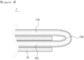
- FIG. 4 provides a zoomed-in drawing of a portion of the folding portion (10B) in the electrode assembly (1).
- the length of the folding portion (10B) in the negative electrode structure (10) is from 2 to 10 times the sum of the thicknesses of the positive electrode (20) and the negative electrode structure (10).
- the length of the folding portion (10B) means the length of the curve of the folding portion. In a curve, since the lengths of the inner and outer sides may be different from each other, the length of the center portion is measured. For example, the length can be measured by cutting the portion indicated by the dotted line in FIG. 4 and then unfolding it.
- the length of the folding portion (10B) may be 2 times or more, 2.5 times or more, 3 times or more, 3.5 times or more, 4 times or more, 10 times or less, 9.5 times or less, 9 times or less, 8.5 times or less, 8 times or less, 2 to 10 times, 3 to 9 times, or 4 to 8 times the sum of the thicknesses of the positive electrode (20) and the negative electrode structure (10).
- the length of the folding portion (10B) is adjusted within the range, the defect of the folding portion in the electrode assembly can be reduced, and the electrode assembly can be stably wrapped.
- the folding portion (10B) is subjected to a certain level of pressure in the inner direction of the electrode assembly (1). Accordingly, the folding portion (10B) can be appropriately disposed in the void between the portion on which the electrodes are stacked and the wrapping portion. Since the folding portion (10B) suitably disposed in the void includes the lithium metal layer (11) therein, it can contribute to further battery performance improvement by electrochemical reaction with the positive electrode (20) on the side thereof.
- the thickness of the lithium metal may be from 10 ⁇ m to 90 ⁇ m. Specifically, the thickness of the lithium metal may be 10 ⁇ m or more, 20 ⁇ m or more, or 30 ⁇ m or more, and may be 70 ⁇ m or less, 80 ⁇ m or less, or 90 ⁇ m or less.
- the thickness of the lithium metal is not necessarily limited thereto, and may be appropriately adjusted according to the actual size of the battery.
- the thickness of the positive electrode (20) may range from 100% greater than or less than 400%, specifically from 150% to 350%, and more specifically from 200% to 300%.
- the positive electrode satisfies the above-described thickness range, it can be suitably matched with the negative electrode structure.
- the extra negative electrode structure is present at both ends as first and second wrapping portions, and the first and second wrapping portions each wrap the side of an adjacent electrode laminate.
- wrapping the negative electrode structure so that the negative electrode structure is under a certain level of tension helps to compactly pack the folding portion within the void and helps the structure of the electrode laminate to maintain its shape without distortion.
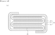
- the finished electrode assembly is in a state as shown in FIG. 6c or FIG. 6d .
- the wrapping has the effect of preventing the positive electrode from flowing down between the stack portions, and considering this function, it may be desirable to position the end of the negative electrode structure at the top of the electrode laminate.
- wrapping with tape (T) as shown in FIG. 6d may be an exemplary method.
- Example 1 Manufacture of an electrode assembly wrapped with a negative electrode structure
- the negative electrode structure was prepared by interposing 60 ⁇ m of lithium metal between two polyethylene (PE) separating films (11 ⁇ m).
- PE polyethylene
- a positive electrode compound composed of 85 wt% of positive electrode active material prepared by mixing sulfur and carbon nanotubes (CNTs) in a weight ratio of 7 : 3, 5 wt% of carbon nanofiber as a conductive material, and 10 wt% of binder was added to deionized water to prepare a positive electrode slurry, and then an aluminum collector was coated with the positive electrode slurry to produce a 200 ⁇ m positive electrode.
- the manufactured negative electrode structures were folded to make an electrode laminate in the manner shown in FIG. 6a , and then the electrode laminate was wrapped with extra negative electrode structures in the manner shown in FIG. 6b to make an electrode assembly as shown in FIG. 6c .
- the exposed end of the negative electrode structure in the electrode assembly was fixed with insulating tape as shown in FIG. 6d .
- the length of the folding portion was measured as 1,453 ⁇ m, and the vertical distance between the end of the positive electrode and the lateral wrapping portion was measured as 268 ⁇ m.
- Comparative Example 1 Manufacture of an electrode assembly in which the negative electrode structure is cut and laminated
- the negative electrode structure was cut to fit the positive electrode of each layer, and then the positive electrode and the negative electrode structure were laminated to form an electrode laminate, and the electrode assembly was completed without any separate wrapping with the negative electrode structure.
- the material and thickness of the positive electrode and the negative electrode structure were the same as in Example 1.
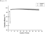
- Each electrode assembly prepared according to Example 1 and Comparative Example 1 was placed in the same pouch, and the ether-based electrolyte is charged with 0.4 M of LiFSI salt and 4 wt% of LiNO 3 to prepare a lithium secondary battery.
- the Coulombic efficiency of the prepared lithium secondary battery was measured by charging and discharging it at 0.3C, and the results are shown in FIG. 7 .
- the electrode assembly according to the present invention have advantages over conventional electrode assemblies in terms of process, but according to FIG. 7 , it can be seen that the long-term performance of the battery, such as Coulombic efficiency, can also be improved.
Landscapes
- Chemical & Material Sciences (AREA)
- Chemical Kinetics & Catalysis (AREA)
- Electrochemistry (AREA)
- General Chemical & Material Sciences (AREA)
- Engineering & Computer Science (AREA)
- Manufacturing & Machinery (AREA)
- Materials Engineering (AREA)
- Inorganic Chemistry (AREA)
- Secondary Cells (AREA)
- Cell Separators (AREA)
- Battery Electrode And Active Subsutance (AREA)
Applications Claiming Priority (4)
| Application Number | Priority Date | Filing Date | Title |
|---|---|---|---|
| KR20220136198 | 2022-10-21 | ||
| KR1020230070472A KR20240056395A (ko) | 2022-10-21 | 2023-05-31 | 전극 조립체 및 이를 포함하는 전기화학소자 |
| KR1020230139636A KR102837705B1 (ko) | 2022-10-21 | 2023-10-18 | 전극 조립체 및 이를 포함하는 전기화학소자 |
| PCT/KR2023/016371 WO2024085720A1 (ko) | 2022-10-21 | 2023-10-20 | 전극 조립체 및 이를 포함하는 전기화학소자 |
Publications (2)
| Publication Number | Publication Date |
|---|---|
| EP4517907A1 true EP4517907A1 (de) | 2025-03-05 |
| EP4517907A4 EP4517907A4 (de) | 2025-08-27 |
Family
ID=90738151
Family Applications (1)
| Application Number | Title | Priority Date | Filing Date |
|---|---|---|---|
| EP23880295.3A Pending EP4517907A4 (de) | 2022-10-21 | 2023-10-20 | Elektrodenanordnung und elektrochemische vorrichtung damit |
Country Status (5)
| Country | Link |
|---|---|
| US (1) | US20250391922A1 (de) |
| EP (1) | EP4517907A4 (de) |
| JP (1) | JP2025521667A (de) |
| CN (1) | CN119487668A (de) |
| WO (1) | WO2024085720A1 (de) |
Family Cites Families (12)
| Publication number | Priority date | Publication date | Assignee | Title |
|---|---|---|---|---|
| GB0016057D0 (en) * | 2000-06-30 | 2000-08-23 | Aea Technology Plc | A method of assembling a cell |
| KR101278739B1 (ko) * | 2008-11-07 | 2013-06-25 | 주식회사 엘지화학 | 중첩 전기화학소자 |
| JP5259453B2 (ja) * | 2009-02-25 | 2013-08-07 | 富士重工業株式会社 | 蓄電デバイスおよびその製造方法 |
| KR101553542B1 (ko) * | 2012-09-14 | 2015-09-16 | 에스케이이노베이션 주식회사 | 2차 전지 내부 셀 스택 방법 및 이를 이용하여 제조되는 셀 스택 |
| KR101775565B1 (ko) * | 2015-02-13 | 2017-09-19 | 주식회사 엘지화학 | 하나의 음극 시트를 포함하고 있는 전극조립체 |
| KR102023530B1 (ko) | 2015-08-12 | 2019-09-24 | 주식회사 엘지화학 | 전극 조립체 |
| KR20200095896A (ko) * | 2019-02-01 | 2020-08-11 | 주식회사 엘지화학 | 전극 조립체 제조방법과, 이를 통해 제조된 전극 및 이차전지 |
| CN111244528A (zh) * | 2020-01-16 | 2020-06-05 | 中航锂电技术研究院有限公司 | 锂硫电池电芯、锂硫电池及其制备方法 |
| KR102828353B1 (ko) * | 2020-03-04 | 2025-07-03 | 주식회사 엘지에너지솔루션 | 전극 조립체 및 그의 제조 방법 |
| WO2022066584A1 (en) | 2020-09-22 | 2022-03-31 | Tesla, Inc. | Sintered cathode active material elements and methods thereof |
| US11933933B2 (en) | 2021-03-31 | 2024-03-19 | Asahi Kasei Microdevices Corporation | Event detection method, event detection system, and non-transitory computer-readable recording medium |
| KR20230139636A (ko) | 2022-03-28 | 2023-10-05 | 지디앤와이 주식회사 | 정전기 분무를 이용한 버섯 스낵 제조 방법 및 제조 장치 |
-
2023
- 2023-10-20 WO PCT/KR2023/016371 patent/WO2024085720A1/ko not_active Ceased
- 2023-10-20 JP JP2024576533A patent/JP2025521667A/ja active Pending
- 2023-10-20 EP EP23880295.3A patent/EP4517907A4/de active Pending
- 2023-10-20 CN CN202380051243.5A patent/CN119487668A/zh active Pending
- 2023-10-20 US US18/881,245 patent/US20250391922A1/en active Pending
Also Published As
| Publication number | Publication date |
|---|---|
| EP4517907A4 (de) | 2025-08-27 |
| CN119487668A (zh) | 2025-02-18 |
| WO2024085720A1 (ko) | 2024-04-25 |
| JP2025521667A (ja) | 2025-07-10 |
| US20250391922A1 (en) | 2025-12-25 |
Similar Documents
| Publication | Publication Date | Title |
|---|---|---|
| US6709785B2 (en) | Stacked electrochemical cell and method for preparing the same | |
| US6726733B2 (en) | Multiply stacked electrochemical cell and method for preparing the same | |
| EP4027422A1 (de) | Sekundärbatterie und vorrichtung damit | |
| JP6898850B2 (ja) | 積層/折畳み型電極組立体 | |
| KR102837703B1 (ko) | 전극 조립체 및 이를 포함하는 전기화학소자 | |
| KR20240056395A (ko) | 전극 조립체 및 이를 포함하는 전기화학소자 | |
| EP4517907A1 (de) | Elektrodenanordnung und elektrochemische vorrichtung damit | |
| EP4496063A1 (de) | Elektrodenanordnung und elektrochemische vorrichtung damit | |
| EP4517908A1 (de) | Elektrodenanordnung und elektrochemische vorrichtung damit | |
| KR102837705B1 (ko) | 전극 조립체 및 이를 포함하는 전기화학소자 | |
| KR102837704B1 (ko) | 전극 조립체 및 이를 포함하는 전기화학소자 | |
| EP4485607A1 (de) | Elektrodenanordnung und elektrochemisches element damit | |
| EP4557439A1 (de) | Elektrodenanordnung und elektrochemische vorrichtung damit | |
| KR102876045B1 (ko) | 전극 조립체 및 이를 포함하는 전기화학소자 | |
| US20250219125A1 (en) | Method of manufacturing electrode assembly | |
| KR102848105B1 (ko) | 전극 조립체의 제조 방법 | |
| KR102886515B1 (ko) | 전극 조립체, 이의 제조방법 및 이를 포함하는 전기화학소자 | |
| US20250273725A1 (en) | Mandrel unit, jellyroll forming method, electrode assembly, and secondary battery | |
| US20260011894A1 (en) | Electrode, electrode assembly and method of manufacturing electrode assembly | |
| US20260058219A1 (en) | Electrode assembly and secondary battery including the same | |
| CN118891766A (zh) | 电极组件和包括该电极组件的电化学元件 |
Legal Events
| Date | Code | Title | Description |
|---|---|---|---|
| STAA | Information on the status of an ep patent application or granted ep patent |
Free format text: STATUS: THE INTERNATIONAL PUBLICATION HAS BEEN MADE |
|
| PUAI | Public reference made under article 153(3) epc to a published international application that has entered the european phase |
Free format text: ORIGINAL CODE: 0009012 |
|
| STAA | Information on the status of an ep patent application or granted ep patent |
Free format text: STATUS: REQUEST FOR EXAMINATION WAS MADE |
|
| 17P | Request for examination filed |
Effective date: 20241129 |
|
| AK | Designated contracting states |
Kind code of ref document: A1 Designated state(s): AL AT BE BG CH CY CZ DE DK EE ES FI FR GB GR HR HU IE IS IT LI LT LU LV MC ME MK MT NL NO PL PT RO RS SE SI SK SM TR |
|
| A4 | Supplementary search report drawn up and despatched |
Effective date: 20250729 |
|
| RIC1 | Information provided on ipc code assigned before grant |
Ipc: H01M 10/0583 20100101AFI20250723BHEP Ipc: H01M 4/134 20100101ALI20250723BHEP Ipc: H01M 10/052 20100101ALI20250723BHEP |
|
| DAV | Request for validation of the european patent (deleted) | ||
| DAX | Request for extension of the european patent (deleted) | ||
| STAA | Information on the status of an ep patent application or granted ep patent |
Free format text: STATUS: EXAMINATION IS IN PROGRESS |