EP4517879A1 - Lithium-nickel-manganoxid-positivelektrodenmaterial, herstellungsverfahren dafür und anwendung davon - Google Patents
Lithium-nickel-manganoxid-positivelektrodenmaterial, herstellungsverfahren dafür und anwendung davon Download PDFInfo
- Publication number
- EP4517879A1 EP4517879A1 EP23802448.3A EP23802448A EP4517879A1 EP 4517879 A1 EP4517879 A1 EP 4517879A1 EP 23802448 A EP23802448 A EP 23802448A EP 4517879 A1 EP4517879 A1 EP 4517879A1
- Authority
- EP
- European Patent Office
- Prior art keywords
- positive electrode
- electrode material
- lithium nickel
- nickel manganate
- manganate positive
- Prior art date
- Legal status (The legal status is an assumption and is not a legal conclusion. Google has not performed a legal analysis and makes no representation as to the accuracy of the status listed.)
- Pending
Links
Images


Classifications
-
- C—CHEMISTRY; METALLURGY
- C01—INORGANIC CHEMISTRY
- C01G—COMPOUNDS CONTAINING METALS NOT COVERED BY SUBCLASSES C01D OR C01F
- C01G53/00—Compounds of nickel
- C01G53/40—Complex oxides containing nickel and at least one other metal element
- C01G53/42—Complex oxides containing nickel and at least one other metal element containing alkali metals, e.g. LiNiO2
- C01G53/44—Complex oxides containing nickel and at least one other metal element containing alkali metals, e.g. LiNiO2 containing manganese
- C01G53/54—Complex oxides containing nickel and at least one other metal element containing alkali metals, e.g. LiNiO2 containing manganese of the type (Mn2O4)-, e.g. Li(NixMn2-x)O4 or Li(MyNixMn2-x-y)O4
-
- C—CHEMISTRY; METALLURGY
- C01—INORGANIC CHEMISTRY
- C01G—COMPOUNDS CONTAINING METALS NOT COVERED BY SUBCLASSES C01D OR C01F
- C01G53/00—Compounds of nickel
- C01G53/40—Complex oxides containing nickel and at least one other metal element
- C01G53/42—Complex oxides containing nickel and at least one other metal element containing alkali metals, e.g. LiNiO2
- C01G53/44—Complex oxides containing nickel and at least one other metal element containing alkali metals, e.g. LiNiO2 containing manganese
- C01G53/52—Complex oxides containing nickel and at least one other metal element containing alkali metals, e.g. LiNiO2 containing manganese of the type (Mn2O4)2-, e.g. Li2(NixMn2-x)O4 or Li2(MyNixMn2-x-y)O4
-
- H—ELECTRICITY
- H01—ELECTRIC ELEMENTS
- H01M—PROCESSES OR MEANS, e.g. BATTERIES, FOR THE DIRECT CONVERSION OF CHEMICAL ENERGY INTO ELECTRICAL ENERGY
- H01M10/00—Secondary cells; Manufacture thereof
- H01M10/05—Accumulators with non-aqueous electrolyte
- H01M10/052—Li-accumulators
-
- H—ELECTRICITY
- H01—ELECTRIC ELEMENTS
- H01M—PROCESSES OR MEANS, e.g. BATTERIES, FOR THE DIRECT CONVERSION OF CHEMICAL ENERGY INTO ELECTRICAL ENERGY
- H01M10/00—Secondary cells; Manufacture thereof
- H01M10/05—Accumulators with non-aqueous electrolyte
- H01M10/052—Li-accumulators
- H01M10/0525—Rocking-chair batteries, i.e. batteries with lithium insertion or intercalation in both electrodes; Lithium-ion batteries
-
- H—ELECTRICITY
- H01—ELECTRIC ELEMENTS
- H01M—PROCESSES OR MEANS, e.g. BATTERIES, FOR THE DIRECT CONVERSION OF CHEMICAL ENERGY INTO ELECTRICAL ENERGY
- H01M4/00—Electrodes
- H01M4/02—Electrodes composed of, or comprising, active material
- H01M4/36—Selection of substances as active materials, active masses, active liquids
- H01M4/362—Composites
- H01M4/366—Composites as layered products
-
- H—ELECTRICITY
- H01—ELECTRIC ELEMENTS
- H01M—PROCESSES OR MEANS, e.g. BATTERIES, FOR THE DIRECT CONVERSION OF CHEMICAL ENERGY INTO ELECTRICAL ENERGY
- H01M4/00—Electrodes
- H01M4/02—Electrodes composed of, or comprising, active material
- H01M4/36—Selection of substances as active materials, active masses, active liquids
- H01M4/48—Selection of substances as active materials, active masses, active liquids of inorganic oxides or hydroxides
- H01M4/50—Selection of substances as active materials, active masses, active liquids of inorganic oxides or hydroxides of manganese
- H01M4/505—Selection of substances as active materials, active masses, active liquids of inorganic oxides or hydroxides of manganese of mixed oxides or hydroxides containing manganese for inserting or intercalating light metals, e.g. LiMn2O4 or LiMn2OxFy
-
- H—ELECTRICITY
- H01—ELECTRIC ELEMENTS
- H01M—PROCESSES OR MEANS, e.g. BATTERIES, FOR THE DIRECT CONVERSION OF CHEMICAL ENERGY INTO ELECTRICAL ENERGY
- H01M4/00—Electrodes
- H01M4/02—Electrodes composed of, or comprising, active material
- H01M4/36—Selection of substances as active materials, active masses, active liquids
- H01M4/48—Selection of substances as active materials, active masses, active liquids of inorganic oxides or hydroxides
- H01M4/52—Selection of substances as active materials, active masses, active liquids of inorganic oxides or hydroxides of nickel, cobalt or iron
- H01M4/525—Selection of substances as active materials, active masses, active liquids of inorganic oxides or hydroxides of nickel, cobalt or iron of mixed oxides or hydroxides containing iron, cobalt or nickel for inserting or intercalating light metals, e.g. LiNiO2, LiCoO2 or LiCoOxFy
-
- H—ELECTRICITY
- H01—ELECTRIC ELEMENTS
- H01M—PROCESSES OR MEANS, e.g. BATTERIES, FOR THE DIRECT CONVERSION OF CHEMICAL ENERGY INTO ELECTRICAL ENERGY
- H01M4/00—Electrodes
- H01M4/02—Electrodes composed of, or comprising, active material
- H01M4/36—Selection of substances as active materials, active masses, active liquids
- H01M4/58—Selection of substances as active materials, active masses, active liquids of inorganic compounds other than oxides or hydroxides, e.g. sulfides, selenides, tellurides, halogenides or LiCoFy; of polyanionic structures, e.g. phosphates, silicates or borates
- H01M4/5825—Oxygenated metallic salts or polyanionic structures, e.g. borates, phosphates, silicates, olivines
-
- H—ELECTRICITY
- H01—ELECTRIC ELEMENTS
- H01M—PROCESSES OR MEANS, e.g. BATTERIES, FOR THE DIRECT CONVERSION OF CHEMICAL ENERGY INTO ELECTRICAL ENERGY
- H01M4/00—Electrodes
- H01M4/02—Electrodes composed of, or comprising, active material
- H01M4/62—Selection of inactive substances as ingredients for active masses, e.g. binders, fillers
-
- C—CHEMISTRY; METALLURGY
- C01—INORGANIC CHEMISTRY
- C01P—INDEXING SCHEME RELATING TO STRUCTURAL AND PHYSICAL ASPECTS OF SOLID INORGANIC COMPOUNDS
- C01P2002/00—Crystal-structural characteristics
- C01P2002/50—Solid solutions
- C01P2002/52—Solid solutions containing elements as dopants
-
- C—CHEMISTRY; METALLURGY
- C01—INORGANIC CHEMISTRY
- C01P—INDEXING SCHEME RELATING TO STRUCTURAL AND PHYSICAL ASPECTS OF SOLID INORGANIC COMPOUNDS
- C01P2002/00—Crystal-structural characteristics
- C01P2002/50—Solid solutions
- C01P2002/52—Solid solutions containing elements as dopants
- C01P2002/54—Solid solutions containing elements as dopants one element only
-
- C—CHEMISTRY; METALLURGY
- C01—INORGANIC CHEMISTRY
- C01P—INDEXING SCHEME RELATING TO STRUCTURAL AND PHYSICAL ASPECTS OF SOLID INORGANIC COMPOUNDS
- C01P2002/00—Crystal-structural characteristics
- C01P2002/80—Crystal-structural characteristics defined by measured data other than those specified in group C01P2002/70
- C01P2002/85—Crystal-structural characteristics defined by measured data other than those specified in group C01P2002/70 by XPS, EDX or EDAX data
-
- C—CHEMISTRY; METALLURGY
- C01—INORGANIC CHEMISTRY
- C01P—INDEXING SCHEME RELATING TO STRUCTURAL AND PHYSICAL ASPECTS OF SOLID INORGANIC COMPOUNDS
- C01P2002/00—Crystal-structural characteristics
- C01P2002/80—Crystal-structural characteristics defined by measured data other than those specified in group C01P2002/70
- C01P2002/88—Crystal-structural characteristics defined by measured data other than those specified in group C01P2002/70 by thermal analysis data, e.g. TGA, DTA, DSC
-
- C—CHEMISTRY; METALLURGY
- C01—INORGANIC CHEMISTRY
- C01P—INDEXING SCHEME RELATING TO STRUCTURAL AND PHYSICAL ASPECTS OF SOLID INORGANIC COMPOUNDS
- C01P2004/00—Particle morphology
- C01P2004/01—Particle morphology depicted by an image
- C01P2004/03—Particle morphology depicted by an image obtained by SEM
-
- C—CHEMISTRY; METALLURGY
- C01—INORGANIC CHEMISTRY
- C01P—INDEXING SCHEME RELATING TO STRUCTURAL AND PHYSICAL ASPECTS OF SOLID INORGANIC COMPOUNDS
- C01P2004/00—Particle morphology
- C01P2004/51—Particles with a specific particle size distribution
-
- C—CHEMISTRY; METALLURGY
- C01—INORGANIC CHEMISTRY
- C01P—INDEXING SCHEME RELATING TO STRUCTURAL AND PHYSICAL ASPECTS OF SOLID INORGANIC COMPOUNDS
- C01P2004/00—Particle morphology
- C01P2004/60—Particles characterised by their size
- C01P2004/61—Micrometer sized, i.e. from 1-100 micrometer
-
- C—CHEMISTRY; METALLURGY
- C01—INORGANIC CHEMISTRY
- C01P—INDEXING SCHEME RELATING TO STRUCTURAL AND PHYSICAL ASPECTS OF SOLID INORGANIC COMPOUNDS
- C01P2004/00—Particle morphology
- C01P2004/80—Particles consisting of a mixture of two or more inorganic phases
-
- C—CHEMISTRY; METALLURGY
- C01—INORGANIC CHEMISTRY
- C01P—INDEXING SCHEME RELATING TO STRUCTURAL AND PHYSICAL ASPECTS OF SOLID INORGANIC COMPOUNDS
- C01P2006/00—Physical properties of inorganic compounds
- C01P2006/11—Powder tap density
-
- C—CHEMISTRY; METALLURGY
- C01—INORGANIC CHEMISTRY
- C01P—INDEXING SCHEME RELATING TO STRUCTURAL AND PHYSICAL ASPECTS OF SOLID INORGANIC COMPOUNDS
- C01P2006/00—Physical properties of inorganic compounds
- C01P2006/12—Surface area
-
- C—CHEMISTRY; METALLURGY
- C01—INORGANIC CHEMISTRY
- C01P—INDEXING SCHEME RELATING TO STRUCTURAL AND PHYSICAL ASPECTS OF SOLID INORGANIC COMPOUNDS
- C01P2006/00—Physical properties of inorganic compounds
- C01P2006/12—Surface area
- C01P2006/13—Surface area thermal stability thereof at high temperatures
-
- C—CHEMISTRY; METALLURGY
- C01—INORGANIC CHEMISTRY
- C01P—INDEXING SCHEME RELATING TO STRUCTURAL AND PHYSICAL ASPECTS OF SOLID INORGANIC COMPOUNDS
- C01P2006/00—Physical properties of inorganic compounds
- C01P2006/40—Electric properties
-
- C—CHEMISTRY; METALLURGY
- C01—INORGANIC CHEMISTRY
- C01P—INDEXING SCHEME RELATING TO STRUCTURAL AND PHYSICAL ASPECTS OF SOLID INORGANIC COMPOUNDS
- C01P2006/00—Physical properties of inorganic compounds
- C01P2006/80—Compositional purity
-
- H—ELECTRICITY
- H01—ELECTRIC ELEMENTS
- H01M—PROCESSES OR MEANS, e.g. BATTERIES, FOR THE DIRECT CONVERSION OF CHEMICAL ENERGY INTO ELECTRICAL ENERGY
- H01M4/00—Electrodes
- H01M4/02—Electrodes composed of, or comprising, active material
- H01M2004/021—Physical characteristics, e.g. porosity, surface area
-
- H—ELECTRICITY
- H01—ELECTRIC ELEMENTS
- H01M—PROCESSES OR MEANS, e.g. BATTERIES, FOR THE DIRECT CONVERSION OF CHEMICAL ENERGY INTO ELECTRICAL ENERGY
- H01M4/00—Electrodes
- H01M4/02—Electrodes composed of, or comprising, active material
- H01M2004/026—Electrodes composed of, or comprising, active material characterised by the polarity
- H01M2004/028—Positive electrodes
-
- H—ELECTRICITY
- H01—ELECTRIC ELEMENTS
- H01M—PROCESSES OR MEANS, e.g. BATTERIES, FOR THE DIRECT CONVERSION OF CHEMICAL ENERGY INTO ELECTRICAL ENERGY
- H01M2220/00—Batteries for particular applications
- H01M2220/20—Batteries in motive systems, e.g. vehicle, ship, plane
-
- Y—GENERAL TAGGING OF NEW TECHNOLOGICAL DEVELOPMENTS; GENERAL TAGGING OF CROSS-SECTIONAL TECHNOLOGIES SPANNING OVER SEVERAL SECTIONS OF THE IPC; TECHNICAL SUBJECTS COVERED BY FORMER USPC CROSS-REFERENCE ART COLLECTIONS [XRACs] AND DIGESTS
- Y02—TECHNOLOGIES OR APPLICATIONS FOR MITIGATION OR ADAPTATION AGAINST CLIMATE CHANGE
- Y02E—REDUCTION OF GREENHOUSE GAS [GHG] EMISSIONS, RELATED TO ENERGY GENERATION, TRANSMISSION OR DISTRIBUTION
- Y02E60/00—Enabling technologies; Technologies with a potential or indirect contribution to GHG emissions mitigation
- Y02E60/10—Energy storage using batteries
Definitions
- the present application belongs to the technical field of positive electrode materials of lithium batteries, and specifically relates to a lithium nickel manganate positive electrode material and a preparation method therefor and an application thereof.
- High-voltage nickel manganese positive electrode material LiNi 0.5 Mn 1.5 O 4 contains no cobalt element, which is cost-effective and environmentally friendly, being considered to be an extremely promising next-generation positive electrode material of lithium battery.
- olivine-like lithium iron phosphate (LiFePO 4 , abbreviated as LFP) spinel-type high-voltage nickel manganese having three-dimensional lithium ion channels has a better rate and low-temperature performance; and has a single-battery energy density of 235-250Wh/kg, which is increased by 30-40% compared with LFP, but Wh (Watt-hour) cost thereof is close to or slightly lower than that of LFP.
- the average working voltage of high-voltage nickel manganese is >4.7V (vs. Li+). Since the working voltage is relatively high, there is currently no commercially available 5V window electrolyte, resulting in that the electrolyte is susceptible to be decomposed in the use of high-voltage nickel manganese in a full cell and thus Mn element is precipitated, thereby leading to swelling and cycle fading of the full cell. This limits commercial application thereof.
- a single-crystallized high-voltage nickel manganese material may be prepared; the high-voltage lithium nickel manganate material having good dispersity of single crystals has excellent electrochemical performance due to advantages of small specific surface area, few interface side reactions, few gas generation, and less stress cracks, good mechanical properties, and controllable crystal face exposure; (2) the high-voltage nickel manganese material may be coated to inhibit the precipitation of Mn and isolate the contact between the positive electrode material and the electrolyte so as to alleviate the decomposition of the electrolyte, this further solve the problems of gas generation and capacity fade of the high-voltage nickel manganese in a full cell.
- Patent CN 109461925 A introduces the addition of a small amount of doping elements having fluxing property such as Na, Si, Ba, Sr, F, Cl, etc. as well as lattice-strengthening elements such as Al, Mg, La, Ce, etc.
- the high-voltage nickel manganese material is in a spinel-type structure, which is essentially different from the structure of nickel-cobalt-manganese ternary layered structure materials. Dispersing elements of ternary materials cannot be directly used as dispersing elements for single crystals of the high-voltage nickel manganese material.
- a special precursor having a large specific surface area (30m 2 /g), being loosened, and having a low tap density (0.8g/cm 3 ) is prepared, a slurry of the precursor is viscous and is prone to blocking a thickener when the thickener is used. Therefore, the process is difficult to be amplified, and thus the subsequent mass production process is directly impacted. Therefore, in order to meet the need of subsequent production amplification, commonly used precursors with moderate specific surface area (20m 2/ g) and moderate tap density (1.2g/cm 3 ) are prepared in the current precursor process.
- the surface of a lithium nickel manganate material is uniformly coated with a layer of oxide or phosphate, solid electrolyte and other fast ion conductors to mainly achieve performance improvement.
- the uniform and high coating method may isolate the direct contact between the positive electrode material and the electrolyte, inhibiting the decomposition of the electrolyte.
- Phosphate has better thermodynamic stability and ionic conductivity, and is capable of generating lithium phosphate, manganese phosphate and other substances on the surface of the positive electrode material. Such substances are relatively stable at high voltage and may be effectively used as a coating layer for high-voltage positive electrode material.
- Patent CN 105261740 A discloses a method for preparing a surface coating of a lithium nickel manganate positive electrode material.
- the main idea of this method is weighing a phosphate salt and a lithium salt, adding a complexing agent to obtain a lithium phosphate sol, and mixing the sol with lithium nickel manganate and drying, and then performing mixed sintering. This improves the cycle stability and rate performance of the spinel-type lithium nickel manganate.
- the sol-gel method the cost is high, sample recovery is difficult, the coating layer is too thick, and it is difficult to repeat the experiment, and thus the method is not suitable for mass production.
- Patent CN10602525 B proposes coating lithium titanium phosphate (LiTi(PO 4 ) 3 ) onto the surface of a positive electrode material through a two-step wet chemical method, followed by performing heat treatment to form a fast-ion-conductor-type solid electrolyte layer so as to improve the rate performance of the material.
- This method has cumbersome processes and is costly, and n-butyl titanate used in the processes has low toxicity. These are not conducive to large-scale commercial production.
- Patent CN104766960 B proposes adding lithium nickel manganate into water, then adding a surfactant to the suspension, then adding sodium meta-aluminate solution, stirring and introducing carbon dioxide to the mixed solution to adjust the pH value, and then performing heat treatment in a muffle furnace to obtain an alumina-coated lithium nickel manganate positive electrode material.
- a gas is used in this method to adjust pH, and thus it is difficult to control experimental processes. Therefore, this is not conducive to large-scale production.
- a first aspect of the present application provides a lithium nickel manganate positive electrode material, having a molecular formula of Li ⁇ Ni ⁇ Mn 2- ⁇ M ⁇ O 4- ⁇ /N, where 0.95 ⁇ 1.1, 0.4 ⁇ 0.6, 0.0005 ⁇ 0.02, 0 ⁇ 0.2, M is a single-crystal dispersing element, and M is at least one of V, Nb, Ta, Mo or W; N represents a coating layer, and the coating layer includes a P compound and/or an Al compound; a coating amount of N is 500-10000ppm.
- a mass ratio of Al to P is (0.2-3):1.
- a coating rate S1/(S1+S2) of P and/or Al is 20%-80%; where S1 is a peak area corresponding to a content m 1 of P and/or Al, and S2 is a peak area corresponding to a content m 2 of Ni and Mn elements.
- the lithium nickel manganate positive electrode material when the coating layer is the P compound, the lithium nickel manganate positive electrode material has a BET of 0.4-0.7m 2 /g.
- the lithium nickel manganate positive electrode material when the coating layer is the Al compound, the lithium nickel manganate positive electrode material has a BET of 0.6-0.9m 2 /g.
- the lithium nickel manganate positive electrode material has a BET of 0.6-0.9m 2 /g.
- the lithium nickel manganate positive electrode material provided by the present application is in a spinel-type crystal structure and belongs to Fd3m or P4 3 32 space point groups.
- Single crystal has a relative large grain size, has a D50 of 4-10 ⁇ m, and has a morphology of octahedron or truncated octahedron, and the cross section thereof is dense with no hollows or faults. Residual lithium on its surface is low, (carbonate radical + hydroxide radical) ⁇ 500ppm.
- the material has a good thermal stability and a high thermal decomposition temperature, with a DSC decomposition temperature of 275-295°C.
- the powder compaction density of the material is 2.8-3.2g/cm 3 at 3.5T.
- a second aspect of the present application provides a preparation method of a lithium nickel manganate positive electrode material, including the following steps:
- the Al source has a particle size of 30-60nm.
- the Al source includes at least one of Al 2 O 3 , AlPO 4 , or Al(OH) 3 .
- the coating agent is the Al source, it may be obtained directly, since the industrialization of nanometer-sized coating agents of this type of compounds is relatively mature.
- an Al-containing substance does not melt, but due to that the coating agent is nanometer-sized (30-60nm), it may also be more uniformly attached to the surface of the positive electrode material, and the coating rate is higher after the sintering reaction.
- the coating amount of Al in the lithium nickel manganate is 500-10000ppm, and the coating rate of Al is 20%-80%.
- the BET of this material will significantly increase due to the influence of the nanometer-sized coating agent, and the BET is 0.6-0.9m 2 /g after coating.
- the P source when the coating agent contains the P source, has a particle size of 3-5 ⁇ m.
- the P source includes at least one of Li 3 PO 4 , AlPO 4 , LiFePO 4 , FePO 4 , NH 4 H 2 PO 4 or (NH 4 ) 2 HPO 4 .
- the coating agent is the P source, after being subjected to refinement treatment, it is refined from 2-3mm to 3-5 ⁇ m, since this type of compound has a lower melting point.
- a P-containing substance melts and more uniformly attached to the surface of the positive electrode material, and thus the coating rate is higher after the sintering reaction.
- the coating rate of P may reach up to 80%, where the coating rate of P is tested through XPS, and XPS may be used to test the content and state of the surface of the positive electrode material.
- peak areas (S) correspond to different elements on the surface of the positive electrode material is directly proportional to the element content (m)
- the content m1 of P corresponds to the peak area S1
- the content m2 of Ni and Mn elements corresponds to the peak area S2
- the coating rate of P is S1/(S1+S2).
- the coating amount of P in the lithium nickel manganate is 500-10000ppm, where the coating amount of P is tested and the proportion of the content of P element in the positive electrode material is tested by ICP.
- the BET of the positive electrode material will slightly increase due to the influence of the coating agent.
- the BET is 0.4-0.7m 2 /g after coating.
- the precursor has a molecular formula of Ni ⁇ Mn 2- ⁇ (OH) 4 , where 0.4 ⁇ 0.6; the precursor has at least one of the following properties that the precursor has a D50 of 2-8 ⁇ m; the precursor has a specific surface area of 10-30m 2 /g; and the precursor has a tap density of 0.8-1.5g/cm 3 .
- the D50 of the precursor is 3-5 ⁇ m
- the specific surface area of the precursor is 15-25m 2 /g
- the tap density of the precursor is 1.0-1.3g/cm 3 .
- the lithium source is at least one of lithium carbonate, lithium hydroxide, lithium oxalate, lithium nitrate, lithium chloride, lithium fluoride or lithium acetate.
- the single-crystal dispersant includes at least one of V 2 O 5 , NH 4 VO 3 , Nb 2 O 5 , LiNbO 3 , Ta 2 O 5 , LiTaO 3 , H 2 MoO 4 , (NH 4 ) 2 MoO 4 , H 2 WO 4 or WO 3 .
- a molar ratio of the precursor to the lithium source is 1:(0.5-1.1); and an added amount of the single-crystal dispersant is 0.1%-1% of a mass of the precursor.
- the speed for mixing and stirring is 600-1000rpm, and the stirring time under this condition is 15-60min.
- the mixture in S1 and the secondary mixture in S3 are placed in an atmosphere box type furnace for sintering, and an oxygen concentration of the atmosphere in the atmosphere box type furnace is 15%-40%.
- the first sintering is: heating from room temperature up to 800-1000°C at a rate of 1-5°C/min, calcining for 6-15h, and then cooling down to 600-800°C at a rate of 0. 1-2°C/min, keeping the temperature for 1-10h, and finally, naturally cooling down to the room temperature.
- the high single-crystal dispersion material has a BET of 0.3-0.5m 2 /g.
- the second sintering is: heating from room temperature up to 300-600°C at a heating rate of 1-5°C/min, calcining for 6-15h, and then naturally cooling down to the room temperature.
- a third aspect of the present application provides a lithium battery having the above-mentioned lithium nickel manganate positive electrode material; or having the above-mentioned lithium nickel manganate positive electrode material prepared by the above method.
- a fourth aspect of the present application provides an electrical device having the above-mentioned lithium battery.
- a fifth aspect of the present application provides an electric vehicle having the above-mentioned lithium battery.
- the present application provides a lithium nickel manganate positive electrode material, having a single-crystal dispersing element and a coating layer of P compound and/or Al compound. Due to that the material has smaller BET, extremely low residual lithium on its surface, and the coating of P and/or Al, there are fewer side reactions at the material interface and cycle performance is better. Due to the appropriate particle size control on the material, the material has both a good capacity rate performance and cycling performance. Due to the material has a higher DSC decomposition temperature, the material has excellent thermal stability.
- the present application provides a preparation method of a lithium nickel manganate positive electrode material. Firstly, by means of adding a small amount of a single-crystal dispersing element (V, Nb, Ta, Mo or W), a high-voltage nickel manganese material having good dispersity of single crystals is prepared, therefore, this material has smaller specific surface area.
- a single-crystal dispersing element V, Nb, Ta, Mo or W
- the single-crystal dispersant containing a single-crystal dispersing element (containing a compound of V/Nb/Ta/Mo/W) has better solubility for the lithium source and precursor, the lithium source and precursor, after being melted at high temperature, have a low viscosity under the action of the single-crystal dispersant. Therefore, the lithium source and precursor have a fast mass transfer rate, have higher mobility ratio than that in a solid phase, and are diffused together after a short time to react, and thus they have smaller interface energy and thermal stress so as to be easily saturated to form a single crystal material having a specific special crystal plane orientation. Hence, the addition of a single-crystal dispersing element can make the lithium nickel manganate positive electrode material has better dispersity of single crystals and smaller specific surface area.
- the positive electrode material is prevented from directly contacting the electrolyte to cause oxidative decomposition. Therefore, the positive electrode material can be isolated from HF or can be prevented from reacting with HF. This inhibits HF to corrode the positive electrode and improves the stability of the material, and thus improves the cycle performance of battery. Under an appropriate temperature, the P source melts, and uniformly coats onto the surface of the material after liquefaction of the P source. Finally, a lithium nickel manganate material having high coating rate is obtained to achieve the purpose of uniform coating.
- phosphates formed have thermodynamic stability, and good stability to HF and high voltage. Moreover, the formed phosphates (lithium phosphate, manganese phosphate, nickel phosphate) have higher ionic conductivity, and all batteries prepared have smaller impedance growth and better cycle performance.
- an inert layer or a fast ion conductor such as LiAlO 2 may be formed, which can isolate HF or the reaction with HF. This inhibits HF to corrode the positive electrode, improves the stability of the material, and promotes the transmission of Li + , thereby improving the capacity and cycle performance of battery.
- the present application adopts dry coating, which is convenient, fast, cost-effective and suitable for industrial production.
- an Al source that is in nanometer size or a P source that has been subjected to refining treatment is adopted.
- the size of coating particles and the size of the positive electrode material are quite different, and the coating agent may be uniformly coated on the surface of the high-voltage nickel manganese material. Since nanometer-sized P source is difficult to obtain directly, the P source used in the present application has been refined, and additionally the P source is easy to be melted, a good effect of uniform coating can also be obtained.
- the coating method which results in a uniform and dense coating and a high coating rate, the positive electrode material is prevented from directly contacting the electrolyte to cause oxidative decomposition, thereby effectively reducing the gas generation of battery and greatly improving the cycle performance of battery.
- the coating rate of conventional dry coating methods is ⁇ 50%.
- the maximum coating rate after nanometer-sized or refined Al and/or P is used for coating may be increased to 70%-80%.
- a lithium nickel manganate material is described in the present application, having a molecular formula: Li ⁇ Ni ⁇ Mn 2- ⁇ M ⁇ O 4- ⁇ /N, where 0.95 ⁇ 1.1, 0.4 ⁇ 0.6, 0.0005 ⁇ 0.02, 0 ⁇ 0.2; M is a single-crystal dispersing element, and M is at least one of V, Nb, Ta, Mo or W; N represents a coating layer, and the coating layer includes a P compound and/or an Al compound; the coating amount of N is 500-10000ppm.
- a mass ratio of Al to P is (0.2-3):1, and may be selected from 0.2:1, 0.33:1, 0.5:1, 1:1, 2:1 or 3:1.
- the covering rate may be selected from 20%, 30%, 40%, 50%, 60%, 70% or 80%.
- the lithium nickel manganate positive electrode material has a BET of 0.4-0.7m 2 /g.
- the lithium nickel manganate positive electrode material has a BET of 0.6-0.9m 2 /g.
- the lithium nickel manganate positive electrode material has a BET of 0.6-0.9m 2 /g.
- lithium nickel manganate positive electrode material residual lithium on a surface of the lithium nickel manganate positive electrode material is ⁇ 500ppm.
- a DSC decomposition temperature of the lithium nickel manganate positive electrode material is 275-295°C.
- a powder compaction density of the lithium nickel manganate positive electrode material is 2.8-3.2g/cm 3 at 3.5T.
- D50 of the lithium nickel manganate positive electrode material is 4-10 ⁇ m.
- the present application further provides a preparation method for the above-mentioned lithium nickel manganate positive electrode material to explain the preparation process of the above-mentioned lithium nickel manganate positive electrode material, however the preparation of the above-mentioned lithium nickel manganate positive electrode material is not limited to this method.
- the preparation method used as an example includes but is not limited to the following steps.
- S1 a precursor, a lithium source, and a single-crystal dispersant are mixed and stirred evenly.
- the ⁇ may be 0.4, 0.5 or 0.6.
- the specific surface area of the precursor is 10m 2 /g, 18m 2 /g, 24m 2 /g or 30m 2 /g.
- the tap density of the precursor is 0.8g/cm 3 , 1g/cm 3 , 1.2g/cm 3 , 1.3g/cm 3 or 1.5g/cm 3 .
- the lithium source is at least one of lithium carbonate, lithium hydroxide, lithium oxalate, lithium nitrate, lithium chloride, lithium fluoride or lithium acetate.
- the single-crystal dispersant includes at least one of V 2 O 5 , NH 4 VO 3 , Nb 2 O 5 , LiNbO 3 , Ta 2 O 5 , LiTaO 3 , H 2 MoO 4 , (NH 4 ) 2 MoO 4 , H 2 WO 4 or WO 3 .
- a molar ratio of the precursor to the lithium source is 1:0.5-1.1, and the added amount of the single-crystal dispersant is 0.1%-1% of the mass of the precursor.
- the molar ratio of the precursor to lithium carbonate is 1:0.5, 1:0.51, 1:0.52, 1:0.54 or 1:0.55; when the lithium source is lithium hydroxide, lithium oxalate, lithium nitrate, lithium chloride, lithium fluoride or lithium acetate, the molar ratio of the precursor to the lithium source is 1:1, 1:1.02, 1:1.04, 1:1.08 or 1:1.1; and the added amount of the single-crystal dispersant is 0.1%, 0.3%, 0.5%, 0.8% or 1.0% of the mass of the precursor.
- an oxygen concentration of the atmospheric environment is 15%-40%.
- the oxygen concentration of the atmospheric environment is 15%, 18%, 20%, 25%, 30%, 35% or 40%.
- the first sintering is: heating from room temperature up to 800-1000°C at a rate of 1-5°C/min, calcining for 6-15h, and then cooling down to 600-800°C at a rate of 0.1-2°C/min, keeping the temperature for 1-10h, and finally, naturally cooling down to room temperature.
- the following are performed: heating up to 800°C at a rate of 2°C/min, calcining for 6 hours, then cooling down to 600°C at a rate of 0.1°C/min, keeping the temperature for 1h, and finally, naturally cooling down to room temperature.
- the following are performed: heating up to 900°C at a rate of 3°C/min, calcining for 10 hours, then cooling down to 700°C at a rate of 0.5°C/min, keeping the temperature for 5h, and finally, naturally cooling down to room temperature.
- the following are performed: heating up to 1000°C at a rate of 5°C/min, calcining for 15 hours, then cooling down to 800°C at a rate of 2°C/min, keeping the temperature for 10h, and finally, naturally cooling down to room temperature.
- the BET of the high single-crystal dispersion material is 0.3-0.5m 2 /g.
- S3 the high single-crystal dispersion material and a coating agent are mixed and evenly stirred to obtain a secondary mixture.
- the particle size of the Al source is 30-60nm.
- the Al source includes at least one of Al 2 O 3 , AlPO 4 , or Al(OH) 3 .
- the particle size of the P source is 3-5 ⁇ m.
- the P source includes at least one of Li 3 PO 4 , AlPO 4 , LiFePO 4 , FePO 4 , NH 4 H 2 PO 4 or (NH 4 ) 2 HPO 4 .
- the coating agent is a P source and/or an Al source.
- the second sintering is: heating from room temperature up to 300-600°C at a heating rate of 1-5°C/min, calcining for 6-15h, and then naturally cooling down to room temperature.
- the following are performed: heating from room temperature up to 300°C at a heating rate of 1°C/min, calcining for 6h, and then naturally cooling down to room temperature.
- the following are performed: heating from room temperature up to 400°C at a heating rate of 2°C/min, calcining for 8h, and then naturally cooling down to room temperature.
- the following are performed: heating from room temperature up to 500°C at a heating rate of 4°C/min, calcining for 10h, and then naturally cooling down to room temperature.
- the following are performed: heating from room temperature up to 600°C at a heating rate of 5°C/min, calcining for 15h, and then naturally cooling down to room temperature.
- the lithium nickel manganate positive electrode material of the present application may be applied to a lithium-ion battery.
- the lithium-ion battery may be used in an electrical device, and the electrical device may specifically be a 3C electronic product, a power tool, etc.
- the lithium-ion battery may also be used in an electric vehicle.
- the lithium-ion battery may also be used in the field of energy storage.
- the positive electrode active material, conductive carbon Super P, KS6 and polyvinylidene fluoride (HSV900) were mixed according to a mass ratio of 94.5%: 2%: 1%: 2.5% to form an uniform slurry, and then the slurry was uniformly coated on an aluminum foil and dried, with a surface density controlled at 16mg/cm 2 on a single side. Then the latter was rolled by using a roller machine to obtain a positive electrode sheet having a compaction density of 3.0g/cm 3 , and then the positive electrode sheet was put into a vacuum drying box and dried at 120°C for 10h. The positive electrode sheet, a separator, and a negative electrode sheet were wound into a battery cell.
- HSV900 polyvinylidene fluoride
- the battery cell was designed to have a nominal capacity of 600mAh, a NP ratio of 1.12, an injected liquid of 3g, the separator was a PP/PE composite separator, the negative electrode was graphite, and the electrolyte was a high-voltage electrolyte (Xinzhoubang LBC502A50).
- the full cell was placed for 1 day for formation, with a voltage range of 3.4-4.85V. It was charged with 0.05C constant current for 1h, with 0.1C constant current for 1h, and with 0.2C constant current for 1h to 4.85V. It was charged at a constant voltage of 4.85V until the current is less than 0.05C, discharged at 0.33C to 3.4V, so as to obtain an initial capacity for 0.33C.
- An initial capacity for 0.33C was tested to be 129.5mAh/g, a capacity retention rate after 500 cycles was tested to be 67.5%, and a gas generated was tested to be 5.6mL/Ah.
- Example 2 The difference between Example 2 and Example 1 was that the single-crystal dispersant used in Example 2 was Nb 2 O 5 .
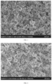
- the BET of the sample after the first sintering was 0.36m 2 /g; as can be seen from the SEM scanning image shown in FIG. 2 , the effect of single crystal dispersion was good when Nb 2 O 5 was used as a single-crystal dispersant.
- the coated lithium nickel manganate positive electrode material LiNi 0.5 Mn 1.5 Nb 0.0041 O 4 /P was obtained, with the BET of the coated sample being 0.45m 2 /g.
- the coated lithium nickel manganate positive electrode material was subjected to an ICP test, and the coating amount of P was 1500ppm.
- the full cell preparation was the same as that of Example 1.
- the initial capacity for 0.33C was tested to be 131.2mAh/g, the capacity retention rate after 500 cycles was tested to be 72.9%, and a gas generated was 5.8mL/Ah.
- Example 3 The difference between Example 3 and Example 1 was that the single-crystal dispersant used in Example 3 was Ta 2 O 5 .
- the BET of the sample after the first sintering was 0.47m 2 /g; as can be seen from the SEM scanning image shown in FIG. 3 , the effect of single crystal dispersion was good when Ta 2 O 5 was used as a single-crystal dispersant.
- the coated lithium nickel manganate positive electrode material LiNi 0.5 Mn 1.5 Ta 0.0024 O 4 /P was obtained, with the BET of the coated sample being 0.56m 2 /g.
- the coated lithium nickel manganate positive electrode material was subjected to an ICP test, and the coating amount of P was 1500ppm.
- the full cell preparation was the same as that of Example 1.
- the initial capacity for 0.33C was tested to be 132.1mAh/g, the capacity retention rate after 500 cycles was tested to be 78.5%, and a gas generated was 4.8mL/Ah.
- Example 4 The difference between Example 4 and Example 1 was that the single-crystal dispersant used in Example 4 was H 2 MoO 4 .
- the BET of the sample after the first sintering was 0.48m 2 /g; as can be seen from the SEM scanning image shown in FIG. 4 , the effect of single crystal dispersion was good when H 2 MoO 4 was used as a single-crystal dispersant.
- the coated lithium nickel manganate positive electrode material LiNi 0.5 Mn 1.5 Mo 0.0033 O 4 /P was obtained, with the BET of the coated sample being 0.59m 2 /g.
- the coated lithium nickel manganate positive electrode material was subjected to an ICP test, and the coating amount of P was 1500ppm.
- the full cell preparation was the same as that of Example 1.
- the initial capacity for 0.33C was tested to be 128.6mAh/g, the capacity retention rate after 500 cycles was tested to be 68.2%, and a gas generated was 6.7mL/Ah.
- Example 5 The difference between Example 5 and Example 1 was that the single-crystal dispersant used in Example 5 was WO 3 .
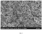
- the BET of the sample after the first sintering was 0.35m 2 /g; as can be seen from the SEM scanning image shown in FIG. 5 , the effect of single crystal dispersion was good when WO 3 was used as a single-crystal dispersant.
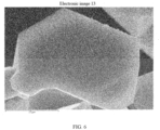
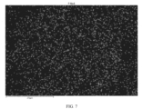
- the coated lithium nickel manganate positive electrode material LiNi 0.5 Mn 1.5 W 0.0023 O 4 /P was obtained, with the BET of the coated sample being 0.49m 2 /g, the residual lithium on the surface being 105ppm, the DSC decomposition temperature being 291°C, and the powder compaction density at 3.5T being 3.10g/cm 3 .
- the SEM scanning image and the EDS Mapping of P were shown in FIG. 6 and FIG. 7 , it can be seen that the P coating was uniform without agglomeration.
- the coated lithium nickel manganate positive electrode material was subjected to an ICP test, and the coating amount of P was 1500ppm.
- the full cell preparation was the same as that of Example 1.
- the initial capacity for 0.33C was tested to be 129.9mAh/g, the capacity retention rate after 500 cycles was tested to be 70.5%, and a gas generated was 6.1mL/Ah.
- the full cell preparation was the same as that of Example 1.
- the initial capacity for 0.33C was tested to be 128.4mAh/g, the capacity retention rate after 500 cycles was tested to be 65.5 %, and a gas generated was 5.9mL/Ah.
- Example 7 The difference between Example 7 and Example 6 was that the single-crystal dispersant used in Example 7 was Nb 2 O 5 .
- the BET of the sample after the first sintering was 0.36m 2 /g; the SEM scanning image was shown in FIG. 2 .
- the coated lithium nickel manganate positive electrode material LiNi 0.5 Mn 1.5 Nb 0.0041 O 4 /Al was obtained, with the BET of the coated sample being 0.78m 2 /g.
- the coated lithium nickel manganate positive electrode material was subjected to an ICP test, and the coating amount of Al was 1500ppm.
- the full cell preparation was the same as that of Example 1.
- the initial capacity for 0.33C was tested to be 130.2mAh/g, the capacity retention rate after 500 cycles was tested to be 69.8%, and a gas generated was 5.7mL/Ah.
- Example 8 The difference between Example 8 and Example 6 was that the single-crystal dispersant used in Example 8 was Ta 2 O 5 .
- the BET of the sample after the first sintering was 0.47m 2 /g; the SEM scanning image was shown in FIG. 3 .
- the coated lithium nickel manganate positive electrode material LiNi 0.5 Mn 1.5 Ta 0.0024 O 4 /Al was obtained, with the BET of the coated sample being 0.86m 2 /g.
- the coated lithium nickel manganate positive electrode material was subjected to an ICP test, and the coating amount of Al was 1500ppm.
- the full cell preparation was the same as that of Example 1.
- the initial capacity for 0.33C was tested to be 131.5mAh/g, the capacity retention rate after 500 cycles was tested to be 74.2%, and a gas generated was 5mL/Ah.
- Example 9 The difference between Example 9 and Example 6 was that the single-crystal dispersant used in Example 9 was H 2 MoO 4 .
- the BET of the sample after the first sintering was 0.48m 2 /g; the SEM scanning image was shown in FIG. 4 .
- the coated lithium nickel manganate positive electrode material LiNi 0.5 Mn 1.5 Mo 0.0033 O 4 /Al was obtained, with the BET of the coated sample being 0.82m 2 /g.
- the coated lithium nickel manganate positive electrode material was subjected to an ICP test, and the coating amount of Al was 1500ppm.
- the full cell preparation was the same as that of Example 1.
- the initial capacity for 0.33C was tested to be 129.3mAh/g, the capacity retention rate after 500 cycles was tested to be 70.5%, and a gas generated was 5.8mL/Ah.
- Example 10 The difference between Example 10 and Example 6 was that the single-crystal dispersant used in Example 10 was WO 3 .
- the BET of the sample after the first sintering was 0.35m 2 /g; the SEM scanning image was shown in FIG. 5 .
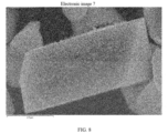
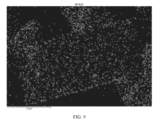
- the coated lithium nickel manganate positive electrode material LiNi 0.5 Mn 1.5 W 0.0023 O 4 /Al was obtained, with the BET of the coated sample being 0.81m 2 /g, the residual lithium on the surface being 237ppm, the DSC decomposition temperature being 287°C, and the powder compaction density at 3.5T being 3.04g/cm 3 .
- the SEM scanning image and the EDS Mapping of Al were shown in FIG. 8 and FIG. 9 respectively, it can be seen that the Al coating was uniform without agglomeration.
- the coated lithium nickel manganate positive electrode material was subjected to an ICP test, and the coating amount of Al was 1500ppm.
- the full cell preparation was the same as that of Example 1.
- the initial capacity for 0.33C was tested to be 129.5mAh/g, the capacity retention rate after 500 cycles was tested to be 68.4 %, and a gas generated was 5.2mL/Ah.
- the full cell preparation was the same as that of Example 1.
- the initial capacity at 0.33C was tested to be 129.2mAh/g, the capacity retention rate after 500 cycles was tested to be 39.6%, and a gas generated was 9.4mL/Ah.
- Comparative example 2 The difference between Comparative example 2 and Example 1 was that in Comparative example 2, no single-crystal dispersant and coating agent were used, and the second sintering was not conducted.
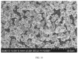
- the lithium nickel manganate positive electrode material LiNi 0.5 Mn 1.5 O 4 was obtained, the BET of the sample after the first sintering was 0.67m 2 /g, and as can be seen from the SEM scanning image shown in FIG. 10 , the effect of single crystal dispersion was not good with partial agglomeration.
- the full cell preparation was the same as that of Example 1.
- the initial capacity for 0.33C was tested to be 130.9mAh/g, the capacity retention rate after 500 cycles was tested to be 35.4%, and a gas generated was 12.1mL/Ah.
- Comparative example 3 The difference between Comparative example 3 and Example 5 was that the coating agent used in Comparative example 3 was ZnO, with an amount of 1500ppm.
- the coated lithium nickel manganate positive electrode material was subjected to an ICP test, and the coating amount of Zn was 1500ppm.
- the full cell preparation was the same as that of Example 1.
- the initial capacity for 0.33C was tested to be 129.4mAh/g, the capacity retention rate after 500 cycles was tested to be 45.1%, and a gas generated was 9.2mL/Ah.
- Comparative example 4 The difference between Comparative example 4 and Example 5 was that the coating agent used in Comparative example 4 was Cr 2 O 3 .
- the coated lithium nickel manganate positive electrode material LiNi 0.5 Mn 1.5 W 0.0023 O 4 /Cr.
- the coated lithium nickel manganate positive electrode material was subjected to an ICP test, and the coating amount of Cr was 1500ppm.
- the full cell preparation was the same as that of Example 1.
- the initial capacity for 0.33C was tested to be 129.8mAh/g, the capacity retention rate after 500 cycles was tested to be 49.8%, and a gas generated was 8.7mL/Ah.
- the full cell preparation was the same as that of Example 1.
- the initial capacity for 0.33C was tested to be 130.1mAh/g, the capacity retention rate after 500 cycles was tested to be 66.4%, and a gas generated was 5.7mL/Ah.
- Example 12 The difference between Example 12 and Example 11 was that the single-crystal dispersant used in Example 12 was Nb 2 O 5 .
- the BET of the sample after the first sintering was 0.36m 2 /g; the SEM scanning image was shown in FIG. 2 .
- the coated lithium nickel manganate positive electrode material LiNi 0.5 Mn 1.5 Nb 0.0041 O 4 /P-Al was obtained, with the BET of the coated sample being 0.69m 2 /g.
- the coated lithium nickel manganate positive electrode material was subjected to an ICP test, and the coating amounts of P and Al were 750ppm and 750ppm respectively.
- the full cell preparation was the same as that of Example 1.
- the initial capacity for 0.33C was tested to be 130.5mAh/g, the capacity retention rate after 500 cycles was tested to be 70.1%, and a gas generated was 5.8mL/Ah.
- Example 13 The difference between Example 13 and Example 11 was that the single-crystal dispersant used in Example 12 was Ta 2 O 5 .
- the BET of the sample after the first sintering was 0.47m 2 /g; the SEM scanning image was shown in FIG. 3 .
- the coated lithium nickel manganate positive electrode material LiNi 0.5 Mn 1.5 Ta 0.0024 O 4 /P-Al was obtained, with the BET of the coated sample being 0.71m 2 /g.
- the coated lithium nickel manganate positive electrode material was subjected to an ICP test, and the coating amounts of P and Al were 750ppm and 750ppm respectively.
- the full cell preparation was the same as that of Example 1.
- the initial capacity for 0.33C was tested to be 131.2mAh/g, the capacity retention rate after 500 cycles was tested to be 72.3%, and a gas generated was 5.4mL/Ah.
- Example 14 The difference between Example 14 and Example 11 was that the single-crystal dispersant used in Example 14 was H 2 MoO 4 .
- the BET of the sample after the first sintering was 0.48m 2 /g; the SEM scanning image was shown in FIG. 4 .
- the coated lithium nickel manganate positive electrode material LiNi 0.5 Mn 1.5 Mo 0.0033 O 4 /Al was obtained, with the BET of the coated sample being 0.74m 2 /g.
- the coated lithium nickel manganate positive electrode material was subjected to an ICP test, and the coating amounts of P and Al were 750ppm and 750ppm respectively.
- the full cell preparation was the same as that of Example 1.
- the initial capacity for 0.33C was tested to be 130.4mAh/g, the capacity retention rate after 500 cycles was tested to be 65.9%, and a gas generated was 6.2mL/Ah.
- Example 15 The difference between Example 15 and Example 11 was that the single-crystal dispersant used in Example 11 was WO 3 .
- the BET of the sample after the first sintering was 0.35m 2 /g; the SEM scanning image was shown in FIG. 5 .
- the coated lithium nickel manganate positive electrode material LiNi 0.5 Mn 1.5 W 0.0023 O 4 /P-Al was obtained, with the BET of the coated sample being 0.64m 2 /g, the residual lithium on the surface being 246ppm, the DSC decomposition temperature being 288°C, and the powder compaction density at 3.5T being 3.03g/cm 3 .
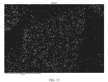
- the SEM scanning image and the EDS Mapping of P and Al were shown in FIG. 11 , FIG. 12 and FIG.
- Example 1 Electrochemical properties for Examples 1 to 15 and Comparative examples 1 to 4 Serial number Single crystal dispersant BET after the first sintering (m 2 /g) Coating agent Coating amount (ppm) Capacity for 0.33C (mAh/g) Capacity retention rate after 500 cycles (%) Gas generation (mL/Ah)
- Example 1 V 2 O 5 0.37 NH 4 H 2 PO 4 1500 129.5 67.5 5.6
- Comparative example 1 even if the single-crystal dispersing element was added to obtain the positive electrode material having good single crystal dispersion, its electrochemical performance was not as good as that of the coated positive electrode materials in Examples 1 to 15, and its performance in terms of cycling and gas generation was significantly worse, since it was not subjected to coating.
- Example 16 The difference between Example 16 and Example 5 was that the coating agent used in Example 16 was (NH 4 ) 2 HPO 4 .
- the BET of the sample after the first sintering was 0.35m 2 /g; the SEM scanning image was shown in FIG. 5 .
- the coated lithium nickel manganate positive electrode material LiNi 0.5 Mn 1.5 W 0.0023 O 4 /P was obtained.
- the coated lithium nickel manganate positive electrode material was subjected to an ICP test, and the coating amount of P was 1500ppm.
- the full cell preparation was the same as that of Example 1.
- the initial capacity for 0.33C was tested to be 130.2mAh/g, the capacity retention rate after 500 cycles was tested to be 68.7%, and a gas generated was 5.9mL/Ah.
- Example 17 The difference between Example 17 and Example 5 was that the coating agent used in Example 17 was Li 3 PO 4 .
- the BET of the sample after the first sintering was 0.35m 2 /g; the SEM scanning image was shown in FIG. 5 .
- the coated lithium nickel manganate positive electrode material LiNi 0.5 Mn 1.5 W 0.0023 O 4 /P was obtained.
- the coated lithium nickel manganate positive electrode material was subjected to an ICP test, and the coating amount of P was 1500ppm.
- the full cell preparation was the same as that of Example 1.
- the initial capacity for 0.33C was tested to be 130.8mAh/g, the capacity retention rate after 500 cycles was tested to be 72.4%, and a gas generated was 5.6mL/Ah.
- Example 18 The difference between Example 18 and Example 5 was that the coating agent used in Example 18 was FePO 4 .
- the BET of the sample after the first sintering was 0.35m 2 /g; the SEM scanning image was shown in FIG. 5 .
- the coated lithium nickel manganate positive electrode material LiNi 0.5 Mn 1.5 W 0.0023 O 4 /P was obtained.
- the coated lithium nickel manganate positive electrode material was subjected to an ICP test, and the coating amount of P was 1500ppm.
- the full cell preparation was the same as that of Example 1.
- the initial capacity for 0.33C was tested to be 131.5mAh/g, the capacity retention rate after 500 cycles was tested to be 73.5%, and a gas generated was 5.7mL/Ah.
- Example 19 The difference between Example 19 and Example 5 was that the coating agent used in Example 19 was LiFePO 4 .
- the BET of the sample after the first sintering was 0.35m 2 /g; the SEM scanning image was shown in FIG. 5 .
- the coated lithium nickel manganate positive electrode material LiNi 0.5 Mn 1.5 W 0.0023 O 4 /P was obtained.
- the coated lithium nickel manganate positive electrode material was subjected to an ICP test, and the coating amount of P was 1500ppm.
- the full cell preparation was the same as that of Example 1.
- the initial capacity for 0.33C was tested to be 130.7mAh/g, the capacity retention rate after 500 cycles was tested to be 69.3%, and a gas generated was 6.1mL/Ah.
- Example 20 The difference between Example 20 and Example 10 was that the coating agent used in Example 20 was Al(OH) 3 .
- the BET of the sample after the first sintering was 0.35m 2 /g; the SEM scanning image was shown in FIG. 5 .
- the coated lithium nickel manganate positive electrode material LiNi 0.5 Mn 1.5 W 0.0023 O 4 /Al was obtained.
- the coated lithium nickel manganate positive electrode material was subjected to an ICP test, and the coating amount of Al was 1500ppm.
- the full cell preparation was the same as that of Example 1.
- the initial capacity for 0.33C was tested to be 129.5mAh/g, the capacity retention rate after 500 cycles was tested to be 67.4%, and a gas generated was 6.5mL/Ah.
- Example 21 The difference between Example 21 and Example 10 was that the coating agent used in Example 21 was LiAlO 2 .
- the BET of the sample after the first sintering was 0.35m 2 /g; the SEM scanning image was shown in FIG. 5 .
- the coated lithium nickel manganate positive electrode material LiNi 0.5 Mn 1.5 W 0.0023 O 4 /Al was obtained.
- the coated lithium nickel manganate positive electrode material was subjected to an ICP test, and the coating amount of Al was 1500ppm.
- the full cell preparation was the same as that of Example 1.
- the initial capacity for 0.33C was tested to be 130.3mAh/g, the capacity retention rate after 500 cycles was tested to be 71.6%, and a gas generated was 5.4mL/Ah.
- Example 22 The difference between Example 22 and Example 15 was that the coating agent used in Example 22 was AlPO 4 .
- the BET of the sample after the first sintering was 0.35m 2 /g; the SEM scanning image was shown in FIG. 5 .
- the coated lithium nickel manganate positive electrode material LiNi 0.5 Mn 1.5 W 0.002 O 4 /P-Al was obtained.
- the coated lithium nickel manganate positive electrode material was subjected to an ICP test, and the coating amounts of P and Al were 760ppm and 660ppm respectively.
- the full cell preparation was the same as that of Example 1.
- the initial capacity for 0.33C was tested to be 131.2mAh/g, the capacity retention rate after 500 cycles was tested to be 72.6%, and a gas generated was 5.2mL/Ah.
- Example 23 The difference between Example 23 and Example 15 was that the coating agents used in Example 23 were (NH 4 ) 2 HPO 4 and Al 2 O 3 .
- the BET of the sample after the first sintering was 0.35m 2 /g; the SEM scanning image was shown in FIG. 5 .
- the coated lithium nickel manganate positive electrode material LiNi 0.5 Mn 1.5 W 0.002 O 4 /P-Al was obtained.
- the coated lithium nickel manganate positive electrode material was subjected to an ICP test, and the coating amounts of P and Al were 750ppm and 750ppm respectively.
- the full cell preparation was the same as that of Example 1.
- the initial capacity for 0.33C was tested to be 129.8mAh/g, the capacity retention rate after 500 cycles was tested to be 70.5%, and a gas generated was 6.1mL/Ah.
- Example 24 The difference between Example 24 and Example 15 was that the coating agents used in Example 24 were FePO 4 and Al 2 O 3 .
- the BET of the sample after the first sintering was 0.35m 2 /g; the SEM scanning image was shown in FIG. 5 .
- the coated lithium nickel manganate positive electrode material LiNi 0.5 Mn 1.5 W 0.0023 O 4 /P-Al was obtained.
- the coated lithium nickel manganate positive electrode material was subjected to an ICP test, and the coating amounts of P and Al were 750ppm and 750ppm respectively.
- the full cell preparation was the same as that of Example 1.
- the initial capacity for 0.33C was tested to be 130.1mAh/g, the capacity retention rate after 500 cycles was tested to be 72.4%, and a gas generated was 6mL/Ah.
- Example 25 The difference between Example 25 and Example 15 was that the coating agents used in Example 25 were (NH 4 ) 2 HPO 4 and Al(OH) 3 .
- the BET of the sample after the first sintering was 0.35m 2 /g; the SEM scanning image was shown in FIG. 5 .
- the coated lithium nickel manganate positive electrode material LiNi 0.5 Mn 1.5 W 0.002 O 4 /P-Al was obtained.
- the coated lithium nickel manganate positive electrode material was subjected to an ICP test, and the coating amounts of P and Al were 750ppm and 750ppm respectively.
- Example 16 Electrochemical performance for Examples 16 to 25 Serial number Single crystal dispersant BET after the first sintering (m 2 /g) Coating agent Coating amount (ppm) Capacity for 0.33C (mAh/g) Capacity retention rate after 500 cycles (%) Gas generation (mL/Ah)
- Example 16 WO 3 0.35 (NH 4 ) 2 HPO 4 1500 130.2 68.7 5.9
- Example 17 WO 3 0.35 Li 3 PO 4 1500 130.8 72.4 5.6
- Example 18 WO 3 0.35 FePO 4 1500 131.5 73.5 5.7
- Example 19 WO 3 0.35 LiFePO 4 1500 130.7 69.3 6.1
- Example 20 WO 3 0.35 Al(OH) 3 1500 129.5 67.4 6.5
- Example 21 WO 3 0.35 LiAlO 2 1500 130.3 71.6 5.4
- P and Al sources resultes in different electrochemical performance effects, they are overall significantly better than the situation of no coating or coating with other substances.
- preferred P sources mainly are (NH 4 ) 2 HPO 4 , NH 4 H 2 PO 4 and FePO 4
- Al sources mainly are Al 2 O 3 and Al(OH) 3
- AlPO 4 is mainly used for co-coating.
- Comparative example 5 The difference between Comparative example 5 and Example 5 was that the coating amount of P in Comparative example 5 was 200ppm.
- the BET of the sample after the first sintering was 0.35m 2 /g; the SEM scanning image was shown in FIG. 5 .
- the coated lithium nickel manganate positive electrode material LiNi 0.5 Mn 1.5 W 0.0023 O 4 /P was obtained.
- the coated lithium nickel manganate positive electrode material was subjected to an ICP test, and the coating amount of P was 200ppm, and the coating rate of P was 12%.
- the full cell preparation was the same as that of Example 1.
- the initial capacity for 0.33C was tested to be 130.1mAh/g, the capacity retention rate after 500 cycles was tested to be 59.7%, and a gas generated was 7.5mL/Ah.
- the full cell preparation was the same as that of Example 1.
- the initial capacity for 0.33C was tested to be 132.5mAh/g, the capacity retention rate after 500 cycles was tested to be 69.3%, and a gas generated was 6.5mL/Ah.
- Example 27 The difference between Example 27 and Example 5 was that the coating amount of P in Example 27 was 1000ppm.
- the BET of the sample after the first sintering was 0.35m 2 /g; the SEM scanning image was shown in FIG. 5 .
- the coated lithium nickel manganate positive electrode material LiNi 0.5 Mn 1.5 W 0.0023 O 4 /P was obtained.
- the coated lithium nickel manganate positive electrode material was subjected to an ICP test, and the coating amount of P was 1000ppm, and the coating rate of P was 57%.
- the full cell preparation was the same as that of Example 1.
- the initial capacity for 0.33C was tested to be 131.4mAh/g, the capacity retention rate after 500 cycles was tested to be 72.5%, and a gas generated was 5.2mL/Ah.
- Example 28 The difference between Example 28 and Example 5 was that the coating amount of P in Example 28 was 2000ppm.
- the BET of the sample after the first sintering was 0.35m 2 /g; the SEM scanning image was shown in FIG. 5 .
- the coated lithium nickel manganate positive electrode material LiNi 0.5 Mn 1.5 W 0.0023 O 4 /P was obtained.
- the coated lithium nickel manganate positive electrode material was subjected to an ICP test, and the coating amount of P was 2000ppm, and the coating rate of P was 62%.
- the full cell preparation was the same as that of Example 1.
- the initial capacity for 0.33C was tested to be 132.2mAh/g, the capacity retention rate after 500 cycles was tested to be 70.3%, and a gas generated was 6.7mL/Ah.
- Example 29 The difference between Example 29 and Example 5 was that the coating amount of P in Example 29 was 3000ppm.
- the BET of the sample after the first sintering was 0.35m 2 /g; the SEM scanning image was shown in FIG. 5 .
- the coated lithium nickel manganate positive electrode material LiNi 0.5 Mn 1.5 W 0.0023 O 4 /P was obtained.
- the coated lithium nickel manganate positive electrode material was subjected to an ICP test, and the coating amount of P was 3000ppm, and the coating rate of P was 69%.
- the full cell preparation was the same as that of Example 1.
- the initial capacity for 0.33C was tested to be 132.0mAh/g, the capacity retention rate after 500 cycles was tested to be 71.9%, and a gas generated was 6.2mL/Ah.
- Example 30 The difference between Example 30 and Example 5 was that the coating amount of P in Example 30 was 4000ppm.
- the BET of the sample after the first sintering was 0.35m 2 /g; the SEM scanning image was shown in FIG. 5 .
- the coated lithium nickel manganate positive electrode material LiNi 0.5 Mn 1.5 W 0.0023 O 4 /P was obtained.
- the coated lithium nickel manganate positive electrode material was subjected to an ICP test, and the coating amount of P was 4000ppm, and the coating rate of P was 73%.
- the full cell preparation was the same as that of Example 1.
- the initial capacity for 0.33C was tested to be 133.1mAh/g, the capacity retention rate after 500 cycles was tested to be 72.5%, and a gas generated was 5.1mL/Ah.
- Example 31 The difference between Example 31 and Example 5 was that the coating amount of P in Example 31 was 5000ppm.
- the BET of the sample after the first sintering was 0.35m 2 /g; the SEM scanning image was shown in FIG. 5 .
- the coated lithium nickel manganate positive electrode material LiNi 0.5 Mn 1.5 W 0.0023 O 4 /P was obtained.
- the coated lithium nickel manganate positive electrode material was subjected to an ICP test, and the coating amount of P was 5000ppm, and the coating rate of P was 75%.
- the full cell preparation was the same as that of Example 1.
- the initial capacity for 0.33C was tested to be 133mAh/g, the capacity retention rate after 500 cycles was tested to be 69.4%, and a gas generated was 5.5mL/Ah.
- Example 32 The difference between Example 32 and Example 5 was that the coating amount of P in Example 32 was 8000ppm.
- the BET of the sample after the first sintering was 0.35m 2 /g; the SEM scanning image was shown in FIG. 5 .
- the coated lithium nickel manganate positive electrode material LiNi 0.5 Mn 1.5 W 0.0023 O 4 /P was obtained.
- the coated lithium nickel manganate positive electrode material was subjected to an ICP test, and the coating amount of P was 8000ppm, and the coating rate of P was 79%.
- the full cell preparation was the same as that of Example 1.
- the initial capacity for 0.33C was tested to be 131.1mAh/g, the capacity retention rate after 500 cycles was tested to be 69.9%, and a gas generated was 6.5mL/Ah.
- Example 33 The difference between Example 33 and Example 5 was that the coating amount of P in Example 33 was 10000ppm.
- the BET of the sample after the first sintering was 0.35m 2 /g; the SEM scanning image was shown in FIG. 5 .
- the coated lithium nickel manganate positive electrode material LiNi 0.5 Mn 1.5 W 0.0023 O 4 /P was obtained.
- the coated lithium nickel manganate positive electrode material was subjected to an ICP test, and the coating amount of P was 10000ppm, and the coating rate of P was 80%.
- the full cell preparation was the same as that of Example 1.
- the initial capacity for 0.33C was tested to be 133.6mAh/g, the capacity retention rate after 500 cycles was tested to be 65.8%, and a gas generated was 7.1mL/Ah.
- Comparative example 6 The difference between Comparative example 6 and Example 5 was that the coating amount of P in Comparative example 6 was 20000ppm.
- the BET of the sample after the first sintering was 0.35m 2 /g; the SEM scanning image was shown in FIG. 5 .
- the coated lithium nickel manganate positive electrode material LiNi 0.5 Mn 1.5 W 0.0023 O 4 /P was obtained.
- the coated lithium nickel manganate positive electrode material was subjected to an ICP test, and the coating amount of P was 20000ppm, and the coating rate of P was 82%.
- Example 3 Electrochemical performance for Examples 26 to 33 and Comparative examples 5 and 6 Serial number Single crystal dispers -ant BET after the first sintering (m 2 /g) Coating agent Coating amount (ppm) Capacity for 0.33C (mAh/g) Capacity retention rate after 500 cycles (%) Gas generat -ion (mL/A h) Coating rate (%) Compara -tive example 5 WO 3 0.35 NH 4 H 2 PO 4 200 130.1 59.7 7.5 12% Example 26 WO 3 0.35 NH 4 H 2 PO 4 500 132.5 69.3 6.5 35% Example 27 WO 3 0.35 NH 4 H 2 PO 4 1000 131.4 72.5 5.2 57% Example 28 WO 3 0.35 NH 4 H 2 PO 4 2000 132.2 70.3 6.7 62% Example
- the coating rate gradually increases, reaching a maximum of about 80%.
- the preferred coating amount is 1000-4000ppm, and the coated lithium nickel manganate positive electrode material has good electrochemical performance.
- Comparative example 7 The difference between Comparative example 7 and Example 10 was that the coating amount of Al in Comparative example 7 was 200ppm.
- the BET of the sample after the first sintering was 0.35m 2 /g; the SEM scanning image was shown in FIG. 5 .
- the coated lithium nickel manganate positive electrode material LiNi 0.5 Mn 1.5 W 0.0023 O 4 /Al was obtained.
- the coated lithium nickel manganate positive electrode material was subjected to an ICP test, and the coating amount of Al was 200ppm, and the coating rate of Al was 15%.
- the full cell preparation was the same as that of Example 1.
- the initial capacity for 0.33C was tested to be 130.2mAh/g, the capacity retention rate after 500 cycles was tested to be 56.7%, and a gas generated was 7.8mL/Ah.
- Example 34 The difference between Example 34 and Example 10 was that the coating amount of Al in Example 34 was 500ppm.
- the BET of the sample after the first sintering was 0.35m 2 /g; the SEM scanning image was shown in FIG. 5 .
- the coated lithium nickel manganate positive electrode material LiNi 0.5 Mn 1.5 W 0.0023 O 4 /Al was obtained.
- the coated lithium nickel manganate positive electrode material was subjected to an ICP test, and the coating amount of Al was 500ppm, and the coating rate of Al was 33%.
- the full cell preparation was the same as that of Example 1.
- the initial capacity for 0.33C was tested to be 130.4mAh/g, the capacity retention rate after 500 cycles was tested to be 62.4%, and a gas generated was 7.1mL/Ah.
- Example 35 The difference between Example 35 and Example 10 was that the coating amount of Al in Example 35 was 1000ppm.
- the BET of the sample after the first sintering was 0.35m 2 /g; the SEM scanning image was shown in FIG. 5 .
- the coated lithium nickel manganate positive electrode material LiNi 0.5 Mn 1.5 W 0.0023 O 4 /Al was obtained.
- the coated lithium nickel manganate positive electrode material was subjected to an ICP test, and the coating amount of Al was 1000ppm, and the coating rate of Al was 56%.
- the full cell preparation was the same as that of Example 1.
- the initial capacity for 0.33C was tested to be 129.8mAh/g, the capacity retention rate after 500 cycles was tested to be 67.4%, and a gas generated was 6.7mL/Ah.
- Example 36 The difference between Example 36 and Example 10 was that the coating amount of Al in Example 36 was 2000ppm.
- the BET of the sample after the first sintering was 0.35m 2 /g; the SEM scanning image was shown in FIG. 5 .
- the coated lithium nickel manganate positive electrode material LiNi 0.5 Mn 1.5 W 0.0023 O 4 /Al was obtained.
- the coated lithium nickel manganate positive electrode material was subjected to an ICP test, and the coating amount of Al was 2000ppm, and the coating rate of Al was 65%.
- the full cell preparation was the same as that of Example 1.
- the initial capacity for 0.33C was tested to be 129.5mAh/g, the capacity retention rate after 500 cycles was tested to be 69.8%, and a gas generated was 6.3mL/Ah.
- Example 37 The difference between Example 37 and Example 10 was that the coating amount of Al in Example 37 was 3000ppm.
- the BET of the sample after the first sintering was 0.35m 2 /g; the SEM scanning image was shown in FIG. 5 .
- the coated lithium nickel manganate positive electrode material LiNi 0.5 Mn 1.5 W 0.0023 O 4 /Al was obtained.
- the coated lithium nickel manganate positive electrode material was subjected to an ICP test, and the coating amount of Al was 3000ppm, and the coating rate of Al was 71%.
- the full cell preparation was the same as that of Example 1.
- the initial capacity for 0.33C was tested to be 129.9mAh/g, the capacity retention rate after 500 cycles was tested to be 68.5%, and a gas generated was 6.6mL/Ah.
- Example 38 The difference between Example 38 and Example 10 was that the coating amount of Al in Example 38 was 4000ppm.
- the BET of the sample after the first sintering was 0.35m 2 /g; the SEM scanning image was shown in FIG. 5 .
- the coated lithium nickel manganate positive electrode material LiNi 0.5 Mn 1.5 W 0.0023 O 4 /Al was obtained.
- the coated lithium nickel manganate positive electrode material was subjected to an ICP test, and the coating amount of Al was 4000ppm, and the coating rate of Al was 73%.
- the full cell preparation was the same as that of Example 1.
- the initial capacity for 0.33C was tested to be 128.4mAh/g, the capacity retention rate after 500 cycles was tested to be 69.9%, and a gas generated was 6.7mL/Ah.
- Example 39 The difference between Example 39 and Example 10 was that the coating amount of Al in Example 39 was 5000ppm.
- the BET of the sample after the first sintering was 0.35m 2 /g; the SEM scanning image was shown in FIG. 5 .
- the coated lithium nickel manganate positive electrode material LiNi 0.5 Mn 1.5 W 0.0023 O 4 /Al was obtained.
- the coated lithium nickel manganate positive electrode material was subjected to an ICP test, and the coating amount of Al was 5000ppm, and the coating rate of Al was 75%.
- the full cell preparation was the same as that of Example 1.
- the initial capacity for 0.33C was tested to be 128.6mAh/g, the capacity retention rate after 500 cycles was tested to be 64.1%, and a gas generated was 6.9mL/Ah.
- Example 40 The difference between Example 40 and Example 10 was that the coating amount of Al in Example 40 was 8000ppm.
- the BET of the sample after the first sintering was 0.35m 2 /g; the SEM scanning image was shown in FIG. 5 .
- the coated lithium nickel manganate positive electrode material LiNi 0.5 Mn 1.5 W 0.0023 O 4 /Al was obtained.
- the coated lithium nickel manganate positive electrode material was subjected to an ICP test, and the coating amount of Al was 8000ppm, and the coating rate of Al was 79%.
- the full cell preparation was the same as that of Example 1.
- the initial capacity for 0.33C was tested to be 128.7mAh/g, the capacity retention rate after 500 cycles was tested to be 62.7%, and a gas generated was 7.2mL/Ah.
- Example 41 The difference between Example 41 and Example 10 was that the coating amount of Al in Example 41 was 10000ppm.
- the BET of the sample after the first sintering was 0.35m 2 /g; the SEM scanning image was shown in FIG. 5 .
- the coated lithium nickel manganate positive electrode material LiNi 0.5 Mn 1.5 W 0.0023 O 4 /Al was obtained.
- the coated lithium nickel manganate positive electrode material was subjected to an ICP test, and the coating amount of Al was 10000ppm, and the coating rate of Al was 80%.
- the full cell preparation was the same as that of Example 1.
- the initial capacity for 0.33C was tested to be 128.1mAh/g, the capacity retention rate after 500 cycles was tested to be 60.8%, and a gas generated was 7.9mL/Ah.
- Comparative example 8 The difference between Comparative example 8 and Example 10 was that the coating amount of Al in Comparative example 8 was 20000ppm.
- the BET of the sample after the first sintering was 0.35m 2 /g; the SEM scanning image was shown in FIG. 5 .
- the coated lithium nickel manganate positive electrode material LiNi 0.5 Mn 1.5 W 0.0023 O 4 /Al was obtained.
- the coated lithium nickel manganate positive electrode material was subjected to an ICP test, and the coating amount of Al was 20000ppm, and the coating rate of Al was 86%.
- Example 4 Electrochemical performance for Examples 34 to 41 and Comparative examples 7 and 8 Serial number Single crystal dispersant BET after the first sintering (m 2 /g) Coating agent Coating amount (ppm) Capacity for 0.33C (mAh/g) Capacity retention rate after 500 cycles (%) Gas generation (mL/Ah) Coating rate (%) Comparative example 7 WO 3 0.35 Al 2 O 3 200 130.2 56.7 7.8 15% Example 34 WO 3 0.35 Al 2 O 3 500 130.4 62.4 7.1 33% Example 35 WO 3 0.35 Al 2 O 3 1000 129.8 67.4 6.7 56% Example 36 WO 3 0.35 Al 2 O 3 2000 129.5 69.8 6.3 65% Example 37 WO 3 0.35 Al 2 O 3 3000 129.9 68.5 6.6
- the coating rate gradually increases, reaching a maximum of about 86%.
- the preferred coating amount is 1000-4000ppm, and the coated lithium nickel manganate positive electrode material has good electrochemical performance.
- Comparative example 9 The difference between Comparative example 9 and Example 22 was that the coating amounts of P and Al in Comparative example 9 were 100ppm and 80ppm respectively.
- the BET of the sample after the first sintering was 0.35m 2 /g; the SEM scanning image was shown in FIG. 5 .
- the coated lithium nickel manganate positive electrode material LiNi 0.5 Mn 1.5 W 0.0023 O 4 /P-Al was obtained.
- the coated lithium nickel manganate positive electrode material was subjected to an ICP test, and the coating amounts of P and Al were 100ppm and 80ppm respectively.
- the full cell preparation was the same as that of Example 1.
- the initial capacity for 0.33C was tested to be 131.5mAh/g, the capacity retention rate after 500 cycles was tested to be 58.4%, and a gas generated was 7.8mL/Ah.
- Example 42 The difference between Example 42 and Example 22 was that the coating amounts of P and Al in Example 42 were 250ppm and 220ppm respectively.
- the BET of the sample after the first sintering was 0.35m 2 /g; the SEM scanning image was shown in FIG. 5 .
- the coated lithium nickel manganate positive electrode material LiNi 0.5 Mn 1.5 W 0.002 O 4 /P-Al was obtained.
- the coated lithium nickel manganate positive electrode material was subjected to an ICP test, and the coating amounts of P and Al were 270ppm and 230ppm respectively.
- the full cell preparation was the same as that of Example 1.
- the initial capacity for 0.33C was tested to be 131.9mAh/g, the capacity retention rate after 500 cycles was tested to be 67.9%, and a gas generated was 7.3mL/Ah.
- Example 43 The difference between Example 43 and Example 22 was that the coating amounts of P and Al in Example 43 were 500ppm and 440ppm respectively.
- the BET of the sample after the first sintering was 0.35m 2 /g; the SEM scanning image was shown in FIG. 5 .
- the coated lithium nickel manganate positive electrode material LiNi 0.5 Mn 1.5 W 0.002 O 4 /P-Al was obtained.
- the coated lithium nickel manganate positive electrode material was subjected to an ICP test, and the coating amounts of P and Al were 500ppm and 440ppm respectively.
- the full cell preparation was the same as that of Example 1.
- the initial capacity for 0.33C was tested to be 132.7mAh/g, the capacity retention rate after 500 cycles was tested to be 71.5%, and a gas generated was 7.1mL/Ah.
- Example 44 The difference between Example 44 and Example 22 was that the coating amounts of P and Al in Example 44 were 1000ppm and 880ppm respectively.
- the BET of the sample after the first sintering was 0.35m 2 /g; the SEM scanning image was shown in FIG. 5 .
- the coated lithium nickel manganate positive electrode material LiNi 0.5 Mn 1.5 W 0.002 O 4 /P-Al was obtained.
- the coated lithium nickel manganate positive electrode material was subjected to an ICP test, and the coating amounts of P and Al were 1000ppm and 880ppm respectively.
- the full cell preparation was the same as that of Example 1.
- the initial capacity for 0.33C was tested to be 132.1mAh/g, the capacity retention rate after 500 cycles was tested to be 75.4%, and a gas generated was 6.5mL/Ah.
- Example 45 The difference between Example 45 and Example 22 was that the coating amounts of P and Al in Example 45 were 1500ppm and 130ppm respectively.
- the BET of the sample after the first sintering was 0.35m 2 /g; the SEM scanning image was shown in FIG. 5 .
- the coated lithium nickel manganate positive electrode material LiNi 0.5 Mn 1.5 W 0.002 O 4 /P-Al was obtained.
- the coated lithium nickel manganate positive electrode material was subjected to an ICP test, and the coating amounts of P and Al were 1500ppm and 130ppm respectively.
- the full cell preparation was the same as that of Example 1.
- the initial capacity for 0.33C was tested to be 131.9mAh/g, the capacity retention rate after 500 cycles was tested to be 72.1%, and a gas generated was 6.7mL/Ah.
- Example 46 The difference between Example 46 and Example 22 was that the coating amounts of P and Al in Example 46 were 2000ppm and 1800ppm respectively.
- the BET of the sample after the first sintering was 0.35m 2 /g; the SEM scanning image was shown in FIG. 5 .
- the coated lithium nickel manganate positive electrode material LiNi 0.5 Mn 1.5 W 0.002 O 4 /P-Al was obtained.
- the coated lithium nickel manganate positive electrode material was subjected to an ICP test, and the coating amounts of P and Al were 2000ppm and 1800ppm respectively.
- the full cell preparation was the same as that of Example 1.
- the initial capacity for 0.33C was tested to be 132.4mAh/g, the capacity retention rate after 500 cycles was tested to be 73.9%, and a gas generated was 6.2mL/Ah.
- Example 47 The difference between Example 47 and Example 22 was that the coating amounts of P and Al in Example 47 were 2500ppm and 2200ppm respectively.
- the BET of the sample after the first sintering was 0.35m 2 /g; the SEM scanning image was shown in FIG. 5 .
- the coated lithium nickel manganate positive electrode material LiNi 0.5 Mn 1.5 W 0.002 O 4 /P-Al was obtained.
- the coated lithium nickel manganate positive electrode material was subjected to an ICP test, and the coating amounts of P and Al were 2500ppm and 2200ppm respectively.
- the full cell preparation was the same as that of Example 1.
- the initial capacity for 0.33C was tested to be 131.7mAh/g, the capacity retention rate after 500 cycles was tested to be 70.1%, and a gas generated was 6.4mL/Ah.
- Example 48 The difference between Example 48 and Example 22 was that the coating amounts of P and Al in Example 48 were 4000ppm and 3500ppm respectively.
- the BET of the sample after the first sintering was 0.35m 2 /g; the SEM scanning image was shown in FIG. 5 .
- the coated lithium nickel manganate positive electrode material LiNi 0.5 Mn 1.5 W 0.002 O 4 /P-Al was obtained.
- the coated lithium nickel manganate positive electrode material was subjected to an ICP test, and the coating amounts of P and Al were 4000ppm and 3500ppm respectively.
- the full cell preparation was the same as that of Example 1.
- the initial capacity for 0.33C was tested to be 130.4mAh/g, the capacity retention rate after 500 cycles was tested to be 64.7%, and a gas generated was 6.9mL/Ah.
- Example 49 The difference between Example 49 and Example 22 was that the coating amounts of P and Al in Example 48 were 5000ppm and 4400ppm respectively.
- the BET of the sample after the first sintering was 0.35m 2 /g; the SEM scanning image was shown in FIG. 5 .
- the coated lithium nickel manganate positive electrode material LiNi 0.5 Mn 1.5 W 0.002 O 4 /P-Al was obtained.
- the coated lithium nickel manganate positive electrode material was subjected to an ICP test, and the coating amounts of P and Al were 5000ppm and 4400ppm respectively.
- the full cell preparation was the same as that of Example 1.
- the initial capacity for 0.33C was tested to be 130.1mAh/g, the capacity retention rate after 500 cycles was tested to be 61.5%, and a gas generated was 7.3mL/Ah.
- Comparative example 10 The difference between Comparative example 10 and Example 22 was that the coating amounts of P and Al in Comparative example 10 were 10000ppm and 8800ppm respectively.
- the BET of the sample after the first sintering was 0.35m 2 /g; the SEM scanning image was shown in FIG. 5 .
- the coated lithium nickel manganate positive electrode material LiNi 0.5 Mn 1.5 W 0.0023 O 4 /P-Al was obtained.
- the coated lithium nickel manganate positive electrode material was subjected to an ICP test, and the coating amounts of P and Al were 10000ppm and 8800ppm respectively.
- Example 5 Electrochemical performance of Examples 42 to 49 and Comparative examples 9 and 10 Serial number Single crystal dispersant BET after the first sintering (m 2 /g) Coating agent Coating amount (ppm) Capacity for 0.33C (mAh/g) Capacity retention rate after 500 cycles (%) Gas generation (mL/Ah) Comparative example 9 WO 3 0.35 AlPO 4 100 +90 131.5 58.4 7.8 Example 42 WO 3 0.35 AlPO 4 P ⁇ 270 131.9 67.9 7.3 Al ⁇ 230 Example 43 WO 3 0.35 AlPO 4 P ⁇ 500; 132.7 71.5 7.1 Al ⁇ 440 Example 44 WO 3 0.35 AlPO 4 P ⁇ 1000; 132.1 75.4 6.5 Al ⁇ 880 Example 45 WO 3 0.35 AlPO 4 P ⁇ 1500 131.9 72.1 6.7 Al
- the coating amount of P plus Al ranged from 270+230ppm to 5000+4400ppm, and the obtained lithium nickel manganate positive electrode materials had better electrochemical performance.
- the coating amount is less, resulting in poor coating effect, and the electrochemical performance is significantly worse.
- the coating amount was too much, resulting in too large interface resistance, and the electrochemical performance was poor.
- the coating amount of P plus Al ranged from 500+440ppm to 2500+2200ppm.
- the full cell preparation was the same as that of Example 1.
- the initial capacity for 0.33C was tested to be 130.7mAh/g, the capacity retention rate after 500 cycles was tested to be 62.8%, and a gas generated was 7.5mL/Ah.
- Example 51 The difference between Example 51 and Example 23 was that the coating amounts of P and Al in Example 50 were 4000ppm and 1000ppm respectively.
- the BET of the sample after the first sintering was 0.35m 2 /g; the SEM scanning image was shown in FIG. 5 .
- the coated lithium nickel manganate positive electrode material LiNi 0.5 Mn 1.5 W 0.002 O 4 /P-Al was obtained.
- the coated lithium nickel manganate positive electrode material was subjected to an ICP test, and the coating amounts of P and Al were 4000ppm and 1000ppm respectively.
- the full cell preparation was the same as that of Example 1.
- the initial capacity for 0.33C was tested to be 130.9mAh/g, the capacity retention rate after 500 cycles was tested to be 68.7%, and a gas generated was 7.1mL/Ah.
- Example 52 The difference between Example 52 and Example 23 was that the coating amounts of P and Al in Example 52 were 3000ppm and 1000ppm respectively.
- the BET of the sample after the first sintering was 0.35m 2 /g; the SEM scanning image was shown in FIG. 5 .
- the coated lithium nickel manganate positive electrode material LiNi 0.5 Mn 1.5 W 0.002 O 4 /P-Al was obtained.
- the coated lithium nickel manganate positive electrode material was subjected to an ICP test, and the coating amounts of P and Al were 5000ppm and 3000ppm respectively.
- the full cell preparation was the same as that of Example 1.
- the initial capacity for 0.33C was tested to be 131.4mAh/g, the capacity retention rate after 500 cycles was tested to be 70.9%, and a gas generated was 6.8mL/Ah.
- Example 53 The difference between Example 53 and Example 23 was that the coating amounts of P and Al in Example 53 were 2000ppm and 1000ppm respectively.
- the BET of the sample after the first sintering was 0.35m 2 /g; the SEM scanning image was shown in FIG. 5 .
- the coated lithium nickel manganate positive electrode material LiNi 0.5 Mn 1.5 W 0.002 O 4 /P-Al was obtained.
- the coated lithium nickel manganate positive electrode material was subjected to an ICP test, and the coating amounts of P and Al were 2000ppm and 1000ppm respectively.
- the full cell preparation was the same as that of Example 1.
- the initial capacity for 0.33C was tested to be 132.9mAh/g, the capacity retention rate after 500 cycles was tested to be 72.6%, and a gas generated was 6.7mL/Ah.
- Example 54 The difference between Example 54 and Example 23 was that the coating amounts of P and Al in Example 54 were 1000ppm and 1000ppm respectively.
- the BET of the sample after the first sintering was 0.35m 2 /g; the SEM scanning image was shown in FIG. 5 .
- the coated lithium nickel manganate positive electrode material LiNi 0.5 Mn 1.5 W 0.002 O 4 /P-Al was obtained.
- the coated lithium nickel manganate positive electrode material was subjected to an ICP test, and the coating amounts of P and Al were 1000ppm and 1000ppm respectively.
- the full cell preparation was the same as that of Example 1.
- the initial capacity for 0.33C was tested to be 132.4mAh/g, the capacity retention rate after 500 cycles was tested to be 71.8%, and a gas generated was 6.9mL/Ah.
- Example 55 The difference between Example 55 and Example 23 was that the coating amounts of P and Al in Example 55 were 500ppm and 1000ppm respectively.
- the BET of the sample after the first sintering was 0.35m 2 /g; the SEM scanning image was shown in FIG. 5 .
- the coated lithium nickel manganate positive electrode material LiNi 0.5 Mn 1.5 W 0.002 O 4 /P-Al was obtained.
- the coated lithium nickel manganate positive electrode material was subjected to an ICP test, and the coating amounts of P and Al were 500ppm and 1000ppm respectively.
- the full cell preparation was the same as that of Example 1.
- the initial capacity for 0.33C was tested to be 131.5mAh/g, the capacity retention rate after 500 cycles was tested to be 70.2%, and a gas generated was 6.8mL/Ah.
- Example 56 The difference between Example 56 and Example 23 was that the coating amounts of P and Al in Example 56 were 1000ppm and 1500ppm respectively.
- the BET of the sample after the first sintering was 0.35m 2 /g; the SEM scanning image was shown in FIG. 5 .
- the coated lithium nickel manganate positive electrode material LiNi 0.5 Mn 1.5 W 0.002 O 4 /P-Al was obtained.
- the coated lithium nickel manganate positive electrode material was subjected to an ICP test, and the coating amounts of P and Al were 1000ppm and 1500ppm respectively.
- the full cell preparation was the same as that of Example 1.
- the initial capacity for 0.33C was tested to be 130.9mAh/g, the capacity retention rate after 500 cycles was tested to be 71.9%, and a gas generated was 6.8mL/Ah.
- Example 57 The difference between Example 57 and Example 23 was that the coating amounts of P and Al in Example 57 were 1000ppm and 2000ppm respectively.
- the BET of the sample after the first sintering was 0.35m 2 /g; the SEM scanning image was shown in FIG. 5 .
- the coated lithium nickel manganate positive electrode material LiNi 0.5 Mn 1.5 W 0.002 O 4 /P-Al was obtained.
- the coated lithium nickel manganate positive electrode material was subjected to an ICP test, and the coating amounts of P and Al were 1000ppm and 2000ppm respectively.
- the full cell preparation was the same as that of Example 1.
- the initial capacity for 0.33C was tested to be 130.1mAh/g, the capacity retention rate after 500 cycles was tested to be 65.1%, and a gas generated was 7.4mL/Ah.
- Example 58 and Example 23 The difference between Example 58 and Example 23 was that the coating amounts of P and Al in Example 58 were 1000ppm and 3000ppm respectively.
- the BET of the sample after the first sintering was 0.35m 2 /g; the SEM scanning image was shown in FIG. 5 .
- the coated lithium nickel manganate positive electrode material LiNi 0.5 Mn 1.5 W 0.002 O 4 /P-Al was obtained.
- the coated lithium nickel manganate positive electrode material was subjected to an ICP test, and the coating amounts of P and Al were 1000ppm and 3000ppm respectively.
- Example 5 The full cell preparation was the same as that of Example 1.
- the initial capacity for 0.33C was tested to be 129.6mAh/g, the capacity retention rate after 500 cycles was tested to be 61.4%, and a gas generated was 7.7mL/Ah.
- Table 6 Electrochemical performance for Examples 50 to 58 Serial number Single crystal dispersant BET after the first sintering (m 2 /g) Coating agent Coating amount (ppm) Capacity for 0.33C (mAh/g) Capacity retention rate after 500 cycles (%) Gas generation (mL/Ah)
- Example 50 WO 3 0.35 (NH 4 ) 2 HPO 4 and Al 2 O 3 P ⁇ 5000 130.7 62.8 7.5 Al ⁇ 1000
- Example 51 WO 3 0.35 (NH 4 ) 2 HPO 4 and Al 2 O 3 P ⁇ 4000 130.9 68.7 7.1 Al ⁇ 1000
- Example 52 WO 3 0.35 (NH 4 ) 2 HPO 4 and Al 2 O 3 P ⁇ 3000 131.4 70.9 6.8 Al ⁇ 1000
Landscapes
- Chemical & Material Sciences (AREA)
- Chemical Kinetics & Catalysis (AREA)
- Electrochemistry (AREA)
- General Chemical & Material Sciences (AREA)
- Inorganic Chemistry (AREA)
- Organic Chemistry (AREA)
- Composite Materials (AREA)
- Engineering & Computer Science (AREA)
- Manufacturing & Machinery (AREA)
- Materials Engineering (AREA)
- Crystallography & Structural Chemistry (AREA)
- Battery Electrode And Active Subsutance (AREA)
- Secondary Cells (AREA)
Applications Claiming Priority (2)
| Application Number | Priority Date | Filing Date | Title |
|---|---|---|---|
| CN202210512168.5A CN114843501B (zh) | 2022-05-11 | 2022-05-11 | 一种镍锰酸锂正极材料及其制备方法、应用 |
| PCT/CN2023/076974 WO2023216672A1 (zh) | 2022-05-11 | 2023-02-17 | 一种镍锰酸锂正极材料及其制备方法、应用 |
Publications (2)
| Publication Number | Publication Date |
|---|---|
| EP4517879A1 true EP4517879A1 (de) | 2025-03-05 |
| EP4517879A4 EP4517879A4 (de) | 2025-08-20 |
Family
ID=82570471
Family Applications (1)
| Application Number | Title | Priority Date | Filing Date |
|---|---|---|---|
| EP23802448.3A Pending EP4517879A4 (de) | 2022-05-11 | 2023-02-17 | Lithium-nickel-manganoxid-positivelektrodenmaterial, herstellungsverfahren dafür und anwendung davon |
Country Status (5)
| Country | Link |
|---|---|
| US (1) | US20250070139A1 (de) |
| EP (1) | EP4517879A4 (de) |
| KR (1) | KR20250002646A (de) |
| CN (1) | CN114843501B (de) |
| WO (1) | WO2023216672A1 (de) |
Cited By (1)
| Publication number | Priority date | Publication date | Assignee | Title |
|---|---|---|---|---|
| EP4567927A1 (de) * | 2023-12-05 | 2025-06-11 | Samsung SDI Co., Ltd | Positivelektroden-aktivmaterialien, herstellungsverfahren dafür, positivelektroden und wiederaufladbare lithiumbatterien |
Families Citing this family (9)
| Publication number | Priority date | Publication date | Assignee | Title |
|---|---|---|---|---|
| CN114613985B (zh) * | 2022-03-07 | 2024-07-12 | 宁波容百新能源科技股份有限公司 | 一种高单晶分散性的高电压镍锰材料及其制备方法、应用 |
| CN114843501B (zh) * | 2022-05-11 | 2024-09-27 | 宁波容百新能源科技股份有限公司 | 一种镍锰酸锂正极材料及其制备方法、应用 |
| CN115557544A (zh) * | 2022-10-28 | 2023-01-03 | 安徽格派新能源有限公司 | 一种高容量镍锰酸锂的制备方法 |
| CN116375110A (zh) * | 2023-05-24 | 2023-07-04 | 荆门市格林美新材料有限公司 | 一种富锂锰基正极材料及其制备方法和应用 |
| CN116525815B (zh) * | 2023-06-30 | 2023-11-17 | 宜宾锂宝新材料有限公司 | 球形镍锰酸锂正极材料、其制备方法和复合正极材料 |
| CN116845213B (zh) * | 2023-07-28 | 2024-12-03 | 宁波容百新能源科技股份有限公司 | 一种正极材料及其制备方法和应用 |
| CN117038956B (zh) * | 2023-10-09 | 2024-01-23 | 浙江帕瓦新能源股份有限公司 | 无钴高镍正极材料及其制备方法、锂离子电池 |
| CN118352496A (zh) * | 2024-04-16 | 2024-07-16 | 广东邦普循环科技有限公司 | 一种镍锰酸锂尖晶石正极材料及其制备方法与应用 |
| CN120511292B (zh) * | 2025-07-18 | 2025-10-10 | 湖南长远锂科新能源有限公司 | 镍锰酸锂正极材料及其制备方法、正极和锂离子电池 |
Family Cites Families (12)
| Publication number | Priority date | Publication date | Assignee | Title |
|---|---|---|---|---|
| CN104347855A (zh) * | 2014-09-30 | 2015-02-11 | 西安中科新能源科技有限公司 | 一种磷酸盐包覆镍锰酸锂的制备方法及应用 |
| CN104766960B (zh) | 2015-04-13 | 2017-01-18 | 河北工业大学 | 一种锂离子电池用镍锰酸锂正极材料的改性方法 |
| CN105261740B (zh) | 2015-11-24 | 2019-01-22 | 宁德新能源科技有限公司 | 一种锂电池正极材料,其制备方法及含有该材料的锂离子电池 |
| CN106025254B (zh) * | 2016-06-24 | 2019-03-29 | 常熟理工学院 | 一种镍锰酸锂正极材料的表面包覆改性方法 |
| CN109461925B (zh) | 2018-06-29 | 2022-01-25 | 北京当升材料科技股份有限公司 | 一种单晶镍钴锰酸锂正极材料、前驱体及其制备方法 |
| CN111592052B (zh) * | 2020-05-25 | 2022-04-12 | 蜂巢能源科技股份有限公司 | 镍锰酸锂复合材料、其制备方法及锂离子电池 |
| CN113937256A (zh) * | 2020-07-14 | 2022-01-14 | 天津国安盟固利新材料科技股份有限公司 | 一种喷雾包覆镍锰酸锂正极材料的方法 |
| CN113178566B (zh) * | 2021-04-26 | 2022-11-01 | 宁波容百新能源科技股份有限公司 | 一种尖晶石型单晶无钴高电压镍锰酸锂正极材料、其制备方法及锂离子电池 |
| CN113707875B (zh) * | 2021-08-24 | 2023-03-07 | 蜂巢能源科技有限公司 | 一种尖晶石型镍锰酸锂、其制备方法和锂离子电池 |
| CN113903900A (zh) * | 2021-11-09 | 2022-01-07 | 远景动力技术(江苏)有限公司 | 改性镍锰酸锂正极材料及其制备方法与锂离子电池正极片 |
| CN114335488B (zh) * | 2022-01-06 | 2023-03-10 | 中国科学技术大学 | 一种包覆改性的富锂锰基正极材料及其制备方法 |
| CN114843501B (zh) * | 2022-05-11 | 2024-09-27 | 宁波容百新能源科技股份有限公司 | 一种镍锰酸锂正极材料及其制备方法、应用 |
-
2022
- 2022-05-11 CN CN202210512168.5A patent/CN114843501B/zh active Active
-
2023
- 2023-02-17 KR KR1020247039215A patent/KR20250002646A/ko active Pending
- 2023-02-17 EP EP23802448.3A patent/EP4517879A4/de active Pending
- 2023-02-17 WO PCT/CN2023/076974 patent/WO2023216672A1/zh not_active Ceased
-
2024
- 2024-11-11 US US18/943,315 patent/US20250070139A1/en active Pending
Cited By (1)
| Publication number | Priority date | Publication date | Assignee | Title |
|---|---|---|---|---|
| EP4567927A1 (de) * | 2023-12-05 | 2025-06-11 | Samsung SDI Co., Ltd | Positivelektroden-aktivmaterialien, herstellungsverfahren dafür, positivelektroden und wiederaufladbare lithiumbatterien |
Also Published As
| Publication number | Publication date |
|---|---|
| US20250070139A1 (en) | 2025-02-27 |
| CN114843501B (zh) | 2024-09-27 |
| EP4517879A4 (de) | 2025-08-20 |
| CN114843501A (zh) | 2022-08-02 |
| WO2023216672A1 (zh) | 2023-11-16 |
| KR20250002646A (ko) | 2025-01-07 |
Similar Documents
| Publication | Publication Date | Title |
|---|---|---|
| EP4517879A1 (de) | Lithium-nickel-manganoxid-positivelektrodenmaterial, herstellungsverfahren dafür und anwendung davon | |
| CN108390022B (zh) | 碳-金属氧化物复合包覆的锂电池三元正极材料、其制备方法及锂电池 | |
| US9553311B2 (en) | Positive electrode active material for non-aqueous electrolyte secondary battery and production method for same, precursor for positive electrode active material, and non-aqueous electrolyte secondary battery using positive electrode active material | |
| EP2629354B1 (de) | Nichtwässrige Sekundärbatterie mit gemischtem Kathodenaktivmaterial | |
| EP2936592B1 (de) | Lmfp-kathodenmaterialien mit verbesserten elektrochemischen eigenschaften | |
| EP3611133A1 (de) | Vorläufer eines nickelbasierten aktivmaterials für lithiumsekundärbatterie, herstellungsverfahren dafür, daraus geformtes nickelbasiertes aktivmaterial für lithiumsekundärbatterie und lithiumsekundärbatterie mit kathode mit dem nickelbasierten aktivmaterial | |
| CN106602009A (zh) | 一种锂离子电池富锂正极改性材料及其制备方法 | |
| JP2011134708A (ja) | 非水電解質二次電池用正極活物質粒子粉末及びその製造方法、並びに非水電解質二次電池 | |
| KR100687672B1 (ko) | 비수성 전해질 이차 전지 | |
| CN114530595B (zh) | 一种磷酸锰铁锂正极材料及包括该材料的正极片和电池 | |
| JP2011249293A (ja) | リチウム遷移金属化合物及びその製造方法、並びにリチウムイオン電池 | |
| CN106784677A (zh) | 一种锂离子电池富锂正极材料的制备及改进方法 | |
| JP2008198363A (ja) | 非水系電解質二次電池用正極活物質、その製造方法及びそれを用いた非水系電解質二次電池 | |
| EP3276712A1 (de) | Positivelektrodenaktivmaterial einer sekundärbatterie und verfahren zur herstellung davon | |
| CN117525317A (zh) | 一种锰辅助碳包覆磷酸锰铁锂材料及其制备方法 | |
| CN117673295A (zh) | 钠离子电池正极复合材料及其制备方法和钠离子电池 | |
| CN117894945A (zh) | 复合正极材料及其制备方法和应用 | |
| EP2630685B1 (de) | Verfahren zur herstellung einer hochspannungsnanokompositkathode (4,9v) für lithiumionenbatterien | |
| JP7238783B2 (ja) | 三酸化タングステン | |
| JP5045135B2 (ja) | 非水系電解質二次電池用正極活物質、その製造方法及びそれを用いた非水系電解質二次電池 | |
| EP4614607A1 (de) | Verfahren zur herstellung eines positivelektrodenaktivmaterials für eine lithium-ionen-sekundärbatterie | |
| JP4333173B2 (ja) | リチウム二次電池用正極活物質、それを用いたリチウム二次電池用正極及びリチウム二次電池 | |
| CN1564347A (zh) | 一种锂离子电池复合正极材料及其制备方法 | |
| CN114628642B (zh) | 一种高稳定性锂离子电池正极及其制备和应用 | |
| JP4055269B2 (ja) | マンガン酸化物及びその製造方法、並びにマンガン酸化物を用いたリチウムマンガン複合酸化物及びその製造方法 |
Legal Events
| Date | Code | Title | Description |
|---|---|---|---|
| STAA | Information on the status of an ep patent application or granted ep patent |
Free format text: STATUS: THE INTERNATIONAL PUBLICATION HAS BEEN MADE |
|
| PUAI | Public reference made under article 153(3) epc to a published international application that has entered the european phase |
Free format text: ORIGINAL CODE: 0009012 |
|
| STAA | Information on the status of an ep patent application or granted ep patent |
Free format text: STATUS: REQUEST FOR EXAMINATION WAS MADE |
|
| 17P | Request for examination filed |
Effective date: 20241125 |
|
| AK | Designated contracting states |
Kind code of ref document: A1 Designated state(s): AL AT BE BG CH CY CZ DE DK EE ES FI FR GB GR HR HU IE IS IT LI LT LU LV MC ME MK MT NL NO PL PT RO RS SE SI SK SM TR |
|
| A4 | Supplementary search report drawn up and despatched |
Effective date: 20250718 |
|
| DAV | Request for validation of the european patent (deleted) | ||
| DAX | Request for extension of the european patent (deleted) | ||
| RIC1 | Information provided on ipc code assigned before grant |
Ipc: H01M 4/505 20100101AFI20250714BHEP Ipc: H01M 4/525 20100101ALI20250714BHEP Ipc: C01G 53/54 20250101ALI20250714BHEP |