EP4517618A1 - Mobile depot device and method for its operation - Google Patents
Mobile depot device and method for its operation Download PDFInfo
- Publication number
- EP4517618A1 EP4517618A1 EP23198562.3A EP23198562A EP4517618A1 EP 4517618 A1 EP4517618 A1 EP 4517618A1 EP 23198562 A EP23198562 A EP 23198562A EP 4517618 A1 EP4517618 A1 EP 4517618A1
- Authority
- EP
- European Patent Office
- Prior art keywords
- transport unit
- carrier element
- extender
- elements
- package
- Prior art date
- Legal status (The legal status is an assumption and is not a legal conclusion. Google has not performed a legal analysis and makes no representation as to the accuracy of the status listed.)
- Pending
Links
Images


Classifications
-
- G—PHYSICS
- G06—COMPUTING OR CALCULATING; COUNTING
- G06Q—INFORMATION AND COMMUNICATION TECHNOLOGY [ICT] SPECIALLY ADAPTED FOR ADMINISTRATIVE, COMMERCIAL, FINANCIAL, MANAGERIAL OR SUPERVISORY PURPOSES; SYSTEMS OR METHODS SPECIALLY ADAPTED FOR ADMINISTRATIVE, COMMERCIAL, FINANCIAL, MANAGERIAL OR SUPERVISORY PURPOSES, NOT OTHERWISE PROVIDED FOR
- G06Q10/00—Administration; Management
- G06Q10/08—Logistics, e.g. warehousing, loading or distribution; Inventory or stock management
- G06Q10/083—Shipping
-
- B—PERFORMING OPERATIONS; TRANSPORTING
- B65—CONVEYING; PACKING; STORING; HANDLING THIN OR FILAMENTARY MATERIAL
- B65G—TRANSPORT OR STORAGE DEVICES, e.g. CONVEYORS FOR LOADING OR TIPPING, SHOP CONVEYOR SYSTEMS OR PNEUMATIC TUBE CONVEYORS
- B65G1/00—Storing articles, individually or in orderly arrangement, in warehouses or magazines
- B65G1/02—Storage devices
Definitions
- the invention relates to a mobile depot facility for storing and providing several packages within a specified handover period at one location and a method for operating the same.
- EP 1 959 406 A1 a parcel station with lockers and a control unit for monitoring access authorizations was shown.
- EP 1 438 641 B1 an electronic parcel compartment system with a large number of electronic parcel compartments is known, with a control unit being assigned to each of several electronic parcel compartments.
- This known electronic parcel compartment system is characterized in that a central control unit is provided for controlling the control units, with the central control unit containing a means for a changeable assignment of the parcel compartments to the control units.
- the parcel compartment system disclosed in this European patent has rigid lockers and is also stationary.
- the present patent application describes a mobile depot facility that is used to temporarily store packages and make them accessible to a large number of recipients at one location. Furthermore, the mobile depot facility is used to receive packages from a large number of recipients at one location, store them temporarily, transport them to a logistics location of a parcel service provider and hand them over there.
- the object of the invention is to provide a mobile depot facility and a method for operating it, with which the storage and provision of packages can be carried out as automatically and/or autonomously as possible, efficiently and with the smallest possible ecological footprint.
- this object is achieved by a mobile depot facility with the features of independent claim 1.
- Advantageous developments of the mobile depot facility arise from subclaims 2-11.
- the object is further achieved by a method according to claim 12.
- An advantageous embodiment of the method arises from subclaim 13.
- the mobile depot facility disclosed in this application offers greater location flexibility and expandability. It can be set up temporarily at different locations in order to cover seasonal or regional peaks in parcel volumes. Variable sizes of the parcel compartments can be adapted to different needs. This enables flexible use depending on the parcel size and volume.
- mobile is not limited to the fact that the depot facility is self-driving. Rather, the term mobile in the sense of the invention includes designing the depot facility in such a way that its location can be changed (at any time). A change in location can occur, for example, if the dispensing unit is a vehicle or a component or trailer of a vehicle or can be transported by means of a vehicle.
- the depot facility in such a way that it can be transported in regular road traffic and preferably parked in regular parking spaces. Designing the dispensing unit with corresponding dimensions is advantageous.
- packages are understood to mean any physical objects that can be transported and preferably do not exceed certain dimensions and/or a certain weight.
- the packages are unpackaged items, items packed in product packaging and items repackaged in additional transport packaging, whereby in the case of packaged and repackaged items, the package includes the packaging or repackaging and the item packed in it. It is also expedient to process unpackaged items, in particular goods, according to the invention. Letters as well as advertising materials and brochures may also be packages within the meaning of this application. Repackaging can be carried out either partially or completely. For example, opened transport boxes (above) are also included in the term repackaging.
- the parcels For the storage and provision of parcels, the parcels must be handed over to the depot facility or by the depot facility, whereby the handover can in particular be a delivery and/or a collection of the parcels.
- This application concerns handovers of packages to recipients and/or handovers of packages by consignors. Unless it is specified that it is a handover to a recipient, handovers by a consignor are also included. Likewise, unless it is specified that it is a handover by a consignor, handover to a recipient is also included. Handovers by a consignor are also referred to in this application as handover or acceptance, and handovers to recipients are also referred to as delivery.
- Both natural persons and technical units can be consignors in the context of the present application.
- Natural persons or technical units that hand over packages to the depot facility are also referred to as consignors in the context of the present application.
- Consignors refer in particular to those consignors who order the transport of packages, possibly including collection, possibly payment, possibly even at a location where there is no depot facility.
- the present application includes embodiments in which the consignors of packages are consignors.
- Recipients in the sense of the present invention are units to which the mobile depot facility hands over or can hand over packages or other items. Both natural persons and technical units can be recipients in the context of the present application.
- the transport of the packages by the transport unit within the depot facility can be controlled taking into account the storage positions assigned to the respective packages based on the package identification features.
- the transport unit is, for example, divided into an upper part and a lower part, with the lower part being responsible for the movement along the transport route and the upper part being responsible for storing and removing the packages.
- the linear guide system is, for example, integrated into a ceiling of the upper part.
- the ceiling can have a geometry that matches the support element and, for example, have an edge with which a support element resting on it can be secured against slipping.
- the engagement structure is, for example, an engagement groove running along the side edge of the support element or a cutout in the contour in which the correspondingly designed engagement elements can be locked.
- the support elements are, for example, trough-shaped with a depth of 1 cm.
- the trough-like design is based on the cross-section (side view) of the support elements and serves both to limit the packages so that they cannot slide down, and to improve space-saving storage.
- the storage for the support elements can, for example, be a separate device. However, it is also possible to use the storage positions as storage for the carrier elements.
- the linear guide system can be formed, for example, by linear guides consisting of a rail and a carriage that slides on the rail, spindle drives with spindle and nut, pneumatic or hydraulic cylinders with compressed air or hydraulic fluid to move a piston in a cylinder, linear motors that are mounted along a rail and can generate a direct linear movement, belt drives with toothed belts or a flat belt wound around pulleys, chain drives or conveyor belts.
- the transport unit has a base area that fits the carrier elements in order to safely transport the carrier elements with packages on them. For a storage process, the transport unit can drive up to the storage for carrier elements after the mobile depot facility has been informed that a storage process is to take place and remove a carrier element from there.
- the transport unit uses the at least one motor to move the linear guide system forwards so far that the engagement elements arranged on the linear guide system can engage the engagement structure of a carrier element.
- the motor then moves the linear guide system back to its zero position and pulls the carrier element onto the transport unit.
- a further engagement element which in the extended state was guided beyond the end point/transfer point of the linear guide system and was located on the underside, preferably moves back over the end point/transfer point and engages the further engagement structure of the carrier element located opposite the first engagement structure.
- the transport unit then moves with the carrier element into the transfer device and is revealed to the deliverer. The deliverer places the package to be sent on the carrier element.
- the depot device is then connected via a connecting means to an allocation means which allocates the packages to storage positions based on package identification features and then receives a storage position allocated to this package to be stored.
- the depot facility now instructs the transport unit to travel to this storage position, whereupon the transport unit travels along its transport path in the depot facility until it travels to its specific position. It can be advantageous to check in advance whether the package has been correctly placed on the carrier element in order to prevent the package from falling off during transport.
- the package is generally correctly aligned when its mass point is closest to the base of the carrier element, i.e. the package is at the flattest on the carrier element. After the transport unit with the carrier element and package has moved to the storage position, the conveyor belt is deflected/extended by means of the motor and the carrier element is pushed into the storage position.
- the depot device first receives the assigned storage position from the allocation device via its connecting means and transmits it to the transport unit. This moves in an analogous manner with engagement elements extended to the end point/transfer point to the transmitted storage position, moves the conveyor belt towards the zero position and pulls the carrier element out of the storage position and onto the transport unit via the engagement of engagement elements in the engagement structure of the carrier element. In the zero position, engagement elements are preferably inserted into the engagement structure of the carrier element on both sides.
- the transport unit then moves with the carrier element and package into the transfer device, reveals its package to the recipient and waits until the recipient removes it or the transport unit receives new instructions. After the package has been removed, the transport unit can move to the storage for carrier elements and stow the carrier element there.
- the linear guide system is a conveyor belt
- the engagement elements are carriers arranged on the conveyor belt
- the engagement structure is an engagement groove with dimensions corresponding to the carriers.
- the conveyor belt is a preferred design because, among other things, it can have high friction values and can be integrated into the ceiling of the transport unit, onto which the carrier element can be placed.
- the transport unit further comprises at least one extendable/foldable extender which, in the extended/folded-out state, engages in the engagement structure of the carrier elements and which is suitable for taking the carrier elements beyond the end point/transfer point of the at least one linear guide system, in particular conveyor belt, wherein the length of the extender exceeds a distance between the end point/transfer point of the linear guide system and an edge of the storage positions facing the transport path and the gap between the transport unit and the storage position is bridged by driving a guide means connected to the extender.
- the guide means can be for example, it could be a (further) conveyor belt.
- the extender can, for example, be switched between a submerged and raised position.
- the extenders can be used to ensure that the carrier elements are pushed sufficiently deep into the storage positions and that the transport unit can travel at high speeds along its transport path through the depot facility without getting caught on pushed-in carrier elements.
- the extenders can in particular be connected to a further conveyor belt which is connected to its own motor.
- the transport unit has three conveyor belts arranged in parallel, with engagement elements arranged on the outer conveyor belts and the middle conveyor belt being connected to the extendable/foldable extender.
- the extender follows the engagement elements arranged on the conveyor belts in a submerged position until they are close to the transfer point. There, the extender can be lifted and moved upwards from its submerged position and engage the engagement structure of the support element.
- the extender can be activated, for example, via an electrical signal.
- the extender can, for example, consist of a rotatably mounted arm, on the side of which an extendable cylinder or two arms connected by a joint are connected, with the joint being switched between an angled and extended position using a bistable magnet, for example.
- extending the cylinder or extending the joint would raise the rotatably mounted arm of the extender and insert it into the engagement structure and lock it in the engagement structure.
- the outer conveyor belts would be moved to the maximum deflected position, while the middle conveyor belt moves just far enough so that the extender is located exactly below the engagement structure in the submerged (not raised) state. This can be done with sensor support, for example.
- the extender would be raised and the middle conveyor belt would be moved back to the transfer point of the conveyor belts.
- the engagement elements arranged on the outer conveyor belts would engage in the engagement structure and pull the carrier element onto the transport unit in the manner described above. From the point at which the engagement elements of the outer conveyor belts stop the movement of the support element, the extender can be lowered again and return to its zero position.
- the transport path is designed as a transport lane and the transport unit can move mirror-symmetrically arranged engagement elements on both sides, with the axis of symmetry running along the transport lane, in particular the middle of the transport lane.
- the transport unit can thus carry out storage and retrieval processes on both sides.
- the fact that the transport path is designed as a transport lane means in this case that storage positions are located on both sides of the transport path.
- the system itself can also be built in miniature size.
- the minimum distance of the grid would be less than 3.5 cm, for example 3.5 mm, between two support rails lying one above the other.
- a mobile depot facility can be adapted for the transport of letters. It is also conceivable to use two or more transport lanes with their own transport units and transfer devices in a mobile depot facility, with a first transport lane having a grid of 3.5 cm and being suitable for all packages within the meaning of this application and a second transport lane having a grid smaller than 3.5 cm, for example 3.5 mm, and being mainly suitable for letters.
- a sensor unit is arranged in the transfer device in the mobile depot device, which can detect at least one package identification feature of a package to be stored, the assignment of the package to the storage position taking into account the detected package identification feature, at least one height of the package to be stored being detected.
- the maximum height of the package in the orientation in which it lies on the carrier element in the transfer device is detected.
- the carrier element has different friction values on the sliding edges and the carrier base, whereby the friction value of the carrier base is significantly higher than the friction value of the sliding edges. This facilitates the insertion of the carrier element into the storage positions and prevents the package from slipping on the carrier base of the carrier element.
- the transport unit has a holding means with which the carrier element is secured against displacement or lifting.
- the holding means has a rail into which the sliding edge of the carrier element can be pushed. The rail holds the carrier element along the sliding edge in a vertical direction.
- the linear guide system 151 is a conveyor belt
- the engagement elements 152 are carriers arranged on the conveyor belt
- the engagement structure 212 is an engagement groove with dimensions corresponding to the carriers.
- the transport unit 150 is designed to travel in the depot device 100 along a transport path 160 and to change its vertical position.
- the depot device 100 is then connected via a connecting means 120 to an allocation means 300, which allocates the packages 500 to storage positions 200 based on package identification features, and then receives a storage position 200 allocated for this package 500 to be stored.
- the depot device 100 now instructs the transport unit 150 to travel to this storage position 200, whereupon the transport unit 150 travels along its transport path 160 in the depot device 100 until it reaches its specific position.
- the conveyor belt is now deflected/extended by means of the motor and the carrier element 210 is pushed into the storage position 200.
- the extenders 154 are raised at the latest from the end point/transfer point 158 and push the carrier element 210 completely into the storage position 200.
- Fig. 1 shows a mobile depot device 100 according to the invention, having a transfer device 110, carrier elements 210, a warehouse 250 for the carrier elements 210, a plurality of storage positions 200, a connecting means 120 and a transport unit 150 that can travel from the transfer device 110 to the storage positions 200.
- the mobile depot device 100 uses the connecting means 120 to communicate with an allocation means 300 in order to be able to allocate the storage positions 200 to packages 500 based on package identification features.
- a sensor unit 111 for detecting a height of a package 500 is shown in the transfer device 110.
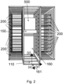
- Fig. 2 shows a transport path 160, here a transport lane, with storage positions 200 arranged on both sides.
- An axis 161 is shown which defines the three spatial directions relevant to the invention.
- the packages 500 are pushed into the storage positions 200 in the y and -y directions.
- the transport unit 150 can be moved in the x and -x directions in the transport lane.
- the vertical position of the transport unit 150 along the z axis can be changed here by a motor (not shown).
- the entire transport unit 150 is not necessarily moved in the z direction. It is conceivable to separate the transport unit 150 into an upper and lower part, whereby only the upper part can be changed in its vertical position.
- Fig. 3 shows a transport unit 150 with two linear guide systems 151, here two conveyor belts, and a middle one with a carriage 157 of an extender 154 hidden here (see Fig. 5 ) connected guide means 156, here also implemented by a conveyor belt.
- the transport unit 150 has a trough shape on its upper side, the edge of the trough being formed by rails 153 pointing in the y direction, which prevent the carrier elements 210 from slipping in the direction of travel and removal in the z direction.
- a carrier element 210 can be pushed into the rails 153 along sliding edges 213 and is secured in the pushed-in state, for example, against slipping during transport.
- the carrier element 210 is connected to the transport unit 150 in the deflected state.
- Fig. 4 the transport unit 150 is made of Fig. 3 shown, the carrier element 210 is only indicated by dashed lines in order to facilitate the engagement of the conveyor belts located engagement elements 152, here drivers, into the engagement structure 212, here engagement groove, of the carrier element 210.
- the in Fig. 5 The transport unit 150 shown additionally has extenders 154 for bridging a gap between the transport unit 150 and the storage position 200.
- the extenders 154 themselves hook into the engagement groove of the carrier element 210 from below.
- the extenders 154 have a common carriage 157 to which they are connected.
- the carriage 157 is embedded in the middle conveyor belt and is pulled along when the conveyor belt is activated.
- the engagement groove is in the state in Fig. 5 shortly before the transfer point 158 of the conveyor belts.
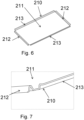
- Fig. 6 shows a trough-like support element 210.
- the long side, along which sliding edges 213 run opposite one another, corresponds in length to the depth of the storage positions 200.
- the engagement structures 212, here engagement grooves, run opposite one another along the short sides.
- a corner of the support element 210 is made of Fig. 6 shown.
- the sliding edge 213 is characterized in that its support surface runs essentially parallel to the carrier base 211 of the carrier element 210.
- the carrier base 211 is preferably designed with a higher coefficient of friction than the sliding edge 213, so that the carrier element 210 can be easily pushed into the storage positions 200, but the packages 500 cannot slip on the carrier base 211.
- the engagement groove for pushing in and pulling out can be seen more closely.
- Fig. 8 shows how the extenders 154 push the carrier element 210 beyond the transport unit 150.
- the carriers that previously pushed the carrier element 210 are now over the transfer point 158 (see Fig. 5 ) of the conveyor belts are folded onto the underside of the conveyor belts. This takes place synchronously with the sliding movement of the extender 154.
- the different acceleration values that arise during rotation are preferably also taken into account. It is possible to connect all three conveyor belts to a common motor (not shown here). Alternatively, it is possible to provide the middle conveyor belt with its own motor.
- Fig. 10 shows a side view of a middle conveyor belt with extender 154.
- the lifting of the extender 154 takes place here by means of two arms 154.2, 154.3 connected via a joint 154.1.
- the lower end of the first arm 154.2 is connected to the carriage 157.
- the angle of the joint 154.1 can be varied via a mechanism connected to the carriage 157. This is preferably controlled electrically via electronics installed in the carriage 157 and not explained in detail here.
- a pressure cylinder or other alternatives known to the person skilled in the art instead of the arms 154.2, 154.3.
- the second arm 154.3 is coupled laterally to the main arm 154.4 of the extender.
- the main arm 154.4 at the end of which there is a driver for engagement in the engagement groove, is connected to the carriage 157 in a rotationally movable manner. Stretching or bending the joint 154.1 changes the height of the main arm 154.4 of the extender 150 and causes it to rise or fall.
- the guide means 156 connected to the extender 154 is shown here as a conveyor belt, whereby the conveyor belt is additionally supported by a guide rod with a guide bushing installed in the carriage 157 to stabilize the carriage 157.
- Fig. 11 the extender 154 is shown in isolation from a different perspective.
- all solutions known to the person skilled in the art for implementing a linear guide 156 for the extender 154 are also conceivable, such as linear guides, spindle drives, pneumatic or hydraulic cylinders, linear motors, belt drives or chain drives.
- An extender 154 of an alternative embodiment of the invention is isolated from a perspective in Fig. 12
- the extender 154 is moved back and forth as a unit, for example with the aid of a linear guide (not shown) supported by lateral guide elements 154.8.
- Cams 154.7 attached to rigid rods 154.6 serve to engage in corresponding engagement structures 212 on support elements 210.
- the cams 154.7 are rotatably mounted and can be moved between a working position in which they are locked in the engagement structure 210 and a rest position, in which they are released from the engagement structure 210, can be switched/activated.
- This configuration of an extender 154 is particularly advantageous for the stability of the transport unit 150.
- the rods 154.6 are not necessarily rigid, but can be telescopically extendable, for example.
- the rigid design of the rods 154.6 has, however, proven to be beneficial when storing and retrieving packages 500 or carrier elements 210.
- Fig. 13 is a transport unit 150 with an extender 154 as shown in Fig. 12 is shown.
- the extender 154 is vertically offset from two external linear guide systems 151, so that a carrier element 210 (not shown here) in a transport position on the transport unit 150 would only rest on the external linear guide systems 151 and the carrier element 210 would not rub on the extender 154.
- the in Fig. 13 proposed transport unit 150 is in Fig. 14 when guiding a carrier element 210 over an end point/transition point 158 (see Fig. 13 ) of the linear guide systems 151.
- the cams 154.7 arranged on the rigid rods 154.6 are locked in the working position in the engagement structure 212 of the carrier element 210.
Landscapes
- Engineering & Computer Science (AREA)
- Business, Economics & Management (AREA)
- Economics (AREA)
- Operations Research (AREA)
- Strategic Management (AREA)
- Entrepreneurship & Innovation (AREA)
- Human Resources & Organizations (AREA)
- Marketing (AREA)
- Mechanical Engineering (AREA)
- Quality & Reliability (AREA)
- Development Economics (AREA)
- Tourism & Hospitality (AREA)
- Physics & Mathematics (AREA)
- General Business, Economics & Management (AREA)
- General Physics & Mathematics (AREA)
- Theoretical Computer Science (AREA)
- Warehouses Or Storage Devices (AREA)
Abstract
Die Erfindung betrifft eine mobile Depoteinrichtung (100) für eine Lagerung und Bereitstellung mehrerer Pakete (500) innerhalb eines vorgesehenen Übergabezeitraums an einem Standort aufweisend- eine Übergabeeinrichtung (110),- Trägerelemente (210) und ein Lager (250) für Trägerelemente,- eine Vielzahl von Lagerpositionen (200),- ein Verbindungsmittel (120) zum Verbinden der Depoteinrichtung (100) mit einem Zuordnungsmittel (300) für eine Zuordnung von Paketidentifikationsmerkmalen zu Lagerpositionen (200),- eine Transporteinheit (150), die sich entlang eines Transportwegs (160) in der mobilen Depoteinrichtung (100) bewegen kann und die Pakete (500) in Lagerpositionen (200) der Depoteinrichtung einbringen kann,- wobei der Transport der Pakete (500) durch die Transporteinheit (150) innerhalb der Depoteinrichtung (100) unter Berücksichtigung der den jeweiligen Paketen (500) anhand der Paketidentifikationsmerkmale zugeordneten Lagerpositionen (200) steuerbar ist.The invention relates to a mobile depot facility (100) for storing and providing a number of packages (500) within a designated handover period at a location, comprising - a handover facility (110), - carrier elements (210) and a warehouse (250) for carrier elements, - a plurality of storage positions (200), - a connecting means (120) for connecting the depot facility (100) to an allocation means (300) for allocating package identification features to storage positions (200), - a transport unit (150) which can move along a transport path (160) in the mobile depot facility (100) and can bring the packages (500) into storage positions (200) of the depot facility, - wherein the transport of the packages (500) by the transport unit (150) within the depot facility (100) takes into account the storage positions allocated to the respective packages (500) based on the package identification features (200) is controllable.
Description
Die Erfindung betrifft eine mobile Depoteinrichtung für eine Lagerung und Bereitstellung mehrerer Pakete innerhalb eines vorgesehenen Übergabezeitraums an einem Standort und ein Verfahren zu ihrem Betreiben.The invention relates to a mobile depot facility for storing and providing several packages within a specified handover period at one location and a method for operating the same.
Im Stand der Technik sind verschiedene Konzepte zur automatischen Einlagerung und Bereitstellung von Paketen in einer Depoteinrichtung bekannt. Beispielsweise ist in
Aus der
Die vorliegende Patentanmeldung beschreibt eine mobile Depoteinrichtung, die dazu dient, Pakete temporär zu lagern und einer Vielzahl von Empfängern an einem Standort zugänglich zu machen. Desweiteren fungiert die mobile Depoteinrichtung dazu, Pakete an einem Standort von einer Vielzahl von Empfängern entgegenzunehmen, temporär zu lagern, an einen Logistikstandort eines Paketdienstleisters zu befördern und dort zu übergeben.The present patent application describes a mobile depot facility that is used to temporarily store packages and make them accessible to a large number of recipients at one location. Furthermore, the mobile depot facility is used to receive packages from a large number of recipients at one location, store them temporarily, transport them to a logistics location of a parcel service provider and hand them over there.
Aufgabe der Erfindung ist es, eine mobile Depoteinrichtung und ein Verfahren zu ihrem Betreiben bereitzustellen, mit dem die Lagerung und Bereitstellung von Paketen möglichst automatisiert und/oder autonom, effizient und mit möglichst geringem ökologischem Fußabdruck durchgeführt werden kann.The object of the invention is to provide a mobile depot facility and a method for operating it, with which the storage and provision of packages can be carried out as automatically and/or autonomously as possible, efficiently and with the smallest possible ecological footprint.
Erfindungsgemäß wird diese Aufgabe durch eine mobile Depoteinrichtung mit den Merkmalen des unabhängigen Anspruches 1 gelöst. Vorteilhafte Weiterbildungen der mobilen Depoteinrichtung ergeben sich aus den Unteransprüchen 2-11. Die Aufgabe wird ferner durch ein Verfahren nach Anspruch 12 gelöst. Eine vorteilhafte Ausführungsform des Verfahrens ergibt sich aus dem Unteranspruch 13. Die in dieser Anmeldung offenbarte mobile Depoteinrichtung bietet eine höhere Standortflexibilität und Erweiterbarkeit. Sie kann an verschiedenen Orten temporär aufgestellt werden, um saisonale oder regionale Spitzen im Paketaufkommen abzudecken. Veränderbare Größen der Paketfächer können an unterschiedliche Bedürfnisse angepasst werden. Dies ermöglicht eine flexible Nutzung je nach Paketgröße und -volumen.According to the invention, this object is achieved by a mobile depot facility with the features of independent claim 1. Advantageous developments of the mobile depot facility arise from subclaims 2-11. The object is further achieved by a method according to claim 12. An advantageous embodiment of the method arises from subclaim 13. The mobile depot facility disclosed in this application offers greater location flexibility and expandability. It can be set up temporarily at different locations in order to cover seasonal or regional peaks in parcel volumes. Variable sizes of the parcel compartments can be adapted to different needs. This enables flexible use depending on the parcel size and volume.
Der Begriff "mobil" ist vorliegend nicht darauf beschränkt, dass die Depoteinrichtung selbstfahrend ist. Vielmehr beinhaltet der Begriff mobil im Sinne der Erfindung, die Depoteinrichtung so auszugestalten, dass ihr Standort (jederzeit) veränderbar ist. Eine Veränderung des Standortes kann beispielsweise dadurch geschehen, dass die Ausgabeeinheit ein Fahrzeug beziehungsweise ein Bestandteil oder Anhänger eines Fahrzeuges ist oder mittels eines Fahrzeuges transportierbar ist.The term "mobile" is not limited to the fact that the depot facility is self-driving. Rather, the term mobile in the sense of the invention includes designing the depot facility in such a way that its location can be changed (at any time). A change in location can occur, for example, if the dispensing unit is a vehicle or a component or trailer of a vehicle or can be transported by means of a vehicle.
Es ist besonders vorteilhaft, die Depoteinrichtung von ihren Abmessungen so zu gestalten, dass sie in einem regulären Straßenverkehr transportierbar und vorzugsweise auf regulären Parkplätzen abstellbar ist. Die Ausgestaltung der Ausgabeeinheit mit entsprechenden Abmessungen ist von vorteilhafter Weise.It is particularly advantageous to design the depot facility in such a way that it can be transported in regular road traffic and preferably parked in regular parking spaces. Designing the dispensing unit with corresponding dimensions is advantageous.
In dieser Anmeldung werden unter Paketen beliebige körperliche Gegenstände verstanden, die transportiert werden können und vorzugsweise bestimmte Abmessungen und/oder ein bestimmtes Gewicht nicht überschreiten.In this application, packages are understood to mean any physical objects that can be transported and preferably do not exceed certain dimensions and/or a certain weight.
Dabei kommen Gegenstände des täglichen Bedarfs wie Verbrauchsmaterialien oder Lebensmittel ebenso in Frage wie technische Gegenstände und Gerätschaften. Bei den Paketen handelt es sich um unverpackte Gegenstände, in eine Produktverpackung verpackte Gegenstände und in eine zusätzliche Transportverpackung umverpackte Gegenstände, wobei bei verpackten und umverpackten Gegenständen das Paket die Verpackung bzw. Umverpackung und den darin verpackten Gegenstand umfasst. Ebenso ist es zweckmäßig, unverpackte Gegenstände, insbesondere Warenobjekte erfindungsgemäß zu bearbeiten. Briefsendungen sowie Werbematerialien und -prospekte sind gegebenenfalls auch Pakete im Sinne dieser Anmeldung. Eine Umverpackung kann dabei entweder anteilig oder vollständig vorgenommen werden. Beispielsweise sind (oben) geöffnete Transportboxen von dem Begriff der Umverpackung ebenfalls umfasst.This includes everyday items such as consumables or foodstuffs as well as technical items and equipment. The packages are unpackaged items, items packed in product packaging and items repackaged in additional transport packaging, whereby in the case of packaged and repackaged items, the package includes the packaging or repackaging and the item packed in it. It is also expedient to process unpackaged items, in particular goods, according to the invention. Letters as well as advertising materials and brochures may also be packages within the meaning of this application. Repackaging can be carried out either partially or completely. For example, opened transport boxes (above) are also included in the term repackaging.
Zur Lagerung und zur Bereitstellung von Paketen ist eine Übergabe der Pakete an die Depoteinrichtung oder durch die Depoteinrichtung erforderlich, wobei die Übergabe insbesondere eine Einlieferung und/oder eine Ausgabe der Pakete sein kann.For the storage and provision of parcels, the parcels must be handed over to the depot facility or by the depot facility, whereby the handover can in particular be a delivery and/or a collection of the parcels.
Die vorliegende Anmeldung betrifft Übergaben von Paketen an Empfänger und/oder Übergaben von Paketen durch Einlieferer. Sofern nicht jeweils spezifiziert ist, dass es sich um eine Übergabe an einen Empfänger handelt, sind auch Übergaben von einem Einlieferer mit umfasst. Ebenso ist dann, wenn nicht jeweils spezifiziert ist, dass es sich um eine Übergabe durch einen Einlieferer handelt, auch eine Übergabe an einen Empfänger mit umfasst. Übergaben durch einen Einlieferer werden in der vorliegenden Anmeldung auch als Einlieferung oder als Annahme bezeichnet, Übergaben an Empfänger auch als Auslieferung.This application concerns handovers of packages to recipients and/or handovers of packages by consignors. Unless it is specified that it is a handover to a recipient, handovers by a consignor are also included. Likewise, unless it is specified that it is a handover by a consignor, handover to a recipient is also included. Handovers by a consignor are also referred to in this application as handover or acceptance, and handovers to recipients are also referred to as delivery.
Sowohl natürliche Personen als auch technische Einheiten können Einlieferer im Kontext der vorliegenden Anmeldung sein. Natürliche Personen oder technische Einheiten, die Pakete an die Depoteinrichtung übergeben, werden im Kontext der vorliegenden Anmeldung auch als Versender bezeichnet. Versender bezeichnet insbesondere solche Einlieferer, die einen Transport von Paketen, gegebenenfalls einschließlich einer Abholung, ggf. die Bezahlung beauftragen, ggf. auch an einem Standort, an dem keine Depoteinrichtung vorhanden ist. Die vorliegende Anmeldung umfasst Ausführungsformen, bei denen die Einlieferer von Paketen Versender sind, mit. Empfänger im Sinne der vorliegenden Erfindung sind Einheiten, an die die mobile Depoteinrichtung Pakete oder sonstige Gegenstände übergibt, beziehungsweise übergeben kann. Sowohl natürliche Personen als auch technische Einheiten können Empfänger im Kontext der vorliegenden Anmeldung sein.Both natural persons and technical units can be consignors in the context of the present application. Natural persons or technical units that hand over packages to the depot facility are also referred to as consignors in the context of the present application. Consignors refer in particular to those consignors who order the transport of packages, possibly including collection, possibly payment, possibly even at a location where there is no depot facility. The present application includes embodiments in which the consignors of packages are consignors. Recipients in the sense of the present invention are units to which the mobile depot facility hands over or can hand over packages or other items. Both natural persons and technical units can be recipients in the context of the present application.
Die erfindungsgemäße mobile Depoteinrichtung für die Lagerung und Bereitstellung mehrerer Pakete innerhalb eines vorgesehenen Übergabezeitraums an einem Standort weist die folgenden Komponenten auf:
- eine Übergabeeinrichtung zum Annehmen und/oder Ausgeben von Paketen,
- Trägerelemente und ein Lager für Trägerelemente, wobei die Trägerelemente einen Trägerboden zur Aufnahme eines Pakets aufweisen und entlang eines gegenüberliegenden Seitenpaars je eine Eingreifstruktur und entlang des anderen gegenüberliegenden Seitenpaars je eine Schiebekante aufweisen,
- eine Vielzahl von Lagerpositionen, wobei die Trägerelemente entlang ihrer Schiebekanten in die Lagerpositionen einschiebbar sind,
- ein Verbindungsmittel zum Verbinden der Depoteinrichtung mit einem Zuordnungsmittel für eine Zuordnung von Paketidentifikationsmerkmalen zu Lagerpositionen,
- eine Transporteinheit, die sich entlang eines Transportwegs in der mobilen Depoteinrichtung bewegen kann und die Pakete in Lagerpositionen der Depoteinrichtung einbringen kann, wobei die Transporteinheit auf wenigstens einem linearen Führungssystem angeordnete Eingriffselemente aufweist, die in eine Eingreifstruktur an wenigstens einer Seite der Trägerelemente eingreifen können und wobei die Transporteinheit wenigstens einen mit dem wenigstens einen linearen Führungssystem verbundenen Motor aufweist, um die Eingriffselemente in Richtung der Lagerpositionen zu verschieben.
- a transfer device for accepting and/or issuing packages,
- Support elements and a bearing for support elements, wherein the support elements have a support base for receiving a package and have an engagement structure along one opposite pair of sides and a sliding edge along the other opposite pair of sides,
- a plurality of storage positions, whereby the support elements can be inserted into the storage positions along their sliding edges,
- a connecting means for connecting the depot facility with an allocation means for assigning parcel identification features to storage positions,
- a transport unit that can move along a transport path in the mobile depot facility and can introduce the packages into storage positions of the depot facility, wherein the transport unit has engagement elements arranged on at least one linear guide system that can engage in an engagement structure on at least one side of the support elements, and wherein the transport unit has at least one motor connected to the at least one linear guide system to displace the engagement elements in the direction of the storage positions.
Der Transport der Pakete durch die Transporteinheit innerhalb der Depoteinrichtung ist dabei unter Berücksichtigung der den jeweiligen Paketen anhand der Paketidentifikationsmerkmale zugeordneten Lagerpositionen steuerbar. Die Transporteinheit ist beispielsweise zweigeteilt in einen oberen Teil und einen unteren Teil, wobei der untere Teil für die Bewegung entlang des Transportwegs verantwortlich ist und der obere Teil für die Einlagerung und Entnahme der Pakete verantwortlich ist. Das lineare Führungssystem ist beispielsweise in eine Decke des oberen Teils integriert. Die Decke kann eine zum Trägerelement passende Geometrie aufweisen und beispielsweise eine Berandung aufweisen, mit der ein aufliegendes Trägerelement gegen Verrutschen gesichert sein kann. Bei der Eingreifstruktur handelt es sich beispielsweise um eine entlang der Seitenkante des Trägerelements verlaufende Eingriffsnut oder um einen Ausschnitt in der Kontur, in der die korrespondierend ausgebildeten Eingriffselemente arretiert werden können. Die Trägerelemente sind beispielsweise wannenförmig mit einer Tiefer von 1 cm ausgebildet. Die wannenartige Ausbildung ist auf den Querschnitt (Seitenansicht) der Trägerelemente bezogen und dient sowohl der Begrenzung der Pakete, sodass sie nicht herunterrutschen können, als auch der besseren platzsparenden Lagerbarkeit. Bei dem Lager für die Trägerelemente kann es sich beispielsweise um eine eigene Vorrichtung handeln. Es ist jedoch auch möglich, die Lagerpositionen als Lager für die Trägerelemente zu nutzen. Das lineare Führungssystem kann beispielsweise durch Linearführungen, bestehend aus einer Schiene und einem Schlitten, der auf der Schiene gleitet, Spindelantriebe mit Spindel und Mutter, pneumatische oder hydraulische Zylinder mit Druckluft oder Hydraulikflüssigkeit, um einen Kolben in einem Zylinder zu bewegen, Linearmotoren, die entlang einer Schiene angebracht sind und eine direkte lineare Bewegung erzeugen können, Riemenantriebe mit Zahnriemen oder einem flachem Riemen, der um Riemenscheiben gewickelt ist, Kettenantriebe oder Förderbänder gebildet sein. Die Transporteinheit weist eine zu den Trägerelementen passende Grundfläche auf, um die Trägerelemente mit darauf befindlichen Paketen sicher zu transportieren. Für einen Einlagerungsvorgang kann die Transporteinheit, nachdem die mobile Depoteinrichtung mitgeteilt bekommen hat, dass ein Einlagerungsvorgang stattfinden soll, an das Lager für Trägerelemente heranfahren und dort ein Trägerelement entnehmen. Dazu fährt die Transporteinheit mittels des wenigstens einen Motors das lineare Führungssystem so weit vor, dass die auf dem linearen Führungssystem angeordneten Eingriffselemente in die Eingreifstruktur eines Trägerelements eingreifen können. Anschließend fährt der Motor das lineare Führungssystem zurück in seine Nullposition und zieht das Trägerelement dabei auf die Transporteinheit. Beim Zurückfahren in die Nullposition fährt vorzugsweise ein weiteres Eingriffselement, das im ausgefahrenen Zustand über den Endpunkt/Umschlagspunkt des linearen Führungssystems hinaus geführt wurde und auf der Unterseite befindlich war, zurück über den Endpunkt/Umschlagspunkt und greift in die gegenüber der ersten Eingreifstruktur befindliche weitere Eingreifstruktur des Trägerelements. Anschließend fährt die Transporteinheit mit dem Trägerelement in die Übergabeeinrichtung und wird dem Einlieferer offenbart. Dieser legt sein zu versendendes Paket auf das Trägerelement. Über ein Verbindungsmittel wird die Depoteinrichtung anschließend mit einem Zuordnungsmittel verbunden, das die Pakete anhand von Paketidentifikationsmerkmalen Lagerpositionen zuordnet, und empfängt dann eine für dieses einzulagernde Paket zugeordnete Lagerposition. Die Depoteinrichtung weist nun die Transporteinheit an, zu dieser Lagerposition zu fahren, woraufhin die Transporteinheit entlang ihres Transportwegs in der Depoteinrichtung fährt, bis sie zu ihrer bestimmten Position fährt. Es kann vorteilhaft sein, vorab zu prüfen, ob das Paket richtig auf das Trägerelement aufgelegt wurde, um ein Herunterfallen des Pakets während des Transports zu verhindern. Richtig liegt das Paket in seiner Ausrichtung im Allgemeinen dann, wenn sein Massepunkt dem Boden des Trägerelements am nächsten ist, das Paket also am flachsten auf dem Trägerelement liegt. Nachdem die Transporteinheit mit Trägerelement und Paket an die Lagerposition herangefahren ist, wird nun mittels des Motors das Förderband ausgelenkt/ausgefahren und das Trägerelement in die Lagerposition eingeschoben.The transport of the packages by the transport unit within the depot facility can be controlled taking into account the storage positions assigned to the respective packages based on the package identification features. The transport unit is, for example, divided into an upper part and a lower part, with the lower part being responsible for the movement along the transport route and the upper part being responsible for storing and removing the packages. The linear guide system is, for example, integrated into a ceiling of the upper part. The ceiling can have a geometry that matches the support element and, for example, have an edge with which a support element resting on it can be secured against slipping. The engagement structure is, for example, an engagement groove running along the side edge of the support element or a cutout in the contour in which the correspondingly designed engagement elements can be locked. The support elements are, for example, trough-shaped with a depth of 1 cm. The trough-like design is based on the cross-section (side view) of the support elements and serves both to limit the packages so that they cannot slide down, and to improve space-saving storage. The storage for the support elements can, for example, be a separate device. However, it is also possible to use the storage positions as storage for the carrier elements. The linear guide system can be formed, for example, by linear guides consisting of a rail and a carriage that slides on the rail, spindle drives with spindle and nut, pneumatic or hydraulic cylinders with compressed air or hydraulic fluid to move a piston in a cylinder, linear motors that are mounted along a rail and can generate a direct linear movement, belt drives with toothed belts or a flat belt wound around pulleys, chain drives or conveyor belts. The transport unit has a base area that fits the carrier elements in order to safely transport the carrier elements with packages on them. For a storage process, the transport unit can drive up to the storage for carrier elements after the mobile depot facility has been informed that a storage process is to take place and remove a carrier element from there. To do this, the transport unit uses the at least one motor to move the linear guide system forwards so far that the engagement elements arranged on the linear guide system can engage the engagement structure of a carrier element. The motor then moves the linear guide system back to its zero position and pulls the carrier element onto the transport unit. When moving back to the zero position, a further engagement element, which in the extended state was guided beyond the end point/transfer point of the linear guide system and was located on the underside, preferably moves back over the end point/transfer point and engages the further engagement structure of the carrier element located opposite the first engagement structure. The transport unit then moves with the carrier element into the transfer device and is revealed to the deliverer. The deliverer places the package to be sent on the carrier element. The depot device is then connected via a connecting means to an allocation means which allocates the packages to storage positions based on package identification features and then receives a storage position allocated to this package to be stored. The depot facility now instructs the transport unit to travel to this storage position, whereupon the transport unit travels along its transport path in the depot facility until it travels to its specific position. It can be advantageous to check in advance whether the package has been correctly placed on the carrier element in order to prevent the package from falling off during transport. The package is generally correctly aligned when its mass point is closest to the base of the carrier element, i.e. the package is at the flattest on the carrier element. After the transport unit with the carrier element and package has moved to the storage position, the conveyor belt is deflected/extended by means of the motor and the carrier element is pushed into the storage position.
Für einen Ausgabevorgang empfängt die Depoteinrichtung zunächst über ihr Verbindungsmittel die zugeordnete Lagerposition von dem Zuordnungsmittel und übermittelt es der Transporteinheit. Diese fährt in analoger Weise mit bis zum Endpunkt/Umschlagspunkt ausgefahrenen Eingriffselementen an die übermittelte Lagerposition heran, fährt das Förderband Richtung Nullposition und zieht das Trägerelement über den Eingriff von Eingriffselementen in die Eingreifstruktur des Trägerelements aus der Lagerposition heraus und auf die Transporteinheit. In der Nullposition sind vorzugsweise Eingriffselemente auf beiden Seiten in die Eingreifstruktur des Trägerelements eingeschoben. Anschließend fährt die Transporteinheit mit Trägerelement und Paket in die Übergabeeinrichtung, offenbart dem Empfänger sein Paket und wartet, bis dieser es entnimmt oder die Transporteinheit eine neue Anweisung erhält. Nach Entnahme des Pakets kann die Transporteinheit an das Lager für Trägerelemente heranfahren und das Trägerelement dort verstauen. Bei einer bevorzugten Ausbildung der mobilen Depoteinrichtung ist das lineare Führungssystem ein Förderband, die Eingriffselemente sind auf dem Förderband angeordnete Mitnehmer und die Eingreifstruktur ist eine Eingriffsnut mit zu den Mitnehmern korrespondierenden Dimensionen. Das Förderband stellt unter anderem deshalb eine bevorzugte Ausbildung dar, weil es hohe Reibwerte aufweisen kann und in die Decke der Transporteinheit integriert werden kann, auf die das Trägerelement aufgelegt werden kann.For an output process, the depot device first receives the assigned storage position from the allocation device via its connecting means and transmits it to the transport unit. This moves in an analogous manner with engagement elements extended to the end point/transfer point to the transmitted storage position, moves the conveyor belt towards the zero position and pulls the carrier element out of the storage position and onto the transport unit via the engagement of engagement elements in the engagement structure of the carrier element. In the zero position, engagement elements are preferably inserted into the engagement structure of the carrier element on both sides. The transport unit then moves with the carrier element and package into the transfer device, reveals its package to the recipient and waits until the recipient removes it or the transport unit receives new instructions. After the package has been removed, the transport unit can move to the storage for carrier elements and stow the carrier element there. In a preferred embodiment of the mobile depot device, the linear guide system is a conveyor belt, the engagement elements are carriers arranged on the conveyor belt and the engagement structure is an engagement groove with dimensions corresponding to the carriers. The conveyor belt is a preferred design because, among other things, it can have high friction values and can be integrated into the ceiling of the transport unit, onto which the carrier element can be placed.
Eine vorteilhafte Weiterbildung der mobilen Depoteinrichtung zeichnet sich dadurch aus, dass die Transporteinheit weiter wenigstens einen ausfahrbaren/ausklappbaren Extender aufweist, der in ausgefahrenem/ausgeklapptem Zustand in die Eingreifstruktur der Trägerelemente eingreift und der geeignet ist, die Trägerelemente über den Endpunkt/Umschlagspunkt des wenigstens einen linearen Führungssystems, insbesondere Förderbands, hinaus mitzunehmen, wobei die Länge des Extenders einen Abstand zwischen dem Endpunkt/Umschlagspunkt des linearen Führungssystems und einer dem Transportweg zugewandten Kante der Lagerpositionen überschreitet und durch Antreiben eines mit dem Extender verbundenen Führungsmittels der Spalt zwischen Transporteinheit und Lagerposition überbrückt wird. Bei dem Führungsmittel kann es sich beispielsweise um ein (weiteres) Förderband handeln. Es sind jedoch auch hubzylindrische, (elektro)magnetische und/oder lineare Antriebe für das Führungsmittel möglich. Der Extender ist beispielsweise zwischen einer abgetauchten und angehobenen Position schaltbar. Mit den Extendern kann sichergestellt werden, dass die Trägerelemente ausreichend tief in die Lagerpositionen eingeschoben werden und die Transporteinheit auch mit hohen Geschwindigkeiten entlang ihres Transportwegs durch die Depoteinrichtung fahren kann, ohne dabei an eingeschobenen Trägerelementen hängen zu bleiben. Die Extender können insbesondere mit einem weiteren Förderband verbunden sein, welches mit einem eigenen Motor verbunden ist. In einer Weiterbildung dieser Anordnung weist die Transporteinheit drei parallel angeordnete Förderbänder auf, wobei auf den jeweils äußeren Förderbändern Eingriffselemente angeordnet sind und das mittlere Förderband mit dem ausfahrbaren/ausklappbaren Extender verbunden ist. Bei einem Einlieferungsvorgang folgt der Extender in einer abgetauchten Position den auf den Förderbändern angeordneten Eingriffselementen, bis sie in der Nähe des Umschlagspunkts sind. Dort kann der Extender angehoben werden und von seiner abgetauchten Position nach oben verlagert werden und in die Eingreifstruktur des Trägerelements eingreifen. Die Aktivierung des Extenders kann beispielsweise über ein elektrisches Signal erfolgen. Der Extender kann beispielsweise aus einem rotierbar gelagerten Arm bestehen, an dessen Seite ein ausfahrbarer Zylinder oder zwei über ein Gelenk verbundene Arme verbunden sind, wobei das Gelenk beispielsweise mittels eines bistabilen Magneten zwischen einer angewinkelten und gestreckten Position geschaltet wird. Es sind jedoch auch alternative Ausbildungen denkbar. In diesem Beispiel würde ein Ausfahren des Zylinders oder ein Strecken des Gelenks den rotierbar gelagerten Arm des Extenders anheben und diesen in die Eingreifstruktur einstecken und in der Eingreifstruktur arretieren.An advantageous further development of the mobile depot facility is characterized in that the transport unit further comprises at least one extendable/foldable extender which, in the extended/folded-out state, engages in the engagement structure of the carrier elements and which is suitable for taking the carrier elements beyond the end point/transfer point of the at least one linear guide system, in particular conveyor belt, wherein the length of the extender exceeds a distance between the end point/transfer point of the linear guide system and an edge of the storage positions facing the transport path and the gap between the transport unit and the storage position is bridged by driving a guide means connected to the extender. The guide means can be for example, it could be a (further) conveyor belt. However, lifting-cylindrical, (electro)magnetic and/or linear drives for the guide means are also possible. The extender can, for example, be switched between a submerged and raised position. The extenders can be used to ensure that the carrier elements are pushed sufficiently deep into the storage positions and that the transport unit can travel at high speeds along its transport path through the depot facility without getting caught on pushed-in carrier elements. The extenders can in particular be connected to a further conveyor belt which is connected to its own motor. In a further development of this arrangement, the transport unit has three conveyor belts arranged in parallel, with engagement elements arranged on the outer conveyor belts and the middle conveyor belt being connected to the extendable/foldable extender. During a delivery process, the extender follows the engagement elements arranged on the conveyor belts in a submerged position until they are close to the transfer point. There, the extender can be lifted and moved upwards from its submerged position and engage the engagement structure of the support element. The extender can be activated, for example, via an electrical signal. The extender can, for example, consist of a rotatably mounted arm, on the side of which an extendable cylinder or two arms connected by a joint are connected, with the joint being switched between an angled and extended position using a bistable magnet, for example. However, alternative designs are also conceivable. In this example, extending the cylinder or extending the joint would raise the rotatably mounted arm of the extender and insert it into the engagement structure and lock it in the engagement structure.
Ebenso würden bei einem Auslagerungsvorgang die äußeren Förderbänder in die maximal ausgelenkte Position verfahren werden, während das mittlere Förderband gerade so weit fährt, dass der Extender im abgetauchten (nicht angehobenen) Zustand exakt unterhalb der Eingreifstruktur befindlich ist. Dies kann beispielsweise sensorisch unterstützt erfolgen. Der Extender würde angehoben und das mittlere Förderband zurückgefahren bis zum Umschlagspunkt der Förderbänder. Ab hier würden die auf den äußeren Förderbändern angeordneten Eingriffselemente in die Eingreifstruktur eingreifen und das Trägerelement in vorbeschriebener Weise auf die Transporteinheit ziehen. Ab dem Punkt, ab dem die Eingriffselemente der äußeren Förderbänder die Bewegung des Trägerelements kontrollieren, kann der Extender wieder abtauchen/abgesenkt werden und in seine Nullposition zurückfahren.Likewise, during a retrieval process, the outer conveyor belts would be moved to the maximum deflected position, while the middle conveyor belt moves just far enough so that the extender is located exactly below the engagement structure in the submerged (not raised) state. This can be done with sensor support, for example. The extender would be raised and the middle conveyor belt would be moved back to the transfer point of the conveyor belts. From here, the engagement elements arranged on the outer conveyor belts would engage in the engagement structure and pull the carrier element onto the transport unit in the manner described above. From the point at which the engagement elements of the outer conveyor belts stop the movement of the support element, the extender can be lowered again and return to its zero position.
In einer bevorzugten Weiterbildung der Erfindung ist der Transportweg als eine Transportgasse ausgebildet und die Transporteinheit kann spiegelsymmetrisch angeordnete Eingriffselemente beidseitig verschieben, wobei die Symmetrieachse entlang der Transportgasse, insbesondere der Mitte der Transportgasse, verläuft. So kann die Transporteinheit Ein- und Auslagervorgänge nach beiden Seiten ausführen. Dass der Transportweg als Transportgasse ausgebildet ist, bedeutet in diesem Fall, dass sich Lagerpositionen beidseitig des Transportweges befinden. Mit dieser Weiterbildung wird die Ausnutzung des limitiert vorhandenen Platzes in der Depoteinrichtung erhöht und die Anzahl der benötigten Transportwege reduziert.In a preferred development of the invention, the transport path is designed as a transport lane and the transport unit can move mirror-symmetrically arranged engagement elements on both sides, with the axis of symmetry running along the transport lane, in particular the middle of the transport lane. The transport unit can thus carry out storage and retrieval processes on both sides. The fact that the transport path is designed as a transport lane means in this case that storage positions are located on both sides of the transport path. This development increases the utilization of the limited space available in the depot facility and reduces the number of transport routes required.
Die erfindungsgemäße mobile Depoteinrichtung zeichnet sich in einer Weiterbildung dadurch aus, dass die Lagerpositionen durch Auflageschienen ausgebildet sind und dass die Transporteinheit ein Mittel aufweist, mit dem eine vertikale Position der Transporteinheit verändert werden kann. Dies vereinfacht den Aufbau der Lagerpositionen in der Art eines Lagerregals. Beispielsweise ist die Transporteinheit zweigeteilt in einen oberen Teil und einen unteren Teil, wobei der untere Teil für die Fortbewegung entlang des Transportwegs beispielsweise mittels eines Antriebsstrangs und damit verbundenen Rädern verantwortlich ist, während der obere Teil von dem unteren Teil mittels eines Motors angehoben werden kann. Der obere Teil beinhaltet eine Auflagefläche für die Trägerelemente, ein lineares Führungssystem, das in die Auflagefläche integriert sein kann, und vorzugsweise Extender. Zusätzlich ist es bevorzugt, wenn die Auflageschienen vertikal äquidistant verteilt sind und der Abstand zwischen zwei benachbarten Auflageschienen 5 cm unterschreitet und bevorzugterweise 3,5 cm beträgt. Je kleiner die Abstände zwischen den Auflageschienen, desto effizienter kann der Raum des Lagerregals ausgenutzt werden. Bei der beispielhaft beschriebenen Ausführung der zweigeteilten Transporteinheit kann der Motor zur Höhenanpassung des oberen Teils als Stepper-Motor ausgebildet sein, wobei die Schrittweite in einfacher Weise auf das Raster abgestimmt werden kann. Prinzipiell kann der Abstand (das Raster) auch kleiner gewählt werden. Beeinflusst wird die Höhe des Rasters durch
- die Höhe des Trägerelements
- den notwendigen Bewegungsfreiraum zwischen zwei leeren Trägerelementen (beispielsweise 5 mm).
- the height of the support element
- the necessary clearance between two empty support elements (e.g. 5 mm).
Das System an sich kann auch in Minitaturgröße gebaut werden. Dann wäre der Mindestabstand des Rasters kleiner als 3,5 cm, beispielsweise 3,5 mm, zwischen zwei übereinanderliegenden Auflageschienen. Beispielsweise kann eine mobile Depoteinrichtung für den Transport von Briefen angepasst sein. Es ist auch denkbar zwei oder mehr Transportgassen mit eigenen Transporteinheiten und Übergabeeinrichtungen in einer mobilen Depoteinrichtung zu verwenden, wobei eine erste Transportgasse ein Raster von 3,5 cm aufweist und für alle Pakete im Sinne dieser Anmeldung geeignet ist und wobei eine zweite Transportgasse ein Raster kleiner als 3,5 cm, beispielsweise 3,5 mm, aufweist und hauptsächlich für Briefe geeignet ist.The system itself can also be built in miniature size. In this case, the minimum distance of the grid would be less than 3.5 cm, for example 3.5 mm, between two support rails lying one above the other. For example, a mobile depot facility can be adapted for the transport of letters. It is also conceivable to use two or more transport lanes with their own transport units and transfer devices in a mobile depot facility, with a first transport lane having a grid of 3.5 cm and being suitable for all packages within the meaning of this application and a second transport lane having a grid smaller than 3.5 cm, for example 3.5 mm, and being mainly suitable for letters.
Gemäß einer vorteilhaften Weiterbildung der Erfindung ist in der mobilen Depoteinrichtung eine Sensoreinheit in der Übergabeeinrichtung angeordnet, die wenigstens ein Paketidentifikationsmerkmal eines einzulagernden Pakets erfassen kann, wobei die Zuordnung des Pakets zu der Lagerposition unter Berücksichtigung des erfassten Paketidentifikationsmerkmals erfolgt, wobei wenigstens eine Höhe des einzulagernden Pakets erfasst wird. Insbesondere wird hier die maximale Höhe des Pakets in der Ausrichtung, in der es auf dem Trägerelement in der Übergabeeinrichtung liegt, erfasst. Mit dieser Weiterbildung kann die Auswahl der Lagerposition optimiert erfolgen. Besonders bevorzugt ist die Kombination dieses Merkmals in die mobile Depoteinrichtung mit lagerregalartig angeordneten Auflageschienen. So kann die Anzahl einlagerbarer Pakete effizient maximiert werden.According to an advantageous development of the invention, a sensor unit is arranged in the transfer device in the mobile depot device, which can detect at least one package identification feature of a package to be stored, the assignment of the package to the storage position taking into account the detected package identification feature, at least one height of the package to be stored being detected. In particular, the maximum height of the package in the orientation in which it lies on the carrier element in the transfer device is detected. With this development, the selection of the storage position can be optimized. The combination of this feature in the mobile depot device with support rails arranged like a storage shelf is particularly preferred. In this way, the number of packages that can be stored can be efficiently maximized.
Gemäß einer weiteren vorteilhaften Ausbildung der Erfindung weist das Trägerelement unterschiedliche Reibwerte an den Schiebekanten und dem Trägerboden auf, wobei der Reibwert des Trägerbodens wesentlich höher als der Reibwert der Schiebekanten ist. Somit wird das Einschieben des Trägerelements in die Lagerpositionen begünstigt und ein Verrutschen des Pakets auf dem Trägerboden des Trägerelements verhindert.According to a further advantageous embodiment of the invention, the carrier element has different friction values on the sliding edges and the carrier base, whereby the friction value of the carrier base is significantly higher than the friction value of the sliding edges. This facilitates the insertion of the carrier element into the storage positions and prevents the package from slipping on the carrier base of the carrier element.
Gemäß einer weiteren vorteilhaften Ausbildung der Erfindung weist die Transporteinheit ein Haltemittel auf, mit dem das Trägerelement gegen Verschieben oder Abheben gesichert wird. In einer vorteilhaften Weiterbildung dieser mobilen Depoteinrichtung weist das Haltemittel eine Schiene auf, in die die Schiebekante des Trägerelements eingeschoben werden kann. Die Schiene hält das Trägerelement entlang der Schiebekante dabei in vertikaler Richtung fest. Mit dieser Ausbildung wird eine (versehentliche) Entnahme des Trägerelements in der Übergabeeinrichtung durch einen Empfänger und ein Verrutschen des Trägerelements in Richtung des Transportwegs beim Transport verhindert.According to a further advantageous embodiment of the invention, the transport unit has a holding means with which the carrier element is secured against displacement or lifting. In an advantageous development of this mobile depot device, the holding means has a rail into which the sliding edge of the carrier element can be pushed. The rail holds the carrier element along the sliding edge in a vertical direction. With this design, (accidental) removal of the carrier element in the transfer device by a Receiver and prevents the carrier element from slipping in the direction of the transport path during transport.
Gemäß einem weiteren Aspekt der Erfindung wird auch ein Verfahren zum Betreiben einer mobilen Depoteinrichtung, insbesondere einer mobilen Depoteinrichtung nach einer der vorbeschriebenen Ausbildungen bereitgestellt. Das Verfahren zeichnet sich dadurch aus, dass
für einen Einlagerungsvorgang eines Pakets
- eine Transporteinheit ein Trägerelement einem Lager für Trägerelemente entnimmt und in der Transporteinheit arretiert,
- die Transporteinheit in eine Übergabeeinrichtung der mobilen Depoteinrichtung fährt,
- die Übergabeeinrichtung geöffnet wird, so dass ein Einlieferer ein Paket auf den Trägerboden des Trägerelements legen kann,
- die Transporteinheit wartet, bis das Paket auf das Trägerelement gelegt ist,
- eine in Abhängigkeit wenigstens eines Paketidentifikationsmerkmals zugeordnete Lagerposition empfangen wird,
- die Transporteinheit entlang eines Transportwegs in der mobilen Depoteinrichtung gesteuert wird, bis sich die Transporteinheit in einer der empfangenen Lagerposition gegenüberliegenden Position befindet,
- ein Motor wenigstens ein lineares Führungssystem antreibt, das über Eingriffselemente in eine Eingreifstruktur des Trägerelements greift und das Trägerelement auf seinen Schiebekanten in die Lagerposition eingeschoben wird,
und dass
für einen Auslagerungsvorgang eines Pakets, - anhand eines Paketidentifikationsmerkmals eine Lagerposition empfangen wird,
- die Transporteinheit entlang des Transportwegs in der mobilen Depoteinrichtung gesteuert wird, bis sich die Transporteinheit in einer der empfangenen Lagerposition gegenüberliegenden Position befindet,
- der Motor das wenigstens eine lineare Führungssystem antreibt, das über Eingriffselemente in die Eingreifstruktur des in der Lagerposition befindlichen Trägerelements eingreift und das das Trägerelement auf seinen Schiebekanten aus der Lagerposition herauszieht und auf der Transporteinheit festhält, vorzugsweise arretiert,
- die Transporteinheit mit dem Paket in die Übergabeeinrichtung der mobilen Depoteinrichtung fährt,
- die Übergabeeinrichtung geöffnet wird, so dass ein Empfänger das Paket entnehmen kann und
- die Transporteinheit das Trägerelement in das Lager für die Trägerelemente einbringt.
for a storage process of a package
- a transport unit removes a carrier element from a carrier element warehouse and locks it in the transport unit,
- the transport unit drives into a transfer facility of the mobile depot facility,
- the transfer device is opened so that a consignor can place a parcel on the carrier base of the carrier element,
- the transport unit waits until the package is placed on the carrier element,
- a storage position assigned depending on at least one parcel identification feature is received,
- the transport unit is guided along a transport path in the mobile depot facility until the transport unit is in a position opposite the received storage position,
- a motor drives at least one linear guide system which engages via engagement elements in an engagement structure of the carrier element and the carrier element is pushed into the storage position on its sliding edges,
and that
for an outsourcing process of a package, - a storage position is received based on a package identification feature,
- the transport unit is guided along the transport path in the mobile depot facility until the transport unit is in a position opposite the received storage position,
- the motor drives the at least one linear guide system, which engages via engagement elements in the engagement structure of the carrier element located in the storage position and which pulls the carrier element out of the storage position on its sliding edges and holds it on the transport unit, preferably locking it,
- the transport unit with the package drives into the transfer facility of the mobile depot facility,
- the transfer device is opened so that a recipient can remove the package and
- the transport unit brings the carrier element into the storage area for the carrier elements.
Gemäß einer vorteilhaften Weiterbildung des Verfahrens wird
- bei einem Einlagerungsvorgang beim Einschieben des Trägerelements in die Lagerposition, bevor oder während die auf wenigstens einem linearen Führungssystem befindlichen Eingriffselemente sich an einem Endpunkt/Umschlagspunkt des linearen Führungssystems aus der Eingreifstruktur herauslösen, wenigstens ein Extender ausgeklappt/ausgefahren und angehoben, sodass er von unten in die Eingreifstruktur eingreift und das Trägerelement über den Endpunkt/Umschlagspunkt des linearen Führungssystems hinaus in die Lagerposition einschiebt, wobei der Extender vor einem Zurückfahren abgesenkt wird, ehe der Extender und das lineare Führungssystem in ihre Ausgangsposition zurückfahren,
und - bei einem Auslagerungsvorgang beim Herausziehen des Trägerelements aus der Lagerposition der Extender in einer abgesenkten Position so weit ausgelenkt, bis der Extender bei einem Anheben von unten in die Eingreifstruktur des Trägerelements eingreifen würde, der Extender angehoben und anschließend zurückgefahren, bis sich die Eingreifstruktur des Trägerelements über dem Endpunkt/Umschlagspunkt des linearen Führungssystems befindet, wobei das wenigstens eine mit Eingriffselementen ausgestattete lineare Führungssystem zurückfährt, bis die Eingriffselemente in die Eingreifstruktur des Trägerelements eingreifen, so dass der Extender eingeklappt/abgetaucht werden kann und das Trägerelement über die Eingriffselemente auf die Transporteinheit gezogen und festgehalten, vorzugsweise arretiert, wird.
- during a storage process when pushing the carrier element into the storage position, before or while the engagement elements located on at least one linear guide system are released from the engagement structure at an end point/turnover point of the linear guide system, at least one extender is unfolded/extended and raised so that it engages the engagement structure from below and pushes the carrier element beyond the end point/turnover point of the linear guide system into the storage position, wherein the extender is lowered before retraction before the extender and the linear guide system return to their starting position,
and - During a retrieval process when the carrier element is pulled out of the storage position, the extender is deflected in a lowered position until the extender would engage in the engagement structure of the carrier element if it were lifted from below, the extender is raised and then moved back until the engagement structure of the carrier element is located above the end point/turnover point of the linear guide system, wherein the at least one linear guide system equipped with engagement elements moves back until the engagement elements engage in the engagement structure of the carrier element, so that the extender can be folded in/submerged and the carrier element is pulled onto the transport unit via the engagement elements and held, preferably locked.
Die vorliegende Erfindung wird nachfolgend anhand bevorzugter Ausführungsbeispiele unter Bezugnahme auf die beigefügten Figuren näher erläutert. Es ist jedoch zu beachten, dass die beschriebenen Ausführungsbeispiele lediglich zur Veranschaulichung dienen und die Erfindung nicht darauf beschränkt ist. Ein Fachmann wird verstehen, dass verschiedene Modifikationen, Änderungen und Variationen der vorliegenden Erfindung möglich sind, die von dem dargestellten Ausführungsbeispiel abweichen können. Solche Modifikationen, Änderungen und Variationen werden als im Rahmen der Erfindung liegend angesehen und werden durch die beigefügten Ansprüche abgedeckt. Ein Fachmann wird in der Lage sein, verschiedene sinnvolle Kombinationen der Merkmale der vorliegenden Erfindung in Abhängigkeit von den spezifischen Anforderungen und Gegebenheiten zu erkennen.
- A) Mobile Depoteinrichtung mit einem Lager für Trägerelemente, insbesondere mobile Depoteinrichtung nach einer in dieser Anmeldung beschriebenen Ausführungsformen, wobei Lagerpositionen als Lager für die Trägerelemente verwendbar sind.
- B) Mobile Depoteinrichtung, insbesondere mobile Depoteinrichtung nach einer in dieser Anmeldung beschriebenen Ausführungsformen, wobei zwei oder mehr Transportgassen mit eigenen Transporteinheiten und Übergabeeinrichtungen in einer mobilen Depoteinrichtung angeordnet sind, wobei eine erste Transportgasse ein erstes Raster aufweist und wobei eine zweite Transportgasse ein zweites Raster aufweist, wobei das zweite Raster wesentlich kleiner als das erste Raster ist.
- C) Mobile Depoteinrichtung nach B), wobei die erste Transportgasse ein Raster von 3,5 cm aufweist und für alle Pakete im Sinne dieser Anmeldung geeignet ist und wobei eine zweite Transportgasse ein Raster kleiner als 3,5 cm, beispielsweise 3,5 mm, aufweist und hauptsächlich für Briefe geeignet ist.
- A) Mobile depot device with a storage for carrier elements, in particular mobile depot device according to one of the embodiments described in this application, wherein storage positions can be used as storage for the carrier elements.
- B) Mobile depot device, in particular mobile depot device according to one of the embodiments described in this application, wherein two or more transport lanes with their own transport units and transfer devices are arranged in a mobile depot device, wherein a first transport lane has a first grid and wherein a second transport lane has a second grid, wherein the second grid is substantially smaller than the first grid.
- C) Mobile depot device according to B), wherein the first transport lane has a grid of 3.5 cm and is suitable for all packages within the meaning of this application and wherein a second transport lane has a grid smaller than 3.5 cm, for example 3.5 mm, and is mainly suitable for letters.
Von den Abbildungen zeigt:
- Fig. 1
- eine erfindungsgemäße mobile Depoteinrichtung,
- Fig. 2
- eine Transportgasse mit beidseitig angeordneten Lagerpositionen,
- Fig. 3
- eine Transporteinheit einer erfindungsgemäßen mobilen Depoteinrichtung,
- Fig. 4
- Mitnehmer auf zwei außen angeordneten Förderbändern für die Übertragung eines Trägerelements von einer Transporteinheit in eine Lagerposition (Ein- und Auslagerung),
- Fig. 5
- synchron zu Mitnehmern arbeitende Extender in Vorbereitung der Überbrückung eines Spaltes zwischen Transporteinheit und Lagerposition,
- Fig. 6
- eine Ansicht auf ein Trägerelement,
- Fig. 7
- eine Detailansicht eines Trägerelements,
- Fig. 8
- Extender, die ein Transportelement über die Transporteinheit hinaus schieben,
- Fig. 9
- Extender, die ein Transportelement noch weiter über die Transporteinheit hinaus schieben,
- Fig. 10
- eine Seitenansicht eines mittleren Förderbands mit Extender,
- Fig. 11
- eine isolierte Ansicht des Extenders,
- Fig. 12
- eine isolierte Ansicht eines weiteren Extenders,
- Fig. 13
- eine Transporteinheit mit Extender,
- Fig. 14
- eine Transporteinheit mit ausgefahrenem Extender in Eingriff mit Trägerelement.
- Fig. 1
- a mobile depot device according to the invention,
- Fig. 2
- a transport lane with storage positions arranged on both sides,
- Fig. 3
- a transport unit of a mobile depot device according to the invention,
- Fig. 4
- Carriers on two externally arranged conveyor belts for the transfer of a carrier element from a transport unit to a storage position (storage and retrieval),
- Fig. 5
- extenders working synchronously with carriers in preparation for bridging a gap between the transport unit and the storage position,
- Fig. 6
- a view of a support element,
- Fig. 7
- a detailed view of a support element,
- Fig. 8
- Extenders that push a transport element beyond the transport unit,
- Fig. 9
- Extenders that push a transport element even further beyond the transport unit,
- Fig. 10
- a side view of a middle conveyor belt with extender,
- Fig. 11
- an isolated view of the extender,
- Fig. 12
- an isolated view of another extender,
- Fig. 13
- a transport unit with extender,
- Fig. 14
- a transport unit with extended extender in engagement with the carrier element.
Zunächst werden die Bezugszeichen allgemein beschrieben. Auf die einzelnen Zeichen wird im Zusammenhang mit den jeweiligen Abbildungen hingewiesen. In den nachfolgenden Darstellungen werden identische Bezugszeichen verwendet, um entsprechende Elemente eindeutig zu kennzeichnen.First, the reference symbols are described in general terms. The individual symbols are referred to in connection with the respective illustrations. In the following illustrations, identical reference symbols are used to clearly identify corresponding elements.
Bei der in den
Für einen Einlagerungsvorgang fährt eine Transporteinheit 150, nachdem die mobile Depoteinrichtung 100 mitgeteilt bekommen hat, dass ein Einlagerungsvorgang stattfinden soll, an ein Lager 250 für Trägerelemente 210 heran und entnimmt dort ein Trägerelement 210. Dazu fährt die Transporteinheit 150 zunächst einen Extender 154 aus, bis er sich unterhalb einer Eingreifstruktur 212 eines Trägerelements 210 befindet, aktiviert den Extender 154, um in die Eingreifstruktur 212 zu greifen und fährt anschließend ein mit dem Extender 154 verbundenes Führungsmittel 156 zurück, bis sich die Eingreifstruktur 156 über dem einem Endpunkt/Umschlagspunkt 158 des linearen Führungssystems 151 befindet und die auf dem linearen Führungssystem 151 angeordneten Eingriffselemente 152 in die Eingreifstruktur 212 eines Trägerelements 210 eingreifen können. Anschließend fährt der Motor das lineare Führungssystem 151 zurück in seine Nullposition und zieht das Trägerelement 210 dabei auf die Transporteinheit 150. Beim Zurückfahren in die Nullposition fährt vorzugsweise ein weiteres Eingriffselement 152, das im ausgefahrenen Zustand über den Endpunkt/Umschlagspunkt 158 des linearen Führungssystems 151 hinaus geführt wurde und auf der Unterseite befindlich war, zurück über den Endpunkt/Umschlagspunkt 158 und greift in die gegenüber der ersten Eingreifstruktur 212 befindliche weitere Eingreifstruktur 212 des Trägerelements 210. Anschließend fährt die Transporteinheit 150 mit dem Trägerelement 210 in die Übergabeeinrichtung 110 und wird dem Einlieferer offenbart. Dieser legt sein zu versendendes Paket 500 auf das Trägerelement 210. Über ein Verbindungsmittel 120 wird die Depoteinrichtung 100 anschließend mit einem Zuordnungsmittel 300 verbunden, das die Pakete 500 anhand von Paketidentifikationsmerkmalen Lagerpositionen 200 zuordnet, und empfängt dann eine für dieses einzulagernde Paket 500 zugeordnete Lagerposition 200. Die Depoteinrichtung 100 weist nun die Transporteinheit 150 an, zu dieser Lagerposition 200 zu fahren, woraufhin die Transporteinheit 150 entlang ihres Transportwegs 160 in der Depoteinrichtung 100 fährt, bis sie ihre bestimmte Position erreicht. Nachdem die Transporteinheit 150 mit Trägerelement 210 und Paket 500 an die Lagerposition 200 herangefahren ist, wird nun mittels des Motors das Förderband ausgelenkt/ausgefahren und das Trägerelement 210 in die Lagerposition 200 eingeschoben. Die Extender 154 werden spätestens ab dem Endpunkt/Umschlagspunkt 158 angehoben und schieben das Trägerelement 210 vollständig in die Lagerposition 200 ein.For a storage process, a
Für einen Ausgabevorgang empfängt die Depoteinrichtung 100 zunächst über ihr Verbindungsmittel 120 die zugeordnete Lagerposition 200 von dem Zuordnungsmittel 300 und übermittelt es der Transporteinheit 150. Das lineare Führungssystem 151 wird in die maximal ausgelenkte Position verfahren, während das mit dem Extender 154 verbundene Führungsmittel 156 gerade so weit fährt, dass der Extender 154 im abgetauchten (nicht angehobenen) Zustand exakt unterhalb der Eingreifstruktur 212 befindlich ist. Der Extender 154 wird angehoben und das mittlere Förderband zurückgefahren bis zum Endpunkt/Umschlagspunkt 158 der Förderbänder. Ab hier greifen die auf den äußeren Förderbändern angeordneten Eingriffselemente 152 in die Eingreifstruktur 212 ein und das Trägerelement 210 wird in vorbeschriebener Weise auf die Transporteinheit 150 gezogen. Ab dem Punkt, ab dem die Eingriffselemente 152 der äußeren Förderbänder die Bewegung des Trägerelements 210 kontrollieren, kann der Extender 154 wieder abtauchen/abgesenkt werden und in seine Nullposition zurückfahren. In der Nullposition sind vorzugsweise Eingriffselemente 152 auf beiden Seiten in die Eingreifstruktur 212 des Trägerelements 210 eingeschoben. Anschließend fährt die Transporteinheit 150 mit Trägerelement 210 und Paket 500 in die Übergabeeinrichtung 110, offenbart dem Empfänger sein Paket 500 und wartet, bis dieser es entnimmt oder die Transporteinheit 150 eine neue Anweisung erhält. Nach Entnahme des Pakets 500 kann die Transporteinheit 150 an das Lager 250 für Trägerelemente 210 heranfahren und das Trägerelement 210 dort verstauen.For an output process, the
In
Die in
In
In
In
Ein Extender 154 einer alternativen Ausbildungsform der Erfindung ist isoliert aus einer Perspektive in
In
Die in
Die hier gezeigten Ausführungsformen stellen nur Beispiele für die vorliegende Erfindung dar und dürfen daher nicht einschränkend verstanden werden. Alternative durch den Fachmann in Erwägung gezogene Ausführungsformen sind gleichermaßen vom Schutzbereich der vorliegenden Erfindung umfasst.The embodiments shown here are only examples of the present invention and should therefore not be understood as limiting. Alternative embodiments considered by those skilled in the art are equally included within the scope of the present invention.
- 100100
- Mobile DepoteinrichtungMobile depot facility
- 110110
- Übergabeeinrichtungtransfer device
- 111111
- Sensoreinheitsensor unit
- 120120
- Verbindungsmittelconnecting means
- 150150
- Transporteinheittransport unit
- 151151
- Lineares FührungssystemLinear guide system
- 152152
- Eingriffselementengagement element
- 153153
- Schienenrails
- 154154
- Extenderextender
- 154.1154.1
- Gelenkjoint
- 154.2154.2
- Armarm
- 154.3154.3
- Armarm
- 154.4154.4
- Hauptarmmain arm
- 154.6154.6
- Stabrod
- 154.7154.7
- Nockencam
- 154.8154.8
- Führungselementguide element
- 156156
- Führungsmittelmanagement tools
- 157157
- SchlittenSleds
- 158158
- Endpunkt/Umschlagspunktend point/transfer point
- 160160
- Transportwegtransport route
- 161161
- Achseaxis
- 200200
- Lagerpositionstorage position
- 210210
- Trägerelementsupport element
- 211211
- Trägerbodensupport floor
- 212212
- Eingreifstrukturintervention structure
- 213213
- Schiebekantensliding edges
- 250250
- Lagercamp
- 300300
- Zuordnungsmittelallocation means
- 500500
- Paketpackage
Claims (13)
dadurch gekennzeichnet, dass
das lineare Führungssystem (151) ein Förderband ist, die Eingriffselemente (152) auf dem Förderband angeordnete Mitnehmer sind und die Eingreifstruktur (212) eine Eingriffsnut mit zu den Mitnehmern korrespondierenden Dimensionen ist.Mobile depot device (100) according to claim 1,
characterized in that
the linear guide system (151) is a conveyor belt, the engagement elements (152) are carriers arranged on the conveyor belt and the engagement structure (212) is an engagement groove with dimensions corresponding to the carriers.
dadurch gekennzeichnet, dass
die Transporteinheit (150) weiter wenigstens einen ausfahrbaren/ausklappbaren Extender (154) aufweist, der in angehobenem/aktiviertem Zustand in die Eingreifstruktur (212) der Trägerelemente (210) eingreift und der geeignet ist, die Trägerelemente (210) über einen Endpunkt/Umschlagspunkt (158) des wenigstens einen linearen Führungssystems (151) hinaus mitzunehmen, wobei die Länge des Extenders (154) einen Abstand zwischen dem Endpunkt/Umschlagspunkt (158) des linearen Führungssystems (151) und einer dem Transportweg (160) zugewandten Kante der Lagerpositionen (200) überschreitet und durch Antreiben eines mit dem Extender (154) verbundenen Führungsmittels (156) der Spalt zwischen Transporteinheit (150) und Lagerposition (200) durch den Extender (154) überbrückt wird.Mobile depot device (100) according to claim 1 or 2,
characterized in that
the transport unit (150) further comprises at least one extendable/foldable extender (154) which, in the raised/activated state, engages in the engagement structure (212) of the carrier elements (210) and which is suitable for taking the carrier elements (210) beyond an end point/turnover point (158) of the at least one linear guide system (151), wherein the length of the extender (154) exceeds a distance between the end point/turnover point (158) of the linear guide system (151) and an edge of the storage positions (200) facing the transport path (160), and by driving a guide means (156) connected to the extender (154), the gap between the transport unit (150) and the storage position (200) is bridged by the extender (154).
dadurch gekennzeichnet, dass
die Transporteinheit (150) drei parallel angeordnete Förderbänder aufweist, wobei auf den jeweils äußeren Förderbändern Eingriffselemente (152) angeordnet sind und ein mittleres Förderband mit dem ausfahrbaren/ausklappbaren Extender (154) verbunden ist.Mobile depot device (100) according to one of the preceding claims,
characterized in that
the transport unit (150) has three conveyor belts arranged in parallel, wherein engagement elements (152) are arranged on the respective outer conveyor belts and a middle conveyor belt is connected to the extendable/foldable extender (154).
dadurch gekennzeichnet, dass
der Transportweg (160) als eine Transportgasse ausgebildet ist und die Transporteinheit (150) spiegelsymmetrisch angeordnete Eingriffselemente (152) beidseitig verschieben kann, wobei die Symmetrieachse entlang der Transportgasse verläuft.Mobile depot device (100) according to one of the preceding claims,
characterized in that
the transport path (160) is designed as a transport lane and the transport unit (150) can move mirror-symmetrically arranged engagement elements (152) on both sides, wherein the axis of symmetry runs along the transport lane.
dadurch gekennzeichnet, dass
die Lagerpositionen (200) durch Auflageschienen ausgebildet sind und dass die Transporteinheit (150) ein Mittel aufweist, mit dem eine vertikale Position der Transporteinheit (150) verändert werden kann.Mobile depot device (100) according to one of the preceding claims,
characterized in that
the storage positions (200) are formed by support rails and that the transport unit (150) has a means with which a vertical position of the transport unit (150) can be changed.
dadurch gekennzeichnet, dass
die Auflageschienen vertikal äquidistant verteilt sind und der Abstand zwischen zwei benachbarten Auflageschienen 5 cm unterschreitet und bevorzugterweise 3,5 cm beträgt.Mobile depot device (100) according to claim 6,
characterized in that
the support rails are distributed vertically equidistant and the distance between two adjacent support rails is less than 5 cm and preferably 3.5 cm.
dadurch gekennzeichnet, dass
eine Sensoreinheit (111) in der Übergabeeinrichtung (110) angeordnet ist, die wenigstens ein Paketidentifikationsmerkmal eines einzulagernden Pakets (500) erfassen kann, wobei die Zuordnung des Pakets (500) zu der Lagerposition (200) unter Berücksichtigung des erfassten Paketidentifikationsmerkmals erfolgt, wobei wenigstens eine Höhe des einzulagernden Pakets (500) erfasst wird.Mobile depot device (100) according to one of the preceding claims,
characterized in that
a sensor unit (111) is arranged in the transfer device (110), which can detect at least one package identification feature of a package (500) to be stored, wherein the assignment of the package (500) to the storage position (200) takes place taking into account the detected package identification feature, wherein at least one height of the package (500) to be stored is detected.
dadurch gekennzeichnet, dass
das Trägerelement (210) unterschiedliche Reibwerte an den Schiebekanten (213) und dem Trägerboden (211) aufweisen, wobei der Reibwert des Trägerbodens (211) wesentlich höher als der Reibwert der Schiebekanten (213) ist, und vorzugsweise so hoch ist, dass sich die Pakete nicht auf dem Trägerelement bewegen.Mobile depot device (100) according to one of the preceding claims,
characterized in that
the carrier element (210) has different friction values on the sliding edges (213) and the carrier base (211), wherein the friction value of the carrier base (211) is substantially higher than the friction value of the sliding edges (213), and is preferably so high that the packages do not move on the carrier element.
dadurch gekennzeichnet, dass
die Transporteinheit (150) ein Haltemittel aufweist, mit dem das Trägerelement (210) gegen Verschieben oder Abheben gesichert ist.Mobile depot device (100) according to one of the preceding claims,
characterized in that
the transport unit (150) has a holding means with which the carrier element (210) is secured against displacement or lifting.
dadurch gekennzeichnet, dass
das Haltemittel Schienen (153) aufweist, in die die Schiebekanten (213) des Trägerelements (210) eingeschoben werden können.Mobile depot device (100) according to claim 10,
characterized in that
the holding means has rails (153) into which the sliding edges (213) of the carrier element (210) can be inserted.
dadurch gekennzeichnet, dass
für einen Einlagerungsvorgang eines Pakets (500)
und dass
für einen Auslagerungsvorgang eines Pakets (500),
characterized in that
for a storage process of a package (500)
and that
for a packet removal process (500),
und dass
and that
Priority Applications (1)
| Application Number | Priority Date | Filing Date | Title |
|---|---|---|---|
| PCT/EP2024/073880 WO2025045856A1 (en) | 2023-08-28 | 2024-08-27 | Mobile depot facility and method for operating same |
Applications Claiming Priority (1)
| Application Number | Priority Date | Filing Date | Title |
|---|---|---|---|
| EP23193783 | 2023-08-28 |
Publications (1)
| Publication Number | Publication Date |
|---|---|
| EP4517618A1 true EP4517618A1 (en) | 2025-03-05 |
Family
ID=87847796
Family Applications (1)
| Application Number | Title | Priority Date | Filing Date |
|---|---|---|---|
| EP23198562.3A Pending EP4517618A1 (en) | 2023-08-28 | 2023-09-20 | Mobile depot device and method for its operation |
Country Status (1)
| Country | Link |
|---|---|
| EP (1) | EP4517618A1 (en) |
Citations (4)
| Publication number | Priority date | Publication date | Assignee | Title |
|---|---|---|---|---|
| EP1438641B1 (en) | 2001-10-09 | 2006-05-03 | Deutsche Post AG | Packet box electronic device and logistic system |
| EP1959406A1 (en) | 2007-02-16 | 2008-08-20 | Deutsche Post AG | Locker facility, logistics system and method for operating the locker facility |
| WO2019090196A1 (en) * | 2017-11-03 | 2019-05-09 | Box Bot Inc. | Package receiving and delivery system |
| DE202021004056U1 (en) * | 2020-11-20 | 2022-09-22 | Innovative Robot Delivery Gmbh | Depot facility and system suitable for handing over a large number of parcels to a number of recipients and/or for receiving a large number of parcels from a number of posters |
-
2023
- 2023-09-20 EP EP23198562.3A patent/EP4517618A1/en active Pending
Patent Citations (4)
| Publication number | Priority date | Publication date | Assignee | Title |
|---|---|---|---|---|
| EP1438641B1 (en) | 2001-10-09 | 2006-05-03 | Deutsche Post AG | Packet box electronic device and logistic system |
| EP1959406A1 (en) | 2007-02-16 | 2008-08-20 | Deutsche Post AG | Locker facility, logistics system and method for operating the locker facility |
| WO2019090196A1 (en) * | 2017-11-03 | 2019-05-09 | Box Bot Inc. | Package receiving and delivery system |
| DE202021004056U1 (en) * | 2020-11-20 | 2022-09-22 | Innovative Robot Delivery Gmbh | Depot facility and system suitable for handing over a large number of parcels to a number of recipients and/or for receiving a large number of parcels from a number of posters |
Similar Documents
| Publication | Publication Date | Title |
|---|---|---|
| EP2436621B1 (en) | Shelf stocking vehicle | |
| EP4052962B1 (en) | Shelving arrangement | |
| DE102011014394C5 (en) | Circular roaming for a storage and picking system | |
| EP0847939B1 (en) | Method of order picking and device therefor | |
| AT511490A1 (en) | BAY WAREHOUSE SYSTEM | |
| EP3286111A1 (en) | Method for transferring part-load consignments to a storage rack for storage, and storage system | |
| EP1964792A2 (en) | Method and system for supplying transport units from a depot in a desired order onto at least one collecting track | |
| DE102011012424A1 (en) | Storage and picking system with shuttle | |
| WO2003011722A1 (en) | Method and system for commissioning comprising a shelf and a shelf and shelf control device associated therewith | |
| EP3452390B1 (en) | Storage system and method for operating same | |
| DE102013005116A1 (en) | Automated picking station for manual picking of items from storage containers in a order container | |
| DE102011002322A1 (en) | Storage and retrieval device for storage shelf used in pharmacy, has transport element which is moved in transport direction through feed drive, and packages are slid onto tray surface in transport direction | |
| DE4433234C1 (en) | Arrangement for removal of stack units from container on board aircraft | |
| EP2753558B1 (en) | Order-picking station and method for order-picking of articles from a loading aid | |
| DE102012220193A1 (en) | Storage goods extractor for an automatic storage system | |
| DE9103197U1 (en) | Storage and retrieval machine for high-bay warehouses | |
| EP1423314B1 (en) | Shelving storage facility comprising slides in the shelves | |
| AT525328B1 (en) | Method for operating a shelf store, and a shelf store, carriage and lifting unit for this | |
| DE102014206590A1 (en) | Logistics system and method for transferring and / or taking over goods between a vehicle and a warehouse | |
| DE102008064533A1 (en) | Load-receiving device for a stacker crane, conveyor with a stacker crane and method for operating a stacker crane | |
| DE19719651A1 (en) | Method and device for picking | |
| EP4517618A1 (en) | Mobile depot device and method for its operation | |
| WO2025045856A1 (en) | Mobile depot facility and method for operating same | |
| DE9103198U1 (en) | Storage and retrieval machine for high-bay small parts warehouse | |
| EP1564160B1 (en) | Apparatus for storing articles |
Legal Events
| Date | Code | Title | Description |
|---|---|---|---|
| PUAI | Public reference made under article 153(3) epc to a published international application that has entered the european phase |
Free format text: ORIGINAL CODE: 0009012 |
|
| STAA | Information on the status of an ep patent application or granted ep patent |
Free format text: STATUS: THE APPLICATION HAS BEEN PUBLISHED |
|
| AK | Designated contracting states |
Kind code of ref document: A1 Designated state(s): AL AT BE BG CH CY CZ DE DK EE ES FI FR GB GR HR HU IE IS IT LI LT LU LV MC ME MK MT NL NO PL PT RO RS SE SI SK SM TR |
|
| STAA | Information on the status of an ep patent application or granted ep patent |
Free format text: STATUS: REQUEST FOR EXAMINATION WAS MADE |
|
| 17P | Request for examination filed |
Effective date: 20250905 |