EP4517618A1 - Dispositif de dépôt mobile et son procédé de fonctionnement - Google Patents
Dispositif de dépôt mobile et son procédé de fonctionnement Download PDFInfo
- Publication number
- EP4517618A1 EP4517618A1 EP23198562.3A EP23198562A EP4517618A1 EP 4517618 A1 EP4517618 A1 EP 4517618A1 EP 23198562 A EP23198562 A EP 23198562A EP 4517618 A1 EP4517618 A1 EP 4517618A1
- Authority
- EP
- European Patent Office
- Prior art keywords
- transport unit
- carrier element
- extender
- elements
- package
- Prior art date
- Legal status (The legal status is an assumption and is not a legal conclusion. Google has not performed a legal analysis and makes no representation as to the accuracy of the status listed.)
- Pending
Links
Images


Classifications
-
- G—PHYSICS
- G06—COMPUTING OR CALCULATING; COUNTING
- G06Q—INFORMATION AND COMMUNICATION TECHNOLOGY [ICT] SPECIALLY ADAPTED FOR ADMINISTRATIVE, COMMERCIAL, FINANCIAL, MANAGERIAL OR SUPERVISORY PURPOSES; SYSTEMS OR METHODS SPECIALLY ADAPTED FOR ADMINISTRATIVE, COMMERCIAL, FINANCIAL, MANAGERIAL OR SUPERVISORY PURPOSES, NOT OTHERWISE PROVIDED FOR
- G06Q10/00—Administration; Management
- G06Q10/08—Logistics, e.g. warehousing, loading or distribution; Inventory or stock management
- G06Q10/083—Shipping
-
- B—PERFORMING OPERATIONS; TRANSPORTING
- B65—CONVEYING; PACKING; STORING; HANDLING THIN OR FILAMENTARY MATERIAL
- B65G—TRANSPORT OR STORAGE DEVICES, e.g. CONVEYORS FOR LOADING OR TIPPING, SHOP CONVEYOR SYSTEMS OR PNEUMATIC TUBE CONVEYORS
- B65G1/00—Storing articles, individually or in orderly arrangement, in warehouses or magazines
- B65G1/02—Storage devices
Definitions
- the invention relates to a mobile depot facility for storing and providing several packages within a specified handover period at one location and a method for operating the same.
- EP 1 959 406 A1 a parcel station with lockers and a control unit for monitoring access authorizations was shown.
- EP 1 438 641 B1 an electronic parcel compartment system with a large number of electronic parcel compartments is known, with a control unit being assigned to each of several electronic parcel compartments.
- This known electronic parcel compartment system is characterized in that a central control unit is provided for controlling the control units, with the central control unit containing a means for a changeable assignment of the parcel compartments to the control units.
- the parcel compartment system disclosed in this European patent has rigid lockers and is also stationary.
- the present patent application describes a mobile depot facility that is used to temporarily store packages and make them accessible to a large number of recipients at one location. Furthermore, the mobile depot facility is used to receive packages from a large number of recipients at one location, store them temporarily, transport them to a logistics location of a parcel service provider and hand them over there.
- the object of the invention is to provide a mobile depot facility and a method for operating it, with which the storage and provision of packages can be carried out as automatically and/or autonomously as possible, efficiently and with the smallest possible ecological footprint.
- this object is achieved by a mobile depot facility with the features of independent claim 1.
- Advantageous developments of the mobile depot facility arise from subclaims 2-11.
- the object is further achieved by a method according to claim 12.
- An advantageous embodiment of the method arises from subclaim 13.
- the mobile depot facility disclosed in this application offers greater location flexibility and expandability. It can be set up temporarily at different locations in order to cover seasonal or regional peaks in parcel volumes. Variable sizes of the parcel compartments can be adapted to different needs. This enables flexible use depending on the parcel size and volume.
- mobile is not limited to the fact that the depot facility is self-driving. Rather, the term mobile in the sense of the invention includes designing the depot facility in such a way that its location can be changed (at any time). A change in location can occur, for example, if the dispensing unit is a vehicle or a component or trailer of a vehicle or can be transported by means of a vehicle.
- the depot facility in such a way that it can be transported in regular road traffic and preferably parked in regular parking spaces. Designing the dispensing unit with corresponding dimensions is advantageous.
- packages are understood to mean any physical objects that can be transported and preferably do not exceed certain dimensions and/or a certain weight.
- the packages are unpackaged items, items packed in product packaging and items repackaged in additional transport packaging, whereby in the case of packaged and repackaged items, the package includes the packaging or repackaging and the item packed in it. It is also expedient to process unpackaged items, in particular goods, according to the invention. Letters as well as advertising materials and brochures may also be packages within the meaning of this application. Repackaging can be carried out either partially or completely. For example, opened transport boxes (above) are also included in the term repackaging.
- the parcels For the storage and provision of parcels, the parcels must be handed over to the depot facility or by the depot facility, whereby the handover can in particular be a delivery and/or a collection of the parcels.
- This application concerns handovers of packages to recipients and/or handovers of packages by consignors. Unless it is specified that it is a handover to a recipient, handovers by a consignor are also included. Likewise, unless it is specified that it is a handover by a consignor, handover to a recipient is also included. Handovers by a consignor are also referred to in this application as handover or acceptance, and handovers to recipients are also referred to as delivery.
- Both natural persons and technical units can be consignors in the context of the present application.
- Natural persons or technical units that hand over packages to the depot facility are also referred to as consignors in the context of the present application.
- Consignors refer in particular to those consignors who order the transport of packages, possibly including collection, possibly payment, possibly even at a location where there is no depot facility.
- the present application includes embodiments in which the consignors of packages are consignors.
- Recipients in the sense of the present invention are units to which the mobile depot facility hands over or can hand over packages or other items. Both natural persons and technical units can be recipients in the context of the present application.
- the transport of the packages by the transport unit within the depot facility can be controlled taking into account the storage positions assigned to the respective packages based on the package identification features.
- the transport unit is, for example, divided into an upper part and a lower part, with the lower part being responsible for the movement along the transport route and the upper part being responsible for storing and removing the packages.
- the linear guide system is, for example, integrated into a ceiling of the upper part.
- the ceiling can have a geometry that matches the support element and, for example, have an edge with which a support element resting on it can be secured against slipping.
- the engagement structure is, for example, an engagement groove running along the side edge of the support element or a cutout in the contour in which the correspondingly designed engagement elements can be locked.
- the support elements are, for example, trough-shaped with a depth of 1 cm.
- the trough-like design is based on the cross-section (side view) of the support elements and serves both to limit the packages so that they cannot slide down, and to improve space-saving storage.
- the storage for the support elements can, for example, be a separate device. However, it is also possible to use the storage positions as storage for the carrier elements.
- the linear guide system can be formed, for example, by linear guides consisting of a rail and a carriage that slides on the rail, spindle drives with spindle and nut, pneumatic or hydraulic cylinders with compressed air or hydraulic fluid to move a piston in a cylinder, linear motors that are mounted along a rail and can generate a direct linear movement, belt drives with toothed belts or a flat belt wound around pulleys, chain drives or conveyor belts.
- the transport unit has a base area that fits the carrier elements in order to safely transport the carrier elements with packages on them. For a storage process, the transport unit can drive up to the storage for carrier elements after the mobile depot facility has been informed that a storage process is to take place and remove a carrier element from there.
- the transport unit uses the at least one motor to move the linear guide system forwards so far that the engagement elements arranged on the linear guide system can engage the engagement structure of a carrier element.
- the motor then moves the linear guide system back to its zero position and pulls the carrier element onto the transport unit.
- a further engagement element which in the extended state was guided beyond the end point/transfer point of the linear guide system and was located on the underside, preferably moves back over the end point/transfer point and engages the further engagement structure of the carrier element located opposite the first engagement structure.
- the transport unit then moves with the carrier element into the transfer device and is revealed to the deliverer. The deliverer places the package to be sent on the carrier element.
- the depot device is then connected via a connecting means to an allocation means which allocates the packages to storage positions based on package identification features and then receives a storage position allocated to this package to be stored.
- the depot facility now instructs the transport unit to travel to this storage position, whereupon the transport unit travels along its transport path in the depot facility until it travels to its specific position. It can be advantageous to check in advance whether the package has been correctly placed on the carrier element in order to prevent the package from falling off during transport.
- the package is generally correctly aligned when its mass point is closest to the base of the carrier element, i.e. the package is at the flattest on the carrier element. After the transport unit with the carrier element and package has moved to the storage position, the conveyor belt is deflected/extended by means of the motor and the carrier element is pushed into the storage position.
- the depot device first receives the assigned storage position from the allocation device via its connecting means and transmits it to the transport unit. This moves in an analogous manner with engagement elements extended to the end point/transfer point to the transmitted storage position, moves the conveyor belt towards the zero position and pulls the carrier element out of the storage position and onto the transport unit via the engagement of engagement elements in the engagement structure of the carrier element. In the zero position, engagement elements are preferably inserted into the engagement structure of the carrier element on both sides.
- the transport unit then moves with the carrier element and package into the transfer device, reveals its package to the recipient and waits until the recipient removes it or the transport unit receives new instructions. After the package has been removed, the transport unit can move to the storage for carrier elements and stow the carrier element there.
- the linear guide system is a conveyor belt
- the engagement elements are carriers arranged on the conveyor belt
- the engagement structure is an engagement groove with dimensions corresponding to the carriers.
- the conveyor belt is a preferred design because, among other things, it can have high friction values and can be integrated into the ceiling of the transport unit, onto which the carrier element can be placed.
- the transport unit further comprises at least one extendable/foldable extender which, in the extended/folded-out state, engages in the engagement structure of the carrier elements and which is suitable for taking the carrier elements beyond the end point/transfer point of the at least one linear guide system, in particular conveyor belt, wherein the length of the extender exceeds a distance between the end point/transfer point of the linear guide system and an edge of the storage positions facing the transport path and the gap between the transport unit and the storage position is bridged by driving a guide means connected to the extender.
- the guide means can be for example, it could be a (further) conveyor belt.
- the extender can, for example, be switched between a submerged and raised position.
- the extenders can be used to ensure that the carrier elements are pushed sufficiently deep into the storage positions and that the transport unit can travel at high speeds along its transport path through the depot facility without getting caught on pushed-in carrier elements.
- the extenders can in particular be connected to a further conveyor belt which is connected to its own motor.
- the transport unit has three conveyor belts arranged in parallel, with engagement elements arranged on the outer conveyor belts and the middle conveyor belt being connected to the extendable/foldable extender.
- the extender follows the engagement elements arranged on the conveyor belts in a submerged position until they are close to the transfer point. There, the extender can be lifted and moved upwards from its submerged position and engage the engagement structure of the support element.
- the extender can be activated, for example, via an electrical signal.
- the extender can, for example, consist of a rotatably mounted arm, on the side of which an extendable cylinder or two arms connected by a joint are connected, with the joint being switched between an angled and extended position using a bistable magnet, for example.
- extending the cylinder or extending the joint would raise the rotatably mounted arm of the extender and insert it into the engagement structure and lock it in the engagement structure.
- the outer conveyor belts would be moved to the maximum deflected position, while the middle conveyor belt moves just far enough so that the extender is located exactly below the engagement structure in the submerged (not raised) state. This can be done with sensor support, for example.
- the extender would be raised and the middle conveyor belt would be moved back to the transfer point of the conveyor belts.
- the engagement elements arranged on the outer conveyor belts would engage in the engagement structure and pull the carrier element onto the transport unit in the manner described above. From the point at which the engagement elements of the outer conveyor belts stop the movement of the support element, the extender can be lowered again and return to its zero position.
- the transport path is designed as a transport lane and the transport unit can move mirror-symmetrically arranged engagement elements on both sides, with the axis of symmetry running along the transport lane, in particular the middle of the transport lane.
- the transport unit can thus carry out storage and retrieval processes on both sides.
- the fact that the transport path is designed as a transport lane means in this case that storage positions are located on both sides of the transport path.
- the system itself can also be built in miniature size.
- the minimum distance of the grid would be less than 3.5 cm, for example 3.5 mm, between two support rails lying one above the other.
- a mobile depot facility can be adapted for the transport of letters. It is also conceivable to use two or more transport lanes with their own transport units and transfer devices in a mobile depot facility, with a first transport lane having a grid of 3.5 cm and being suitable for all packages within the meaning of this application and a second transport lane having a grid smaller than 3.5 cm, for example 3.5 mm, and being mainly suitable for letters.
- a sensor unit is arranged in the transfer device in the mobile depot device, which can detect at least one package identification feature of a package to be stored, the assignment of the package to the storage position taking into account the detected package identification feature, at least one height of the package to be stored being detected.
- the maximum height of the package in the orientation in which it lies on the carrier element in the transfer device is detected.
- the carrier element has different friction values on the sliding edges and the carrier base, whereby the friction value of the carrier base is significantly higher than the friction value of the sliding edges. This facilitates the insertion of the carrier element into the storage positions and prevents the package from slipping on the carrier base of the carrier element.
- the transport unit has a holding means with which the carrier element is secured against displacement or lifting.
- the holding means has a rail into which the sliding edge of the carrier element can be pushed. The rail holds the carrier element along the sliding edge in a vertical direction.
- the linear guide system 151 is a conveyor belt
- the engagement elements 152 are carriers arranged on the conveyor belt
- the engagement structure 212 is an engagement groove with dimensions corresponding to the carriers.
- the transport unit 150 is designed to travel in the depot device 100 along a transport path 160 and to change its vertical position.
- the depot device 100 is then connected via a connecting means 120 to an allocation means 300, which allocates the packages 500 to storage positions 200 based on package identification features, and then receives a storage position 200 allocated for this package 500 to be stored.
- the depot device 100 now instructs the transport unit 150 to travel to this storage position 200, whereupon the transport unit 150 travels along its transport path 160 in the depot device 100 until it reaches its specific position.
- the conveyor belt is now deflected/extended by means of the motor and the carrier element 210 is pushed into the storage position 200.
- the extenders 154 are raised at the latest from the end point/transfer point 158 and push the carrier element 210 completely into the storage position 200.
- Fig. 1 shows a mobile depot device 100 according to the invention, having a transfer device 110, carrier elements 210, a warehouse 250 for the carrier elements 210, a plurality of storage positions 200, a connecting means 120 and a transport unit 150 that can travel from the transfer device 110 to the storage positions 200.
- the mobile depot device 100 uses the connecting means 120 to communicate with an allocation means 300 in order to be able to allocate the storage positions 200 to packages 500 based on package identification features.
- a sensor unit 111 for detecting a height of a package 500 is shown in the transfer device 110.
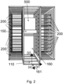
- Fig. 2 shows a transport path 160, here a transport lane, with storage positions 200 arranged on both sides.
- An axis 161 is shown which defines the three spatial directions relevant to the invention.
- the packages 500 are pushed into the storage positions 200 in the y and -y directions.
- the transport unit 150 can be moved in the x and -x directions in the transport lane.
- the vertical position of the transport unit 150 along the z axis can be changed here by a motor (not shown).
- the entire transport unit 150 is not necessarily moved in the z direction. It is conceivable to separate the transport unit 150 into an upper and lower part, whereby only the upper part can be changed in its vertical position.
- Fig. 3 shows a transport unit 150 with two linear guide systems 151, here two conveyor belts, and a middle one with a carriage 157 of an extender 154 hidden here (see Fig. 5 ) connected guide means 156, here also implemented by a conveyor belt.
- the transport unit 150 has a trough shape on its upper side, the edge of the trough being formed by rails 153 pointing in the y direction, which prevent the carrier elements 210 from slipping in the direction of travel and removal in the z direction.
- a carrier element 210 can be pushed into the rails 153 along sliding edges 213 and is secured in the pushed-in state, for example, against slipping during transport.
- the carrier element 210 is connected to the transport unit 150 in the deflected state.
- Fig. 4 the transport unit 150 is made of Fig. 3 shown, the carrier element 210 is only indicated by dashed lines in order to facilitate the engagement of the conveyor belts located engagement elements 152, here drivers, into the engagement structure 212, here engagement groove, of the carrier element 210.
- the in Fig. 5 The transport unit 150 shown additionally has extenders 154 for bridging a gap between the transport unit 150 and the storage position 200.
- the extenders 154 themselves hook into the engagement groove of the carrier element 210 from below.
- the extenders 154 have a common carriage 157 to which they are connected.
- the carriage 157 is embedded in the middle conveyor belt and is pulled along when the conveyor belt is activated.
- the engagement groove is in the state in Fig. 5 shortly before the transfer point 158 of the conveyor belts.
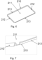
- Fig. 6 shows a trough-like support element 210.
- the long side, along which sliding edges 213 run opposite one another, corresponds in length to the depth of the storage positions 200.
- the engagement structures 212, here engagement grooves, run opposite one another along the short sides.
- a corner of the support element 210 is made of Fig. 6 shown.
- the sliding edge 213 is characterized in that its support surface runs essentially parallel to the carrier base 211 of the carrier element 210.
- the carrier base 211 is preferably designed with a higher coefficient of friction than the sliding edge 213, so that the carrier element 210 can be easily pushed into the storage positions 200, but the packages 500 cannot slip on the carrier base 211.
- the engagement groove for pushing in and pulling out can be seen more closely.
- Fig. 8 shows how the extenders 154 push the carrier element 210 beyond the transport unit 150.
- the carriers that previously pushed the carrier element 210 are now over the transfer point 158 (see Fig. 5 ) of the conveyor belts are folded onto the underside of the conveyor belts. This takes place synchronously with the sliding movement of the extender 154.
- the different acceleration values that arise during rotation are preferably also taken into account. It is possible to connect all three conveyor belts to a common motor (not shown here). Alternatively, it is possible to provide the middle conveyor belt with its own motor.
- Fig. 10 shows a side view of a middle conveyor belt with extender 154.
- the lifting of the extender 154 takes place here by means of two arms 154.2, 154.3 connected via a joint 154.1.
- the lower end of the first arm 154.2 is connected to the carriage 157.
- the angle of the joint 154.1 can be varied via a mechanism connected to the carriage 157. This is preferably controlled electrically via electronics installed in the carriage 157 and not explained in detail here.
- a pressure cylinder or other alternatives known to the person skilled in the art instead of the arms 154.2, 154.3.
- the second arm 154.3 is coupled laterally to the main arm 154.4 of the extender.
- the main arm 154.4 at the end of which there is a driver for engagement in the engagement groove, is connected to the carriage 157 in a rotationally movable manner. Stretching or bending the joint 154.1 changes the height of the main arm 154.4 of the extender 150 and causes it to rise or fall.
- the guide means 156 connected to the extender 154 is shown here as a conveyor belt, whereby the conveyor belt is additionally supported by a guide rod with a guide bushing installed in the carriage 157 to stabilize the carriage 157.
- Fig. 11 the extender 154 is shown in isolation from a different perspective.
- all solutions known to the person skilled in the art for implementing a linear guide 156 for the extender 154 are also conceivable, such as linear guides, spindle drives, pneumatic or hydraulic cylinders, linear motors, belt drives or chain drives.
- An extender 154 of an alternative embodiment of the invention is isolated from a perspective in Fig. 12
- the extender 154 is moved back and forth as a unit, for example with the aid of a linear guide (not shown) supported by lateral guide elements 154.8.
- Cams 154.7 attached to rigid rods 154.6 serve to engage in corresponding engagement structures 212 on support elements 210.
- the cams 154.7 are rotatably mounted and can be moved between a working position in which they are locked in the engagement structure 210 and a rest position, in which they are released from the engagement structure 210, can be switched/activated.
- This configuration of an extender 154 is particularly advantageous for the stability of the transport unit 150.
- the rods 154.6 are not necessarily rigid, but can be telescopically extendable, for example.
- the rigid design of the rods 154.6 has, however, proven to be beneficial when storing and retrieving packages 500 or carrier elements 210.
- Fig. 13 is a transport unit 150 with an extender 154 as shown in Fig. 12 is shown.
- the extender 154 is vertically offset from two external linear guide systems 151, so that a carrier element 210 (not shown here) in a transport position on the transport unit 150 would only rest on the external linear guide systems 151 and the carrier element 210 would not rub on the extender 154.
- the in Fig. 13 proposed transport unit 150 is in Fig. 14 when guiding a carrier element 210 over an end point/transition point 158 (see Fig. 13 ) of the linear guide systems 151.
- the cams 154.7 arranged on the rigid rods 154.6 are locked in the working position in the engagement structure 212 of the carrier element 210.
Landscapes
- Engineering & Computer Science (AREA)
- Business, Economics & Management (AREA)
- Economics (AREA)
- Operations Research (AREA)
- Strategic Management (AREA)
- Entrepreneurship & Innovation (AREA)
- Human Resources & Organizations (AREA)
- Marketing (AREA)
- Mechanical Engineering (AREA)
- Quality & Reliability (AREA)
- Development Economics (AREA)
- Tourism & Hospitality (AREA)
- Physics & Mathematics (AREA)
- General Business, Economics & Management (AREA)
- General Physics & Mathematics (AREA)
- Theoretical Computer Science (AREA)
- Warehouses Or Storage Devices (AREA)
Priority Applications (1)
| Application Number | Priority Date | Filing Date | Title |
|---|---|---|---|
| PCT/EP2024/073880 WO2025045856A1 (fr) | 2023-08-28 | 2024-08-27 | Installation de dépôt mobile et son procédé de fonctionnement |
Applications Claiming Priority (1)
| Application Number | Priority Date | Filing Date | Title |
|---|---|---|---|
| EP23193783 | 2023-08-28 |
Publications (1)
| Publication Number | Publication Date |
|---|---|
| EP4517618A1 true EP4517618A1 (fr) | 2025-03-05 |
Family
ID=87847796
Family Applications (1)
| Application Number | Title | Priority Date | Filing Date |
|---|---|---|---|
| EP23198562.3A Pending EP4517618A1 (fr) | 2023-08-28 | 2023-09-20 | Dispositif de dépôt mobile et son procédé de fonctionnement |
Country Status (1)
| Country | Link |
|---|---|
| EP (1) | EP4517618A1 (fr) |
Citations (4)
| Publication number | Priority date | Publication date | Assignee | Title |
|---|---|---|---|---|
| EP1438641B1 (fr) | 2001-10-09 | 2006-05-03 | Deutsche Post AG | Dispositif electronique de casiers pour colis et systeme logistique |
| EP1959406A1 (fr) | 2007-02-16 | 2008-08-20 | Deutsche Post AG | Installation de coffres multiples, système logistique et procédé de fonctionnement de l'installation de coffres multiples |
| WO2019090196A1 (fr) * | 2017-11-03 | 2019-05-09 | Box Bot Inc. | Système de réception et de distribution de paquets |
| DE202021004056U1 (de) * | 2020-11-20 | 2022-09-22 | Innovative Robot Delivery Gmbh | Depoteinrichtung und System geeignet zur Übergabe einer Vielzahl von Paketen an mehrere Empfänger und/oder zur Entgegennahme einer Vielzahl von Paketen von mehreren Einlieferern |
-
2023
- 2023-09-20 EP EP23198562.3A patent/EP4517618A1/fr active Pending
Patent Citations (4)
| Publication number | Priority date | Publication date | Assignee | Title |
|---|---|---|---|---|
| EP1438641B1 (fr) | 2001-10-09 | 2006-05-03 | Deutsche Post AG | Dispositif electronique de casiers pour colis et systeme logistique |
| EP1959406A1 (fr) | 2007-02-16 | 2008-08-20 | Deutsche Post AG | Installation de coffres multiples, système logistique et procédé de fonctionnement de l'installation de coffres multiples |
| WO2019090196A1 (fr) * | 2017-11-03 | 2019-05-09 | Box Bot Inc. | Système de réception et de distribution de paquets |
| DE202021004056U1 (de) * | 2020-11-20 | 2022-09-22 | Innovative Robot Delivery Gmbh | Depoteinrichtung und System geeignet zur Übergabe einer Vielzahl von Paketen an mehrere Empfänger und/oder zur Entgegennahme einer Vielzahl von Paketen von mehreren Einlieferern |
Similar Documents
| Publication | Publication Date | Title |
|---|---|---|
| EP2436621B1 (fr) | Véhicule pour le stockage des rayonnages | |
| EP4052962B1 (fr) | Agencement d'étagère | |
| DE102011014394C5 (de) | Zirkulares Roaming für ein Lager- und Kommissioniersystem | |
| EP0847939B1 (fr) | Dispositif et procédé pour rassembler et préparer des marchandises en détail | |
| AT511490A1 (de) | Regallagersystem | |
| EP3286111A1 (fr) | Procédé de mise en stock de charges isolées dans un rayonnage de stockage et système de stockage | |
| EP1964792A2 (fr) | Procédé et système destinés à la préparation d'unités de transport à partir d'un stockage selon une suite prédéterminée souhaitée sur au moins une trajectoire de collecte | |
| DE102011012424A1 (de) | Lager- und Kommissioniersystem mit Shuttle | |
| WO2003011722A1 (fr) | Procede et installation pour preparer des commandes a l'aide d'un rayonnage et d'un gerbeur associe | |
| EP3452390B1 (fr) | Système de stockage et procédé permettant de faire fonctionner ledit système | |
| DE102013005116A1 (de) | Automatisierter Kommissionierplatz zum manuellen Kommissionieren von Artikeln aus Lagerbehältern in einem Auftragsbehälter | |
| DE102011002322A1 (de) | Regalbedienvorrichtung für ein Regallager und Verfahren zum Betrieb einer Regalbedienvorrichtung | |
| DE4433234C1 (de) | Anordnung zur Entnahme von Stapeleinheiten aus einem Behälter an Bord eines Flugzeuges und Stapeleinheit | |
| EP2753558B1 (fr) | Poste de préparation de commande et méthode de préparation de commande d'articles avec aide au chargement | |
| DE102012220193A1 (de) | Lagergut-Extraktor für ein automatisches Lagersystem | |
| DE9103197U1 (de) | Regalbediengerät für Hochregallager | |
| EP1423314B1 (fr) | Magasin a rayonnage comportant des tiroirs montes dans les compartiments de rayonnage | |
| AT525328B1 (de) | Verfahren zum Betreiben eines Regallagers, sowie ein Regallager, Fahrwagen und Hubeinheit hierfür | |
| DE102014206590A1 (de) | Logistiksystem und Verfahren zur Übergabe und/oder Übernahme von Waren zwischen einem Fahrzeug und einem Warenlager | |
| DE102008064533A1 (de) | Lastaufnahmevorrichtung für ein Regalbediengerät, Förderanlage mit einem Regalbediengerät und Verfahren zum Betreiben eines Regalbediengeräts | |
| DE19719651A1 (de) | Verfahren und Vorrichtung zum Kommissionieren | |
| EP4517618A1 (fr) | Dispositif de dépôt mobile et son procédé de fonctionnement | |
| WO2025045856A1 (fr) | Installation de dépôt mobile et son procédé de fonctionnement | |
| DE9103198U1 (de) | Regalbediengerät für Hochregal-Kleinteilelager | |
| EP1564160B1 (fr) | Dispositif de stockage d'objets |
Legal Events
| Date | Code | Title | Description |
|---|---|---|---|
| PUAI | Public reference made under article 153(3) epc to a published international application that has entered the european phase |
Free format text: ORIGINAL CODE: 0009012 |
|
| STAA | Information on the status of an ep patent application or granted ep patent |
Free format text: STATUS: THE APPLICATION HAS BEEN PUBLISHED |
|
| AK | Designated contracting states |
Kind code of ref document: A1 Designated state(s): AL AT BE BG CH CY CZ DE DK EE ES FI FR GB GR HR HU IE IS IT LI LT LU LV MC ME MK MT NL NO PL PT RO RS SE SI SK SM TR |
|
| STAA | Information on the status of an ep patent application or granted ep patent |
Free format text: STATUS: REQUEST FOR EXAMINATION WAS MADE |
|
| 17P | Request for examination filed |
Effective date: 20250905 |