EP4517318A2 - Optisches system für kapillarelektrophorese - Google Patents
Optisches system für kapillarelektrophorese Download PDFInfo
- Publication number
- EP4517318A2 EP4517318A2 EP24213815.4A EP24213815A EP4517318A2 EP 4517318 A2 EP4517318 A2 EP 4517318A2 EP 24213815 A EP24213815 A EP 24213815A EP 4517318 A2 EP4517318 A2 EP 4517318A2
- Authority
- EP
- European Patent Office
- Prior art keywords
- capillaries
- capillary
- output beams
- beams
- array
- Prior art date
- Legal status (The legal status is an assumption and is not a legal conclusion. Google has not performed a legal analysis and makes no representation as to the accuracy of the status listed.)
- Pending
Links
Images


Classifications
-
- G—PHYSICS
- G01—MEASURING; TESTING
- G01N—INVESTIGATING OR ANALYSING MATERIALS BY DETERMINING THEIR CHEMICAL OR PHYSICAL PROPERTIES
- G01N27/00—Investigating or analysing materials by the use of electric, electrochemical, or magnetic means
- G01N27/26—Investigating or analysing materials by the use of electric, electrochemical, or magnetic means by investigating electrochemical variables; by using electrolysis or electrophoresis
- G01N27/416—Systems
- G01N27/447—Systems using electrophoresis
- G01N27/44756—Apparatus specially adapted therefor
-
- G—PHYSICS
- G01—MEASURING; TESTING
- G01N—INVESTIGATING OR ANALYSING MATERIALS BY DETERMINING THEIR CHEMICAL OR PHYSICAL PROPERTIES
- G01N27/00—Investigating or analysing materials by the use of electric, electrochemical, or magnetic means
- G01N27/26—Investigating or analysing materials by the use of electric, electrochemical, or magnetic means by investigating electrochemical variables; by using electrolysis or electrophoresis
- G01N27/416—Systems
- G01N27/447—Systems using electrophoresis
- G01N27/44704—Details; Accessories
- G01N27/44717—Arrangements for investigating the separated zones, e.g. localising zones
- G01N27/44721—Arrangements for investigating the separated zones, e.g. localising zones by optical means
-
- G—PHYSICS
- G01—MEASURING; TESTING
- G01N—INVESTIGATING OR ANALYSING MATERIALS BY DETERMINING THEIR CHEMICAL OR PHYSICAL PROPERTIES
- G01N21/00—Investigating or analysing materials by the use of optical means, i.e. using sub-millimetre waves, infrared, visible or ultraviolet light
- G01N21/62—Systems in which the material investigated is excited whereby it emits light or causes a change in wavelength of the incident light
- G01N21/63—Systems in which the material investigated is excited whereby it emits light or causes a change in wavelength of the incident light optically excited
- G01N21/64—Fluorescence; Phosphorescence
- G01N21/645—Specially adapted constructive features of fluorimeters
-
- G—PHYSICS
- G01—MEASURING; TESTING
- G01N—INVESTIGATING OR ANALYSING MATERIALS BY DETERMINING THEIR CHEMICAL OR PHYSICAL PROPERTIES
- G01N27/00—Investigating or analysing materials by the use of electric, electrochemical, or magnetic means
- G01N27/26—Investigating or analysing materials by the use of electric, electrochemical, or magnetic means by investigating electrochemical variables; by using electrolysis or electrophoresis
- G01N27/416—Systems
- G01N27/447—Systems using electrophoresis
- G01N27/44704—Details; Accessories
-
- G—PHYSICS
- G01—MEASURING; TESTING
- G01N—INVESTIGATING OR ANALYSING MATERIALS BY DETERMINING THEIR CHEMICAL OR PHYSICAL PROPERTIES
- G01N27/00—Investigating or analysing materials by the use of electric, electrochemical, or magnetic means
- G01N27/26—Investigating or analysing materials by the use of electric, electrochemical, or magnetic means by investigating electrochemical variables; by using electrolysis or electrophoresis
- G01N27/416—Systems
- G01N27/447—Systems using electrophoresis
- G01N27/44704—Details; Accessories
- G01N27/44743—Introducing samples
-
- G—PHYSICS
- G01—MEASURING; TESTING
- G01N—INVESTIGATING OR ANALYSING MATERIALS BY DETERMINING THEIR CHEMICAL OR PHYSICAL PROPERTIES
- G01N27/00—Investigating or analysing materials by the use of electric, electrochemical, or magnetic means
- G01N27/26—Investigating or analysing materials by the use of electric, electrochemical, or magnetic means by investigating electrochemical variables; by using electrolysis or electrophoresis
- G01N27/416—Systems
- G01N27/447—Systems using electrophoresis
- G01N27/44756—Apparatus specially adapted therefor
- G01N27/44791—Microapparatus
-
- G—PHYSICS
- G01—MEASURING; TESTING
- G01N—INVESTIGATING OR ANALYSING MATERIALS BY DETERMINING THEIR CHEMICAL OR PHYSICAL PROPERTIES
- G01N21/00—Investigating or analysing materials by the use of optical means, i.e. using sub-millimetre waves, infrared, visible or ultraviolet light
- G01N21/62—Systems in which the material investigated is excited whereby it emits light or causes a change in wavelength of the incident light
- G01N21/63—Systems in which the material investigated is excited whereby it emits light or causes a change in wavelength of the incident light optically excited
- G01N21/64—Fluorescence; Phosphorescence
- G01N2021/6417—Spectrofluorimetric devices
-
- G—PHYSICS
- G01—MEASURING; TESTING
- G01N—INVESTIGATING OR ANALYSING MATERIALS BY DETERMINING THEIR CHEMICAL OR PHYSICAL PROPERTIES
- G01N21/00—Investigating or analysing materials by the use of optical means, i.e. using sub-millimetre waves, infrared, visible or ultraviolet light
- G01N21/62—Systems in which the material investigated is excited whereby it emits light or causes a change in wavelength of the incident light
- G01N21/63—Systems in which the material investigated is excited whereby it emits light or causes a change in wavelength of the incident light optically excited
- G01N21/64—Fluorescence; Phosphorescence
- G01N21/645—Specially adapted constructive features of fluorimeters
- G01N2021/6484—Optical fibres
-
- G—PHYSICS
- G01—MEASURING; TESTING
- G01N—INVESTIGATING OR ANALYSING MATERIALS BY DETERMINING THEIR CHEMICAL OR PHYSICAL PROPERTIES
- G01N2201/00—Features of devices classified in G01N21/00
- G01N2201/06—Illumination; Optics
- G01N2201/062—LED's
Definitions
- the present invention relates generally to a systems, devices, and methods for performing multi-capillary electrophoresis or similar assays, tests, or experiments, and more specifically to optical systems, devices, and methods for performing multi-capillary capillary electrophoresis or similar assays, test, or experiments.
- Capillary electrophoresis devices generally provide certain major components that include, for example, a capillary channel or array of channels, a separation medium source for providing a medium that may flow through the capillaries (e.g., a polymer fluid), a sample injection mechanism, an optical detector system or component, electrodes for producing an electric field, an anode buffer source on one end of the capillaries, and a cathode buffer source on the other end of the capillaries.
- Capillary electrophoresis devices generally also provide various heating components and zones to regulate the temperature of many of the aforementioned components. Regulating the temperature of many of these components can improve quality of results.
- the term “radiant source” refers to a source of electromagnetic radiation, for example, a source of electromagnetic radiation that is within one or more of the visible, near infrared, infrared, and/or ultraviolet wavelength bands of the electromagnetic spectrum.
- the term “light source” refers to a source of electromagnetic radiation comprising a spectrum comprising a peak or maximum output (e.g., power, energy, or intensity) that is within the visible band of the electromagnetic spectrum.
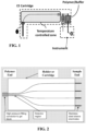
- a capillary assembly, holder, ribbon, cartridge, or the like comprises a capillary array, a cathode, an electrode sleeve, the polymer/buffer source, and polymer introduction mechanism (illustrated as a syringe pump).
- the cathode end of the capillaries may be provided outside the cartridge, for example, so that the cathode capillary ends can move from the sample (for loading of sample to capillary) to buffer (for insertion of the cathode end into the buffer).
- a capillary array is located within a cartridge or holder in accordance with various embodiments of the present invention.
- the figure illustrates, by way of example, a 4-capillary array comprising a capillary array and a holder cartridge.
- the cartridge may include more than four capillaries, for example, 8, 10, 12, 16, or more capillaries, for example, to provide higher throughput or shorter assay runs.
- the cartridge or holder guides the shape of the individual capillaries in the array within the cartridge assembly such that injection ends, and a detector region and a high pressure polymer inlet are formed.
- the capillaries may be spaced closer together over a detector region, for example, to provide efficient more efficient way of providing optical detection during a test, experiment, run, or assay.
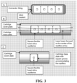
- FIG. 3 depicts a capillary array in accordance with embodiments of the current invention.
- the capillary array comprises a plurality of square capillaries, for example, as plurality of square flexible fused silica capillaries that can be individually fitted with injection-needle.
- the square capillaries may be shaped stainless steel electrodes to perform electro-kinetic sample injection.
- the capillary array may be illuminated by a single beam of light or electromagnetic illumination, for example, provided by a laser beam.
- optical data may be obtained by viewing the capillary array from the top or bottom of the figure.
- the square capillaries may be configured such that deviations in the illuminating beam cross-section as it passes through the square capillaries are less deviations produced by circular capillaries having the same refractive index and fluid contained within the capillaries.
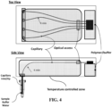
- a cartridge may be provided in accordance with various embodiments to hold the capillary array and to interface with various other elements of a capillary system.
- the cartridge includes the capillary array and a polymer/buffer reservoir, where the polymer serves both as a polymer for the capillaries and an anode buffer.
- the cartridge also includes a single bend in the injection-to-detection region to allow access of the sample inlet/cathode end to sample for loading, capillary cleaner (e.g., water), and buffer for electrophoresis.
- the cartridge may be configured to provide temperature control of at least 80% of the capillary path.
- the cartridge also includes an optical access portion at a location where the capillaries are closer together and near the introduction of the polymer/buffer used during operation of the cartridge and associated system.
- the light source by be a laser, light emitting diode (LED), LED array, xenon or halogen lamp, incandescent light source, or the like.
- the light source is a diode laser, for example, a diode laser having a wavelength of or about 505 nanometers.
- the light source may provide a single wavelength or wavelength range.
- the light source may be configured to provide more than one wavelength or wavelength range, either simultaneously or in a temporally sequential manner.
- the light source may comprise a plurality of light sources having different wavelengths or wavelength ranges, or may comprise a broadband source including one or more optical or dichroic filters.
- Light from the light source may pass through a beam conditioner or beam shaper to provide one or more predetermined optical characteristic including, but not limited to, a beam diameter(s), a beam shape (e.g., circular or elliptical), a predetermined intensity or power profile (e.g., constant, top hat, Gaussian, etc.).
- the beam conditioner may comprise a homogenizer, for example, configured to blend different color light sources and/or to provide a more even illumination cross-section of the output beam.
- the beam shaper is configured to produce or provide a beam that has an elliptical cross section or shape. To produce or provide the elliptical shape, the beam shaper may comprise an anamorphic beam shaper.
- the anamorphic beam shaper may comprise one or more cylindrical lenses configured to produce a beam having an elliptical cross section, that is, in which the beam cross section is wider in one axis than in the other perpendicular axis.
- the beam shaper may comprise a Powel lens, for example, configured to provide a line focus and/or an elliptical beam cross section in which an intensity or power over a cross section of the beam uniform, or nearly uniform.
- the diverging beams from the beam divider in the illustrated embodiment are reflected by a mirror and directed toward the capillary array. Additional mirrors and/or diffractive elements may be included as desired to direct the four beams toward the capillary array, for example, to meet packaging constraints.
- the beams continue to diverge after reflection off the mirror until they are received by the lens L1 shown in FIG. 5 .
- the mirror may be a dichroic mirror, or the like, which may be configured to reflect light at a predetermined wavelength or light over a predetermined wavelength range, while transmitting light or other electromagnetic radiation that is outside the predetermined wavelength or wavelength range.
- the radiation at the image plane is received by spectrometer, which may be configured to separate the signal created by different fluorescent dyes, probes, markers, for example, created by dyes, probes, markers corresponding to the DNA or RNA bases (e.g., adenine, thymine (or uracil), cytosine, and guanine).
- spectrometer may be configured to separate the signal created by different fluorescent dyes, probes, markers, for example, created by dyes, probes, markers corresponding to the DNA or RNA bases (e.g., adenine, thymine (or uracil), cytosine, and guanine).
- the spectrometer may comprise a plurality of fibers, where each fiber may be associated with (e.g., receive radiation from) a corresponding one of the capillaries from the capillary array. Using the fibers, radiation from the capillaries is then transferred into the spectrometer, where it is dispersed by wavelength onto a detector (e.g., an array detector such as a CCD or CMOS detector or the like).
- a detector e.g., an array detector such as a CCD or CMOS detector or the like.
- the plurality of fibers comprises two fiber bundles, FB1 and FB2, each bundle containing a plurality of fibers (two fibers each in the illustrated embodiment).
- the radiation from the fibers of FB1 enters on one side of the spectrometer and radiation from the other fibers in FBs enters on another side of the spectrometer.
- the spectrum from each of the fibers (capillaries) is directed on a different portion of the detector. This configuration has been found to advantageously allow the spectrum from each of multiple capillaries to be produced and detected simultaneously on a single or reduced number of array detectors.
- the emission filter located between lenses L1 and L2 may be configured block or attenuate light from the light source, thereby eliminating or reducing the about of light from the light source that is receive by the spectrometer.
- the focal length of lenses L1 and L2 are selected to produce a magnification of the capillaries or light from the capillaries that is different than one (e.g., to produce a magnified or demagnified image).
- the lens L1 may be selected to have a numerical aperture (NA) that is twice the NA of the lens L2, resulting in a system magnification of two.
- NA numerical aperture
- lens L1 has an NA of 0.4 and lens L2 has an NA of 0.2.
- the focal length or NA of lenses L1, L2 may be selected to (1) provide a focal spot, or focal point, at or near the capillary array that has a predetermined size or diameter and (2) simultaneously providing an NA that is matched to the NA of the spectrometer and/or the NA of the optical fiber system used to transfer light into the spectrometer.
- the entire optical system and cartridge may be located within a common instrument housing.
- the common housing may include an opening or port to allow transfer of radiation or light from the capillary array to the spectrometer.
- the spectrometer may be contained in a separate housing, as shown in FIG. 5 , or included inside the same instrument housing as the optical system.
- the capillary array and/or some of associated hardware may be located outside the instrument housing, in which case an interface with the instrument may be provided via an opening or port in the instrument housing.
- a ribbon configuration of the capillary array is illustrated, which may be used in certain embodiments of the instrument shown in FIG. 5 .
- the ribbon may be configured to interface directly with the instrument or may alternatively be disposed within a carrier or cartridge that interfaces with and/or is coupled to the instrument.
- the ribbon may comprise a V-groove block, fixture, or arrangement that is configured to receive the individual capillaries so as to provide a predetermined alignment and/or spacing between the capillaries of the array.
- a snap feature is shown that may be configured to help maintain the capillaries within the ribbon.
- the V-groove block may also comprise alignment tabs or similar features that are used to engage the instrument in a way that provides a known tolerance in the alignment of the capillaries with the associated light or radiation beams.
- the tabs may be configured to provide a predetermined tolerance of the lateral position of the capillaries relative to the beams and/or a predetermined angular tolerance.
- a capillary array holder or cartridge comprise and dynamic mount that generally constrains or restricts movement in all but one direction.
- the dynamic mount allows movement of the capillary array in a direction perpendicular to length of the individual capillaries, while eliminating or restricting motion in other directions and/or eliminating or restricting angular positioning or motion of the capillary array.
- the dynamic mount advantageously allows a pin of known location relative to the illuminating beams to move the capillary array into a predetermined position relative to the illuminating beams.
- Such a configuration may also be configured to reduce or eliminate twisting of the capillary array during an alignment process.
- alignment of the capillaries and/or capillary array is accomplished using an active alignment.
- a signal from one or more of the capillaries may be used to determine the degree of alignment between the illuminating beams and the capillaries.
- the signal produced during an alignment process or step may be used in conjunction with a movement mechanism that moves one or more of the capillary array, one or more individual capillaries, one or more illumination beams, the capillary cartridge, or some portion of a frame or support located within the instrument housing.
- a series of optical measurements may be made as relative motion is induced between one or more of the capillaries and one or more illuminating beams.
- the degree of alignment may be determined and/or chosen based on a monitoring of the strength of one or more signals produced as the relative position between one or more of the capillaries and one or more of the illumination beams is changed.
- an active alignment process can be accomplished by using a capillary wall scatter signature to find and/or peak a Raman spectrum produced by a medium (e.g., water).
- two or more of the illumination or excitation beams into the different capillaries shown in FIGS. 5-7 are independently produced using separate light or radiation sources for different illumination beams.
- the independently produced illumination or excitation beams into the capillaries may utilize different optical elements for each - for example, separate beam shapers, separate mirror, separate lenses, and the like.
- a common light source may be utilized, but different split into different optical paths that each have their own separate optical and/or conditioning elements.
- each separate illumination or excitation beam may utilize a passive or active process and/or hardware for aligning each beam to its respective capillary - for example, using one or more of the alignment devices or procedures discussed above.
- Such systems and methods advantageously allow greater flexibility in the design and construction of the capillaries and associated cartridge or holder.
- the illumination and imaging optics are located along entirely different paths.
- the system in FIG. 12 comprises two or more capillaries and multiple LEDs or other light sources to produce plural illumination or excitation beams that illuminate corresponding capillaries of the two or more capillaries. Additionally or alternatively, each of the two or more capillaries may have its own spectrometer.
- Such systems advantageously allow greater flexibility in the design and construction of the capillaries and associated cartridge or holder.
Landscapes
- Health & Medical Sciences (AREA)
- Life Sciences & Earth Sciences (AREA)
- Chemical & Material Sciences (AREA)
- Molecular Biology (AREA)
- Pathology (AREA)
- Physics & Mathematics (AREA)
- Analytical Chemistry (AREA)
- Biochemistry (AREA)
- General Health & Medical Sciences (AREA)
- General Physics & Mathematics (AREA)
- Immunology (AREA)
- Electrochemistry (AREA)
- Chemical Kinetics & Catalysis (AREA)
- Dispersion Chemistry (AREA)
- Nuclear Medicine, Radiotherapy & Molecular Imaging (AREA)
- Investigating, Analyzing Materials By Fluorescence Or Luminescence (AREA)
- Investigating Or Analysing Materials By Optical Means (AREA)
Applications Claiming Priority (4)
| Application Number | Priority Date | Filing Date | Title |
|---|---|---|---|
| US201461949914P | 2014-03-07 | 2014-03-07 | |
| US201461949961P | 2014-03-07 | 2014-03-07 | |
| EP15712217.7A EP3114469B1 (de) | 2014-03-07 | 2015-03-06 | Optisches system für kapillarelektrophorese |
| PCT/US2015/019280 WO2015134925A1 (en) | 2014-03-07 | 2015-03-06 | Optical system for capillary electrophoresis |
Related Parent Applications (1)
| Application Number | Title | Priority Date | Filing Date |
|---|---|---|---|
| EP15712217.7A Division EP3114469B1 (de) | 2014-03-07 | 2015-03-06 | Optisches system für kapillarelektrophorese |
Publications (2)
| Publication Number | Publication Date |
|---|---|
| EP4517318A2 true EP4517318A2 (de) | 2025-03-05 |
| EP4517318A3 EP4517318A3 (de) | 2025-03-26 |
Family
ID=52737400
Family Applications (2)
| Application Number | Title | Priority Date | Filing Date |
|---|---|---|---|
| EP24213815.4A Pending EP4517318A3 (de) | 2014-03-07 | 2015-03-06 | Optisches system für kapillarelektrophorese |
| EP15712217.7A Active EP3114469B1 (de) | 2014-03-07 | 2015-03-06 | Optisches system für kapillarelektrophorese |
Family Applications After (1)
| Application Number | Title | Priority Date | Filing Date |
|---|---|---|---|
| EP15712217.7A Active EP3114469B1 (de) | 2014-03-07 | 2015-03-06 | Optisches system für kapillarelektrophorese |
Country Status (5)
| Country | Link |
|---|---|
| US (2) | US11280759B2 (de) |
| EP (2) | EP4517318A3 (de) |
| JP (1) | JP6755188B2 (de) |
| CN (2) | CN115389599B (de) |
| WO (1) | WO2015134925A1 (de) |
Families Citing this family (18)
| Publication number | Priority date | Publication date | Assignee | Title |
|---|---|---|---|---|
| CN115389599B (zh) * | 2014-03-07 | 2025-10-28 | 生命技术公司 | 用于毛细管电泳的光学系统 |
| WO2015179098A1 (en) | 2014-05-21 | 2015-11-26 | Integenx Inc. | Fluidic cartridge with valve mechanism |
| CN107106983B (zh) | 2014-10-22 | 2021-04-16 | 尹特根埃克斯有限公司 | 用于样品制备、处理和分析的系统和方法 |
| CN105548325B (zh) * | 2016-01-30 | 2018-01-12 | 福州大学 | 毛细管电泳转轴式液滴进样装置及其进样方法 |
| CN105973860B (zh) * | 2016-06-29 | 2019-07-30 | 山东科立森生物股份有限公司 | 一种毛细管电泳检测系统及检测方法 |
| CN105973859B (zh) * | 2016-06-29 | 2019-01-29 | 山东科立森生物股份有限公司 | 一种毛细管电泳检测系统及检测方法 |
| SG11201900782UA (en) | 2016-08-15 | 2019-02-27 | Univ Tasmania | Inorganic ion detection system and methods |
| WO2018156969A1 (en) * | 2017-02-24 | 2018-08-30 | Life Technologies Corporation | Optical systems and methods for sample separation |
| SG11201908837UA (en) * | 2017-02-24 | 2019-10-30 | Life Technologies Corp | Capillary electrophoresis systems, related devices, and related methods |
| JP6685965B2 (ja) | 2017-03-29 | 2020-04-22 | 株式会社日立ハイテク | キャピラリ電気泳動装置および恒温槽 |
| US10302295B2 (en) * | 2017-10-18 | 2019-05-28 | Rite-Hite Holding Corporation | Illuminating fans for loading docks |
| US11222779B2 (en) * | 2018-05-17 | 2022-01-11 | GMJ Technologies, Inc. | Apparatuses for optical and mass spectrometry detection |
| US11747300B2 (en) * | 2018-09-03 | 2023-09-05 | Hitachi High-Tech Corporation | Capillary array unit |
| WO2020190969A1 (en) * | 2019-03-18 | 2020-09-24 | Life Technologies Corporation | Multi-capillary optical detection system |
| US12209954B2 (en) | 2019-08-07 | 2025-01-28 | Life Technologies Corporation | Multi-capillary optical detection system |
| JP7364798B2 (ja) * | 2020-07-31 | 2023-10-18 | 株式会社日立ハイテク | キャピラリ電気泳動装置 |
| WO2022153571A1 (ja) * | 2021-01-15 | 2022-07-21 | エースバイオアナリシス株式会社 | 走査ユニット、システムおよび方法、ならびにマイクロカラム |
| US11733156B2 (en) * | 2021-02-23 | 2023-08-22 | Joseph R. Demers | Semiconductor package for free-space coupling of radiation and method |
Family Cites Families (35)
| Publication number | Priority date | Publication date | Assignee | Title |
|---|---|---|---|---|
| JP3563140B2 (ja) * | 1995-01-19 | 2004-09-08 | 株式会社日立製作所 | キャピラリーアレイ電気泳動装置 |
| US5439578A (en) * | 1993-06-03 | 1995-08-08 | The Governors Of The University Of Alberta | Multiple capillary biochemical analyzer |
| US5614726A (en) | 1995-03-23 | 1997-03-25 | Beckman Instruments, Inc. | Automated optical alignment system and method using Raman scattering of capillary tube contents |
| US6017434A (en) | 1995-05-09 | 2000-01-25 | Curagen Corporation | Apparatus and method for the generation, separation, detection, and recognition of biopolymer fragments |
| US6361672B1 (en) * | 1996-06-10 | 2002-03-26 | Transgenomic, Inc. | Multiple laser diode electromagnetic radiation source in multiple electrophoresis channel systems |
| US6084667A (en) * | 1997-03-12 | 2000-07-04 | Nz Applied Technologies | System and method for molecular sample measurement |
| FR2774472B1 (fr) * | 1998-01-30 | 2000-04-21 | Centre Nat Rech Scient | Perfectionnements aux systemes d'electrophorese multicapillaire |
| JP2002540401A (ja) | 1999-03-19 | 2002-11-26 | ザ ガヴァナーズ オブ ザ ユニヴァーシティー オブ アルバータ | 生物学的及びその他の試料の自動化2次元分析 |
| US20050279949A1 (en) | 1999-05-17 | 2005-12-22 | Applera Corporation | Temperature control for light-emitting diode stabilization |
| US6156178A (en) * | 1999-07-13 | 2000-12-05 | Molecular Dynamics, Inc. | Increased throughput analysis of small compounds using multiple temporally spaced injections |
| JP3896739B2 (ja) * | 1999-10-29 | 2007-03-22 | 株式会社日立製作所 | キャピラリー電気泳動装置 |
| US6690467B1 (en) * | 2000-05-05 | 2004-02-10 | Pe Corporation | Optical system and method for optically analyzing light from a sample |
| JP4103302B2 (ja) * | 2000-05-15 | 2008-06-18 | 株式会社日立製作所 | キャピラリアレイを用いた電気泳動装置及びそれに用いられるサンプルプレートアセンブリ |
| WO2001090726A2 (en) * | 2000-05-19 | 2001-11-29 | Aclara Biosciences, Inc. | Optical alignment in capillary detection using capillary wall scatter |
| JP2002228586A (ja) | 2001-01-31 | 2002-08-14 | Hitachi Ltd | 蛍光測定装置及び蛍光測定方法 |
| FR2827957B1 (fr) * | 2001-07-25 | 2003-09-26 | Picometrics | Appareil de separation par electrophorese sur veine liquide et de detection par fluorescence induite par laser |
| US6870165B2 (en) * | 2001-10-19 | 2005-03-22 | Biocal Technology, Inc. | Multi-color multiplexed analysis in a bio-separation system |
| US7189361B2 (en) * | 2001-12-19 | 2007-03-13 | 3M Innovative Properties Company | Analytical device with lightguide Illumination of capillary and microgrooves arrays |
| JP3562514B2 (ja) * | 2002-02-08 | 2004-09-08 | 株式会社日立製作所 | キャピラリーアレイ |
| US7419578B2 (en) | 2003-04-11 | 2008-09-02 | Hitachi High-Technologies Corporation | Capillary electrophoresis apparatus |
| JP4431421B2 (ja) | 2003-04-11 | 2010-03-17 | 株式会社日立ハイテクノロジーズ | キャピラリー電気泳動装置 |
| US7298478B2 (en) * | 2003-08-14 | 2007-11-20 | Cytonome, Inc. | Optical detector for a particle sorting system |
| US20060176481A1 (en) * | 2005-02-10 | 2006-08-10 | Massachusetts Institute Of Technology | End-column fluorescence detection for capillary array electrophoresis |
| JP4616051B2 (ja) * | 2005-04-05 | 2011-01-19 | 株式会社日立ハイテクノロジーズ | 電気泳動装置、及び電気泳動方法 |
| US7692783B2 (en) | 2006-02-13 | 2010-04-06 | Pacific Biosciences Of California | Methods and systems for simultaneous real-time monitoring of optical signals from multiple sources |
| CN101013083A (zh) * | 2007-02-01 | 2007-08-08 | 大连理工大学 | 光纤嵌入式低电压驱动毛细管电泳芯片 |
| CN101105455A (zh) * | 2007-07-04 | 2008-01-16 | 四川大学 | 激光诱导荧光检测器 |
| JP2009080070A (ja) * | 2007-09-27 | 2009-04-16 | Panasonic Corp | 生体物質検出装置 |
| US8975572B2 (en) * | 2008-04-04 | 2015-03-10 | Cvi Laser, Llc | Compact, thermally stable fiber-optic array mountable to flow cell |
| JP2010078559A (ja) | 2008-09-29 | 2010-04-08 | Sumitomo Electric Ind Ltd | 蛍光分析装置および方法 |
| WO2010111231A1 (en) * | 2009-03-23 | 2010-09-30 | Raindance Technologies, Inc. | Manipulation of microfluidic droplets |
| US8357281B2 (en) * | 2009-09-21 | 2013-01-22 | Advanced Analytical Technologies, Inc. | Multi-wavelength fluorescence detection system for multiplexed capillary electrophoresis |
| CN102023146A (zh) * | 2010-09-28 | 2011-04-20 | 上海理工大学 | 一种光学检测的电泳芯片及其电泳装置 |
| US20140049771A1 (en) * | 2012-08-16 | 2014-02-20 | Behrokh B. Sadri | High-throughput multi laser wave mixing detection methods and apparatus |
| CN115389599B (zh) * | 2014-03-07 | 2025-10-28 | 生命技术公司 | 用于毛细管电泳的光学系统 |
-
2015
- 2015-03-06 CN CN202211196912.1A patent/CN115389599B/zh active Active
- 2015-03-06 EP EP24213815.4A patent/EP4517318A3/de active Pending
- 2015-03-06 CN CN201580017012.8A patent/CN106164665A/zh active Pending
- 2015-03-06 WO PCT/US2015/019280 patent/WO2015134925A1/en not_active Ceased
- 2015-03-06 US US15/124,013 patent/US11280759B2/en active Active
- 2015-03-06 EP EP15712217.7A patent/EP3114469B1/de active Active
- 2015-03-06 JP JP2016573713A patent/JP6755188B2/ja active Active
-
2022
- 2022-02-23 US US17/678,590 patent/US20220244218A1/en not_active Abandoned
Also Published As
| Publication number | Publication date |
|---|---|
| US20170016853A1 (en) | 2017-01-19 |
| EP3114469B1 (de) | 2024-11-20 |
| EP3114469A1 (de) | 2017-01-11 |
| CN115389599B (zh) | 2025-10-28 |
| US11280759B2 (en) | 2022-03-22 |
| CN115389599A (zh) | 2022-11-25 |
| JP6755188B2 (ja) | 2020-09-16 |
| CN106164665A (zh) | 2016-11-23 |
| JP2017507342A (ja) | 2017-03-16 |
| WO2015134925A1 (en) | 2015-09-11 |
| EP4517318A3 (de) | 2025-03-26 |
| US20220244218A1 (en) | 2022-08-04 |
Similar Documents
| Publication | Publication Date | Title |
|---|---|---|
| US20220244218A1 (en) | Optical system for capillary electrophoresis | |
| US11860122B2 (en) | Optical systems and methods for sample separation | |
| JP6423527B2 (ja) | 光学ホモジナイザ | |
| US20100220315A1 (en) | Stabilized Optical System for Flow Cytometry | |
| US10753873B2 (en) | Multicolor detection device | |
| EP2843392B1 (de) | Vorrichtung zur fotometrischen messung von biologischen flüssigkeiten | |
| CN109844449A (zh) | 用于流式细胞仪的紧凑检测模块 | |
| EP2693252B1 (de) | Array-Optik | |
| US7221449B2 (en) | Apparatus for assaying fluorophores in a biological sample | |
| CN107576639A (zh) | 便携式全集成dna现场检验微型全分析系统检测光路 | |
| WO2023077306A1 (zh) | 检测设备、基因测序系统及检测方法 | |
| CN113899677A (zh) | 用于流式细胞仪检测的反射式分光模块及分光方法 | |
| KR20130083259A (ko) | 레이저 유발 형광을 이용한 모세관 전기영동을 위한 다채널 형광 검출기 |
Legal Events
| Date | Code | Title | Description |
|---|---|---|---|
| PUAI | Public reference made under article 153(3) epc to a published international application that has entered the european phase |
Free format text: ORIGINAL CODE: 0009012 |
|
| STAA | Information on the status of an ep patent application or granted ep patent |
Free format text: STATUS: THE APPLICATION HAS BEEN PUBLISHED |
|
| PUAL | Search report despatched |
Free format text: ORIGINAL CODE: 0009013 |
|
| AC | Divisional application: reference to earlier application |
Ref document number: 3114469 Country of ref document: EP Kind code of ref document: P |
|
| AK | Designated contracting states |
Kind code of ref document: A2 Designated state(s): AL AT BE BG CH CY CZ DE DK EE ES FI FR GB GR HR HU IE IS IT LI LT LU LV MC MK MT NL NO PL PT RO RS SE SI SK SM TR |
|
| AK | Designated contracting states |
Kind code of ref document: A3 Designated state(s): AL AT BE BG CH CY CZ DE DK EE ES FI FR GB GR HR HU IE IS IT LI LT LU LV MC MK MT NL NO PL PT RO RS SE SI SK SM TR |
|
| RIC1 | Information provided on ipc code assigned before grant |
Ipc: G01N 27/447 20060101AFI20250219BHEP |
|
| STAA | Information on the status of an ep patent application or granted ep patent |
Free format text: STATUS: REQUEST FOR EXAMINATION WAS MADE |
|
| STAA | Information on the status of an ep patent application or granted ep patent |
Free format text: STATUS: EXAMINATION IS IN PROGRESS |
|
| 17P | Request for examination filed |
Effective date: 20250911 |
|
| 17Q | First examination report despatched |
Effective date: 20251008 |