EP4517203A1 - Building chiller/heat pump system carbon emission reduction by shifting temperature setpoint - Google Patents
Building chiller/heat pump system carbon emission reduction by shifting temperature setpoint Download PDFInfo
- Publication number
- EP4517203A1 EP4517203A1 EP24197071.4A EP24197071A EP4517203A1 EP 4517203 A1 EP4517203 A1 EP 4517203A1 EP 24197071 A EP24197071 A EP 24197071A EP 4517203 A1 EP4517203 A1 EP 4517203A1
- Authority
- EP
- European Patent Office
- Prior art keywords
- setpoint
- chiller
- heat pump
- pump system
- building
- Prior art date
- Legal status (The legal status is an assumption and is not a legal conclusion. Google has not performed a legal analysis and makes no representation as to the accuracy of the status listed.)
- Pending
Links
Images


Classifications
-
- F—MECHANICAL ENGINEERING; LIGHTING; HEATING; WEAPONS; BLASTING
- F24—HEATING; RANGES; VENTILATING
- F24F—AIR-CONDITIONING; AIR-HUMIDIFICATION; VENTILATION; USE OF AIR CURRENTS FOR SCREENING
- F24F11/00—Control or safety arrangements
- F24F11/70—Control systems characterised by their outputs; Constructional details thereof
- F24F11/80—Control systems characterised by their outputs; Constructional details thereof for controlling the temperature of the supplied air
-
- F—MECHANICAL ENGINEERING; LIGHTING; HEATING; WEAPONS; BLASTING
- F24—HEATING; RANGES; VENTILATING
- F24F—AIR-CONDITIONING; AIR-HUMIDIFICATION; VENTILATION; USE OF AIR CURRENTS FOR SCREENING
- F24F11/00—Control or safety arrangements
- F24F11/62—Control or safety arrangements characterised by the type of control or by internal processing, e.g. using fuzzy logic, adaptive control or estimation of values
- F24F11/63—Electronic processing
- F24F11/64—Electronic processing using pre-stored data
-
- F—MECHANICAL ENGINEERING; LIGHTING; HEATING; WEAPONS; BLASTING
- F24—HEATING; RANGES; VENTILATING
- F24F—AIR-CONDITIONING; AIR-HUMIDIFICATION; VENTILATION; USE OF AIR CURRENTS FOR SCREENING
- F24F11/00—Control or safety arrangements
- F24F11/30—Control or safety arrangements for purposes related to the operation of the system, e.g. for safety or monitoring
- F24F11/46—Improving electric energy efficiency or saving
-
- F—MECHANICAL ENGINEERING; LIGHTING; HEATING; WEAPONS; BLASTING
- F24—HEATING; RANGES; VENTILATING
- F24F—AIR-CONDITIONING; AIR-HUMIDIFICATION; VENTILATION; USE OF AIR CURRENTS FOR SCREENING
- F24F11/00—Control or safety arrangements
- F24F11/30—Control or safety arrangements for purposes related to the operation of the system, e.g. for safety or monitoring
- F24F11/46—Improving electric energy efficiency or saving
- F24F11/47—Responding to energy costs
-
- F—MECHANICAL ENGINEERING; LIGHTING; HEATING; WEAPONS; BLASTING
- F24—HEATING; RANGES; VENTILATING
- F24F—AIR-CONDITIONING; AIR-HUMIDIFICATION; VENTILATION; USE OF AIR CURRENTS FOR SCREENING
- F24F11/00—Control or safety arrangements
- F24F11/50—Control or safety arrangements characterised by user interfaces or communication
- F24F11/61—Control or safety arrangements characterised by user interfaces or communication using timers
-
- F—MECHANICAL ENGINEERING; LIGHTING; HEATING; WEAPONS; BLASTING
- F24—HEATING; RANGES; VENTILATING
- F24F—AIR-CONDITIONING; AIR-HUMIDIFICATION; VENTILATION; USE OF AIR CURRENTS FOR SCREENING
- F24F11/00—Control or safety arrangements
- F24F11/62—Control or safety arrangements characterised by the type of control or by internal processing, e.g. using fuzzy logic, adaptive control or estimation of values
- F24F11/63—Electronic processing
-
- F—MECHANICAL ENGINEERING; LIGHTING; HEATING; WEAPONS; BLASTING
- F24—HEATING; RANGES; VENTILATING
- F24F—AIR-CONDITIONING; AIR-HUMIDIFICATION; VENTILATION; USE OF AIR CURRENTS FOR SCREENING
- F24F11/00—Control or safety arrangements
- F24F11/62—Control or safety arrangements characterised by the type of control or by internal processing, e.g. using fuzzy logic, adaptive control or estimation of values
- F24F11/63—Electronic processing
- F24F11/65—Electronic processing for selecting an operating mode
- F24F11/67—Switching between heating and cooling modes
-
- F—MECHANICAL ENGINEERING; LIGHTING; HEATING; WEAPONS; BLASTING
- F24—HEATING; RANGES; VENTILATING
- F24F—AIR-CONDITIONING; AIR-HUMIDIFICATION; VENTILATION; USE OF AIR CURRENTS FOR SCREENING
- F24F2140/00—Control inputs relating to system states
- F24F2140/60—Energy consumption
Definitions
- This application relates to a method and control which is operable to change a building chiller/heat pump system temperature setpoint based upon the relative "dirty/clean" nature of available electricity. Dirty or clean refers to the emissions associated to the production of such electricity, including the levels of carbon dioxide release or other contaminants.
- chiller/heat pump system is operable to cool environmental air in hot times and provide heat during colder times.
- One such system is a so-called chiller or heat pump.
- water is either heated or cooled by a refrigerant cycle, and supplied through radiators to heat or cool the air in a building.
- New built buildings can be provided with more energy efficient chiller/heat pump systems. However, it would be unduly expensive to modify existing chiller/heat pump systems in a similar manner.
- a building chiller/heat pump system comprising one or multiple chillers/heat pumps for supplying a conditioned fluid to change a temperature of air being delivered into a building.
- the chiller/heat pump system is provided with a control to achieve the desired setpoint of the air delivered into the building.
- the control is programmed to receive a prediction of power grid electricity expected to be generated and the emission levels embedded in that electricity that will be delivered to power the chiller/heat pump system.
- the control is programmed to change the water temperature setpoint such that an energy level required to operate the chiller/heat pump system to achieve this setpoint will drop when the expected emissions level increases, and adjusts this setpoint in an opposed direction when the expected emissions drops, while the level of temperature comfort in the conditioned building or zone is maintained within a predefined margin.
- the water temperature setpoint is increased for a period of time, and if the chiller/heat pump is operating in a heating mode, the setpoint is decreased for a period of time.
- the water temperature water temperature setpoint is changed in the opposed direction, it is changed to a magnitude that exceeds the actual desired setpoint at that time.
- the prediction is a prediction of quantity of emissions per a unit of energy.
- the chiller/heat pump system is one or multiple water chiller or heat pump plant system, and the controls change a temperature of the water leaving the chiller or heat pump to achieve a desired temperature within the building.
- the change in the water temperature setpoint occurs across a plurality of cycles during an extended period of relatively dirty power supply.
- the water temperature setpoint is changed in the opposed direction, it is changed to a magnitude that exceeds the actual desired setpoint at that time.
- the prediction is a prediction of quantum of emissions utilized by the system to deliver acceptable levels of comfort.
- the chiller/heat pump system is a water chiller, and the control changes a temperature of the water to achieve the desired setpoint of air delivered into the building.
- the change in the water temperature setpoint occurs across a plurality of cycles during an extended period of relatively dirty power supply.
- a method of operating a chiller/heat pump system for suppling a conditioned fluid to change a temperature of air being delivered into the building is provided with a control to achieve a desired setpoint of the air delivered into the building.
- the control receives a prediction of expected emissions levels in energy that will be delivered to power the chiller/heat pump system.
- the control changes the water temperature setpoint such that an energy level required to operate the chiller/heat pump system to achieve the setpoint will drop when the emissions level increases, and adjusts the setpoint in an opposed direction when the expected emissions level drops.
- the water temperature setpoint is increased for a period of time, and if the chiller/heat pump is operating in a heating mode, the setpoint is decreased for a period of time.
- the water temperature setpoint is changed in the opposed direction, it is changed to a magnitude that exceeds the actual desired setpoint at that time.
- the prediction is a prediction of quantum of emissions per a unit of energy.
- the chiller/heat pump system is a water chiller, and the control changing a temperature of the water to achieve a desired temperature of air delivered into the building.
- the water temperature setpoint is changed in the opposed direction, it is changed to a magnitude that exceeds the actual desired setpoint at that time.
- the prediction is a prediction of quantum of emissions per a unit of energy.
- the chiller/heat pump system is a water chiller, and the control changes a temperature of the water to achieve the desired temperature delivered into the building.
- the change in the water temperature setpoint occurs across a plurality of cycles during an extended period of relatively dirty power supply.
- FIG. 1 schematically shows a building chiller/heat pump system 20.
- a building 21 is shown schematically receiving system 20.
- System 20 has a heat exchanger 22 through which water passes to exchange heat with air at 24 to be delivered into the building 21.
- the chiller/heat pump system 20 is a water chiller, and water is a working fluid in the heat exchanger 22.
- the chiller/heat pump system 20 is operating in a cooling mode, the water passing through heat exchanger 22 is relative cool and it cools the air delivered at 24 into the building 21. Alternatively, during heating operation the water delivered into the heat exchanger 22 is relatively hot.
- the detail of the water chiller and its operation in heating and cooling modes may be as known and forms no portion of this disclosure.
- a second heat exchanger 26 is associated with a refrigerant system 27 to either heat or cool the water prior to being delivered to exchange heat with the air at element 24.
- the refrigerant system 27 includes a compressor 28, the heat exchanger 26, an expansion device 30 and a second heat exchanger 32.
- a fluid line 34 selectively delivers a fluid to either heat or cool the refrigerant in heat exchanger 32.
- a control 19 is shown schematically, and controls the refrigerant system in a manner such that the temperature of the water delivered to heat exchanger 22 is at a desired "setpoint" for the air being delivered through the element 24 into the building 21.
- FIG. 2 shows an example of what an MOER might look like. A graph of the quantum of emissions over time is shown. It is known that during a day, and across seasons, an electricity supply system will rely on fossil fuel (“dirty”) for a certain percentage and more renewable or green sources (“clean”) as available. As an example, wind, nuclear or solar power are used to supplement fossil fuel.
- dirty fossil fuel
- clean renewable or green sources
- the percentage of "clean" power varies with the availability of, say, wind, nuclear and solar energy.
- the quantum at point X midnight
- that value at Y may have fallen.
- point Z the value may have again increased.
- the chart varies with time, season, etc., and further with the weather of a particular day. That is, as shown at I, it is not always variable simply by the hour of the day.
- the present invention includes control 19 being programmed to respond to the predicted high emissions level, and adjust a set point of the air being delivered into the building 21.
- the control 19 is provided with information such as shown in Figure 2 predicting the emissions overtime.
- the MOER at 40 is shown having a "dirty" increasing spike at 42.
- a cooling water temperature setpoint 48 is increased at 49 to reduce the volume use of the dirty energy.
- the cooling water temperature setpoint is controlled to drop lower at 50 to help the temperature within the building recover.
- the setpoint is initially changed in the opposed direction, it may change to a magnitude that exceeds the actual desired setpoint at that time.
- the cooling water temperature setpoint then increases at 51 back to the actual desired level once the MOER returns to its normal number 43.
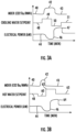
- Figure 3A shows the system 20 operating in a cooling mode. It is also shown that the renewable electric power line 44 would include a drop at 46 to coincide with the spike 42.
- Figure 3B shows how the control 19 is programmed to control the chiller/heat pump system 20 when operating in a heating mode.
- the water temperature setpoint 48 drops at 60 when the spike 42 occurs, and increases at 62 when the MOER returns to its normal level at 43, or when the building temperature becomes unacceptable. Increase 62 allows the building temperature to quickly recover.
- the setpoint then moves down from point 62 to the actual desired setpoint 63 after a period of time.
- the electrical power 44 has a drop 46 consistent with the spike 42 and then an increase 64.
- Figure 3C shows one other control mode.
- the MOER 40 has a long spike 42.
- the water temperature setpoint line 48 then increases at 149 for a period of time before dropping at 150, and then cyclically moving between 149 and 150 until returning to a desired level at 151.
- Figure 3C shows operation in a cooling mode but the same could occur in a heating mode.
- FIG. 4 is a flowchart for the disclosed method.
- a chiller is operated.
- clean and dirty energy times are identified such as from a MOER.
- a temperature setpoint is adjusted based upon the relative clean and dirty energy over time.
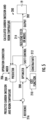
- Figure 5 is a block diagram 200 of a model predictive control.
- An output 202 goes to the control 90 for the chiller/heat pump system.
- a predictor 204 receives the MOER information at 206. The predictor also receives the output, and is able to calculate carbon emission and the actual room temperature that will be experienced in the building.
- An input 216 may be a reference temperature such as from the building.
- An optimizer 208 is programmed to make the decisions and operate the method as disclosed above.
- Optimizer 208 is provided with cost function information 210 and constraints at 212.
- the constraints may be, as an example, a limit on how far out of the target temperature the control may move the temperature away from a desired temperature and limits for how long.
- a building field or model 214 is also provided.
- the model predictive control 200 is operable to calculate a carbon emissions savings based upon the method and apparatus of this invention.
- the predicted emissions per BTU of energy can be utilized in combination with the reduction in BTUs over the period of time for each reduction to reach a quantum of carbon emissions saved by this method. Such savings can then be reported to various organizations that credit carbon emission savings. While the basic algorithm for calculating carbon emission saving is mentioned above, more refined algorithms may be developed.
- chiller While a chiller is specifically disclosed it should be understood that the same basic concept could extend to other types of chiller/heat pump system including standard air conditioning systems, as an example.
Landscapes
- Engineering & Computer Science (AREA)
- Chemical & Material Sciences (AREA)
- Combustion & Propulsion (AREA)
- Mechanical Engineering (AREA)
- General Engineering & Computer Science (AREA)
- Signal Processing (AREA)
- Physics & Mathematics (AREA)
- Fuzzy Systems (AREA)
- Mathematical Physics (AREA)
- Human Computer Interaction (AREA)
- Air Conditioning Control Device (AREA)
Abstract
A building chiller/heat pump system (20) includes a chiller/heat pump system (20) for supplying a conditioned fluid to change a temperature of air being delivered into a building (21). The chiller/heat pump system (20) is provided with a control (19) to achieve a desired setpoint of the air delivered into the building (19). The control (19) is programmed to receive a prediction of expected remission levels in energy that will be delivered to power the chiller/heat pump system (20). The control (19) is programmed to change the setpoint such that an energy level required to operate the chiller/heat pump system (20) to achieve the setpoint will drop when the expected emissions level increases, and adjusts the setpoint in an opposed direction when the expected emissions drops. A method is also disclosed.
Description
- This application relates to a method and control which is operable to change a building chiller/heat pump system temperature setpoint based upon the relative "dirty/clean" nature of available electricity. Dirty or clean refers to the emissions associated to the production of such electricity, including the levels of carbon dioxide release or other contaminants.
- Most modern buildings are provided with a chiller/heat pump system. The chiller/heat pump system is operable to cool environmental air in hot times and provide heat during colder times. One such system is a so-called chiller or heat pump. In a chiller/heat pump system, water is either heated or cooled by a refrigerant cycle, and supplied through radiators to heat or cool the air in a building.
- Currently, carbon emissions from buildings accounts for approximately 33% of world annual carbon emissions. In a typical commercial building, the chiller/heat pump system accounts for 30-50% of that total.
- New built buildings can be provided with more energy efficient chiller/heat pump systems. However, it would be unduly expensive to modify existing chiller/heat pump systems in a similar manner.
- According to a first aspect of the invention there is provided a building chiller/heat pump system comprising one or multiple chillers/heat pumps for supplying a conditioned fluid to change a temperature of air being delivered into a building. The chiller/heat pump system is provided with a control to achieve the desired setpoint of the air delivered into the building. The control is programmed to receive a prediction of power grid electricity expected to be generated and the emission levels embedded in that electricity that will be delivered to power the chiller/heat pump system. The control is programmed to change the water temperature setpoint such that an energy level required to operate the chiller/heat pump system to achieve this setpoint will drop when the expected emissions level increases, and adjusts this setpoint in an opposed direction when the expected emissions drops, while the level of temperature comfort in the conditioned building or zone is maintained within a predefined margin.
- Optionally when the available energy is relatively dirty, and the chiller/heat pump system is operating in a cooling mode, the water temperature setpoint is increased for a period of time, and if the chiller/heat pump is operating in a heating mode, the setpoint is decreased for a period of time.
- Optionally when the water temperature water temperature setpoint is changed in the opposed direction, it is changed to a magnitude that exceeds the actual desired setpoint at that time.
- Optionally the prediction is a prediction of quantity of emissions per a unit of energy.
- Optionally the chiller/heat pump system is one or multiple water chiller or heat pump plant system, and the controls change a temperature of the water leaving the chiller or heat pump to achieve a desired temperature within the building.
- Optionally the change in the water temperature setpoint occurs across a plurality of cycles during an extended period of relatively dirty power supply.
- Optionally when the water temperature setpoint is changed in the opposed direction, it is changed to a magnitude that exceeds the actual desired setpoint at that time.
- Optionally the prediction is a prediction of quantum of emissions utilized by the system to deliver acceptable levels of comfort.
- Optionally the chiller/heat pump system is a water chiller, and the control changes a temperature of the water to achieve the desired setpoint of air delivered into the building.
- Optionally the change in the water temperature setpoint occurs across a plurality of cycles during an extended period of relatively dirty power supply.
- According to a second aspect of the invention there is provided a method of operating a chiller/heat pump system for suppling a conditioned fluid to change a temperature of air being delivered into the building. The chiller/heat pump system is provided with a control to achieve a desired setpoint of the air delivered into the building. The control receives a prediction of expected emissions levels in energy that will be delivered to power the chiller/heat pump system. The control changes the water temperature setpoint such that an energy level required to operate the chiller/heat pump system to achieve the setpoint will drop when the emissions level increases, and adjusts the setpoint in an opposed direction when the expected emissions level drops.
- Optionally when available energy is dirty, and the chiller/heat pump system is operating in a cooling mode, the water temperature setpoint is increased for a period of time, and if the chiller/heat pump is operating in a heating mode, the setpoint is decreased for a period of time.
- Optionally when the water temperature setpoint is changed in the opposed direction, it is changed to a magnitude that exceeds the actual desired setpoint at that time.
- Optionally the prediction is a prediction of quantum of emissions per a unit of energy.
- Optionally the chiller/heat pump system is a water chiller, and the control changing a temperature of the water to achieve a desired temperature of air delivered into the building.
- Optionally the change in the water temperature setpoint occurs across a plurality of cycles during an extended period of relatively dirty power supply.
- Optionally when the water temperature setpoint is changed in the opposed direction, it is changed to a magnitude that exceeds the actual desired setpoint at that time.
- Optionally the prediction is a prediction of quantum of emissions per a unit of energy.
- Optionally the chiller/heat pump system is a water chiller, and the control changes a temperature of the water to achieve the desired temperature delivered into the building.
- Optionally the change in the water temperature setpoint occurs across a plurality of cycles during an extended period of relatively dirty power supply.
- The various features and advantages of certain exemplary embodiments will be described in greater detail by way of example only. The drawings that accompany the detailed description can be briefly described as follows.
-
-
Figure 1 schematically shows a chiller/heat pump system. -
Figure 2 shows a projection of a marginal operating emissions rate. -
Figure 3A shows a control using an energy projection rate. -
Figure 3B shows a similar condition when the chiller/heat pump system is operating in a heating mode. -
Figure 3C shows another condition during a cooling mode. -
Figure 4 shows a flowchart. -
Figure 5 shows a block diagram of a model predictive control. -
Figure 1 schematically shows a building chiller/heat pump system 20. Abuilding 21 is shown schematically receivingsystem 20. Of course, as known, much ofsystem 20 may actually be outside thebuilding 21.System 20 has aheat exchanger 22 through which water passes to exchange heat with air at 24 to be delivered into thebuilding 21. In a disclosed embodiment the chiller/heat pump system 20 is a water chiller, and water is a working fluid in theheat exchanger 22. - If the chiller/
heat pump system 20 is operating in a cooling mode, the water passing throughheat exchanger 22 is relative cool and it cools the air delivered at 24 into thebuilding 21. Alternatively, during heating operation the water delivered into theheat exchanger 22 is relatively hot. The detail of the water chiller and its operation in heating and cooling modes may be as known and forms no portion of this disclosure. - A
second heat exchanger 26 is associated with arefrigerant system 27 to either heat or cool the water prior to being delivered to exchange heat with the air atelement 24. Therefrigerant system 27 includes acompressor 28, theheat exchanger 26, an expansion device 30 and asecond heat exchanger 32. Afluid line 34 selectively delivers a fluid to either heat or cool the refrigerant inheat exchanger 32. Acontrol 19 is shown schematically, and controls the refrigerant system in a manner such that the temperature of the water delivered toheat exchanger 22 is at a desired "setpoint" for the air being delivered through theelement 24 into thebuilding 21. - Again, the operation of such systems is as known.
- Recently, third party data suppliers are providing information known as a marginal operating emission rate ("MOER").
Figure 2 shows an example of what an MOER might look like. A graph of the quantum of emissions over time is shown. It is known that during a day, and across seasons, an electricity supply system will rely on fossil fuel ("dirty") for a certain percentage and more renewable or green sources ("clean") as available. As an example, wind, nuclear or solar power are used to supplement fossil fuel. - However, the percentage of "clean" power varies with the availability of, say, wind, nuclear and solar energy. As such, as shown at
Figure 2 , the quantum at point X, midnight, may be relatively high. By noon the next day, that value at Y may have fallen. By point Z the value may have again increased. - As shown at I, the chart varies with time, season, etc., and further with the weather of a particular day. That is, as shown at I, it is not always variable simply by the hour of the day.
- The present invention includes
control 19 being programmed to respond to the predicted high emissions level, and adjust a set point of the air being delivered into thebuilding 21. Thecontrol 19 is provided with information such as shown inFigure 2 predicting the emissions overtime. - Now, as shown in
Figure 3A , the MOER at 40 is shown having a "dirty" increasing spike at 42. A coolingwater temperature setpoint 48 is increased at 49 to reduce the volume use of the dirty energy. Aspoint 42 passes, the cooling water temperature setpoint is controlled to drop lower at 50 to help the temperature within the building recover. When the setpoint is initially changed in the opposed direction, it may change to a magnitude that exceeds the actual desired setpoint at that time. The cooling water temperature setpoint then increases at 51 back to the actual desired level once the MOER returns to itsnormal number 43. - By doing this, the overall carbon emission from the chiller/
heat pump system 20 is reduced. The reduction may not be enormous, but over time even small reductions are valuable. - It should be understood that there is a good deal of thermal inertia in a chiller/heat pump system such as
system 20, and thus even though the water temperature setpoint is increased at 49, the air would not necessarily immediately become unduly warm. Also, the increase need not be large. - It should be understood that
Figure 3A shows thesystem 20 operating in a cooling mode. It is also shown that the renewableelectric power line 44 would include a drop at 46 to coincide with thespike 42. -
Figure 3B shows how thecontrol 19 is programmed to control the chiller/heat pump system 20 when operating in a heating mode. Now, thewater temperature setpoint 48 drops at 60 when thespike 42 occurs, and increases at 62 when the MOER returns to its normal level at 43, or when the building temperature becomes unacceptable.Increase 62 allows the building temperature to quickly recover. The setpoint then moves down frompoint 62 to the actual desiredsetpoint 63 after a period of time. - In addition, it can be seen that the
electrical power 44 has adrop 46 consistent with thespike 42 and then anincrease 64. -
Figure 3C shows one other control mode. Here, theMOER 40 has along spike 42. The watertemperature setpoint line 48 then increases at 149 for a period of time before dropping at 150, and then cyclically moving between 149 and 150 until returning to a desired level at 151. In this manner, when a long spike is expected, the occupants of thebuilding 21 will not see as uncomfortable of temperatures in the ambient air. Note,Figure 3C shows operation in a cooling mode but the same could occur in a heating mode. -
Figure 4 is a flowchart for the disclosed method. Atstep 100, a chiller is operated. - At
step 101, clean and dirty energy times are identified such as from a MOER. Then, atstep 102, a temperature setpoint is adjusted based upon the relative clean and dirty energy over time. -
Figure 5 is a block diagram 200 of a model predictive control. Anoutput 202 goes to the control 90 for the chiller/heat pump system. Apredictor 204 receives the MOER information at 206. The predictor also receives the output, and is able to calculate carbon emission and the actual room temperature that will be experienced in the building. Aninput 216 may be a reference temperature such as from the building. - An
optimizer 208 is programmed to make the decisions and operate the method as disclosed above.Optimizer 208 is provided withcost function information 210 and constraints at 212. The constraints may be, as an example, a limit on how far out of the target temperature the control may move the temperature away from a desired temperature and limits for how long. A building field ormodel 214 is also provided. - While the
system 200 is shown here separate from thecontrol 19, it may of course be built into thecontrol 19. - The model
predictive control 200 is operable to calculate a carbon emissions savings based upon the method and apparatus of this invention. As one simple example, the predicted emissions per BTU of energy can be utilized in combination with the reduction in BTUs over the period of time for each reduction to reach a quantum of carbon emissions saved by this method. Such savings can then be reported to various organizations that credit carbon emission savings. While the basic algorithm for calculating carbon emission saving is mentioned above, more refined algorithms may be developed. - While a chiller is specifically disclosed it should be understood that the same basic concept could extend to other types of chiller/heat pump system including standard air conditioning systems, as an example.
- Although embodiments of this invention have been shown, a worker of ordinary skill in this art would recognize that modifications would come within the scope of this invention as set out in the appended claims. For that reason, the following claims should be studied to determine the scope this invention.
Claims (12)
- A building chiller/heat pump system (20) comprising:a chiller/heat pump system for supplying a conditioned fluid to change a temperature of air being delivered into a building (21), said chiller/heat pump system being provided with a control (19) to achieve a desired water temperature setpoint to condition the air delivered into the building; andthe control being programmed to receive a prediction of expected emission levels in energy that will be delivered to power the chiller/heat pump system, and the control being programmed to change the setpoint such that an energy level required to operate the chiller/heat pump system to achieve the setpoint will drop when the expected emissions level increases, and adjusts the setpoint in an opposed direction when the expected emissions drops.
- The system (20) as set forth in claim 1, wherein when the available energy is relatively dirty, and the chiller/heat pump system is operating in a cooling mode, the setpoint is increased for a period of time, and if the chiller/heat pump is operating in a heating mode, the setpoint is decreased for a period of time.
- The system (20) as set forth in claim 1 or 2, wherein when the setpoint is changed in the opposed direction, it is changed to a magnitude that exceeds the actual desired setpoint at that time.
- The system (20) as set forth in any of claims 1 to 3, wherein the prediction is a prediction of quantity of emissions per a unit of energy.
- The system (20) as set forth in any preceding claim, wherein the change in the setpoint occurs across a plurality of cycles during an extended period of relatively dirty power supply.
- The system (20) as set forth in any preceding claim, wherein the control (19) is programmed to calculate a quantity of reduced emission based upon the adjustment of the set point.
- A method of operating a chiller/heat pump system (20):operating a chiller/heat pump system for supplying a conditioned fluid to change a temperature of air being delivered into the building (21), said chiller/heat pump system being provided with a control (19) to achieve a desired water temperature setpoint to condition the air delivered into the building; andthe control receiving a prediction of expected emissions levels in energy that will be delivered to power the chiller/heat pump system, and the control changing the setpoint such that an energy level required to operate the chiller/heat pump system to achieve the setpoint will drop when the emissions level increases, and adjusts the setpoint in an opposed direction when the expected emissions level drops.
- The method as set forth in claim 7, wherein when the available energy is relatively dirty, and the chiller/heat pump system (20) is operating in a cooling mode, the setpoint is increased for a period of time, and if the chiller/heat pump is operating in a heating mode, the setpoint is decreased for a period of time.
- The method as set forth in claim 7 or 8, wherein when the setpoint is changed in the opposed direction, it is changed to a magnitude that exceeds the actual desired setpoint at that time.
- The method as set forth in any of claims 7 to 9, wherein the prediction is a prediction of quantity of emissions per a unit of energy.
- The method as set forth in any of claims 7 to 10, wherein the change in the setpoint occurs across a plurality of cycles during an extended period of relatively dirty power supply.
- The method as set forth in any of claims 7 to 11, wherein the control (19) is programmed to calculate a quantity of reduced emission based upon the adjustment of the set point.
Applications Claiming Priority (1)
| Application Number | Priority Date | Filing Date | Title |
|---|---|---|---|
| US202363535274P | 2023-08-29 | 2023-08-29 |
Publications (1)
| Publication Number | Publication Date |
|---|---|
| EP4517203A1 true EP4517203A1 (en) | 2025-03-05 |
Family
ID=92593139
Family Applications (1)
| Application Number | Title | Priority Date | Filing Date |
|---|---|---|---|
| EP24197071.4A Pending EP4517203A1 (en) | 2023-08-29 | 2024-08-28 | Building chiller/heat pump system carbon emission reduction by shifting temperature setpoint |
Country Status (3)
| Country | Link |
|---|---|
| US (1) | US20250075933A1 (en) |
| EP (1) | EP4517203A1 (en) |
| CN (1) | CN119532917A (en) |
Citations (3)
| Publication number | Priority date | Publication date | Assignee | Title |
|---|---|---|---|---|
| JP2015098965A (en) * | 2013-11-19 | 2015-05-28 | 大成建設株式会社 | Heat source control system |
| US20220381471A1 (en) * | 2021-05-28 | 2022-12-01 | Johnson Controls Tyco IP Holdings LLP | Building control system with multi-objective control of carbon emissions and occupant comfort |
| US11536476B2 (en) * | 2020-05-12 | 2022-12-27 | Johnson Controls Tyco IP Holdings LLP | Building system with flexible facility operation |
-
2024
- 2024-08-27 CN CN202411181218.1A patent/CN119532917A/en active Pending
- 2024-08-28 US US18/817,832 patent/US20250075933A1/en active Pending
- 2024-08-28 EP EP24197071.4A patent/EP4517203A1/en active Pending
Patent Citations (3)
| Publication number | Priority date | Publication date | Assignee | Title |
|---|---|---|---|---|
| JP2015098965A (en) * | 2013-11-19 | 2015-05-28 | 大成建設株式会社 | Heat source control system |
| US11536476B2 (en) * | 2020-05-12 | 2022-12-27 | Johnson Controls Tyco IP Holdings LLP | Building system with flexible facility operation |
| US20220381471A1 (en) * | 2021-05-28 | 2022-12-01 | Johnson Controls Tyco IP Holdings LLP | Building control system with multi-objective control of carbon emissions and occupant comfort |
Also Published As
| Publication number | Publication date |
|---|---|
| CN119532917A (en) | 2025-02-28 |
| US20250075933A1 (en) | 2025-03-06 |
Similar Documents
| Publication | Publication Date | Title |
|---|---|---|
| US11268726B2 (en) | Air handling unit and rooftop unit with predictive control | |
| EP3196559A1 (en) | Optimised heat pump system | |
| US9562701B2 (en) | Temperature control system and air conditioning system | |
| EP3196558A1 (en) | Dual temperature heat pump system | |
| JP2016061541A (en) | Operation control apparatus and operation control method for energy network | |
| CN110446839A (en) | Compressed air energy storage power generation device | |
| US11781760B2 (en) | Integrated space conditioning and water heating systems and methods thereto | |
| WO2015194024A1 (en) | Thermal demand adjustment device for energy network and thermal demand adjustment method for energy network | |
| JP6053201B2 (en) | Refrigeration equipment | |
| JP2001065959A (en) | Energy supply device control method and device | |
| EP4517203A1 (en) | Building chiller/heat pump system carbon emission reduction by shifting temperature setpoint | |
| JP4181362B2 (en) | Optimal start-up controller for air conditioning system | |
| US20150075765A1 (en) | Conditional System of Climate Control | |
| EP4350234B1 (en) | A heating and/or cooling system for collective residential housing units, a control device therefor and a method for the control thereof | |
| EP4350238A1 (en) | A heating and/or cooling system for collective residential housing units, a control device therefor and a method for the control thereof | |
| JP5062555B2 (en) | Energy saving air conditioning control system | |
| JP6111871B2 (en) | Demand response system | |
| JP2022078748A (en) | Air conditioning system and air conditioning method | |
| EP4621303A1 (en) | Hvac system, control method for hvac system, and computer-readable storage medium | |
| US20250347444A1 (en) | Machine learning of heat pump system water usage patterns for optimized heat pump performance | |
| EP4625091A1 (en) | A method for operating a heating system, and heating system | |
| EP4350235B1 (en) | A heating and/or cooling system for collective residential housing units and a method for the control thereof | |
| de La Cruz et al. | Double service air-to-water heat pump performances: how do control parameters influence electricity consumption and thermal comfort? | |
| CN221780955U (en) | Heat Pump System | |
| EP4726268A1 (en) | A heating and cooling system for collective residential dwellings and a method for controlling it |
Legal Events
| Date | Code | Title | Description |
|---|---|---|---|
| PUAI | Public reference made under article 153(3) epc to a published international application that has entered the european phase |
Free format text: ORIGINAL CODE: 0009012 |
|
| STAA | Information on the status of an ep patent application or granted ep patent |
Free format text: STATUS: THE APPLICATION HAS BEEN PUBLISHED |
|
| AK | Designated contracting states |
Kind code of ref document: A1 Designated state(s): AL AT BE BG CH CY CZ DE DK EE ES FI FR GB GR HR HU IE IS IT LI LT LU LV MC ME MK MT NL NO PL PT RO RS SE SI SK SM TR |
|
| STAA | Information on the status of an ep patent application or granted ep patent |
Free format text: STATUS: REQUEST FOR EXAMINATION WAS MADE |
|
| 17P | Request for examination filed |
Effective date: 20250828 |