EP4517154A1 - Apparatus and process for cryogenic liquid vaporization to recool gas for cryogenic fluid recovery - Google Patents
Apparatus and process for cryogenic liquid vaporization to recool gas for cryogenic fluid recovery Download PDFInfo
- Publication number
- EP4517154A1 EP4517154A1 EP24196781.9A EP24196781A EP4517154A1 EP 4517154 A1 EP4517154 A1 EP 4517154A1 EP 24196781 A EP24196781 A EP 24196781A EP 4517154 A1 EP4517154 A1 EP 4517154A1
- Authority
- EP
- European Patent Office
- Prior art keywords
- gas
- vaporizer
- cryogenic liquid
- heating medium
- cryogenic
- Prior art date
- Legal status (The legal status is an assumption and is not a legal conclusion. Google has not performed a legal analysis and makes no representation as to the accuracy of the status listed.)
- Pending
Links
Images




Classifications
-
- F—MECHANICAL ENGINEERING; LIGHTING; HEATING; WEAPONS; BLASTING
- F17—STORING OR DISTRIBUTING GASES OR LIQUIDS
- F17C—VESSELS FOR CONTAINING OR STORING COMPRESSED, LIQUEFIED OR SOLIDIFIED GASES; FIXED-CAPACITY GAS-HOLDERS; FILLING VESSELS WITH, OR DISCHARGING FROM VESSELS, COMPRESSED, LIQUEFIED, OR SOLIDIFIED GASES
- F17C9/00—Methods or apparatus for discharging liquefied or solidified gases from vessels not under pressure
- F17C9/02—Methods or apparatus for discharging liquefied or solidified gases from vessels not under pressure with change of state, e.g. vaporisation
-
- F—MECHANICAL ENGINEERING; LIGHTING; HEATING; WEAPONS; BLASTING
- F17—STORING OR DISTRIBUTING GASES OR LIQUIDS
- F17C—VESSELS FOR CONTAINING OR STORING COMPRESSED, LIQUEFIED OR SOLIDIFIED GASES; FIXED-CAPACITY GAS-HOLDERS; FILLING VESSELS WITH, OR DISCHARGING FROM VESSELS, COMPRESSED, LIQUEFIED, OR SOLIDIFIED GASES
- F17C5/00—Methods or apparatus for filling containers with liquefied, solidified, or compressed gases under pressures
-
- F—MECHANICAL ENGINEERING; LIGHTING; HEATING; WEAPONS; BLASTING
- F17—STORING OR DISTRIBUTING GASES OR LIQUIDS
- F17C—VESSELS FOR CONTAINING OR STORING COMPRESSED, LIQUEFIED OR SOLIDIFIED GASES; FIXED-CAPACITY GAS-HOLDERS; FILLING VESSELS WITH, OR DISCHARGING FROM VESSELS, COMPRESSED, LIQUEFIED, OR SOLIDIFIED GASES
- F17C5/00—Methods or apparatus for filling containers with liquefied, solidified, or compressed gases under pressures
- F17C5/002—Automated filling apparatus
- F17C5/007—Automated filling apparatus for individual gas tanks or containers, e.g. in vehicles
-
- F—MECHANICAL ENGINEERING; LIGHTING; HEATING; WEAPONS; BLASTING
- F17—STORING OR DISTRIBUTING GASES OR LIQUIDS
- F17C—VESSELS FOR CONTAINING OR STORING COMPRESSED, LIQUEFIED OR SOLIDIFIED GASES; FIXED-CAPACITY GAS-HOLDERS; FILLING VESSELS WITH, OR DISCHARGING FROM VESSELS, COMPRESSED, LIQUEFIED, OR SOLIDIFIED GASES
- F17C5/00—Methods or apparatus for filling containers with liquefied, solidified, or compressed gases under pressures
- F17C5/02—Methods or apparatus for filling containers with liquefied, solidified, or compressed gases under pressures for filling with liquefied gases
- F17C5/04—Methods or apparatus for filling containers with liquefied, solidified, or compressed gases under pressures for filling with liquefied gases requiring the use of refrigeration, e.g. filling with helium or hydrogen
-
- F—MECHANICAL ENGINEERING; LIGHTING; HEATING; WEAPONS; BLASTING
- F17—STORING OR DISTRIBUTING GASES OR LIQUIDS
- F17C—VESSELS FOR CONTAINING OR STORING COMPRESSED, LIQUEFIED OR SOLIDIFIED GASES; FIXED-CAPACITY GAS-HOLDERS; FILLING VESSELS WITH, OR DISCHARGING FROM VESSELS, COMPRESSED, LIQUEFIED, OR SOLIDIFIED GASES
- F17C7/00—Methods or apparatus for discharging liquefied, solidified, or compressed gases from pressure vessels, not covered by another subclass
- F17C7/02—Discharging liquefied gases
- F17C7/04—Discharging liquefied gases with change of state, e.g. vaporisation
-
- F—MECHANICAL ENGINEERING; LIGHTING; HEATING; WEAPONS; BLASTING
- F25—REFRIGERATION OR COOLING; COMBINED HEATING AND REFRIGERATION SYSTEMS; HEAT PUMP SYSTEMS; MANUFACTURE OR STORAGE OF ICE; LIQUEFACTION SOLIDIFICATION OF GASES
- F25J—LIQUEFACTION, SOLIDIFICATION OR SEPARATION OF GASES OR GASEOUS OR LIQUEFIED GASEOUS MIXTURES BY PRESSURE AND COLD TREATMENT OR BY BRINGING THEM INTO THE SUPERCRITICAL STATE
- F25J1/00—Processes or apparatus for liquefying or solidifying gases or gaseous mixtures
- F25J1/0002—Processes or apparatus for liquefying or solidifying gases or gaseous mixtures characterised by the fluid to be liquefied
- F25J1/0005—Light or noble gases
- F25J1/0007—Helium
-
- F—MECHANICAL ENGINEERING; LIGHTING; HEATING; WEAPONS; BLASTING
- F25—REFRIGERATION OR COOLING; COMBINED HEATING AND REFRIGERATION SYSTEMS; HEAT PUMP SYSTEMS; MANUFACTURE OR STORAGE OF ICE; LIQUEFACTION SOLIDIFICATION OF GASES
- F25J—LIQUEFACTION, SOLIDIFICATION OR SEPARATION OF GASES OR GASEOUS OR LIQUEFIED GASEOUS MIXTURES BY PRESSURE AND COLD TREATMENT OR BY BRINGING THEM INTO THE SUPERCRITICAL STATE
- F25J1/00—Processes or apparatus for liquefying or solidifying gases or gaseous mixtures
- F25J1/0002—Processes or apparatus for liquefying or solidifying gases or gaseous mixtures characterised by the fluid to be liquefied
- F25J1/0005—Light or noble gases
- F25J1/001—Hydrogen
-
- F—MECHANICAL ENGINEERING; LIGHTING; HEATING; WEAPONS; BLASTING
- F25—REFRIGERATION OR COOLING; COMBINED HEATING AND REFRIGERATION SYSTEMS; HEAT PUMP SYSTEMS; MANUFACTURE OR STORAGE OF ICE; LIQUEFACTION SOLIDIFICATION OF GASES
- F25J—LIQUEFACTION, SOLIDIFICATION OR SEPARATION OF GASES OR GASEOUS OR LIQUEFIED GASEOUS MIXTURES BY PRESSURE AND COLD TREATMENT OR BY BRINGING THEM INTO THE SUPERCRITICAL STATE
- F25J1/00—Processes or apparatus for liquefying or solidifying gases or gaseous mixtures
- F25J1/02—Processes or apparatus for liquefying or solidifying gases or gaseous mixtures requiring the use of refrigeration, e.g. of helium or hydrogen ; Details and kind of the refrigeration system used; Integration with other units or processes; Controlling aspects of the process
- F25J1/0228—Coupling of the liquefaction unit to other units or processes, so-called integrated processes
-
- F—MECHANICAL ENGINEERING; LIGHTING; HEATING; WEAPONS; BLASTING
- F25—REFRIGERATION OR COOLING; COMBINED HEATING AND REFRIGERATION SYSTEMS; HEAT PUMP SYSTEMS; MANUFACTURE OR STORAGE OF ICE; LIQUEFACTION SOLIDIFICATION OF GASES
- F25J—LIQUEFACTION, SOLIDIFICATION OR SEPARATION OF GASES OR GASEOUS OR LIQUEFIED GASEOUS MIXTURES BY PRESSURE AND COLD TREATMENT OR BY BRINGING THEM INTO THE SUPERCRITICAL STATE
- F25J1/00—Processes or apparatus for liquefying or solidifying gases or gaseous mixtures
- F25J1/02—Processes or apparatus for liquefying or solidifying gases or gaseous mixtures requiring the use of refrigeration, e.g. of helium or hydrogen ; Details and kind of the refrigeration system used; Integration with other units or processes; Controlling aspects of the process
- F25J1/0243—Start-up or control of the process; Details of the apparatus used; Details of the refrigerant compression system used
-
- F—MECHANICAL ENGINEERING; LIGHTING; HEATING; WEAPONS; BLASTING
- F17—STORING OR DISTRIBUTING GASES OR LIQUIDS
- F17C—VESSELS FOR CONTAINING OR STORING COMPRESSED, LIQUEFIED OR SOLIDIFIED GASES; FIXED-CAPACITY GAS-HOLDERS; FILLING VESSELS WITH, OR DISCHARGING FROM VESSELS, COMPRESSED, LIQUEFIED, OR SOLIDIFIED GASES
- F17C2221/00—Handled fluid, in particular type of fluid
- F17C2221/01—Pure fluids
- F17C2221/011—Oxygen
-
- F—MECHANICAL ENGINEERING; LIGHTING; HEATING; WEAPONS; BLASTING
- F17—STORING OR DISTRIBUTING GASES OR LIQUIDS
- F17C—VESSELS FOR CONTAINING OR STORING COMPRESSED, LIQUEFIED OR SOLIDIFIED GASES; FIXED-CAPACITY GAS-HOLDERS; FILLING VESSELS WITH, OR DISCHARGING FROM VESSELS, COMPRESSED, LIQUEFIED, OR SOLIDIFIED GASES
- F17C2221/00—Handled fluid, in particular type of fluid
- F17C2221/01—Pure fluids
- F17C2221/012—Hydrogen
-
- F—MECHANICAL ENGINEERING; LIGHTING; HEATING; WEAPONS; BLASTING
- F17—STORING OR DISTRIBUTING GASES OR LIQUIDS
- F17C—VESSELS FOR CONTAINING OR STORING COMPRESSED, LIQUEFIED OR SOLIDIFIED GASES; FIXED-CAPACITY GAS-HOLDERS; FILLING VESSELS WITH, OR DISCHARGING FROM VESSELS, COMPRESSED, LIQUEFIED, OR SOLIDIFIED GASES
- F17C2221/00—Handled fluid, in particular type of fluid
- F17C2221/03—Mixtures
- F17C2221/032—Hydrocarbons
- F17C2221/033—Methane, e.g. natural gas, CNG, LNG, GNL, GNC, PLNG
-
- F—MECHANICAL ENGINEERING; LIGHTING; HEATING; WEAPONS; BLASTING
- F17—STORING OR DISTRIBUTING GASES OR LIQUIDS
- F17C—VESSELS FOR CONTAINING OR STORING COMPRESSED, LIQUEFIED OR SOLIDIFIED GASES; FIXED-CAPACITY GAS-HOLDERS; FILLING VESSELS WITH, OR DISCHARGING FROM VESSELS, COMPRESSED, LIQUEFIED, OR SOLIDIFIED GASES
- F17C2223/00—Handled fluid before transfer, i.e. state of fluid when stored in the vessel or before transfer from the vessel
- F17C2223/01—Handled fluid before transfer, i.e. state of fluid when stored in the vessel or before transfer from the vessel characterised by the phase
- F17C2223/0146—Two-phase
- F17C2223/0153—Liquefied gas, e.g. LPG, GPL
-
- F—MECHANICAL ENGINEERING; LIGHTING; HEATING; WEAPONS; BLASTING
- F17—STORING OR DISTRIBUTING GASES OR LIQUIDS
- F17C—VESSELS FOR CONTAINING OR STORING COMPRESSED, LIQUEFIED OR SOLIDIFIED GASES; FIXED-CAPACITY GAS-HOLDERS; FILLING VESSELS WITH, OR DISCHARGING FROM VESSELS, COMPRESSED, LIQUEFIED, OR SOLIDIFIED GASES
- F17C2223/00—Handled fluid before transfer, i.e. state of fluid when stored in the vessel or before transfer from the vessel
- F17C2223/01—Handled fluid before transfer, i.e. state of fluid when stored in the vessel or before transfer from the vessel characterised by the phase
- F17C2223/0146—Two-phase
- F17C2223/0153—Liquefied gas, e.g. LPG, GPL
- F17C2223/0161—Liquefied gas, e.g. LPG, GPL cryogenic, e.g. LNG, GNL, PLNG
-
- F—MECHANICAL ENGINEERING; LIGHTING; HEATING; WEAPONS; BLASTING
- F17—STORING OR DISTRIBUTING GASES OR LIQUIDS
- F17C—VESSELS FOR CONTAINING OR STORING COMPRESSED, LIQUEFIED OR SOLIDIFIED GASES; FIXED-CAPACITY GAS-HOLDERS; FILLING VESSELS WITH, OR DISCHARGING FROM VESSELS, COMPRESSED, LIQUEFIED, OR SOLIDIFIED GASES
- F17C2223/00—Handled fluid before transfer, i.e. state of fluid when stored in the vessel or before transfer from the vessel
- F17C2223/03—Handled fluid before transfer, i.e. state of fluid when stored in the vessel or before transfer from the vessel characterised by the pressure level
- F17C2223/033—Small pressure, e.g. for liquefied gas
-
- F—MECHANICAL ENGINEERING; LIGHTING; HEATING; WEAPONS; BLASTING
- F17—STORING OR DISTRIBUTING GASES OR LIQUIDS
- F17C—VESSELS FOR CONTAINING OR STORING COMPRESSED, LIQUEFIED OR SOLIDIFIED GASES; FIXED-CAPACITY GAS-HOLDERS; FILLING VESSELS WITH, OR DISCHARGING FROM VESSELS, COMPRESSED, LIQUEFIED, OR SOLIDIFIED GASES
- F17C2223/00—Handled fluid before transfer, i.e. state of fluid when stored in the vessel or before transfer from the vessel
- F17C2223/03—Handled fluid before transfer, i.e. state of fluid when stored in the vessel or before transfer from the vessel characterised by the pressure level
- F17C2223/035—High pressure (>10 bar)
-
- F—MECHANICAL ENGINEERING; LIGHTING; HEATING; WEAPONS; BLASTING
- F17—STORING OR DISTRIBUTING GASES OR LIQUIDS
- F17C—VESSELS FOR CONTAINING OR STORING COMPRESSED, LIQUEFIED OR SOLIDIFIED GASES; FIXED-CAPACITY GAS-HOLDERS; FILLING VESSELS WITH, OR DISCHARGING FROM VESSELS, COMPRESSED, LIQUEFIED, OR SOLIDIFIED GASES
- F17C2225/00—Handled fluid after transfer, i.e. state of fluid after transfer from the vessel
- F17C2225/01—Handled fluid after transfer, i.e. state of fluid after transfer from the vessel characterised by the phase
- F17C2225/0107—Single phase
- F17C2225/0123—Single phase gaseous, e.g. CNG, GNC
-
- F—MECHANICAL ENGINEERING; LIGHTING; HEATING; WEAPONS; BLASTING
- F17—STORING OR DISTRIBUTING GASES OR LIQUIDS
- F17C—VESSELS FOR CONTAINING OR STORING COMPRESSED, LIQUEFIED OR SOLIDIFIED GASES; FIXED-CAPACITY GAS-HOLDERS; FILLING VESSELS WITH, OR DISCHARGING FROM VESSELS, COMPRESSED, LIQUEFIED, OR SOLIDIFIED GASES
- F17C2225/00—Handled fluid after transfer, i.e. state of fluid after transfer from the vessel
- F17C2225/03—Handled fluid after transfer, i.e. state of fluid after transfer from the vessel characterised by the pressure level
- F17C2225/035—High pressure, i.e. between 10 and 80 bars
-
- F—MECHANICAL ENGINEERING; LIGHTING; HEATING; WEAPONS; BLASTING
- F17—STORING OR DISTRIBUTING GASES OR LIQUIDS
- F17C—VESSELS FOR CONTAINING OR STORING COMPRESSED, LIQUEFIED OR SOLIDIFIED GASES; FIXED-CAPACITY GAS-HOLDERS; FILLING VESSELS WITH, OR DISCHARGING FROM VESSELS, COMPRESSED, LIQUEFIED, OR SOLIDIFIED GASES
- F17C2225/00—Handled fluid after transfer, i.e. state of fluid after transfer from the vessel
- F17C2225/03—Handled fluid after transfer, i.e. state of fluid after transfer from the vessel characterised by the pressure level
- F17C2225/036—Very high pressure, i.e. above 80 bars
-
- F—MECHANICAL ENGINEERING; LIGHTING; HEATING; WEAPONS; BLASTING
- F17—STORING OR DISTRIBUTING GASES OR LIQUIDS
- F17C—VESSELS FOR CONTAINING OR STORING COMPRESSED, LIQUEFIED OR SOLIDIFIED GASES; FIXED-CAPACITY GAS-HOLDERS; FILLING VESSELS WITH, OR DISCHARGING FROM VESSELS, COMPRESSED, LIQUEFIED, OR SOLIDIFIED GASES
- F17C2227/00—Transfer of fluids, i.e. method or means for transferring the fluid; Heat exchange with the fluid
- F17C2227/01—Propulsion of the fluid
- F17C2227/0128—Propulsion of the fluid with pumps or compressors
- F17C2227/0135—Pumps
-
- F—MECHANICAL ENGINEERING; LIGHTING; HEATING; WEAPONS; BLASTING
- F17—STORING OR DISTRIBUTING GASES OR LIQUIDS
- F17C—VESSELS FOR CONTAINING OR STORING COMPRESSED, LIQUEFIED OR SOLIDIFIED GASES; FIXED-CAPACITY GAS-HOLDERS; FILLING VESSELS WITH, OR DISCHARGING FROM VESSELS, COMPRESSED, LIQUEFIED, OR SOLIDIFIED GASES
- F17C2227/00—Transfer of fluids, i.e. method or means for transferring the fluid; Heat exchange with the fluid
- F17C2227/01—Propulsion of the fluid
- F17C2227/0128—Propulsion of the fluid with pumps or compressors
- F17C2227/0135—Pumps
- F17C2227/015—Pumps with cooling of the pump
-
- F—MECHANICAL ENGINEERING; LIGHTING; HEATING; WEAPONS; BLASTING
- F17—STORING OR DISTRIBUTING GASES OR LIQUIDS
- F17C—VESSELS FOR CONTAINING OR STORING COMPRESSED, LIQUEFIED OR SOLIDIFIED GASES; FIXED-CAPACITY GAS-HOLDERS; FILLING VESSELS WITH, OR DISCHARGING FROM VESSELS, COMPRESSED, LIQUEFIED, OR SOLIDIFIED GASES
- F17C2227/00—Transfer of fluids, i.e. method or means for transferring the fluid; Heat exchange with the fluid
- F17C2227/03—Heat exchange with the fluid
-
- F—MECHANICAL ENGINEERING; LIGHTING; HEATING; WEAPONS; BLASTING
- F17—STORING OR DISTRIBUTING GASES OR LIQUIDS
- F17C—VESSELS FOR CONTAINING OR STORING COMPRESSED, LIQUEFIED OR SOLIDIFIED GASES; FIXED-CAPACITY GAS-HOLDERS; FILLING VESSELS WITH, OR DISCHARGING FROM VESSELS, COMPRESSED, LIQUEFIED, OR SOLIDIFIED GASES
- F17C2227/00—Transfer of fluids, i.e. method or means for transferring the fluid; Heat exchange with the fluid
- F17C2227/03—Heat exchange with the fluid
- F17C2227/0302—Heat exchange with the fluid by heating
- F17C2227/0306—Heat exchange with the fluid by heating using the same fluid
-
- F—MECHANICAL ENGINEERING; LIGHTING; HEATING; WEAPONS; BLASTING
- F17—STORING OR DISTRIBUTING GASES OR LIQUIDS
- F17C—VESSELS FOR CONTAINING OR STORING COMPRESSED, LIQUEFIED OR SOLIDIFIED GASES; FIXED-CAPACITY GAS-HOLDERS; FILLING VESSELS WITH, OR DISCHARGING FROM VESSELS, COMPRESSED, LIQUEFIED, OR SOLIDIFIED GASES
- F17C2227/00—Transfer of fluids, i.e. method or means for transferring the fluid; Heat exchange with the fluid
- F17C2227/03—Heat exchange with the fluid
- F17C2227/0302—Heat exchange with the fluid by heating
- F17C2227/0309—Heat exchange with the fluid by heating using another fluid
- F17C2227/0311—Air heating
-
- F—MECHANICAL ENGINEERING; LIGHTING; HEATING; WEAPONS; BLASTING
- F17—STORING OR DISTRIBUTING GASES OR LIQUIDS
- F17C—VESSELS FOR CONTAINING OR STORING COMPRESSED, LIQUEFIED OR SOLIDIFIED GASES; FIXED-CAPACITY GAS-HOLDERS; FILLING VESSELS WITH, OR DISCHARGING FROM VESSELS, COMPRESSED, LIQUEFIED, OR SOLIDIFIED GASES
- F17C2227/00—Transfer of fluids, i.e. method or means for transferring the fluid; Heat exchange with the fluid
- F17C2227/03—Heat exchange with the fluid
- F17C2227/0337—Heat exchange with the fluid by cooling
- F17C2227/0358—Heat exchange with the fluid by cooling by expansion
-
- F—MECHANICAL ENGINEERING; LIGHTING; HEATING; WEAPONS; BLASTING
- F17—STORING OR DISTRIBUTING GASES OR LIQUIDS
- F17C—VESSELS FOR CONTAINING OR STORING COMPRESSED, LIQUEFIED OR SOLIDIFIED GASES; FIXED-CAPACITY GAS-HOLDERS; FILLING VESSELS WITH, OR DISCHARGING FROM VESSELS, COMPRESSED, LIQUEFIED, OR SOLIDIFIED GASES
- F17C2227/00—Transfer of fluids, i.e. method or means for transferring the fluid; Heat exchange with the fluid
- F17C2227/03—Heat exchange with the fluid
- F17C2227/0337—Heat exchange with the fluid by cooling
- F17C2227/0365—Heat exchange with the fluid by cooling with recovery of heat
-
- F—MECHANICAL ENGINEERING; LIGHTING; HEATING; WEAPONS; BLASTING
- F17—STORING OR DISTRIBUTING GASES OR LIQUIDS
- F17C—VESSELS FOR CONTAINING OR STORING COMPRESSED, LIQUEFIED OR SOLIDIFIED GASES; FIXED-CAPACITY GAS-HOLDERS; FILLING VESSELS WITH, OR DISCHARGING FROM VESSELS, COMPRESSED, LIQUEFIED, OR SOLIDIFIED GASES
- F17C2227/00—Transfer of fluids, i.e. method or means for transferring the fluid; Heat exchange with the fluid
- F17C2227/03—Heat exchange with the fluid
- F17C2227/0367—Localisation of heat exchange
- F17C2227/0388—Localisation of heat exchange separate
- F17C2227/0393—Localisation of heat exchange separate using a vaporiser
-
- F—MECHANICAL ENGINEERING; LIGHTING; HEATING; WEAPONS; BLASTING
- F17—STORING OR DISTRIBUTING GASES OR LIQUIDS
- F17C—VESSELS FOR CONTAINING OR STORING COMPRESSED, LIQUEFIED OR SOLIDIFIED GASES; FIXED-CAPACITY GAS-HOLDERS; FILLING VESSELS WITH, OR DISCHARGING FROM VESSELS, COMPRESSED, LIQUEFIED, OR SOLIDIFIED GASES
- F17C2260/00—Purposes of gas storage and gas handling
- F17C2260/02—Improving properties related to fluid or fluid transfer
- F17C2260/025—Reducing transfer time
-
- F—MECHANICAL ENGINEERING; LIGHTING; HEATING; WEAPONS; BLASTING
- F17—STORING OR DISTRIBUTING GASES OR LIQUIDS
- F17C—VESSELS FOR CONTAINING OR STORING COMPRESSED, LIQUEFIED OR SOLIDIFIED GASES; FIXED-CAPACITY GAS-HOLDERS; FILLING VESSELS WITH, OR DISCHARGING FROM VESSELS, COMPRESSED, LIQUEFIED, OR SOLIDIFIED GASES
- F17C2260/00—Purposes of gas storage and gas handling
- F17C2260/03—Dealing with losses
-
- F—MECHANICAL ENGINEERING; LIGHTING; HEATING; WEAPONS; BLASTING
- F17—STORING OR DISTRIBUTING GASES OR LIQUIDS
- F17C—VESSELS FOR CONTAINING OR STORING COMPRESSED, LIQUEFIED OR SOLIDIFIED GASES; FIXED-CAPACITY GAS-HOLDERS; FILLING VESSELS WITH, OR DISCHARGING FROM VESSELS, COMPRESSED, LIQUEFIED, OR SOLIDIFIED GASES
- F17C2260/00—Purposes of gas storage and gas handling
- F17C2260/04—Reducing risks and environmental impact
-
- F—MECHANICAL ENGINEERING; LIGHTING; HEATING; WEAPONS; BLASTING
- F17—STORING OR DISTRIBUTING GASES OR LIQUIDS
- F17C—VESSELS FOR CONTAINING OR STORING COMPRESSED, LIQUEFIED OR SOLIDIFIED GASES; FIXED-CAPACITY GAS-HOLDERS; FILLING VESSELS WITH, OR DISCHARGING FROM VESSELS, COMPRESSED, LIQUEFIED, OR SOLIDIFIED GASES
- F17C2265/00—Effects achieved by gas storage or gas handling
- F17C2265/03—Treating the boil-off
- F17C2265/032—Treating the boil-off by recovery
-
- F—MECHANICAL ENGINEERING; LIGHTING; HEATING; WEAPONS; BLASTING
- F17—STORING OR DISTRIBUTING GASES OR LIQUIDS
- F17C—VESSELS FOR CONTAINING OR STORING COMPRESSED, LIQUEFIED OR SOLIDIFIED GASES; FIXED-CAPACITY GAS-HOLDERS; FILLING VESSELS WITH, OR DISCHARGING FROM VESSELS, COMPRESSED, LIQUEFIED, OR SOLIDIFIED GASES
- F17C2265/00—Effects achieved by gas storage or gas handling
- F17C2265/03—Treating the boil-off
- F17C2265/032—Treating the boil-off by recovery
- F17C2265/033—Treating the boil-off by recovery with cooling
-
- F—MECHANICAL ENGINEERING; LIGHTING; HEATING; WEAPONS; BLASTING
- F17—STORING OR DISTRIBUTING GASES OR LIQUIDS
- F17C—VESSELS FOR CONTAINING OR STORING COMPRESSED, LIQUEFIED OR SOLIDIFIED GASES; FIXED-CAPACITY GAS-HOLDERS; FILLING VESSELS WITH, OR DISCHARGING FROM VESSELS, COMPRESSED, LIQUEFIED, OR SOLIDIFIED GASES
- F17C2265/00—Effects achieved by gas storage or gas handling
- F17C2265/06—Fluid distribution
- F17C2265/065—Fluid distribution for refuelling vehicle fuel tanks
-
- F—MECHANICAL ENGINEERING; LIGHTING; HEATING; WEAPONS; BLASTING
- F17—STORING OR DISTRIBUTING GASES OR LIQUIDS
- F17C—VESSELS FOR CONTAINING OR STORING COMPRESSED, LIQUEFIED OR SOLIDIFIED GASES; FIXED-CAPACITY GAS-HOLDERS; FILLING VESSELS WITH, OR DISCHARGING FROM VESSELS, COMPRESSED, LIQUEFIED, OR SOLIDIFIED GASES
- F17C2270/00—Applications
- F17C2270/01—Applications for fluid transport or storage
- F17C2270/0134—Applications for fluid transport or storage placed above the ground
- F17C2270/0139—Fuel stations
-
- F—MECHANICAL ENGINEERING; LIGHTING; HEATING; WEAPONS; BLASTING
- F17—STORING OR DISTRIBUTING GASES OR LIQUIDS
- F17C—VESSELS FOR CONTAINING OR STORING COMPRESSED, LIQUEFIED OR SOLIDIFIED GASES; FIXED-CAPACITY GAS-HOLDERS; FILLING VESSELS WITH, OR DISCHARGING FROM VESSELS, COMPRESSED, LIQUEFIED, OR SOLIDIFIED GASES
- F17C2270/00—Applications
- F17C2270/01—Applications for fluid transport or storage
- F17C2270/0165—Applications for fluid transport or storage on the road
- F17C2270/0168—Applications for fluid transport or storage on the road by vehicles
-
- F—MECHANICAL ENGINEERING; LIGHTING; HEATING; WEAPONS; BLASTING
- F25—REFRIGERATION OR COOLING; COMBINED HEATING AND REFRIGERATION SYSTEMS; HEAT PUMP SYSTEMS; MANUFACTURE OR STORAGE OF ICE; LIQUEFACTION SOLIDIFICATION OF GASES
- F25J—LIQUEFACTION, SOLIDIFICATION OR SEPARATION OF GASES OR GASEOUS OR LIQUEFIED GASEOUS MIXTURES BY PRESSURE AND COLD TREATMENT OR BY BRINGING THEM INTO THE SUPERCRITICAL STATE
- F25J2210/00—Processes characterised by the type or other details of the feed stream
- F25J2210/90—Boil-off gas from storage
-
- F—MECHANICAL ENGINEERING; LIGHTING; HEATING; WEAPONS; BLASTING
- F25—REFRIGERATION OR COOLING; COMBINED HEATING AND REFRIGERATION SYSTEMS; HEAT PUMP SYSTEMS; MANUFACTURE OR STORAGE OF ICE; LIQUEFACTION SOLIDIFICATION OF GASES
- F25J—LIQUEFACTION, SOLIDIFICATION OR SEPARATION OF GASES OR GASEOUS OR LIQUEFIED GASEOUS MIXTURES BY PRESSURE AND COLD TREATMENT OR BY BRINGING THEM INTO THE SUPERCRITICAL STATE
- F25J2215/00—Processes characterised by the type or other details of the product stream
- F25J2215/10—Hydrogen
-
- Y—GENERAL TAGGING OF NEW TECHNOLOGICAL DEVELOPMENTS; GENERAL TAGGING OF CROSS-SECTIONAL TECHNOLOGIES SPANNING OVER SEVERAL SECTIONS OF THE IPC; TECHNICAL SUBJECTS COVERED BY FORMER USPC CROSS-REFERENCE ART COLLECTIONS [XRACs] AND DIGESTS
- Y02—TECHNOLOGIES OR APPLICATIONS FOR MITIGATION OR ADAPTATION AGAINST CLIMATE CHANGE
- Y02E—REDUCTION OF GREENHOUSE GAS [GHG] EMISSIONS, RELATED TO ENERGY GENERATION, TRANSMISSION OR DISTRIBUTION
- Y02E60/00—Enabling technologies; Technologies with a potential or indirect contribution to GHG emissions mitigation
- Y02E60/30—Hydrogen technology
- Y02E60/32—Hydrogen storage
Definitions
- the present innovation relates to processes and systems for processing a cryogenic liquid and re-cool gas for recapture and recovery of cryogenic fluid.
- Embodiments can be configured to use a cryogenic liquid (e.g. liquid hydrogen) and utilize a gas (e.g. gaseous hydrogen) for warming the liquid and also cooling the gas to liquefy the gas, partially liquefy the gas, or cool the gas.
- a cryogenic liquid e.g. liquid hydrogen
- a gas e.g. gaseous hydrogen
- Examples of hydrogen storage and/or dispensing systems can also be appreciated from U.S. Patent Application Publication Nos. 2023/0137335 and 2023/0107342 and International Publication No. WO 2023/095604 .
- Such systems can provide hydrogen to vehicles for use as a fuel that powers operation of the vehicle.
- cryogenic fluid for storage and dispensing the fluid as a fuel (e.g. natural gas based systems) or a process gas (e.g. liquid oxygen based systems that can heat oxygen to form an oxidant flow for combustion of a fuel, etc.) often lose significant amounts of fluid to atmosphere via venting.
- a fuel e.g. natural gas based systems
- a process gas e.g. liquid oxygen based systems that can heat oxygen to form an oxidant flow for combustion of a fuel, etc.
- storage tanks often vent gas that may be formed while a cryogenic liquid is stored in a tank to reduce pressure in the tank to avoid an over pressure condition.
- fluid is often lost during pump cooldown operations or storage tank feed conduit purge operations.
- cryogenic gas is often lost during tank and/or resupply trailer blowdown operations.
- the fluid losses and fog formation are undesirable.
- the fog formation can reduce visibility and pose a possible safety issue.
- the venting of the fluid can result in fluid losses that are undesirable by losing energy and other inputs associated with that lost fluid that is vented.
- the venting of the fluid can be undesirable due to environmental concerns that may be associated with the fluid (e.g. in situations where the fluid is methane, the venting of that methane may be undesirable due to carbon based emission concerns.
- Embodiments of our process, apparatus, and system can be provided that can help avoid losses of cryogenic fluid.
- Embodiments can provide improved operational flexibility that also reduced operational costs and avoids or limits waste of cryogenic fluid and the energy associated with formation, transport and/or storage of that fluid.
- Embodiments can also be provided to reduce the overall footprint, or size, of an apparatus and also mitigate formation of ice buildup on different structural elements of an apparatus that can help extend the operational range for cryogenic liquid vaporizers. Further, embodiments can be adapted to help avoid formation of fog or minimize the formation of fog as well as reduce or avoid emissions that may be environmentally hazardous (e.g. emission of methane, etc.).
- an apparatus for warming a cryogenic liquid to vaporize the cryogenic liquid and re-cool gas for recapture and recovery of that gas can include a vaporized gas recapture and recovery system having a gas storage device positionable between a storage tank positioned and configured to store the cryogenic liquid and a vaporizer positioned to heat the cryogenic liquid outputtable from the storage tank to vaporize the cryogenic liquid.
- the gas storage device can be positioned to receive gas formed from the cryogenic liquid for storage and feed the stored gas to the vaporizer as a heating medium for warming of the cryogenic liquid.
- the cryogenic liquid can be liquid hydrogen.
- Other embodiments can utilize other types of stored cryogenic liquid (e.g. liquid oxygen, liquid natural gas, etc.).
- the apparatus can include an arrangement of feed conduits of the vaporized gas recapture and recovery system positioned to feed the gas formed from the cryogenic liquid to the gas storage device.
- An arrangement of output conduits of the vaporized gas recapture and recovery system can also be included.
- the output conduits can include a vaporizer heating medium feed conduit connected between the vaporizer and the gas storage device for feeding the gas to the vaporizer as the heating medium.
- the arrangement of feed conduits of the vaporized gas recapture and recovery system can include one or more of: (i) a pressure reduction conduit positioned between the gas storage device and the storage tank, (ii) a pump cooldown output conduit positioned between a pump and the gas storage device wherein the pump is positioned between the vaporizer and the storage tank to feed the cryogenic liquid to the vaporizer, and (iii) at least one trailer gas feed conduit positionable between a trailer and the gas storage device wherein the trailer is connectable to the storage tank via a trailer connection for feeding cryogenic liquid from the trailer to the storage tank.
- At least one trailer gas feed conduit can be positioned and configured so the cryogenic gas formed when cryogenic liquid from the trailer is passed through the trailer connection to cool down elements of the trailer connection as a purge stream is feedable to the gas storage device and/or at least one trailer gas feed conduit can be positioned and configured so that cryogenic gas within the trailer is passable through the trailer gas feed conduit to at least one storage vessel of the gas storage device during a trailer blowdown operation.
- Embodiments of the apparatus can include at least one trailer gas feed conduit, the pressure reduction conduit, and/or the pump cooldown output conduit.
- the apparatus can include the pressure reduction conduit and the pump cooldown output conduit in some embodiments.
- the arrangement of output conduits of the vaporized gas recapture and recovery system can include (i) a cooled heating medium output conduit connected to the vaporizer to output the gas usable as the heating medium in the vaporizer, and (ii) at least one of:
- A a cryogenic gas recovery supply conduit connected between the cooled heating medium output conduit and a conduit or process unit downstream of the vaporizer,
- B a recovery pump feed conduit connected between the cooled heating medium output conduit and the pump, and/or
- C a storage tank recovery conduit connected between the cooled heating medium output conduit and the storage tank.
- the apparatus can include at least one cooling device connectable to a cooled heating medium output conduit to further cool the gas output from the vaporizer via the cooled heating medium output conduit wherein the at least one cooling device can be positioned between the storage tank and the vaporizer.
- the at least one cooling device can include a cooling heat exchanger connected to the cooled heating medium output conduit and a refrigerant feed conduit to receive refrigerant for cooling the gas output from the vaporizer received via the cooled heating medium output conduit.
- a refrigerant pressure let down device can be positioned to receive the refrigerant from the vaporizer after the warm refrigerant fed to the vaporizer as the heating medium is cooled via the vaporizer.
- the pressure let down device can be connected to the refrigerant feed conduit and the pressure let down device can be configured to reduce a pressure of the refrigerant for feeding the refrigerant to the cooling heat exchanger at a pre-selected refrigerant feed pressure.
- the vaporizer can include a first heat exchanger and a second heat exchanger.
- the first heat exchanger can be connected to the vaporizer heating medium feed conduit and the second heat exchanger can be connected between a refrigerant pressure let down device and the refrigerant pressure increasing device.
- the second heat exchanger can be positioned to receive the warmed refrigerant and output the refrigerant to the refrigerant pressure let down device after the warmed refrigerant is used as a heating medium in the second heat exchanger.
- the refrigerant can be comprised of hydrogen or helium.
- the apparatus can include at least one expansion mechanism positioned between the vaporizer and the storage tank and/or the vaporizer and the pump.
- the gas storage device can include a metal hydride storage vessel configured to store the gas and also increase pressure of the gas to feed the gas to the vaporizer as the heating medium for warming of the cryogenic liquid.
- the cryogenic liquid is liquid hydrogen and the gas is hydrogen gas.
- the apparatus of the first aspect can include one or more features of the second aspect, third aspect, fourth aspect, fifth aspect, sixth aspect, seventh aspect and/or eighth aspect. It should therefore be appreciated that other embodiments can utilize one or more additional features. Examples of such features and combination of features include features shown in the exemplary embodiments illustrated in the drawings and/or discussed herein.
- a process for warming a cryogenic liquid and re-cooling gas can include feeding gas formed from cryogenic liquid stored in a storage tank, gas formed from cryogenic liquid within a cryogenic liquid trailer, purge gas from a trailer connection for connecting the trailer to the cryogenic liquid storage tank, and/or gas of pump cooldown fluid to a gas storage device.
- the process can also include outputting the gas from the gas storage device to a cryogenic liquid vaporizer as a heating medium for warming cryogenic liquid output from the cryogenic liquid storage tank and cooling the heating medium.
- the process can also include feeding the gas used as the heating medium in the cryogenic liquid vaporizer toward the cryogenic liquid storage tank and/or a pump positioned to feed the cryogenic liquid stored in the storage tank to the vaporizer for being vaporized and/or a conduit or other unit downstream of the cryogenic liquid vaporizer.
- the cryogenic liquid can be liquid hydrogen. In other embodiments, the cryogenic liquid can be another type of cryogenic liquid.
- the feeding of the gas used as the heating medium in the cryogenic liquid vaporizer toward the cryogenic liquid storage tank and/or the pump can be performed and the feeding of the gas used as the heating medium in the cryogenic liquid vaporizer toward the cryogenic liquid storage tank can include: feeding at least a portion of the gas used as the heating medium in the cryogenic liquid vaporizer to (i) at least one cooling device and/or (ii) at least one pressure reduction device for feeding fluid to the storage tank and/or the pump.
- the fluid fed to the storage tank is at least partially liquified via the at least one cooling device and/or the at least one pressure reduction device.
- the feeding of the gas used as the heating medium in the cryogenic liquid vaporizer toward the cryogenic liquid storage tank, and/or the pump, and/or the conduit or other unit downstream of the cryogenic liquid vaporizer can include feeding at least a portion of the gas used as the heating medium in the cryogenic liquid vaporizer to the conduit or other unit downstream of the cryogenic liquid vaporizer.
- the feeding of the gas used as the heating medium in the cryogenic liquid vaporizer toward the cryogenic liquid storage tank, and/or the pump, and/or the conduit or other unit downstream of the cryogenic liquid vaporizer can include feeding at least a portion of the gas used as the heating medium in the cryogenic liquid vaporizer to (i) at least one cooling device and/or (ii) at least one pressure reduction device for feeding fluid to the storage tank and/or the pump, the at least one pressure reduction device being positioned between the at least one cooling device and the cryogenic liquid storage tank and/or the pump.
- the feeding of the gas used as the heating medium in the cryogenic liquid vaporizer toward the cryogenic liquid storage tank, and/or the pump, and/or the conduit or other unit downstream of the cryogenic liquid vaporizer can include feeding at least a portion of the gas used as the heating medium in the cryogenic liquid vaporizer to at least one cooling device.
- the process can also include feeding a refrigerant to a cooling heat exchanger of the at least one cooling device to cool the gas used as the heating medium and outputting the refrigerant from the cooling heat exchanger for feeding to the vaporizer to cool the refrigerant output from the cooling heat exchanger.
- the gas storage device can include a metal hydride storage vessel configured to store the gas and increase pressure of the gas during the outputting of the gas from the gas storage device to the cryogenic liquid vaporizer as the heating medium.
- an embodiment of our apparatus can perform an embodiment of our process or be utilized in performance of an embodiment of our process.
- the process of the tenth aspect can include one or more features of the eleventh aspect, twelfth aspect, thirteenth aspect, fourteenth aspect, fifteenth aspect, and/or sixteenth aspect. It should therefore be appreciated that other embodiments of the process can utilize one or more additional features. Examples of such features and combination of features include features shown in the exemplary embodiments illustrated in the drawings and/or discussed herein.
- embodiments of the process and apparatus can utilize various conduit arrangements and process control elements.
- the embodiments may utilize sensors (e.g., pressure sensors, temperature sensors, flow rate sensors, concentration sensors, etc.), controllers, valves, piping, and other process control elements.
- Some embodiments can utilize an automated process control system and/or a distributed control system (DCS), for example.
- DCS distributed control system
- Various different conduit arrangements and process control systems can be utilized to meet a particular set of design criteria.
- the DCS or automated process control system can utilize one or more computer devices that include a processor connected to a non-transitory computer readable medium and at least one transceiver that is configured to monitor, oversee and/or control processing in accordance with at least one pre-defined algorithm that can be defined in code stored in the computer readable medium that is executable by the processor.
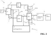
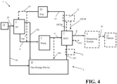
- exemplary embodiments of our apparatus 1 for warming a cryogenic liquid and re-cooling gas for recapture and recovery of cryogenic gas formed from cryogenic liquid can be positioned and arranged for improved processing performance that can help reduce cryogenic fluid losses to avoid losing such fluid to venting to atmosphere.
- Embodiments can provide improved operational efficiency by reducing fluid losses while also mitigating, if not avoiding, formation of fog associated with operation of the apparatus 1.
- Some embodiments of the apparatus 1 can be configured as a hydrogen storage and dispensing system and/or utilize a process for hydrogen storage and dispensing.
- Other embodiments of the apparatus 1 can be configured as other types of systems that can utilize other types of cryogenic fluid (e.g. methane, or natural gas, cryogenic oxygen that may be stored as a liquid for subsequent use as a gas, etc.).
- the apparatus 1 can include a cryogenic fluid storage tank 3 (ST) that can be configured to store liquid cryogenic fluid as well as gaseous cryogenic fluid that may form as a result of the storage of the liquid cryogenic fluid in the tank evaporating into a gas while the liquid is stored in the liquid cryogenic fluid storage tank 3.
- the cryogenic gas within the tank 3 may be in an upper portion of the tank above a liquid level within the tank.
- the cryogenic fluid stored in the tank can be hydrogen or another suitable cryogenic fluid (e.g. methane, oxygen, etc.).
- the storage tank 3 can be filled or refilled via at least one trailer 3T that can be connectable to the storage tank 3 via a trailer connection 2T.
- a cryogenic liquid within the trailer 3T can be fed to the tank to refill the tank, add additional cryogenic liquid to the tank 3, or otherwise provide additional cryogenic fluid to the tank 3 via the trailer connection 2T that is connectable between the trailer 3T and the storage tank 3.
- resupply of the cryogenic fluid to the storage tank 3 can be provided via another source of the fluid (e.g. a hydrogen formation device, etc.) that may be on the site of the apparatus.
- the storage tank 3 can be configured for the storage of a cryogenic fluid.
- the cryogenic liquid to be stored is hydrogen
- the temperature at which the fluid is stored in the storage tank can be in a pre-selected storage temperature range of -225°C to -280°C and the storage pressure can be in a pre-selected storage pressure range of 0.1 MPa to 3 MPa.
- the cryogenic liquid to be stored is oxygen
- the pre-selected storage temperature can be in a range of -219°C and - 125°C and the storage pressure can be in a pre-selected storage pressure range of 0.1 MPa to 3 MPa.
- Other cryogenic liquids can also be stored in the storage tank (e.g. liquid natural gas, liquid nitrogen, etc.).
- the pre-selected storage temperature and pre-selected storage pressure can be selected so the stored fluid is below the fluid's critical temperature to help minimize boil-off of the liquid.
- the storage tank 3 can be fluidly connected to a pump 5 via a pump feed conduit 4 positioned between the storage tank 3 and the pump 5.
- the pump 5 can be configured to drive a flow of liquid or help drive a flow of fluid that includes a mixture of liquid and gas.
- the pump 5 can be positioned to increase the pressure of the fluid for feeding the fluid to a vaporizer 7 (HXV) so that cryogenic liquid fed to the pump 5 can be vaporized into a gas.
- the fluid output from the pump 5 can have a pre-selected vaporizer feed pressure, which can be a pressure within the range of 20 MPa to 80 MPa, 20 MPa to 40 MPa, 30 MPa to 70 MPa, or other suitable pressure range, for example.
- a vaporizer feed conduit 6 can be positioned between the pump 5 and the vaporizer 7 to feed the cryogenic fluid from the pump 5 to the vaporizer 7.
- the vaporizer 7 can be positioned to heat the cryogenic fluid and output the cryogenic fluid as a cryogenic gas for feeding to a dispensing system 9.
- a vaporizer output conduit 8 can be positioned between the vaporizer 7 and the dispensing system 9 for feeding the warmed gas output from the vaporizer 7 to the dispensing system 9.
- the vaporizer 7 can include at least one heat exchanger (e.g. a plurality of heat exchangers or a single heat exchanger).
- the vaporizer 7 can be configured to utilize at least one heating medium.
- the heating medium fed to the vaporizer 7 can include gas formed via vaporization of the cryogenic liquid stored in the storage tank 3 when the liquid is warmed (e.g. during storage in the storage tank 3, via use in purge operations, residual gas of cryogenic liquid retained in a trailer 3T that may have been formed or fed to trailer during transit, gas formed during a pump cooldown operation, etc.).
- the vaporizer 7 can include more than one heat exchanger and the heating medium provided via the gas formed by the vaporized cryogenic liquid may not be sufficient for vaporizing the cryogenic liquid into a gas for outputting as a gas via the vaporizer output conduit 8.
- at least one additional heating medium can be utilized for vaporization of the cryogenic liquid in the vaporizer 7 for providing the warmed gas for feeding to the vaporizer output conduit 8.
- a heating medium can include, for example, ambient air.
- such an additional heating medium can also include or alternatively include a warmed refrigerant flow as discussed herein.
- the dispensing system 9 can include at least one dispenser for dispensing the gas to at least one vehicle 11 via at least one vehicle connection device 9f that can be positionable to fluidly connect the dispensing system 9 to the vehicle 11 for feeding the fluid to at least one fuel tank of the vehicle 11.
- the dispensing system 9 can also include a flow control manifold connected to one or more of the dispensers for distributing the cryogenic fluid to the dispenser to facilitate the fueling of a vehicle 11.
- the apparatus may provide the cryogenic fluid to another plant process.
- the vaporizer output conduit 8 can be positioned between the vaporizer 7 and another plant process element for feeding the warmed cryogenic fluid to the plant process element.
- the cryogenic fluid is oxygen and the apparatus 1 is configured to support furnace operations for combustion of a fuel or melting of metal (e.g. aluminum or steel)
- the vaporizer output conduit 8 can be positioned to provide a flow of oxidant to a furnace for combustion of a fuel in the furnace.
- the apparatus 1 can also include a vaporized gas recapture and recovery system 2 that is configured to recapture cryogenic liquid that is vaporized into a gas during storage, use as a purge stream, use in pump cooldown operations, and/or in other uses to avoid having to vent that gas formed from the cryogenic liquid.
- a vaporized gas recapture and recovery system 2 that is configured to recapture cryogenic liquid that is vaporized into a gas during storage, use as a purge stream, use in pump cooldown operations, and/or in other uses to avoid having to vent that gas formed from the cryogenic liquid.
- the vaporized gas recapture and recovery system 2 can be configured to recapture and recover gas in one or more of the following situations: (i) gas formed as the cryogenic liquid may warm during storage, (ii) gas formed when cryogenic liquid is used in a pump cooldown operation and/or a purge of a feed line, (iii) gas formed from the cryogenic liquid used for purging of a line and/or (iv) gas formed during a blowdown operation and/or gas output from a tank or trailer during a blowdown operation.
- the vaporized gas recapture and recovery system 2 can also be configured to collect other gas formed from the cryogenic liquid (e.g. due to evaporation, boil-off, warming during storage or use, etc.).
- the vaporized gas recapture and recovery system 2 can include a gas storage device 10.
- the gas storage device 10 can include one or more gas storage vessels 30.
- the gas storage vessels 30 can be configured to store the gas formed from the cryogenic liquid when the gas is warmed and no longer at a cryogenic temperature.
- the warming of the gas fed to the gas storage device 10 can be provided via at least one warming tank, conduit paths for feeding the formed gas to the gas storage device, use of an enlarged conduit segment within the gas feed conduit for feeding gas to the gas storage device to facilitate warming of the gas to a non-cryogenic temperature, or other mechanisms or configurations to facilitate warming of the gas to a non-cryogenic temperature for storage in one or more storage vessels 30 of the gas storage device 10.
- the non-cryogenic temperature for storage of the gas can be a temperature that is greater than -100°C, between -100°C and 50°C, between -100°C and 25°C, or other suitable storage temperature within a pre-selected gas storage temperature range.
- the gas storage device 10 can include at least one gas storage vessel 30 and can also include a pressure increasing mechanism C.
- the pressure increasing mechanism C can be incorporated into a storage vessel 30, incorporated into the gas storage device 10, or can be positioned between the gas storage device 10 and the vaporizer 7 for increasing pressure of a gas feed 10f to be fed to the vaporizer 7 to function as a heating medium therein for warming the cryogenic liquid output from the storage tank 3 that can be fed to the vaporizer 7 via the pump 5 and vaporizer feed conduit 6.
- the gas feed 10f can be fed to the vaporizer 7 via a vaporizer heating medium feed conduit positioned between the gas storage device 10 and the vaporizer 7.
- the pressure increasing mechanism C can be connected to the vaporizer heating medium feed conduit or be integrated into that conduit for increasing the pressure of the gas feed 10f to a pre-selected heating medium pressure that is within a pre-selected vaporizer heating medium pressure range.
- the pressure increasing mechanism C can include a compressor, a pump, a bump tank, or other device that is configured to increase the pressure of the gas for feeding to the vaporizer 7 as a heating medium at a pre-selected heating medium pressure that is within a pre-selected vaporizer heating medium pressure range.
- This pressure range can be in the range of 0.1 MPA to 3 MPa, between .5 MPa and 1 MPa, between .3 MPa and 1.5 MPa, or other suitable range.
- the pressure increasing mechanism C (when utilized) can be positioned between the gas storage device 10 and the vaporizer 7 to output the gas at the pre-selected vaporizer heating medium pressure via a vaporizer heating medium feed conduit 10fc positioned between the vaporizer 7 and the gas storage device 10 and/or positioned between the pressure increasing mechanism C and the vaporizer 7.
- the increasing pressure mechanism can be at least one heating element for heating a storage vessel 30 that is configured as a metal hydride storage vessel 33 that can heat the vessel so that hydrogen stored in the vessel can be released from the vessel 30 at an increased pressure that is within the pre-selected vaporizer heating medium pressure range for feeding to the vaporizer via the vaporizer heating medium feed conduit positioned between the vaporizer 7 and the gas storage device 10.
- the vaporized gas recapture and recovery system 2 can also include an arrangement of feed conduits for recovering cryogenic gas or other gas formed from the cryogenic liquid vaporizing (e.g. evaporating, boiling off, etc.) from different units of the apparatus 1 and conveying it to the gas storage device 10 and an arrangement of output conduits so gas stored in the gas storage device 10 can be fed to the vaporizer 7 and subsequently routed to the storage tank 3 and/or conduit downstream of the vaporizer 7 (e.g. vaporizer output conduit 8, etc.).
- cryogenic gas or other gas formed from the cryogenic liquid vaporizing e.g. evaporating, boiling off, etc.
- the vaporized gas recapture and recovery system 2 can also include an arrangement of feed conduits for recovering cryogenic gas or other gas formed from the cryogenic liquid vaporizing (e.g. evaporating, boiling off, etc.) from different units of the apparatus 1 and conveying it to the gas storage device 10 and an arrangement of output conduits so gas stored in the gas storage device 10 can be fed to
- the vaporized gas recapture and recovery system 2 can also include at least one expansion mechanism 12 (Exp.) and/or at least one cooling device 21 positioned for cooling and/or facilitating at least partial liquefaction of the cooled gas used as the heating medium in the vaporizer 7 after it is output from the vaporizer 7 as a cooled heating medium stream via cooled heating medium output conduit 14 that can be connected to the vaporizer 7.
- expansion mechanism 12 Ex.
- cooling device 21 positioned for cooling and/or facilitating at least partial liquefaction of the cooled gas used as the heating medium in the vaporizer 7 after it is output from the vaporizer 7 as a cooled heating medium stream via cooled heating medium output conduit 14 that can be connected to the vaporizer 7.
- these components can be connected to the arrangement of output conduits of the vaporized gas recapture and recovery system 2.
- the cooled heating medium output conduit 14 can be a component of the arrangement of output conduits of the vaporized gas recapture and recovery system 2.
- the cooled heating medium output conduit 14 can include a cooling device feed conduit 14a and an expansion mechanism feed conduit 14b in embodiments that utilize a cooling device 21.
- the vaporizer heating medium feed conduit for the gas feed 10f to be fed to the vaporizer 7 can be a component of the arrangement of output conduits of the vaporized gas recapture and recovery system 2.
- the arrangement of output conduits of the vaporized gas recapture and recovery system 2 can also include other conduits.
- the arrangement of output conduits of the vaporized gas recapture and recovery system 2 can include a storage tank recovery conduit 16, a recovery pump feed conduit 16p, and/or a cryogenic gas recovery supply conduit 16a as discussed below.
- the arrangement of feed conduits can include at least one trailer gas feed conduit 20 that is positioned between the gas storage device 10 and the trailer connection 2T and/or trailer 3T for feeding cryogenic gas toward at least one storage vessel 30 of the gas storage device 10 for storage of the gas formed from the cryogenic liquid to the gas storage device 10.
- the trailer gas feed conduit 20 can be positioned so the cryogenic gas formed when cryogenic liquid from a trailer 3T is passed through the trailer connection 2T to cool down the elements of the connection as a purge stream can be captured and fed to the gas storage device 10 for storage and use instead of being vented.
- the purge stream that is captured for feeding to the gas storage device 10 can undergo purification via at least one purification unit (e.g. adsorber having adsorbent material therein for removing impurities from the captured purge stream, etc.) prior to being fed to the storage device 10 in some embodiments.
- a purification unit e.g. adsorber having adsorbent material therein for removing impurities from the captured purge stream, etc.
- Such a purification unit can be incorporated into the trailer gas feed conduit 20 and/or included in that conduit, for example.
- the trailer gas feed conduit 20 can also, or alternatively, be positioned so that cryogenic gas within the trailer 3T (e.g. gas that may have been formed while the cryogenic liquid within the trailer was being stored in the trailer 3T) can be passed through the trailer gas feed conduit to at least one storage vessel 30 for storage of the gas during a trailer blowdown operation.
- cryogenic gas within the trailer 3T e.g. gas that may have been formed while the cryogenic liquid within the trailer was being stored in the trailer 3T
- This type of blowdown operation can occur prior to the trailer 3T being moved off site to help ensure the pressure within the trailer 3T is below a preselected threshold or can be provided prior to the feeding of the cryogenic liquid to the storage tank 3 to avoid an over pressure condition within the trailer 3T.
- the arrangement of feed conduits of the vaporized gas recapture and recovery system 2 can also (or alternatively) include a pressure reduction conduit 10a that is connectable between the storage tank 3 and the gas storage device 10 (e.g. at least one storage vessel 30 of the gas storage device 10) so that cryogenic gas formed in the tank 3 while the cryogenic liquid is stored therein can be removed from the tank 3 and fed to at least one storage vessel 30 of the gas storage device 10 instead of being vented to atmosphere.
- This type of removal of cryogenic gas from the tank 3 can occur periodically to reduce the pressure in the tank 3 to maintain the pressure within the tank at or below a pre-selected tank storage pressure.
- cryogenic gas can be formed during the storage time (e.g.
- the periodic removal of the formed cryogenic gas can reduce the pressure within the tank 3 and keep that pressure at or below the pre-selected tank storage pressure.
- This type of pressure reduction can occur periodically in response to a detection of the pressure within the tank being at or above a pre-selected threshold, which can be the pre-selected tank storage pressure.
- the detection can be provided via a regulator or a pressure sensor positioned to monitor or measure the pressure of the tank 3.
- a controller can be configured to actuate a valve to open a valve of the tank so that cryogenic gas can be output from the tank to be fed to at least one vessel 30 of the gas storage device 10 for storage of the gas via pressure reduction conduit 10a, which can be connected between the storage tank 3 and the gas storage device 10.
- the gas stored via the gas storage device 10 can be at a non-cryogenic temperature due to warming of the gas that can occur during the passing of the gas toward at least one storage vessel 30 of the gas storage device 10.
- This removal of cryogenic gas from the tank 3 and conveying of the gas to the gas storage device 10 can permit the gas to be re-cooled and recaptured instead of being vented to atmosphere to alleviate an over pressure condition within the tank 3.
- This pressure reduction conduit 10a can also be utilized during a blowdown operation to reduce the pressure within the tank 3 to remove cryogenic gas within the tank 3 to facilitate further filling of the tank 3 with cryogenic liquid to be output from a trailer 3T to be fed to the tank 3 via the trailer connection 2T.
- the tank blowdown operation utilizing the pressure reduction conduit 10a can occur at the same time the above mentioned trailer blowdown operation is performed such that cryogenic gas from the trailer 3T is provided to the gas storage device 10 via trailer gas feed conduit 20 and cryogenic gas from the tank 3 is provided to the gas storage device 10 via pressure reduction conduit 10a.
- This type of blowdown operation can occur before, during or after the above mentioned trailer connection 2T purge operation is performed.
- the cryogenic liquid can vaporize as it cools the pump 5 and the cryogenic gas formed via the pump cooldown can be output from the pump and fed to at least one vessel 30 of the gas storage device 10 via a pump cooldown output conduit 10b positioned between the pump 5 and the gas storage device 10.
- a pump cooldown feed conduit 10pc can be connected between the pump 5 and the storage tank 3 to feed cryogenic fluid from the tank 3 to the pump 5 for cooling down the pump 5.
- the cryogenic fluid can subsequently be output from the pump 5 as cryogenic gas that is output from the pump 5 for being fed to at least one storage vessel 30 of the gas storage device 10 via the pump cooldown output conduit 10b positioned between the pump 5 and the gas storage device 10.
- the cryogenic fluid output from the tank 3 for being passed through the pump cooldown feed conduit 10pc can be cryogenic gas that is within the tank 3 in some embodiments.
- the inlet for the pump cooldown feed conduit 10pc can be positioned above an anticipated liquid level of the tank 3 so that cryogenic gas is output from the tank 3 for passing to the pump cooldown feed conduit 10pc for the pump cooldown operation and subsequent storage of that cryogenic gas.
- the pump cooldown feed conduit 10pc can be connected between the pump 5 and the pressure reduction conduit 10a for providing the cryogenic gas from the tank 3 to the pump 5 for performance of the pump cooldown operation and subsequent feeding of the cryogenic gas to the gas storage device 10.
- the vaporized gas recapture and recovery system 2 can also include at least one expansion mechanism 12 (Exp.) and/or at least one cooling device 21 positioned for cooling and/or facilitating at least partial liquefaction of the cooled cryogenic gas used as the heating medium in the vaporizer 7 after it is output from the vaporizer 7 as a cooled heating medium stream via cooled heating medium output conduit 14 that can be connected to the vaporizer 7.
- the cooled gas used as the heating medium in the vaporizer 7 output from at least one storage vessel 30 of the gas storage device 10 can be output from the vaporizer 7 via cooled heating medium output conduit 14 and subsequently fed to an expansion mechanism 12 (Exp.) to reduce the pressure of this fluid to a pre-selected storage tank feed pressure.
- Such a pre-selected storage tank feed pressure can be a pressure of between 0.1 MPa and 3 MPa in some embodiments.
- the expansion mechanism 12 can include a control valve, a Joule-Thomson valve, an expander, a combination of such units, or other suitable pressure reduction device.
- the pressure reduction provided by the expansion mechanism 12 can also function to cool the fluid.
- the pressure reduction and cooling that may be provided via the expansion mechanism 12 may partially liquefy or fully liquefy the gas while its pressure is reduced.
- the pressure reduction and cooling that may be provided via the expansion mechanism 12 can further cool the gas without even partially liquefying the gas to help maintain pressure within the storage tank 3 and help limit cryogenic liquid boil-off that may occur while the cryogenic liquid is stored in the tank 3.
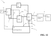
- the fluid output from the expansion mechanism 12 can be fed to the storage tank 3 via a storage tank recovery conduit 16 positioned between the storage tank 3 and the expansion mechanism 12 and/or can be fed to the pump 5 via a recovery pump feed conduit 16p positioned between the expansion mechanism 12 and the pump 5 (e.g.
- the fluid can be fed to the pump 5 for being fed toward the vaporizer 7 for vaporization and/or warming therein for being output as warmed gas via the vaporizer output conduit 8.
- Figure 12 illustrates an exemplary implementation of the embodiment shown in Figure 1 that can provide a flow of fluid from the expansion mechanism 12 to the pump 5, for example.
- the fluid fed to the pump 5 via the recovery pump feed conduit 16p can be cooled gas, cryogenic liquid, or a mix of liquid and gas.
- the gas can be fed to the storage tank 3 so that the gas is fed below a liquid level line of the storage tank 3 so the gas is passed through the cryogenic liquid of the storage tank 3 (e.g. the gas can be bubbled through the liquid of the storage tank 3).
- This bubbling of the recovered gas can help cool that gas fed to the storage tank 3 via the storage tank recovery conduit 16 to reduce the volume of the gas being fed to the tank, may help liquify a portion of the gas, and/or can provide other advantages that can outweigh the warming of the stored liquid that may occur from feeding the gas through the liquid of the storage tank 3.
- an outlet of the storage tank recovery conduit 16 can be positioned to be a pre-selected distance below an anticipated liquid level position of the storage tank 3 or positioned at or adjacent a bottom of the storage tank 3.
- At least one cooling device 21 can be connected to the cooled heating medium output conduit 14.
- the at least one cooling device 21 can be a chiller (e.g. an absorption chiller) or a heat exchanger that uses a cooling medium from another plant process for cooling of the gas used as a heating medium in the vaporizer 7 that is output from the vaporizer as the cooled heating medium via the cooled heating medium output conduit 14.
- the at least one cooling device 21 can be configured to utilize a refrigerant that can be used to cool the cryogenic gas output from the vaporizer as the cooled heating medium and also function as a heating medium in the vaporizer 7 for providing additional heat to the cryogenic liquid being warmed via the vaporizer via a refrigerant heating medium feed conduit 22CM connected between the cooling device 21 and the vaporizer 7.
- a refrigerant that can be used to cool the cryogenic gas output from the vaporizer as the cooled heating medium and also function as a heating medium in the vaporizer 7 for providing additional heat to the cryogenic liquid being warmed via the vaporizer via a refrigerant heating medium feed conduit 22CM connected between the cooling device 21 and the vaporizer 7.
- cooling device 21 may best be appreciated from the exemplary embodiments of the cooling device 21 illustrated in Figure 9 and 10 , which illustrate different exemplary options for use of a refrigerant heating medium feed conduit 22CM for different configurations of the cryogenic liquid vaporizer 7 that can be used in the exemplary embodiment of the apparatus 1 for warming a cryogenic liquid and re-cooling gas for recapture and recovery of gas formed from the storage or use of the cryogenic liquid shown in Figures 1-4 .
- the cooling device 21 can include a cooling heat exchanger 21cd for further cooling the cooled gas output from the vaporizer 7 via the cooled heating medium output conduit 14.
- the cooling heat exchanger 21cd can receive the cooled gas from the vaporizer via a cooling device feed conduit 14a positioned between the vaporizer 7 and the cooling heat exchanger 21cd of the cooling device 21.
- the cooling heat exchanger 21cd can utilize a refrigerant for further cooling the gas to a pre-selected cryogenic stream recovery temperature.
- This temperature can be selected to help liquify at least a portion of the gas via the expansion mechanism 12 or help provide full liquefaction of the gas after it is passed through the expansion mechanism 12, which can be positioned between the storage tank 3 and the cooling heat exchanger 21 cd.
- the further cooled gas output from the cooling heat exchanger 21cd can be fed toward the tank 3 via an expansion mechanism feed conduit 14b positioned between the expansion mechanism 12 and the cooling heat exchanger 21cd.
- the pre-selected cryogenic stream recovery temperature can be selected so that the further cooled gas passed through the expansion mechanism feed conduit 14b also includes some liquid from condensation of the gas that may occur from the temperature reduction of the gas via the cooling heat exchanger 21cd.
- the refrigerant used in the cooling heat exchanger 21cd of the cooling device 21 can be fed to the cooling heat exchanger 21cd via a refrigerant feed conduit 21Rin.
- the warmed refrigerant used as the cooling medium in the cooling heat exchanger 21cd can be output from the cooling heat exchanger 21cd via a refrigerant output conduit 21Rout positioned between the cooling heat exchanger 21cd and the vaporizer 7.
- the cooling device 21 can include a refrigerant pressure increasing device 21PC that can be positioned to receive the warmed refrigerant via the refrigerant output conduit 21Rout to increase the pressure of the refrigerant to a pre-selected vaporizer feed pressure.
- the refrigerant's pre-selected vaporizer feed pressure can be a suitable pressure that can be selected to account for the feed pressure for feeding the refrigerant to the vaporizer 7 for use as a heating medium therein, the type of refrigerant that is selected and its material properties, and the flow rate of refrigerant to be utilized.
- the refrigerant pressure increasing device 21PC can be, for example, a pump or a compressor.
- the warmed refrigerant can be output from the refrigerant pressure increasing device 21PC at the pre-selected vaporizer feed pressure for being fed as a heating medium for the vaporizer 7 via the heating medium feed conduit 22CM.
- the vaporizer 7 can output the refrigerant as a cooled refrigerant that is at a pre-selected refrigerant feed temperature for feeding the refrigerant to the cooling device 21 for being fed to the cooling heat exchanger 21cd.
- the cooled refrigerant can be output from the vaporizer 7 and fed to a refrigerant pressure let down device 21pld of the cooling device 21 to reduce the pressure of the refrigerant for feeding to the cooling heat exchanger 21cd via a pressure let down device feed conduit 24CM positioned between the vaporizer 7 and the refrigerant pressure let down device 21pld.
- the refrigerant pressure let down device 21pld can reduce the pressure of the refrigerant, which can also further cool the refrigerant to a pre-selected cooling heat exchanger refrigerant feed temperature for feeding the refrigerant to the cooling heat exchange via refrigerant feed conduit 21Rin for use as a cooling medium therein for further cooling of the gas to be further re-cooled for returning that fluid to the storage tank 3 via storage tank recovery conduit 16 and/or the pump 5 via recovery pump feed conduit 16p.
- the refrigerant utilized as a cooling medium for the cooling heat exchanger 21cd of the cooling device 21 can be a fluid comprising hydrogen or helium.
- the refrigerant can include a fluid that is at least 99 mole percent (mol%) hydrogen (e.g. between 99 mol% hydrogen to 100 mol% hydrogen) or at least 99 mol% helium (e.g. between 99 mol% helium to 100 mol% helium).
- the pre-selected cooling heat exchanger refrigerant feed temperature can be a temperature in the range of -300°C to -400°C or other suitable range.
- An example of a pre-selected cooling heat exchanger refrigerant feed pressure at which the refrigerant is output from the refrigerant pressure let down device 21pld for being fed to the cooling heat exchange via refrigerant feed conduit 21Rin can be a pressure in the range of 0.1 MPa and 10 MPa.
- the vaporizer 7 can be configured to utilize multiple heat exchangers in series, which can include a first heat exchanger HX1 and a second heat exchanger HX2.
- the first heat exchanger HX1 can receive the gas from at least one vessel 30 of the gas storage device 10 as the gas feed 10f for use as a heating medium therein for warming the cryogenic liquid output from the pump 5 that is fed to the vaporizer 7.
- the cryogenic liquid may only be partially vaporized via the first heat exchanger HX1, may be vaporized but at an insufficiently high temperature, or may be heated without being sufficiently heated for vaporization via the first heat exchanger HX1.
- a second heat exchanger HX2 can receive the heated fluid or at least partially vaporized fluid output from the first heat exchanger HX1 via a second heat exchanger feed conduit 5i positioned between the first heat exchanger HX1 and the second heat exchanger HX2.
- the second heat exchanger HX2 of the vaporizer 7 can receive warmed refrigerant output from the cooling device 21 via the heating medium feed conduit 22CM so the warmed refrigerant can be cooled back to a pre-selected refrigerant feed temperature while also providing heat for warming of the cryogenic liquid stream fed to the vaporizer for outputting the warmed cryogenic liquid output from the pump 5 as a gas via vaporizer output conduit 8.
- the cooled refrigerant that was used as the heating medium in the second heat exchanger HX2 can be output from the second heat exchanger HX2 for being fed to a refrigerant pressure let down device 21pld of the cooling device 21 via the pressure let down device feed conduit 24CM positioned between the second heat exchanger HX2 of the vaporizer 7 and the refrigerant pressure let down device 21pld.
- the vaporizer 7 can be configured to include a first heat exchanger HX1 that can receive the gas from at least one vessel 30 of the gas storage device 10 as the gas feed 10f for use as a heating medium therein for warming the cryogenic liquid output from the pump 5 that is fed to the vaporizer 7 and also receive the warmed refrigerant from the cooling device 21 as a heating medium for use therein for warming the cryogenic liquid.
- a first heat exchanger HX1 can receive the gas from at least one vessel 30 of the gas storage device 10 as the gas feed 10f for use as a heating medium therein for warming the cryogenic liquid output from the pump 5 that is fed to the vaporizer 7 and also receive the warmed refrigerant from the cooling device 21 as a heating medium for use therein for warming the cryogenic liquid.
- the first heat exchanger HX1 of the vaporizer 7 can receive warmed refrigerant output from the cooling device 21 via the heating medium feed conduit 22CM so the warmed refrigerant can be cooled back to the pre-selected refrigerant feed temperature while also providing heat for warming of the cryogenic liquid stream fed to the vaporizer 7 for outputting the vaporized cryogenic liquid output from the pump 5 as a gas via vaporizer output conduit 8.
- the cooled refrigerant that was used as the heating medium in the first heat exchanger HX1 can be output from the first heat exchanger HX1 for being fed to a refrigerant pressure let down device 21pld of the cooling device 21 via the pressure let down device feed conduit 24CM positioned between the first heat exchanger HX1 of the vaporizer 7 and the refrigerant pressure let down device 21pld.
- the cooling device 21 can utilize a refrigerant buffer tank 25 (RT) that can store additional refrigerant therein so that such refrigerant can be added to the circuit of refrigerant flow to make up for any lost refrigerant that may occur during use (e.g. imperfect seals, leaks, etc.).
- a refrigerant makeup conduit 26 can be connected between the refrigerant buffer tank 25 and a conduit of the refrigerant circuit (e.g. the refrigerant heating medium feed conduit 22CM, the refrigerant output conduit 21Rout, the pressure let down device feed conduit 24CM, etc.) for providing refrigerant makeup as may be needed during operations.
- a valve of the refrigerant makeup conduit 26 can be adjusted between open and closed positions to facilitate such a flow of refrigerant makeup fluid.
- the heating that may be provided by the gas output from the gas storage device 10 as well as warmed refrigerant that may be provided by a cooling device 21 may not be sufficient for vaporization of the cryogenic liquid.
- the vaporizer can include an additional heat exchanger that can utilize another flow of heating medium AA, which can be ambient air or other type of heating medium for providing additional source of heat for vaporization of the cryogenic liquid.
- the vaporizer 7 can include a third heat exchanger HX3 shown in broken line in Figures 9 and 10 that may utilize another flow of another heating medium AA.
- the vaporizer 7 can include a second heat exchanger in situations where a first heat exchanger of the vaporizer 7 may utilize the gas output from the gas storage device 10 as the heating medium and a second heat exchanger downstream of that heat exchanger can be utilized for use of the other flow of heating medium AA.
- the captured cryogenic gas retained via the gas storage device 10 can be entirely or at least partially provided as cryogenic gas downstream of the vaporizer 7.
- the cooled cryogenic gas fed to the vaporizer as a heating medium that is output from the vaporizer via the cooled heating medium output conduit 14 can be fed for merging with the cryogenic gas output from the vaporizer 7 via the vaporizer output conduit 8.
- a cryogenic gas recovery supply conduit 16a can be connected between the vaporizer output conduit 8 and the cooled heating medium output conduit 14 for providing the gas from the gas storage device 10 to the vaporizer output conduit gas after being used as a heating medium in the vaporizer 7.
- all the gas can be recovered via being passed downstream of the vaporizer 7 for mixing with the vaporized cryogenic liquid output from the vaporizer 7 as cryogenic gas via the cryogenic gas recovery supply conduit 16a or a portion of that gas can be passed downstream of the vaporizer 7 via the cryogenic gas recovery supply conduit 16a and another portion of this fluid can be fed back to the storage tank 3.
- a phase separator PS can be positioned between the storage tank 3 and the cooled heating medium output conduit 14 for separation of liquid and gas that may be formed from the gas output to the cooled heating medium output conduit 14 or subsequently further cooled via the cooling device 21 and/or expansion mechanism 12.
- the phase separator PS can be positioned between the expansion mechanism 12 and the storage tank 3. Liquid of this further cooled stream can be output from the phase separator PS for being fed to the tank 3 via the storage tank recovery conduit 16 that can be connected between the phase separator PS and the storage tank 3 or the pump 5 via the recovery pump feed conduit 16p that can be connected between the phase separator PS and the pump 5.
- Gas output from the phase separator PS can be fed to the cryogenic gas recovery supply conduit 16a via a phase separator gas output conduit 16b connected between the phase separator PS and the cryogenic gas recovery supply conduit 16a for providing the cryogenic gas output from the phase separator PS for further use downstream of the vaporizer 7 (e.g. for use in fuel dispensing via dispensing system 9 or use in another downstream process that may use the cryogenic gas).
- the gas output from the phase separator PS can be fed to the gas storage device 10 via a gas storage device feed conduit 16c connected between the phase separator PS and the gas storage device 10 for providing the cryogenic gas output from the phase separator PS.
- the phase separator gas output conduit 16b can be connected to the gas storage device feed conduit 16c for feeding the gas output from the phase separator PS to the gas storage device 10.
- a gas storage device feed conduit 16c can include a compressor or other flow driving mechanism to help facilitate the flow of the gas from the phase separator PS to the gas storage device 10.
- the gas output from the phase separator PS that is fed to the gas storage device 10 can be stored therein and re-used as a heating medium for the vaporizer 7 and subsequently passed back through other elements for being fed to the pump 5, storage tank 3 and/or again recycled back to the gas storage device 10.
- the gas storage device 10 (Gas Storage Device) can be configured in various different ways. Exemplary arrangements for the gas storage device 10 are shown in Figures 5-8 . Other configurations can also be utilized in other embodiments of the gas storage device 10 as well.
- the gas storage device 10 can include a plurality of storage vessels (e.g. examples shown in Figures 5 and 6 , or only a single storage vessel 30 (e.g. example embodiments shown in Figures 7 and 8 ). Some of the storage vessels 30 can be arranged in series while one other storage vessel 30 can be utilized in parallel or as an alternative source of the gas for providing to the vaporizer 7 as a heating medium for subsequently being re-cooled and recaptured or re-used as discussed herein.
- the gas storage device 10 can include a first gas storage vessel 30 that is configured as a buffer tank 31 and a second gas storage vessel 30 that is configured as a metal hydride storage vessel 33 that is downstream of the buffer tank to receive gas from the buffer tank for storage therein.
- the first and second gas storage vessels 30 that are configured as the buffer tank 31 and metal hydride storage vessel 33 can be configured for the receipt and storage of a gas that may have purity concerns so that the metal hydride storage vessel 33 can store the sufficiently purified gas while removing the impurities from that gas.
- the first storage vessel 30 that can be configured as a feed buffer tank 31 can receive a first gas stream 31a that is for feeding to the second storage vessel 30 that is configured as a metal hydride storage vessel 33 for storage of the gas having improved purity via that storage.
- the buffer tank 31 can be sized to accommodate a large flow of gas fed to the vessel 30 as the first gas stream 31a that can subsequently be provided at a slower flow rate to the second storage vessel 30 to accommodate the rate of storage that can be provided by the metal hydride storage vessel 33 via a second storage vessel feed conduit 10g positioned between the first storage vessel 30 and the second storage vessel 30 configured as the metal hydride storage vessel 33.
- cryogenic gas obtained from when cryogenic gas is formed when cryogenic liquid from a trailer 3T is passed through the trailer connection 2T to cool down the elements of the connection as a purge stream can be recovered and fed to the first storage vessel as the first gas stream 31a.
- This purge stream may have higher impurity contents due to the interaction of the purge stream with the trailer connection 2T elements and may be fed to the metal hydride storage vessel 33 as the storage of the gas via the metal hydride storage vessel 33 can facilitate storage of a purified gas that does not include those impurities due to the metal hydride elements of the storage vessel.
- the buffer tank 31 can provide an intake mechanism to permit the high rate of the cryogenic gas to be accommodated so the purge operations can occur quickly while also permitting the slower intake rate of the metal hydride storage vessel 33 to be accommodated.
- cryogenic gas of the first gas stream 31a can be provided via multiple different conduits of the arrangement of feed conduits for recovering cryogenic gas of the vaporized gas recapture and recovery system 2.
- the first gas stream 31a can include the cryogenic gas obtained via cryogenic gas that is formed when cryogenic liquid from a trailer 3T is passed through the trailer connection 2T to cool down the elements of the connection as a purge stream that can be fed to the gas storage device via trailer gas feed conduit 20 and the cryogenic gas that is received via trailer blowdown operations that can be received via the trailer gas feed conduit 20.
- this cryogenic gas can be warmed to a non-cryogenic temperature via passing through a conduit for being fed to a storage vessel of the gas storage device 10.
- the first gas stream 31a can also (or alternatively) include cryogenic gas from the tank 3 that is provided to the gas storage device 10 via pressure reduction conduit 10a that may be provided via tank pressure reduction operations to maintain the pressure of the storage tank 3 as discussed above and/or tank blowdown operations that may be performed for feeding additional cryogenic liquid to the tank 3 via at least one trailer 3T via trailer connection 2T as discussed above.
- the first gas stream 31a can also (or alternatively) include cryogenic gas obtained via pump cooldown operations via the pump cooldown output conduit 10b. As noted above, these flows of cryogenic gas that can be fed to the gas storage device 10 can be warmed to a non-cryogenic temperature for being fed to a storage vessel of the gas storage device 10 (e.g. warmed via passing through at least one conduit, etc.).
- the gas storage device 10 can also include a third storage vessel 30 as may best be appreciated from Figure 5 .
- the third storage vessel 30 can be configured as a gas storage vessel 35 for receiving a second gas stream 35a for storage from at least one source of cryogenic gas (e.g. pump cooldown operations and/or storage tank venting operations).
- the gas of the second gas stream 35a can have a higher purity of cryogenic gas as compared to the first gas stream 31a.
- gas from pump cooldown operations via pump cooldown output conduit 10b and/or storage tank 3 pressure reduction and/or blowdown operations via pressure reduction conduit 10a can be fed to the third storage vessel 35 as the second gas stream 35a.
- the gas received from these operations may be at a higher purity content as compared to other sources of the gas that can be provided to the first storage vessel 30 via the first gas stream 31a (e.g. greater concentration of hydrogen gas as compared to other sources in some embodiments where the storage tank 3 is configured for storage of liquid hydrogen, greater concentration of oxygen gas as compared to other sources in some embodiments where the storage tank 3 is configured for storage of liquid oxygen, etc.).
- the first gas stream 31a can include gas that is formed when cryogenic liquid from a trailer 3T is passed through the trailer connection 2T to cool down the elements of the connection as a purge stream that can be fed to the gas storage device 10 via trailer gas feed conduit 20 and/or the cryogenic gas that is received via trailer blowdown operations that can be received via the trailer gas feed conduit 20.
- the first cryogenic stream 31a can include cryogenic gas that is formed when cryogenic liquid from a trailer 3T is passed through the trailer connection 2T to cool down the elements of the connection as a purge stream that can be fed to the gas storage device via trailer gas feed conduit 20 and the second gas stream 35a can include cryogenic gas that is received via trailer blowdown operations that can be received via the trailer gas feed conduit 20 as well as gas from pump cooldown operations via pump cooldown output conduit 10b and storage tank 3 pressure reduction and storage tank blowdown operations via pressure reduction conduit 10a can be fed to the third storage vessel 35 as the second gas stream 35a.
- the device can include a single storage vessel 30.
- the single storage vessel 30 can be configured as a metal hydride storage vessel 33 for storage of the cryogenic gas received as the first gas stream 31a and subsequent use of that gas.
- An example of such an arrangement can be seen in Figure 8 in implementations that do not utilize the broken line elements shown in Figure 8 .
- the release and use of the stored gas can be provided via one or more heating elements that can heat the metal hydride storage vessel 33 to increase the pressure and temperature of the stored gas so the stored gas can be output from the gas storge device 10 as cryogenic gas feed 10f.
- the storage vessel 30 can be a tank 31 that can be configured to store the gas and a pressure increasing mechanism C (e.g. compressor, etc.) can be positioned for driving a flow of the cryogenic gas feed 10f from the gas storage device 10 to the vaporizer 7.
- a pressure increasing mechanism C e.g. compressor, etc.
- FIG. 7 An example of such an arrangement is shown in Figure 7 .
- the gas storage device 10 can include multiple storage vessels 30 that can operate in parallel or otherwise.
- Figures 5 and 8 illustrate examples of such an embodiment.
- a first storage vessel 30 can be configured as a metal hydride storage vessel 33 for storage of the cryogenic gas provided via the first gas stream 31a and subsequent use of that gas.
- the release and use of the stored gas can be provided via one or more heating elements that can heat the metal hydride storage vessel 33 to increase the pressure and temperature of the stored gas so the stored gas can be output from the gas storge device 10 as cryogenic gas feed 10f.
- a second storage vessel 30 can be positioned as a second gas storage vessel 35 for receiving a second gas stream 35a therein.
- the cryogenic gas from the second gas stream 35a can be output from the second gas storage vessel 35 via a pressure increasing mechanism C (e.g. compressor, etc.) positioned to drive a flow of the cryogenic gas feed 10f to be output from the second gas storage vessel 35 via a second gas storage vessel output conduit 10h that is connected to a pressure increasing mechanism C positioned between the vaporizer 7 and the gas storage device 10 or via a second gas storage vessel output conduit 10i that is positioned in communication with a pressure increasing mechanism C of the gas storage device 10 drive a flow of the cryogenic gas feed 10f to be output from the second gas storage vessel 35 of the gas storage device 10.
- a pressure increasing mechanism C e.g. compressor, etc.
- the gas storage device 10 can be configured to receive the first gas stream 31a and the second gas stream 35a, different storage vessels 30 can be configured to store the gas at different storage pressures.
- the first vessel 30 that receives the first gas stream 31a can receive the gas and store the gas at a pressure that is higher or lower than the pressure at which the other vessel 35 receives the second gas stream 35a and/or stores that gas.
- the storage capacity of the one or more vessels 30 of the gas storage device 10 can be sized and configured to receive cryogenic gas for storage and use of that gas. Sizing can be adapted to meet a pre-selected set of criteria.
- gas stored in gas storage device 10 for use as a vaporizer heating medium may not be sufficient for full vaporization of the cryogenic liquid output from the pump 5.
- another heating medium can also be fed to the vaporizer 7 (e.g. ambient air and/or warmed refrigerant from the cooling device 21 when utilized, etc.).
- the gas storage device 10 can receive gas formed from evaporation of cryogenic liquid that may occur or can store gas formed from the cryogenic liquid that is no longer a cryogenic gas due to it warming to a sufficient temperature that the gas is no longer cryogenic in temperature.
- the gas storage device 10 can store the gas it receives so that the gas is warmed during storage so it can be more effectively used as a heating medium in the vaporizer 7.
- the storage device 10 can be configured and utilized to output the gas that is stored therein as a non-cryogenic gas that can be fed to the vaporizer 7, for example. This gas stored via the gas storage device 10 may then undergo cooling via use as a heating medium in the vaporizer 7 as well as other cooling (e.g.
- cryogenic gas or to at least partially liquify the gas to form cryogenic liquid and/or a mixture of cryogenic gas and cryogenic liquid for recapture of the stored gas as a cryogenic fluid.
- Embodiments of our process for warming a cryogenic liquid and re-cooling gas for recapture and recovery of that cryogenic gas can be utilized in embodiments of our apparatus 1 and/or embodiments of our vaporized gas recapture and recovery system 2. Examples of such process can be appreciated from the above as well as the exemplary embodiment illustrated in Figure 11 .
- the process can include a first step S1 that can include feeding gas from a cryogenic liquid storage tank 3, gas from a cryogenic liquid trailer 3T, purge gas from a trailer connection 2T, and/or pump cool down fluid to a gas storage device 10.
- Gas formed from the cryogenic liquid from one or other processes of a system or the apparatus can also be fed to the gas storage device 10 for storage and use instead of being vented as well.
- another waste stream that includes the process gas e.g. gas of the cryogenic liquid stored in storage tank 3
- the gas can be fed to the gas storage device 10 as a first gas stream 31a or as a first gas stream 31a and a second gas stream 35a in some embodiments.
- the feeding of the cryogenic gas to the gas storage device 10 can be provided via the arrangement of feed conduits for recovering cryogenic gas from different units of the apparatus 1 included in the vaporized gas recapture and recovery system 2, as discussed above.
- the gas stored in the gas storage device 10 can be output from the gas storage device 10 to the vaporizer 7 for warming cryogenic liquid output from the storage tank 3 via pump 5 that is fed to the vaporizer 7.
- the gas stored in the storage device 10 can be stored for a sufficiently long residence time to facilitate warming of that gas so that the gas is no longer a cryogenic gas in situations where the gas fed to the gas storage device 10 was at a cryogenic temperature at the time it was fed to the gas storage device 10. In other situations, the gas stored in the gas storage device 10 can be warmed gas that is no longer at a cryogenic temperature as discussed above.
- the gas output from the gas storage device 10 can be a heating medium used in the vaporizer 7 to at least partially vaporize the cryogenic liquid, entirely vaporize the cryogenic liquid, or contribute to vaporization of the cryogenic liquid (e.g. warm the cryogenic liquid).
- the use of the cryogenic gas output from the gas storage device 10 as a heating medium in the vaporizer 7 can result in the gas being cooled as it transfers heat to the cryogenic liquid in the second step S2. Examples of providing the gas to the vaporizer 7 as a heating medium can be appreciated from the above.
- one or more other heating mediums may be fed to one or more heat exchangers of the vaporizer 7 for adding additional heat for vaporization of the cryogenic liquid as discussed above.
- the cooled gas used as the heating medium in the cryogenic liquid vaporizer 7 can be fed to the cryogenic liquid storage tank 3, to the pump 5, and/or to a conduit or other unit downstream of the vaporizer 7 for recovery of that fluid.
- at least a portion of the cooled gas fed toward the cryogenic liquid storage tank 3 can undergo further cooling via at least one cooling device 21, pressure reduction via a pressure reduction device (e.g. Joule Thomson valve, expander, at least one expansion mechanism 12, etc.), and/or phase separation via a phase separator PS for feeding to the storage tank 3.
- a pressure reduction device e.g. Joule Thomson valve, expander, at least one expansion mechanism 12, etc.
- phase separator PS phase separator PS for feeding to the storage tank 3.
- Examples of feeding the cooled gas output from the vaporizer 7 to the storage tank 3, pump 5, and/or downstream of the vaporizer 7 to another process unit or conduit can be appreciated from the above.
- some embodiments of the process can utilize the exemplary embodiments of the arrangement of output conduits of the
- the gas can be fed to the storage tank so that the gas is fed below a liquid level line of the storage tank so the gas is passed through the cryogenic liquid of the tank (e.g. bubbled through the liquid of the tank 3).
- This bubbling of the recovered gas can help cool that gas to reduce a volume of the gas being fed to the tank, may help liquify a portion of the gas, and/or can provide other advantages that can outweigh the warming of the stored liquid that may occur from feeding the gas through the liquid of the storage tank 3.
- the gas storage device 10 can be utilized in embodiments to capture different streams that have different quantities and time scales for re-cooling the fluid of those streams.
- Such streams conventionally would have been considered waste streams and/or been unrecognized as waste during venting of such fluid.
- Embodiments can prevent such waste (e.g. preventing venting of fluid etc.) and provide a more flexible operation that also permits a reduction in waste.
- valves, piping, and other conduit elements e.g., conduit connection mechanisms, tubing, seals, valves, etc.
- conduit connection mechanisms e.g., tubing, seals, valves, etc.
- flow rate, pressure, and temperature of the fluid passed through the various apparatus or system elements can vary to account for different design configurations and other design criteria.
- Embodiments of our process, apparatus, and system can each be configured to include process control elements positioned and configured to monitor and control operations (e.g., temperature and pressure sensors, flow sensors, an automated process control system having at least one work station that includes a processor, non-transitory memory and at least one transceiver for communications with the sensor elements, valves, and controllers for providing a user interface for an automated process control system that may be run at the work station and/or another computer device of the plant, etc.).
- process control elements positioned and configured to monitor and control operations
- process control elements positioned and configured to monitor and control operations
- monitor and control operations e.g., temperature and pressure sensors, flow sensors, an automated process control system having at least one work station that includes a processor, non-transitory memory and at least one transceiver for communications with the sensor elements, valves, and controllers for providing a user interface for an automated process control system that may be run at the work station and/or another computer device of the plant, etc.
- DCS distributed control system
Landscapes
- Engineering & Computer Science (AREA)
- Mechanical Engineering (AREA)
- General Engineering & Computer Science (AREA)
- Physics & Mathematics (AREA)
- Thermal Sciences (AREA)
- Filling Or Discharging Of Gas Storage Vessels (AREA)
Abstract
Description
- The present innovation relates to processes and systems for processing a cryogenic liquid and re-cool gas for recapture and recovery of cryogenic fluid. Embodiments can be configured to use a cryogenic liquid (e.g. liquid hydrogen) and utilize a gas (e.g. gaseous hydrogen) for warming the liquid and also cooling the gas to liquefy the gas, partially liquefy the gas, or cool the gas.
- Examples of hydrogen generation and/or supply systems can be appreciated from
U.S. Patent Nos. 6,401,767 ,6,474,078 ,6,619,336 ,6,708,573 ,6,745,801 ,6,786,245 ,7,028,724 ,7,328,726 ,7,793,675 ,7,921,883 ,8,020,589 ,8,286,675 ,8,365,777 ,8,453,682 ,8,899,278 ,9,074,730 9,151,448 9,261,238 9,279,541 9,404,620 9,863,583 10,502,649 10,508,770 11,167,732 U.S. Patent Application Publication Nos. 2023/0137335 and2023/0107342 and International Publication No.WO 2023/095604 . Such systems can provide hydrogen to vehicles for use as a fuel that powers operation of the vehicle. - There are also natural gas based storage and dispensing systems that can provide natural gas for fueling of vehicles that utilize natural gas as a fuel.
U.S. Patent Application Publication No. 2014/0202585 discloses an example of such a system. - We determined that hydrogen storage and dispensing systems as well as other systems that utilize a cryogenic fluid for storage and dispensing the fluid as a fuel (e.g. natural gas based systems) or a process gas (e.g. liquid oxygen based systems that can heat oxygen to form an oxidant flow for combustion of a fuel, etc.) often lose significant amounts of fluid to atmosphere via venting. For example, storage tanks often vent gas that may be formed while a cryogenic liquid is stored in a tank to reduce pressure in the tank to avoid an over pressure condition. As another example, fluid is often lost during pump cooldown operations or storage tank feed conduit purge operations. As yet another example, cryogenic gas is often lost during tank and/or resupply trailer blowdown operations.
- We have also recognized that this lost fluid can often contribute to the formation of fog as cold fluid is vented to atmosphere and subsequently contributes to the formation of fog in the atmosphere around the facility as a result of the venting of the cold gas. Further, we found that if stored cryogenic liquid is utilized for fuel dispensing operations, ambient air vaporizers that can be utilized in such processing may also contribute to formation of undesired fog as well. Further, we determined that such vaporizers can experience ice buildups that can reduce the operational life of the vaporizer or require the vaporizer to undergo defrost maintenance operations to remove that built up ice.
- We determined that the fluid losses and fog formation are undesirable. For example, the fog formation can reduce visibility and pose a possible safety issue. As another example, the venting of the fluid can result in fluid losses that are undesirable by losing energy and other inputs associated with that lost fluid that is vented. Further, the venting of the fluid can be undesirable due to environmental concerns that may be associated with the fluid (e.g. in situations where the fluid is methane, the venting of that methane may be undesirable due to carbon based emission concerns.
- Embodiments of our process, apparatus, and system can be provided that can help avoid losses of cryogenic fluid. Embodiments can provide improved operational flexibility that also reduced operational costs and avoids or limits waste of cryogenic fluid and the energy associated with formation, transport and/or storage of that fluid. Embodiments can also be provided to reduce the overall footprint, or size, of an apparatus and also mitigate formation of ice buildup on different structural elements of an apparatus that can help extend the operational range for cryogenic liquid vaporizers. Further, embodiments can be adapted to help avoid formation of fog or minimize the formation of fog as well as reduce or avoid emissions that may be environmentally hazardous (e.g. emission of methane, etc.).
- In a first aspect, an apparatus for warming a cryogenic liquid to vaporize the cryogenic liquid and re-cool gas for recapture and recovery of that gas is provided. The apparatus can include a vaporized gas recapture and recovery system having a gas storage device positionable between a storage tank positioned and configured to store the cryogenic liquid and a vaporizer positioned to heat the cryogenic liquid outputtable from the storage tank to vaporize the cryogenic liquid. The gas storage device can be positioned to receive gas formed from the cryogenic liquid for storage and feed the stored gas to the vaporizer as a heating medium for warming of the cryogenic liquid.
- In some embodiments, the cryogenic liquid can be liquid hydrogen. Other embodiments can utilize other types of stored cryogenic liquid (e.g. liquid oxygen, liquid natural gas, etc.).
- In a second aspect, the apparatus can include an arrangement of feed conduits of the vaporized gas recapture and recovery system positioned to feed the gas formed from the cryogenic liquid to the gas storage device. An arrangement of output conduits of the vaporized gas recapture and recovery system can also be included. The output conduits can include a vaporizer heating medium feed conduit connected between the vaporizer and the gas storage device for feeding the gas to the vaporizer as the heating medium.
- In some embodiments, the arrangement of feed conduits of the vaporized gas recapture and recovery system can include one or more of: (i) a pressure reduction conduit positioned between the gas storage device and the storage tank, (ii) a pump cooldown output conduit positioned between a pump and the gas storage device wherein the pump is positioned between the vaporizer and the storage tank to feed the cryogenic liquid to the vaporizer, and (iii) at least one trailer gas feed conduit positionable between a trailer and the gas storage device wherein the trailer is connectable to the storage tank via a trailer connection for feeding cryogenic liquid from the trailer to the storage tank.
- At least one trailer gas feed conduit can be positioned and configured so the cryogenic gas formed when cryogenic liquid from the trailer is passed through the trailer connection to cool down elements of the trailer connection as a purge stream is feedable to the gas storage device and/or at least one trailer gas feed conduit can be positioned and configured so that cryogenic gas within the trailer is passable through the trailer gas feed conduit to at least one storage vessel of the gas storage device during a trailer blowdown operation.
- Embodiments of the apparatus can include at least one trailer gas feed conduit, the pressure reduction conduit, and/or the pump cooldown output conduit. For instance, the apparatus can include the pressure reduction conduit and the pump cooldown output conduit in some embodiments.
- In some embodiments, the arrangement of output conduits of the vaporized gas recapture and recovery system can include (i) a cooled heating medium output conduit connected to the vaporizer to output the gas usable as the heating medium in the vaporizer, and (ii) at least one of:
- (A) a cryogenic gas recovery supply conduit connected between the cooled heating medium output conduit and a conduit or process unit downstream of the vaporizer, (B) a recovery pump feed conduit connected between the cooled heating medium output conduit and the pump, and/or (C) a storage tank recovery conduit connected between the cooled heating medium output conduit and the storage tank.
- In a third aspect, the apparatus can include at least one cooling device connectable to a cooled heating medium output conduit to further cool the gas output from the vaporizer via the cooled heating medium output conduit wherein the at least one cooling device can be positioned between the storage tank and the vaporizer. The at least one cooling device can include a cooling heat exchanger connected to the cooled heating medium output conduit and a refrigerant feed conduit to receive refrigerant for cooling the gas output from the vaporizer received via the cooled heating medium output conduit. There can also be a refrigerant pressure increasing device positioned to received warmed refrigerant output from the cooling heat exchanger to increase the pressure of the warmed refrigerant for feeding to the vaporizer as a heating medium. A refrigerant pressure let down device can be positioned to receive the refrigerant from the vaporizer after the warm refrigerant fed to the vaporizer as the heating medium is cooled via the vaporizer. The pressure let down device can be connected to the refrigerant feed conduit and the pressure let down device can be configured to reduce a pressure of the refrigerant for feeding the refrigerant to the cooling heat exchanger at a pre-selected refrigerant feed pressure.
- In a fourth aspect, the vaporizer can include a first heat exchanger and a second heat exchanger. The first heat exchanger can be connected to the vaporizer heating medium feed conduit and the second heat exchanger can be connected between a refrigerant pressure let down device and the refrigerant pressure increasing device. The second heat exchanger can be positioned to receive the warmed refrigerant and output the refrigerant to the refrigerant pressure let down device after the warmed refrigerant is used as a heating medium in the second heat exchanger.
- In a fifth aspect, the refrigerant can be comprised of hydrogen or helium.
- In a sixth aspect, the apparatus can include at least one expansion mechanism positioned between the vaporizer and the storage tank and/or the vaporizer and the pump.
- In a seventh aspect, the gas storage device can include a metal hydride storage vessel configured to store the gas and also increase pressure of the gas to feed the gas to the vaporizer as the heating medium for warming of the cryogenic liquid.
- In an eighth aspect, the cryogenic liquid is liquid hydrogen and the gas is hydrogen gas.
- In a ninth aspect, the apparatus of the first aspect can include one or more features of the second aspect, third aspect, fourth aspect, fifth aspect, sixth aspect, seventh aspect and/or eighth aspect. It should therefore be appreciated that other embodiments can utilize one or more additional features. Examples of such features and combination of features include features shown in the exemplary embodiments illustrated in the drawings and/or discussed herein.
- In a tenth aspect, a process for warming a cryogenic liquid and re-cooling gas is provided. The process can include feeding gas formed from cryogenic liquid stored in a storage tank, gas formed from cryogenic liquid within a cryogenic liquid trailer, purge gas from a trailer connection for connecting the trailer to the cryogenic liquid storage tank, and/or gas of pump cooldown fluid to a gas storage device. The process can also include outputting the gas from the gas storage device to a cryogenic liquid vaporizer as a heating medium for warming cryogenic liquid output from the cryogenic liquid storage tank and cooling the heating medium. The process can also include feeding the gas used as the heating medium in the cryogenic liquid vaporizer toward the cryogenic liquid storage tank and/or a pump positioned to feed the cryogenic liquid stored in the storage tank to the vaporizer for being vaporized and/or a conduit or other unit downstream of the cryogenic liquid vaporizer.
- In some embodiments, the cryogenic liquid can be liquid hydrogen. In other embodiments, the cryogenic liquid can be another type of cryogenic liquid.
- In an eleventh aspect, the feeding of the gas used as the heating medium in the cryogenic liquid vaporizer toward the cryogenic liquid storage tank and/or the pump can be performed and the feeding of the gas used as the heating medium in the cryogenic liquid vaporizer toward the cryogenic liquid storage tank can include: feeding at least a portion of the gas used as the heating medium in the cryogenic liquid vaporizer to (i) at least one cooling device and/or (ii) at least one pressure reduction device for feeding fluid to the storage tank and/or the pump.
- In some embodiments, the fluid fed to the storage tank is at least partially liquified via the at least one cooling device and/or the at least one pressure reduction device.
- In a twelfth aspect, the feeding of the gas used as the heating medium in the cryogenic liquid vaporizer toward the cryogenic liquid storage tank, and/or the pump, and/or the conduit or other unit downstream of the cryogenic liquid vaporizer can include feeding at least a portion of the gas used as the heating medium in the cryogenic liquid vaporizer to the conduit or other unit downstream of the cryogenic liquid vaporizer.
- In a thirteenth aspect, the feeding of the gas used as the heating medium in the cryogenic liquid vaporizer toward the cryogenic liquid storage tank, and/or the pump, and/or the conduit or other unit downstream of the cryogenic liquid vaporizer can include feeding at least a portion of the gas used as the heating medium in the cryogenic liquid vaporizer to (i) at least one cooling device and/or (ii) at least one pressure reduction device for feeding fluid to the storage tank and/or the pump, the at least one pressure reduction device being positioned between the at least one cooling device and the cryogenic liquid storage tank and/or the pump.
- In a fourteenth aspect, the feeding of the gas used as the heating medium in the cryogenic liquid vaporizer toward the cryogenic liquid storage tank, and/or the pump, and/or the conduit or other unit downstream of the cryogenic liquid vaporizer can include feeding at least a portion of the gas used as the heating medium in the cryogenic liquid vaporizer to at least one cooling device. The process can also include feeding a refrigerant to a cooling heat exchanger of the at least one cooling device to cool the gas used as the heating medium and outputting the refrigerant from the cooling heat exchanger for feeding to the vaporizer to cool the refrigerant output from the cooling heat exchanger.
- In a fifteenth aspect, the gas storage device can include a metal hydride storage vessel configured to store the gas and increase pressure of the gas during the outputting of the gas from the gas storage device to the cryogenic liquid vaporizer as the heating medium.
- In a sixteenth aspect, an embodiment of our apparatus can perform an embodiment of our process or be utilized in performance of an embodiment of our process.
- In a seventeenth aspect, the process of the tenth aspect can include one or more features of the eleventh aspect, twelfth aspect, thirteenth aspect, fourteenth aspect, fifteenth aspect, and/or sixteenth aspect. It should therefore be appreciated that other embodiments of the process can utilize one or more additional features. Examples of such features and combination of features include features shown in the exemplary embodiments illustrated in the drawings and/or discussed herein.
- It should be appreciated that embodiments of the process and apparatus can utilize various conduit arrangements and process control elements. The embodiments may utilize sensors (e.g., pressure sensors, temperature sensors, flow rate sensors, concentration sensors, etc.), controllers, valves, piping, and other process control elements. Some embodiments can utilize an automated process control system and/or a distributed control system (DCS), for example. Various different conduit arrangements and process control systems can be utilized to meet a particular set of design criteria. The DCS or automated process control system can utilize one or more computer devices that include a processor connected to a non-transitory computer readable medium and at least one transceiver that is configured to monitor, oversee and/or control processing in accordance with at least one pre-defined algorithm that can be defined in code stored in the computer readable medium that is executable by the processor.
- Other details, objects, and advantages of our process for warming a cryogenic liquid and re-cooling gas for recapture and recovery of that gas formed from the cryogenic liquid, apparatuses for warming a cryogenic liquid and re-cooling gas, hydrogen storage and dispensing systems, hydrogen storage and dispensing processes, and methods of making and using the same will become apparent as the following description of certain exemplary embodiments thereof proceeds.
- Exemplary embodiments of our process for warming a cryogenic liquid and re-cooling gas for recapture and recovery of that cryogenic gas formed from the cryogenic liquid, apparatuses for warming a cryogenic liquid and re-cooling gas, hydrogen storage and dispensing systems, hydrogen storage and dispensing processes, and methods of making and using the same are shown in the drawings included herewith. It should be understood that like reference characters used in the drawings may identify like components.
-
Figure 1 is a block diagram of a first exemplary embodiment of anapparatus 1 for warming a cryogenic liquid and re-cooling gas for recapture and recovery of cryogenic gas formed from the cryogenic liquid.Figure 1 also illustrates an exemplary embodiment of our process for warming a cryogenic liquid and re-cooling gas. Various optional elements that can be included in the exemplary embodiment illustrated inFigure 1 are shown in broken line. -
Figure 2 is a block diagram of an exemplary implementation of the first exemplary embodiment of anapparatus 1 shown inFigure 1 .Figure 2 also illustrates an exemplary embodiment of our process for warming a cryogenic liquid and re-cooling gas. Various optional elements that can be included in the exemplary implementation illustrated inFigure 2 are shown in broken line. -
Figure 3 is a block diagram of another exemplary implementation of the first exemplary embodiment of anapparatus 1 shown inFigure 1 .Figure 3 also illustrates an exemplary embodiment of our process for warming a cryogenic liquid and re-cooling gas. Various optional elements that can be included in the exemplary implementation illustrated inFigure 3 are shown in broken line. -
Figure 4 is a block diagram of a first exemplary implementation of the first exemplary embodiment of anapparatus 1 shown inFigure 1 .Figure 4 also illustrates an exemplary embodiment of our process for warming a cryogenic liquid and re-cooling gas. Various optional elements that can be included in the exemplary implementation illustrated inFigure 4 are shown in broken line. -
Figure 5 is a block diagram illustrating a first exemplary embodiment of a gas storage device 10 (Gas Storage Device) that can be utilized in the first exemplary embodiment of anapparatus 1 shown inFigure 1 and the additional exemplary implementations of that embodiment shown inFigures 2-4 and12 . Various optional elements that can be included in the exemplary embodiment illustrated inFigure 5 are shown in broken line. -
Figure 6 is a block diagram illustrating a second exemplary embodiment of a gas storage device 10 (Gas Storage Device) that can be utilized in the first exemplary embodiment of anapparatus 1 shown inFigure 1 and the additional exemplary implementations of that embodiment shown inFigures 2-4 and12 . -
Figure 7 is a block diagram illustrating a third exemplary embodiment of a gas storage device 10 (Gas Storage Device) that can be utilized in the first exemplary embodiment of anapparatus 1 shown inFigure 1 and the additional exemplary implementations of that embodiment shown inFigures 2-4 and12 . -
Figure 8 is a block diagram illustrating a fourth exemplary embodiment of a gas storage device 10 (Gas Storage Device) that can be utilized in the first exemplary embodiment of anapparatus 1 shown inFigure 1 and the additional exemplary implementations of that embodiment shown inFigures 2-4 and12 . Optional elements that can be included in the exemplary embodiment illustrated inFigure 8 are shown in broken line. -
Figure 9 is a block diagram illustrating a first exemplary embodiment of anoptional cooling device 21 that can be utilized in the first exemplary embodiment of anapparatus 1 shown inFigure 1 and the additional exemplary implementations of that embodiment shown inFigures 2-4 . Optional elements that can be included in the exemplary embodiment illustrated inFigure 9 are shown in broken line. -
Figure 10 is a block diagram illustrating a second exemplary embodiment of anoptional cooling device 21 that can be utilized in the first exemplary embodiment of anapparatus 1 shown inFigure 1 and the additional exemplary implementations of that embodiment shown inFigures 2-4 . Optional elements that can be included in the exemplary embodiment illustrated inFigure 10 are shown in broken line. -
Figure 11 is a flow chart illustrating an exemplary embodiment of our process for warming a cryogenic liquid and re-cooling gas for recapture and recovery of that cryogenic gas. It should be appreciated that embodiments of this process can be utilized in embodiments of theapparatus 1 for warming a cryogenic liquid and re-cooling gas for recapture recovery of that cryogenic gas. -
Figure 12 is a block diagram of an exemplary implementation of the first exemplary embodiment of anapparatus 1 shown inFigure 1 .Figure 12 also illustrates an exemplary embodiment of our process for warming a cryogenic liquid and re-cooling gas. Various optional elements that can be included in the exemplary implementation illustrated inFigure 12 are shown in broken line. - As may be appreciated from
Figures 1-10 and12 and the disclosure provided herein, exemplary embodiments of ourapparatus 1 for warming a cryogenic liquid and re-cooling gas for recapture and recovery of cryogenic gas formed from cryogenic liquid can be positioned and arranged for improved processing performance that can help reduce cryogenic fluid losses to avoid losing such fluid to venting to atmosphere. Embodiments can provide improved operational efficiency by reducing fluid losses while also mitigating, if not avoiding, formation of fog associated with operation of theapparatus 1. Some embodiments of theapparatus 1 can be configured as a hydrogen storage and dispensing system and/or utilize a process for hydrogen storage and dispensing. Other embodiments of theapparatus 1 can be configured as other types of systems that can utilize other types of cryogenic fluid (e.g. methane, or natural gas, cryogenic oxygen that may be stored as a liquid for subsequent use as a gas, etc.). - Referring to
Figures 1-4 , theapparatus 1 can include a cryogenic fluid storage tank 3 (ST) that can be configured to store liquid cryogenic fluid as well as gaseous cryogenic fluid that may form as a result of the storage of the liquid cryogenic fluid in the tank evaporating into a gas while the liquid is stored in the liquid cryogenicfluid storage tank 3. The cryogenic gas within thetank 3 may be in an upper portion of the tank above a liquid level within the tank. The cryogenic fluid stored in the tank can be hydrogen or another suitable cryogenic fluid (e.g. methane, oxygen, etc.). - The
storage tank 3 can be filled or refilled via at least onetrailer 3T that can be connectable to thestorage tank 3 via atrailer connection 2T. A cryogenic liquid within thetrailer 3T can be fed to the tank to refill the tank, add additional cryogenic liquid to thetank 3, or otherwise provide additional cryogenic fluid to thetank 3 via thetrailer connection 2T that is connectable between thetrailer 3T and thestorage tank 3. In other embodiments, resupply of the cryogenic fluid to thestorage tank 3 can be provided via another source of the fluid (e.g. a hydrogen formation device, etc.) that may be on the site of the apparatus. - The
storage tank 3 can be configured for the storage of a cryogenic fluid. In embodiments in which the cryogenic liquid to be stored is hydrogen, the temperature at which the fluid is stored in the storage tank can be in a pre-selected storage temperature range of -225°C to -280°C and the storage pressure can be in a pre-selected storage pressure range of 0.1 MPa to 3 MPa. In embodiments in which the cryogenic liquid to be stored is oxygen, the pre-selected storage temperature can be in a range of -219°C and - 125°C and the storage pressure can be in a pre-selected storage pressure range of 0.1 MPa to 3 MPa. Other cryogenic liquids can also be stored in the storage tank (e.g. liquid natural gas, liquid nitrogen, etc.). Typically, the pre-selected storage temperature and pre-selected storage pressure can be selected so the stored fluid is below the fluid's critical temperature to help minimize boil-off of the liquid. - The
storage tank 3 can be fluidly connected to apump 5 via apump feed conduit 4 positioned between thestorage tank 3 and thepump 5. Thepump 5 can be configured to drive a flow of liquid or help drive a flow of fluid that includes a mixture of liquid and gas. Thepump 5 can be positioned to increase the pressure of the fluid for feeding the fluid to a vaporizer 7 (HXV) so that cryogenic liquid fed to thepump 5 can be vaporized into a gas. The fluid output from thepump 5 can have a pre-selected vaporizer feed pressure, which can be a pressure within the range of 20 MPa to 80 MPa, 20 MPa to 40 MPa, 30 MPa to 70 MPa, or other suitable pressure range, for example. - A
vaporizer feed conduit 6 can be positioned between thepump 5 and thevaporizer 7 to feed the cryogenic fluid from thepump 5 to thevaporizer 7. In some embodiments, thevaporizer 7 can be positioned to heat the cryogenic fluid and output the cryogenic fluid as a cryogenic gas for feeding to adispensing system 9. Avaporizer output conduit 8 can be positioned between thevaporizer 7 and thedispensing system 9 for feeding the warmed gas output from thevaporizer 7 to thedispensing system 9. - The
vaporizer 7 can include at least one heat exchanger (e.g. a plurality of heat exchangers or a single heat exchanger). Thevaporizer 7 can be configured to utilize at least one heating medium. The heating medium fed to thevaporizer 7 can include gas formed via vaporization of the cryogenic liquid stored in thestorage tank 3 when the liquid is warmed (e.g. during storage in thestorage tank 3, via use in purge operations, residual gas of cryogenic liquid retained in atrailer 3T that may have been formed or fed to trailer during transit, gas formed during a pump cooldown operation, etc.). In some embodiments, thevaporizer 7 can include more than one heat exchanger and the heating medium provided via the gas formed by the vaporized cryogenic liquid may not be sufficient for vaporizing the cryogenic liquid into a gas for outputting as a gas via thevaporizer output conduit 8. In such an embodiment, at least one additional heating medium can be utilized for vaporization of the cryogenic liquid in thevaporizer 7 for providing the warmed gas for feeding to thevaporizer output conduit 8. Such a heating medium can include, for example, ambient air. As another example, such an additional heating medium can also include or alternatively include a warmed refrigerant flow as discussed herein. - In some embodiments, the
dispensing system 9 can include at least one dispenser for dispensing the gas to at least onevehicle 11 via at least onevehicle connection device 9f that can be positionable to fluidly connect thedispensing system 9 to thevehicle 11 for feeding the fluid to at least one fuel tank of thevehicle 11. Thedispensing system 9 can also include a flow control manifold connected to one or more of the dispensers for distributing the cryogenic fluid to the dispenser to facilitate the fueling of avehicle 11. - In other embodiments, it is contemplated that the apparatus may provide the cryogenic fluid to another plant process. In such embodiments, the
vaporizer output conduit 8 can be positioned between thevaporizer 7 and another plant process element for feeding the warmed cryogenic fluid to the plant process element. For example, in embodiments in which the cryogenic fluid is oxygen and theapparatus 1 is configured to support furnace operations for combustion of a fuel or melting of metal (e.g. aluminum or steel), thevaporizer output conduit 8 can be positioned to provide a flow of oxidant to a furnace for combustion of a fuel in the furnace. - The
apparatus 1 can also include a vaporized gas recapture andrecovery system 2 that is configured to recapture cryogenic liquid that is vaporized into a gas during storage, use as a purge stream, use in pump cooldown operations, and/or in other uses to avoid having to vent that gas formed from the cryogenic liquid. For example, the vaporized gas recapture andrecovery system 2 can be configured to recapture and recover gas in one or more of the following situations: (i) gas formed as the cryogenic liquid may warm during storage, (ii) gas formed when cryogenic liquid is used in a pump cooldown operation and/or a purge of a feed line, (iii) gas formed from the cryogenic liquid used for purging of a line and/or (iv) gas formed during a blowdown operation and/or gas output from a tank or trailer during a blowdown operation. The vaporized gas recapture andrecovery system 2 can also be configured to collect other gas formed from the cryogenic liquid (e.g. due to evaporation, boil-off, warming during storage or use, etc.). - The vaporized gas recapture and
recovery system 2 can include agas storage device 10. Thegas storage device 10 can include one or moregas storage vessels 30. Thegas storage vessels 30 can be configured to store the gas formed from the cryogenic liquid when the gas is warmed and no longer at a cryogenic temperature. The warming of the gas fed to thegas storage device 10 can be provided via at least one warming tank, conduit paths for feeding the formed gas to the gas storage device, use of an enlarged conduit segment within the gas feed conduit for feeding gas to the gas storage device to facilitate warming of the gas to a non-cryogenic temperature, or other mechanisms or configurations to facilitate warming of the gas to a non-cryogenic temperature for storage in one ormore storage vessels 30 of thegas storage device 10. In some embodiments, the non-cryogenic temperature for storage of the gas can be a temperature that is greater than -100°C, between -100°C and 50°C, between -100°C and 25°C, or other suitable storage temperature within a pre-selected gas storage temperature range. - The
gas storage device 10 can include at least onegas storage vessel 30 and can also include a pressure increasing mechanism C. The pressure increasing mechanism C can be incorporated into astorage vessel 30, incorporated into thegas storage device 10, or can be positioned between thegas storage device 10 and thevaporizer 7 for increasing pressure of agas feed 10f to be fed to thevaporizer 7 to function as a heating medium therein for warming the cryogenic liquid output from thestorage tank 3 that can be fed to thevaporizer 7 via thepump 5 andvaporizer feed conduit 6. Thegas feed 10f can be fed to thevaporizer 7 via a vaporizer heating medium feed conduit positioned between thegas storage device 10 and thevaporizer 7. In embodiments where the pressure increasing mechanism C is not incorporated into thegas storage device 10, the pressure increasing mechanism C can be connected to the vaporizer heating medium feed conduit or be integrated into that conduit for increasing the pressure of thegas feed 10f to a pre-selected heating medium pressure that is within a pre-selected vaporizer heating medium pressure range. - For instance, in some configurations, the pressure increasing mechanism C can include a compressor, a pump, a bump tank, or other device that is configured to increase the pressure of the gas for feeding to the
vaporizer 7 as a heating medium at a pre-selected heating medium pressure that is within a pre-selected vaporizer heating medium pressure range. This pressure range can be in the range of 0.1 MPA to 3 MPa, between .5 MPa and 1 MPa, between .3 MPa and 1.5 MPa, or other suitable range. The pressure increasing mechanism C (when utilized) can be positioned between thegas storage device 10 and thevaporizer 7 to output the gas at the pre-selected vaporizer heating medium pressure via a vaporizer heating medium feed conduit 10fc positioned between thevaporizer 7 and thegas storage device 10 and/or positioned between the pressure increasing mechanism C and thevaporizer 7. - In other configurations, the increasing pressure mechanism can be at least one heating element for heating a
storage vessel 30 that is configured as a metalhydride storage vessel 33 that can heat the vessel so that hydrogen stored in the vessel can be released from thevessel 30 at an increased pressure that is within the pre-selected vaporizer heating medium pressure range for feeding to the vaporizer via the vaporizer heating medium feed conduit positioned between thevaporizer 7 and thegas storage device 10. - The vaporized gas recapture and
recovery system 2 can also include an arrangement of feed conduits for recovering cryogenic gas or other gas formed from the cryogenic liquid vaporizing (e.g. evaporating, boiling off, etc.) from different units of theapparatus 1 and conveying it to thegas storage device 10 and an arrangement of output conduits so gas stored in thegas storage device 10 can be fed to thevaporizer 7 and subsequently routed to thestorage tank 3 and/or conduit downstream of the vaporizer 7 (e.g.vaporizer output conduit 8, etc.). - The vaporized gas recapture and
recovery system 2 can also include at least one expansion mechanism 12 (Exp.) and/or at least onecooling device 21 positioned for cooling and/or facilitating at least partial liquefaction of the cooled gas used as the heating medium in thevaporizer 7 after it is output from thevaporizer 7 as a cooled heating medium stream via cooled heatingmedium output conduit 14 that can be connected to thevaporizer 7. When utilized, these components can be connected to the arrangement of output conduits of the vaporized gas recapture andrecovery system 2. - For example, the cooled heating
medium output conduit 14 can be a component of the arrangement of output conduits of the vaporized gas recapture andrecovery system 2. As may be appreciated from the below, the cooled heatingmedium output conduit 14 can include a coolingdevice feed conduit 14a and an expansionmechanism feed conduit 14b in embodiments that utilize acooling device 21. - Also, the vaporizer heating medium feed conduit for the
gas feed 10f to be fed to thevaporizer 7 can be a component of the arrangement of output conduits of the vaporized gas recapture andrecovery system 2. The arrangement of output conduits of the vaporized gas recapture andrecovery system 2 can also include other conduits. For example, the arrangement of output conduits of the vaporized gas recapture andrecovery system 2 can include a storagetank recovery conduit 16, a recoverypump feed conduit 16p, and/or a cryogenic gasrecovery supply conduit 16a as discussed below. - Examples of the arrangement of feed conduits of the vaporized gas recapture and
recovery system 2 may best be appreciated fromFigures 1-8 . For example, the arrangement of feed conduits can include at least one trailergas feed conduit 20 that is positioned between thegas storage device 10 and thetrailer connection 2T and/ortrailer 3T for feeding cryogenic gas toward at least onestorage vessel 30 of thegas storage device 10 for storage of the gas formed from the cryogenic liquid to thegas storage device 10. For example, the trailergas feed conduit 20 can be positioned so the cryogenic gas formed when cryogenic liquid from atrailer 3T is passed through thetrailer connection 2T to cool down the elements of the connection as a purge stream can be captured and fed to thegas storage device 10 for storage and use instead of being vented. The purge stream that is captured for feeding to thegas storage device 10 can undergo purification via at least one purification unit (e.g. adsorber having adsorbent material therein for removing impurities from the captured purge stream, etc.) prior to being fed to thestorage device 10 in some embodiments. Such a purification unit can be incorporated into the trailergas feed conduit 20 and/or included in that conduit, for example. - The trailer
gas feed conduit 20 can also, or alternatively, be positioned so that cryogenic gas within thetrailer 3T (e.g. gas that may have been formed while the cryogenic liquid within the trailer was being stored in thetrailer 3T) can be passed through the trailer gas feed conduit to at least onestorage vessel 30 for storage of the gas during a trailer blowdown operation. This type of blowdown operation can occur prior to thetrailer 3T being moved off site to help ensure the pressure within thetrailer 3T is below a preselected threshold or can be provided prior to the feeding of the cryogenic liquid to thestorage tank 3 to avoid an over pressure condition within thetrailer 3T. - The arrangement of feed conduits of the vaporized gas recapture and
recovery system 2 can also (or alternatively) include apressure reduction conduit 10a that is connectable between thestorage tank 3 and the gas storage device 10 (e.g. at least onestorage vessel 30 of the gas storage device 10) so that cryogenic gas formed in thetank 3 while the cryogenic liquid is stored therein can be removed from thetank 3 and fed to at least onestorage vessel 30 of thegas storage device 10 instead of being vented to atmosphere. This type of removal of cryogenic gas from thetank 3 can occur periodically to reduce the pressure in thetank 3 to maintain the pressure within the tank at or below a pre-selected tank storage pressure. As the cryogenic liquid is stored in the tank over time, cryogenic gas can be formed during the storage time (e.g. as boil-off or evaporation during storage), which can increase the pressure in the tank. The periodic removal of the formed cryogenic gas can reduce the pressure within thetank 3 and keep that pressure at or below the pre-selected tank storage pressure. This type of pressure reduction can occur periodically in response to a detection of the pressure within the tank being at or above a pre-selected threshold, which can be the pre-selected tank storage pressure. The detection can be provided via a regulator or a pressure sensor positioned to monitor or measure the pressure of thetank 3. A controller can be configured to actuate a valve to open a valve of the tank so that cryogenic gas can be output from the tank to be fed to at least onevessel 30 of thegas storage device 10 for storage of the gas viapressure reduction conduit 10a, which can be connected between thestorage tank 3 and thegas storage device 10. And, as noted above, the gas stored via thegas storage device 10 can be at a non-cryogenic temperature due to warming of the gas that can occur during the passing of the gas toward at least onestorage vessel 30 of thegas storage device 10. - This removal of cryogenic gas from the
tank 3 and conveying of the gas to thegas storage device 10 can permit the gas to be re-cooled and recaptured instead of being vented to atmosphere to alleviate an over pressure condition within thetank 3. Thispressure reduction conduit 10a can also be utilized during a blowdown operation to reduce the pressure within thetank 3 to remove cryogenic gas within thetank 3 to facilitate further filling of thetank 3 with cryogenic liquid to be output from atrailer 3T to be fed to thetank 3 via thetrailer connection 2T. The tank blowdown operation utilizing thepressure reduction conduit 10a can occur at the same time the above mentioned trailer blowdown operation is performed such that cryogenic gas from thetrailer 3T is provided to thegas storage device 10 via trailergas feed conduit 20 and cryogenic gas from thetank 3 is provided to thegas storage device 10 viapressure reduction conduit 10a. This type of blowdown operation can occur before, during or after the above mentionedtrailer connection 2T purge operation is performed. - The arrangement of feed conduits of the vaporized gas recapture and
recovery system 2 can also (or alternatively) include one or more pump cooldown conduits for recovery of cryogenic fluid that can be fed to thepump 5 to cool the pump down prior to the pump being actuated to drive a flow of the cryogenic liquid from thetank 3 to thevaporizer 7. For example, a pump cooldown feed conduit 10pc and/or thepump feed conduit 4 can be utilized to feed cryogenic fluid to the pump to cool the pump down prior to actuation of thepump 5. In some embodiments, cryogenic liquid can be fed to the pump via the pump feed conduit for cooling down thepump 5. As a result of such cooling down, the cryogenic liquid can vaporize as it cools thepump 5 and the cryogenic gas formed via the pump cooldown can be output from the pump and fed to at least onevessel 30 of thegas storage device 10 via a pumpcooldown output conduit 10b positioned between thepump 5 and thegas storage device 10. - In other embodiments, a pump cooldown feed conduit 10pc can be connected between the
pump 5 and thestorage tank 3 to feed cryogenic fluid from thetank 3 to thepump 5 for cooling down thepump 5. The cryogenic fluid can subsequently be output from thepump 5 as cryogenic gas that is output from thepump 5 for being fed to at least onestorage vessel 30 of thegas storage device 10 via the pumpcooldown output conduit 10b positioned between thepump 5 and thegas storage device 10. The cryogenic fluid output from thetank 3 for being passed through the pump cooldown feed conduit 10pc can be cryogenic gas that is within thetank 3 in some embodiments. In such a configuration, the inlet for the pump cooldown feed conduit 10pc can be positioned above an anticipated liquid level of thetank 3 so that cryogenic gas is output from thetank 3 for passing to the pump cooldown feed conduit 10pc for the pump cooldown operation and subsequent storage of that cryogenic gas. - In some embodiments that may also include the
pressure reduction conduit 10a, the pump cooldown feed conduit 10pc can be connected between thepump 5 and thepressure reduction conduit 10a for providing the cryogenic gas from thetank 3 to thepump 5 for performance of the pump cooldown operation and subsequent feeding of the cryogenic gas to thegas storage device 10. - As noted above, the vaporized gas recapture and
recovery system 2 can also include at least one expansion mechanism 12 (Exp.) and/or at least onecooling device 21 positioned for cooling and/or facilitating at least partial liquefaction of the cooled cryogenic gas used as the heating medium in thevaporizer 7 after it is output from thevaporizer 7 as a cooled heating medium stream via cooled heatingmedium output conduit 14 that can be connected to thevaporizer 7. For example, the cooled gas used as the heating medium in thevaporizer 7 output from at least onestorage vessel 30 of thegas storage device 10 can be output from thevaporizer 7 via cooled heatingmedium output conduit 14 and subsequently fed to an expansion mechanism 12 (Exp.) to reduce the pressure of this fluid to a pre-selected storage tank feed pressure. Such a pre-selected storage tank feed pressure can be a pressure of between 0.1 MPa and 3 MPa in some embodiments. Theexpansion mechanism 12 can include a control valve, a Joule-Thomson valve, an expander, a combination of such units, or other suitable pressure reduction device. - The pressure reduction provided by the
expansion mechanism 12 can also function to cool the fluid. The pressure reduction and cooling that may be provided via theexpansion mechanism 12 may partially liquefy or fully liquefy the gas while its pressure is reduced. Alternatively, the pressure reduction and cooling that may be provided via theexpansion mechanism 12 can further cool the gas without even partially liquefying the gas to help maintain pressure within thestorage tank 3 and help limit cryogenic liquid boil-off that may occur while the cryogenic liquid is stored in thetank 3. The fluid output from theexpansion mechanism 12 can be fed to thestorage tank 3 via a storagetank recovery conduit 16 positioned between thestorage tank 3 and theexpansion mechanism 12 and/or can be fed to thepump 5 via a recoverypump feed conduit 16p positioned between theexpansion mechanism 12 and the pump 5 (e.g. being fed to thepump feed conduit 4 via the recoverypump feed conduit 16p being connected between thepump feed conduit 4 and theexpansion mechanism 12 for feeding the fluid from theexpansion mechanism 12 to thepump 5 for passing through the pump with cryogenic liquid from thestorage tank 3, etc.). In situations where all or at least a portion of fluid output from theexpansion mechanism 12 is fed to thepump 5, the fluid can be fed to thepump 5 for being fed toward thevaporizer 7 for vaporization and/or warming therein for being output as warmed gas via thevaporizer output conduit 8. -
Figure 12 illustrates an exemplary implementation of the embodiment shown inFigure 1 that can provide a flow of fluid from theexpansion mechanism 12 to thepump 5, for example. The fluid fed to thepump 5 via the recoverypump feed conduit 16p can be cooled gas, cryogenic liquid, or a mix of liquid and gas. - In situations where at least some of the fluid to be recovered included gas that is fed to the
storage tank 3 via storagetank recovery conduit 16, the gas can be fed to thestorage tank 3 so that the gas is fed below a liquid level line of thestorage tank 3 so the gas is passed through the cryogenic liquid of the storage tank 3 (e.g. the gas can be bubbled through the liquid of the storage tank 3). This bubbling of the recovered gas can help cool that gas fed to thestorage tank 3 via the storagetank recovery conduit 16 to reduce the volume of the gas being fed to the tank, may help liquify a portion of the gas, and/or can provide other advantages that can outweigh the warming of the stored liquid that may occur from feeding the gas through the liquid of thestorage tank 3. To facilitate the bubbling of the gas to be fed to thestorage tank 3 via the storagetank recovery conduit 16, an outlet of the storagetank recovery conduit 16 can be positioned to be a pre-selected distance below an anticipated liquid level position of thestorage tank 3 or positioned at or adjacent a bottom of thestorage tank 3. - In some implementations, at least one
cooling device 21 can be connected to the cooled heatingmedium output conduit 14. The at least onecooling device 21 can be a chiller (e.g. an absorption chiller) or a heat exchanger that uses a cooling medium from another plant process for cooling of the gas used as a heating medium in thevaporizer 7 that is output from the vaporizer as the cooled heating medium via the cooled heatingmedium output conduit 14. - In some configurations, the at least one
cooling device 21 can be configured to utilize a refrigerant that can be used to cool the cryogenic gas output from the vaporizer as the cooled heating medium and also function as a heating medium in thevaporizer 7 for providing additional heat to the cryogenic liquid being warmed via the vaporizer via a refrigerant heating medium feed conduit 22CM connected between the coolingdevice 21 and thevaporizer 7. Such a configuration for thecooling device 21 may best be appreciated from the exemplary embodiments of thecooling device 21 illustrated inFigure 9 and10 , which illustrate different exemplary options for use of a refrigerant heating medium feed conduit 22CM for different configurations of the cryogenicliquid vaporizer 7 that can be used in the exemplary embodiment of theapparatus 1 for warming a cryogenic liquid and re-cooling gas for recapture and recovery of gas formed from the storage or use of the cryogenic liquid shown inFigures 1-4 . - As may be appreciated from
Figures 9 and10 , thecooling device 21 can include a cooling heat exchanger 21cd for further cooling the cooled gas output from thevaporizer 7 via the cooled heatingmedium output conduit 14. The cooling heat exchanger 21cd can receive the cooled gas from the vaporizer via a coolingdevice feed conduit 14a positioned between thevaporizer 7 and the cooling heat exchanger 21cd of thecooling device 21. The cooling heat exchanger 21cd can utilize a refrigerant for further cooling the gas to a pre-selected cryogenic stream recovery temperature. This temperature can be selected to help liquify at least a portion of the gas via theexpansion mechanism 12 or help provide full liquefaction of the gas after it is passed through theexpansion mechanism 12, which can be positioned between thestorage tank 3 and thecooling heat exchanger 21 cd. The further cooled gas output from the cooling heat exchanger 21cd can be fed toward thetank 3 via an expansionmechanism feed conduit 14b positioned between theexpansion mechanism 12 and the cooling heat exchanger 21cd. In some embodiments, the pre-selected cryogenic stream recovery temperature can be selected so that the further cooled gas passed through the expansionmechanism feed conduit 14b also includes some liquid from condensation of the gas that may occur from the temperature reduction of the gas via the cooling heat exchanger 21cd. - The refrigerant used in the cooling heat exchanger 21cd of the
cooling device 21 can be fed to the cooling heat exchanger 21cd via a refrigerant feed conduit 21Rin. The warmed refrigerant used as the cooling medium in the cooling heat exchanger 21cd can be output from the cooling heat exchanger 21cd via a refrigerant output conduit 21Rout positioned between the cooling heat exchanger 21cd and thevaporizer 7. Thecooling device 21 can include a refrigerant pressure increasing device 21PC that can be positioned to receive the warmed refrigerant via the refrigerant output conduit 21Rout to increase the pressure of the refrigerant to a pre-selected vaporizer feed pressure. The refrigerant's pre-selected vaporizer feed pressure can be a suitable pressure that can be selected to account for the feed pressure for feeding the refrigerant to thevaporizer 7 for use as a heating medium therein, the type of refrigerant that is selected and its material properties, and the flow rate of refrigerant to be utilized. The refrigerant pressure increasing device 21PC can be, for example, a pump or a compressor. The warmed refrigerant can be output from the refrigerant pressure increasing device 21PC at the pre-selected vaporizer feed pressure for being fed as a heating medium for thevaporizer 7 via the heating medium feed conduit 22CM. Thevaporizer 7 can output the refrigerant as a cooled refrigerant that is at a pre-selected refrigerant feed temperature for feeding the refrigerant to thecooling device 21 for being fed to the cooling heat exchanger 21cd. The cooled refrigerant can be output from thevaporizer 7 and fed to a refrigerant pressure let down device 21pld of thecooling device 21 to reduce the pressure of the refrigerant for feeding to the cooling heat exchanger 21cd via a pressure let down device feed conduit 24CM positioned between thevaporizer 7 and the refrigerant pressure let down device 21pld. The refrigerant pressure let down device 21pld can reduce the pressure of the refrigerant, which can also further cool the refrigerant to a pre-selected cooling heat exchanger refrigerant feed temperature for feeding the refrigerant to the cooling heat exchange via refrigerant feed conduit 21Rin for use as a cooling medium therein for further cooling of the gas to be further re-cooled for returning that fluid to thestorage tank 3 via storagetank recovery conduit 16 and/or thepump 5 via recoverypump feed conduit 16p. - In some embodiments, the refrigerant utilized as a cooling medium for the cooling heat exchanger 21cd of the
cooling device 21 can be a fluid comprising hydrogen or helium. For instance, the refrigerant can include a fluid that is at least 99 mole percent (mol%) hydrogen (e.g. between 99 mol% hydrogen to 100 mol% hydrogen) or at least 99 mol% helium (e.g. between 99 mol% helium to 100 mol% helium). The pre-selected cooling heat exchanger refrigerant feed temperature can be a temperature in the range of -300°C to -400°C or other suitable range. An example of a pre-selected cooling heat exchanger refrigerant feed pressure at which the refrigerant is output from the refrigerant pressure let down device 21pld for being fed to the cooling heat exchange via refrigerant feed conduit 21Rin can be a pressure in the range of 0.1 MPa and 10 MPa. - As may be appreciated from
Figure 9 , in some implementations thevaporizer 7 can be configured to utilize multiple heat exchangers in series, which can include a first heat exchanger HX1 and a second heat exchanger HX2. The first heat exchanger HX1 can receive the gas from at least onevessel 30 of thegas storage device 10 as thegas feed 10f for use as a heating medium therein for warming the cryogenic liquid output from thepump 5 that is fed to thevaporizer 7. The cryogenic liquid may only be partially vaporized via the first heat exchanger HX1, may be vaporized but at an insufficiently high temperature, or may be heated without being sufficiently heated for vaporization via the first heat exchanger HX1. A second heat exchanger HX2 can receive the heated fluid or at least partially vaporized fluid output from the first heat exchanger HX1 via a second heat exchanger feed conduit 5i positioned between the first heat exchanger HX1 and the second heat exchanger HX2. The second heat exchanger HX2 of thevaporizer 7 can receive warmed refrigerant output from the coolingdevice 21 via the heating medium feed conduit 22CM so the warmed refrigerant can be cooled back to a pre-selected refrigerant feed temperature while also providing heat for warming of the cryogenic liquid stream fed to the vaporizer for outputting the warmed cryogenic liquid output from thepump 5 as a gas viavaporizer output conduit 8. The cooled refrigerant that was used as the heating medium in the second heat exchanger HX2 can be output from the second heat exchanger HX2 for being fed to a refrigerant pressure let down device 21pld of thecooling device 21 via the pressure let down device feed conduit 24CM positioned between the second heat exchanger HX2 of thevaporizer 7 and the refrigerant pressure let down device 21pld. - As may be appreciated from
Figure 10 , in some other implementations thevaporizer 7 can be configured to include a first heat exchanger HX1 that can receive the gas from at least onevessel 30 of thegas storage device 10 as thegas feed 10f for use as a heating medium therein for warming the cryogenic liquid output from thepump 5 that is fed to thevaporizer 7 and also receive the warmed refrigerant from the coolingdevice 21 as a heating medium for use therein for warming the cryogenic liquid. In such an arrangement, the first heat exchanger HX1 of thevaporizer 7 can receive warmed refrigerant output from the coolingdevice 21 via the heating medium feed conduit 22CM so the warmed refrigerant can be cooled back to the pre-selected refrigerant feed temperature while also providing heat for warming of the cryogenic liquid stream fed to thevaporizer 7 for outputting the vaporized cryogenic liquid output from thepump 5 as a gas viavaporizer output conduit 8. The cooled refrigerant that was used as the heating medium in the first heat exchanger HX1 can be output from the first heat exchanger HX1 for being fed to a refrigerant pressure let down device 21pld of thecooling device 21 via the pressure let down device feed conduit 24CM positioned between the first heat exchanger HX1 of thevaporizer 7 and the refrigerant pressure let down device 21pld. - Some embodiments of the
cooling device 21 can utilize a refrigerant buffer tank 25 (RT) that can store additional refrigerant therein so that such refrigerant can be added to the circuit of refrigerant flow to make up for any lost refrigerant that may occur during use (e.g. imperfect seals, leaks, etc.). Arefrigerant makeup conduit 26 can be connected between therefrigerant buffer tank 25 and a conduit of the refrigerant circuit (e.g. the refrigerant heating medium feed conduit 22CM, the refrigerant output conduit 21Rout, the pressure let down device feed conduit 24CM, etc.) for providing refrigerant makeup as may be needed during operations. A valve of therefrigerant makeup conduit 26 can be adjusted between open and closed positions to facilitate such a flow of refrigerant makeup fluid. - In some embodiments, the heating that may be provided by the gas output from the
gas storage device 10 as well as warmed refrigerant that may be provided by acooling device 21 may not be sufficient for vaporization of the cryogenic liquid. In such a situation, the vaporizer can include an additional heat exchanger that can utilize another flow of heating medium AA, which can be ambient air or other type of heating medium for providing additional source of heat for vaporization of the cryogenic liquid. For example, thevaporizer 7 can include a third heat exchanger HX3 shown in broken line inFigures 9 and10 that may utilize another flow of another heating medium AA. As another example, thevaporizer 7 can include a second heat exchanger in situations where a first heat exchanger of thevaporizer 7 may utilize the gas output from thegas storage device 10 as the heating medium and a second heat exchanger downstream of that heat exchanger can be utilized for use of the other flow of heating medium AA. - In some configurations, the captured cryogenic gas retained via the
gas storage device 10 can be entirely or at least partially provided as cryogenic gas downstream of thevaporizer 7. For example, the cooled cryogenic gas fed to the vaporizer as a heating medium that is output from the vaporizer via the cooled heatingmedium output conduit 14 can be fed for merging with the cryogenic gas output from thevaporizer 7 via thevaporizer output conduit 8. For instance, a cryogenic gasrecovery supply conduit 16a can be connected between thevaporizer output conduit 8 and the cooled heatingmedium output conduit 14 for providing the gas from thegas storage device 10 to the vaporizer output conduit gas after being used as a heating medium in thevaporizer 7. In such an implementation, all the gas can be recovered via being passed downstream of thevaporizer 7 for mixing with the vaporized cryogenic liquid output from thevaporizer 7 as cryogenic gas via the cryogenic gasrecovery supply conduit 16a or a portion of that gas can be passed downstream of thevaporizer 7 via the cryogenic gasrecovery supply conduit 16a and another portion of this fluid can be fed back to thestorage tank 3. - In some configurations, a phase separator PS can be positioned between the
storage tank 3 and the cooled heatingmedium output conduit 14 for separation of liquid and gas that may be formed from the gas output to the cooled heatingmedium output conduit 14 or subsequently further cooled via thecooling device 21 and/orexpansion mechanism 12. For example, the phase separator PS can be positioned between theexpansion mechanism 12 and thestorage tank 3. Liquid of this further cooled stream can be output from the phase separator PS for being fed to thetank 3 via the storagetank recovery conduit 16 that can be connected between the phase separator PS and thestorage tank 3 or thepump 5 via the recoverypump feed conduit 16p that can be connected between the phase separator PS and thepump 5. - Gas output from the phase separator PS can be fed to the cryogenic gas
recovery supply conduit 16a via a phase separatorgas output conduit 16b connected between the phase separator PS and the cryogenic gasrecovery supply conduit 16a for providing the cryogenic gas output from the phase separator PS for further use downstream of the vaporizer 7 (e.g. for use in fuel dispensing via dispensingsystem 9 or use in another downstream process that may use the cryogenic gas). As another option, the gas output from the phase separator PS can be fed to thegas storage device 10 via a gas storagedevice feed conduit 16c connected between the phase separator PS and thegas storage device 10 for providing the cryogenic gas output from the phase separator PS. In some embodiments, the phase separatorgas output conduit 16b can be connected to the gas storagedevice feed conduit 16c for feeding the gas output from the phase separator PS to thegas storage device 10. In some embodiments, such a gas storagedevice feed conduit 16c can include a compressor or other flow driving mechanism to help facilitate the flow of the gas from the phase separator PS to thegas storage device 10. The gas output from the phase separator PS that is fed to thegas storage device 10 can be stored therein and re-used as a heating medium for thevaporizer 7 and subsequently passed back through other elements for being fed to thepump 5,storage tank 3 and/or again recycled back to thegas storage device 10. - As may best be appreciated from
Figures 5-8 , the gas storage device 10 (Gas Storage Device) can be configured in various different ways. Exemplary arrangements for thegas storage device 10 are shown inFigures 5-8 . Other configurations can also be utilized in other embodiments of thegas storage device 10 as well. - For example, in some implementations, the
gas storage device 10 can include a plurality of storage vessels (e.g. examples shown inFigures 5 and 6 , or only a single storage vessel 30 (e.g. example embodiments shown inFigures 7 and 8 ). Some of thestorage vessels 30 can be arranged in series while oneother storage vessel 30 can be utilized in parallel or as an alternative source of the gas for providing to thevaporizer 7 as a heating medium for subsequently being re-cooled and recaptured or re-used as discussed herein. - For example, as may be appreciated from
Figures 5 and 6 , thegas storage device 10 can include a firstgas storage vessel 30 that is configured as abuffer tank 31 and a secondgas storage vessel 30 that is configured as a metalhydride storage vessel 33 that is downstream of the buffer tank to receive gas from the buffer tank for storage therein. The first and secondgas storage vessels 30 that are configured as thebuffer tank 31 and metalhydride storage vessel 33 can be configured for the receipt and storage of a gas that may have purity concerns so that the metalhydride storage vessel 33 can store the sufficiently purified gas while removing the impurities from that gas. - For instance, the
first storage vessel 30 that can be configured as afeed buffer tank 31 can receive afirst gas stream 31a that is for feeding to thesecond storage vessel 30 that is configured as a metalhydride storage vessel 33 for storage of the gas having improved purity via that storage. Thebuffer tank 31 can be sized to accommodate a large flow of gas fed to thevessel 30 as thefirst gas stream 31a that can subsequently be provided at a slower flow rate to thesecond storage vessel 30 to accommodate the rate of storage that can be provided by the metalhydride storage vessel 33 via a second storagevessel feed conduit 10g positioned between thefirst storage vessel 30 and thesecond storage vessel 30 configured as the metalhydride storage vessel 33. - For example, cryogenic gas obtained from when cryogenic gas is formed when cryogenic liquid from a
trailer 3T is passed through thetrailer connection 2T to cool down the elements of the connection as a purge stream can be recovered and fed to the first storage vessel as thefirst gas stream 31a. This purge stream may have higher impurity contents due to the interaction of the purge stream with thetrailer connection 2T elements and may be fed to the metalhydride storage vessel 33 as the storage of the gas via the metalhydride storage vessel 33 can facilitate storage of a purified gas that does not include those impurities due to the metal hydride elements of the storage vessel. If the cryogenic gas from such operations may be high, thebuffer tank 31 can provide an intake mechanism to permit the high rate of the cryogenic gas to be accommodated so the purge operations can occur quickly while also permitting the slower intake rate of the metalhydride storage vessel 33 to be accommodated. - In configurations that may only utilize a
single storage vessel 30 configured as a metalhydride storage vessel 33 as shown inFigure 8 and/or an arrangement of storage vessels in series in which thesecond storage vessel 30 can be configured as a metalhydride storage vessel 33 as shown inFigures 5 and 6 , the cryogenic gas of thefirst gas stream 31a can be provided via multiple different conduits of the arrangement of feed conduits for recovering cryogenic gas of the vaporized gas recapture andrecovery system 2. For example, thefirst gas stream 31a can include the cryogenic gas obtained via cryogenic gas that is formed when cryogenic liquid from atrailer 3T is passed through thetrailer connection 2T to cool down the elements of the connection as a purge stream that can be fed to the gas storage device via trailergas feed conduit 20 and the cryogenic gas that is received via trailer blowdown operations that can be received via the trailergas feed conduit 20. As noted above, this cryogenic gas can be warmed to a non-cryogenic temperature via passing through a conduit for being fed to a storage vessel of thegas storage device 10. - The
first gas stream 31a can also (or alternatively) include cryogenic gas from thetank 3 that is provided to thegas storage device 10 viapressure reduction conduit 10a that may be provided via tank pressure reduction operations to maintain the pressure of thestorage tank 3 as discussed above and/or tank blowdown operations that may be performed for feeding additional cryogenic liquid to thetank 3 via at least onetrailer 3T viatrailer connection 2T as discussed above. Thefirst gas stream 31a can also (or alternatively) include cryogenic gas obtained via pump cooldown operations via the pumpcooldown output conduit 10b. As noted above, these flows of cryogenic gas that can be fed to thegas storage device 10 can be warmed to a non-cryogenic temperature for being fed to a storage vessel of the gas storage device 10 (e.g. warmed via passing through at least one conduit, etc.). - The
gas storage device 10 can also include athird storage vessel 30 as may best be appreciated fromFigure 5 . Thethird storage vessel 30 can be configured as agas storage vessel 35 for receiving asecond gas stream 35a for storage from at least one source of cryogenic gas (e.g. pump cooldown operations and/or storage tank venting operations). In some configurations, the gas of thesecond gas stream 35a can have a higher purity of cryogenic gas as compared to thefirst gas stream 31a. - For instance, gas from pump cooldown operations via pump
cooldown output conduit 10b and/orstorage tank 3 pressure reduction and/or blowdown operations viapressure reduction conduit 10a can be fed to thethird storage vessel 35 as thesecond gas stream 35a. The gas received from these operations may be at a higher purity content as compared to other sources of the gas that can be provided to thefirst storage vessel 30 via thefirst gas stream 31a (e.g. greater concentration of hydrogen gas as compared to other sources in some embodiments where thestorage tank 3 is configured for storage of liquid hydrogen, greater concentration of oxygen gas as compared to other sources in some embodiments where thestorage tank 3 is configured for storage of liquid oxygen, etc.). - In such an implementation, the
first gas stream 31a can include gas that is formed when cryogenic liquid from atrailer 3T is passed through thetrailer connection 2T to cool down the elements of the connection as a purge stream that can be fed to thegas storage device 10 via trailergas feed conduit 20 and/or the cryogenic gas that is received via trailer blowdown operations that can be received via the trailergas feed conduit 20. - In some embodiments, it is contemplated that the first
cryogenic stream 31a can include cryogenic gas that is formed when cryogenic liquid from atrailer 3T is passed through thetrailer connection 2T to cool down the elements of the connection as a purge stream that can be fed to the gas storage device via trailergas feed conduit 20 and thesecond gas stream 35a can include cryogenic gas that is received via trailer blowdown operations that can be received via the trailergas feed conduit 20 as well as gas from pump cooldown operations via pumpcooldown output conduit 10b andstorage tank 3 pressure reduction and storage tank blowdown operations viapressure reduction conduit 10a can be fed to thethird storage vessel 35 as thesecond gas stream 35a. - In other embodiments of the
gas storage device 10, the device can include asingle storage vessel 30. For instance, in some embodiments thesingle storage vessel 30 can be configured as a metalhydride storage vessel 33 for storage of the cryogenic gas received as thefirst gas stream 31a and subsequent use of that gas. An example of such an arrangement can be seen inFigure 8 in implementations that do not utilize the broken line elements shown inFigure 8 . In such embodiments, the release and use of the stored gas can be provided via one or more heating elements that can heat the metalhydride storage vessel 33 to increase the pressure and temperature of the stored gas so the stored gas can be output from thegas storge device 10 ascryogenic gas feed 10f. - In other embodiments, the
storage vessel 30 can be atank 31 that can be configured to store the gas and a pressure increasing mechanism C (e.g. compressor, etc.) can be positioned for driving a flow of thecryogenic gas feed 10f from thegas storage device 10 to thevaporizer 7. An example of such an arrangement is shown inFigure 7 . - In some embodiments, the
gas storage device 10 can includemultiple storage vessels 30 that can operate in parallel or otherwise. For example,Figures 5 and8 illustrate examples of such an embodiment. As may be appreciated fromFigure 8 (including the broken line elements shown inFigure 8 ), afirst storage vessel 30 can be configured as a metalhydride storage vessel 33 for storage of the cryogenic gas provided via thefirst gas stream 31a and subsequent use of that gas. In such embodiments, the release and use of the stored gas can be provided via one or more heating elements that can heat the metalhydride storage vessel 33 to increase the pressure and temperature of the stored gas so the stored gas can be output from thegas storge device 10 ascryogenic gas feed 10f. - A
second storage vessel 30 can be positioned as a secondgas storage vessel 35 for receiving asecond gas stream 35a therein. The cryogenic gas from thesecond gas stream 35a can be output from the secondgas storage vessel 35 via a pressure increasing mechanism C (e.g. compressor, etc.) positioned to drive a flow of thecryogenic gas feed 10f to be output from the secondgas storage vessel 35 via a second gas storagevessel output conduit 10h that is connected to a pressure increasing mechanism C positioned between thevaporizer 7 and thegas storage device 10 or via a second gas storagevessel output conduit 10i that is positioned in communication with a pressure increasing mechanism C of thegas storage device 10 drive a flow of thecryogenic gas feed 10f to be output from the secondgas storage vessel 35 of thegas storage device 10. - In some embodiments, the
gas storage device 10 can be configured to receive thefirst gas stream 31a and thesecond gas stream 35a,different storage vessels 30 can be configured to store the gas at different storage pressures. For example, thefirst vessel 30 that receives thefirst gas stream 31a can receive the gas and store the gas at a pressure that is higher or lower than the pressure at which theother vessel 35 receives thesecond gas stream 35a and/or stores that gas. - The storage capacity of the one or
more vessels 30 of thegas storage device 10 can be sized and configured to receive cryogenic gas for storage and use of that gas. Sizing can be adapted to meet a pre-selected set of criteria. - In some embodiments, it is contemplated that the gas stored in
gas storage device 10 for use as a vaporizer heating medium may not be sufficient for full vaporization of the cryogenic liquid output from thepump 5. In such embodiments, another heating medium can also be fed to the vaporizer 7 (e.g. ambient air and/or warmed refrigerant from the coolingdevice 21 when utilized, etc.). - It should be appreciated that the
gas storage device 10 can receive gas formed from evaporation of cryogenic liquid that may occur or can store gas formed from the cryogenic liquid that is no longer a cryogenic gas due to it warming to a sufficient temperature that the gas is no longer cryogenic in temperature. Thegas storage device 10 can store the gas it receives so that the gas is warmed during storage so it can be more effectively used as a heating medium in thevaporizer 7. Thestorage device 10 can be configured and utilized to output the gas that is stored therein as a non-cryogenic gas that can be fed to thevaporizer 7, for example. This gas stored via thegas storage device 10 may then undergo cooling via use as a heating medium in thevaporizer 7 as well as other cooling (e.g. cooling via use ofexpansion mechanism 12 and/orcooling device 21 as discussed above) to form a cryogenic gas or to at least partially liquify the gas to form cryogenic liquid and/or a mixture of cryogenic gas and cryogenic liquid for recapture of the stored gas as a cryogenic fluid. - Embodiments of our process for warming a cryogenic liquid and re-cooling gas for recapture and recovery of that cryogenic gas can be utilized in embodiments of our
apparatus 1 and/or embodiments of our vaporized gas recapture andrecovery system 2. Examples of such process can be appreciated from the above as well as the exemplary embodiment illustrated inFigure 11 . For example, in the exemplary embodiment of our process shown inFigure 11 , the process can include a first step S1 that can include feeding gas from a cryogenicliquid storage tank 3, gas from acryogenic liquid trailer 3T, purge gas from atrailer connection 2T, and/or pump cool down fluid to agas storage device 10. - Gas formed from the cryogenic liquid from one or other processes of a system or the apparatus can also be fed to the
gas storage device 10 for storage and use instead of being vented as well. For example, another waste stream that includes the process gas (e.g. gas of the cryogenic liquid stored in storage tank 3) can also be utilized for feeding to thestorage device 10. - The gas can be fed to the
gas storage device 10 as afirst gas stream 31a or as afirst gas stream 31a and asecond gas stream 35a in some embodiments. For instance, the feeding of the cryogenic gas to thegas storage device 10 can be provided via the arrangement of feed conduits for recovering cryogenic gas from different units of theapparatus 1 included in the vaporized gas recapture andrecovery system 2, as discussed above. - In a second step S2, the gas stored in the
gas storage device 10 can be output from thegas storage device 10 to thevaporizer 7 for warming cryogenic liquid output from thestorage tank 3 viapump 5 that is fed to thevaporizer 7. The gas stored in thestorage device 10 can be stored for a sufficiently long residence time to facilitate warming of that gas so that the gas is no longer a cryogenic gas in situations where the gas fed to thegas storage device 10 was at a cryogenic temperature at the time it was fed to thegas storage device 10. In other situations, the gas stored in thegas storage device 10 can be warmed gas that is no longer at a cryogenic temperature as discussed above. - The gas output from the
gas storage device 10 can be a heating medium used in thevaporizer 7 to at least partially vaporize the cryogenic liquid, entirely vaporize the cryogenic liquid, or contribute to vaporization of the cryogenic liquid (e.g. warm the cryogenic liquid). The use of the cryogenic gas output from thegas storage device 10 as a heating medium in thevaporizer 7 can result in the gas being cooled as it transfers heat to the cryogenic liquid in the second step S2. Examples of providing the gas to thevaporizer 7 as a heating medium can be appreciated from the above. In situations where the use of the stored gas is unable to fully vaporizer cryogenic liquid fed to thevaporizer 7 via the pump, one or more other heating mediums may be fed to one or more heat exchangers of thevaporizer 7 for adding additional heat for vaporization of the cryogenic liquid as discussed above. - In a third step S3, the cooled gas used as the heating medium in the cryogenic
liquid vaporizer 7 can be fed to the cryogenicliquid storage tank 3, to thepump 5, and/or to a conduit or other unit downstream of thevaporizer 7 for recovery of that fluid. In some embodiments, at least a portion of the cooled gas fed toward the cryogenicliquid storage tank 3 can undergo further cooling via at least onecooling device 21, pressure reduction via a pressure reduction device (e.g. Joule Thomson valve, expander, at least oneexpansion mechanism 12, etc.), and/or phase separation via a phase separator PS for feeding to thestorage tank 3. Examples of feeding the cooled gas output from thevaporizer 7 to thestorage tank 3, pump 5, and/or downstream of thevaporizer 7 to another process unit or conduit can be appreciated from the above. For instance, some embodiments of the process can utilize the exemplary embodiments of the arrangement of output conduits of the vaporized gas recapture andrecovery system 2 discussed above, for example. - In situations where the fluid is fed to the
storage tank 3 and the fluid includes a gas or is a gas, the gas can be fed to the storage tank so that the gas is fed below a liquid level line of the storage tank so the gas is passed through the cryogenic liquid of the tank (e.g. bubbled through the liquid of the tank 3). This bubbling of the recovered gas can help cool that gas to reduce a volume of the gas being fed to the tank, may help liquify a portion of the gas, and/or can provide other advantages that can outweigh the warming of the stored liquid that may occur from feeding the gas through the liquid of thestorage tank 3. - We have found that the
gas storage device 10 can be utilized in embodiments to capture different streams that have different quantities and time scales for re-cooling the fluid of those streams. Such streams conventionally would have been considered waste streams and/or been unrecognized as waste during venting of such fluid. Embodiments can prevent such waste (e.g. preventing venting of fluid etc.) and provide a more flexible operation that also permits a reduction in waste. - It should be appreciated that additional modifications or other modifications to the embodiments explicitly shown and discussed herein can be made to meet a particular set of design objectives or a particular set of design criteria. For instance, the arrangement of valves, piping, and other conduit elements (e.g., conduit connection mechanisms, tubing, seals, valves, etc.) for interconnecting different units of the apparatus for fluid communication of the flows of fluid between different elements (e.g., pumps, heat exchangers, compressors, storage vessels, etc.) can be arranged to meet a particular plant layout design that accounts for available area of the plant, sized equipment of the plant, and other design considerations. As another example, the flow rate, pressure, and temperature of the fluid passed through the various apparatus or system elements can vary to account for different design configurations and other design criteria.
- Embodiments of our process, apparatus, and system can each be configured to include process control elements positioned and configured to monitor and control operations (e.g., temperature and pressure sensors, flow sensors, an automated process control system having at least one work station that includes a processor, non-transitory memory and at least one transceiver for communications with the sensor elements, valves, and controllers for providing a user interface for an automated process control system that may be run at the work station and/or another computer device of the plant, etc.). It should be appreciated that embodiments can utilize a distributed control system (DCS) for implementation of one or more processes and/or controlling operations of an apparatus as well.
- As another example, it is contemplated that a particular feature described, either individually or as part of an embodiment, can be combined with other individually described features, or parts of other embodiments. The elements and acts of the various embodiments described herein can therefore be combined to provide further embodiments. Thus, while certain exemplary embodiments of our process, apparatus, system, and methods of making and using the same have been shown and described above, it is to be distinctly understood that the invention is not limited thereto but may be otherwise variously embodied and practiced within the scope of the following claims.
Claims (16)
- An apparatus for warming a cryogenic liquid to vaporize the cryogenic liquid and re-cool gas for recapture and recovery of that gas, the apparatus comprising:a vaporized gas recapture and recovery system (2) having a gas storage device (10) positionable between a storage tank (3) positioned and configured to store the cryogenic liquid and a vaporizer (7) positioned to heat the cryogenic liquid outputtable from the storage tank (3) to vaporize the cryogenic liquid; andthe gas storage device (10) positioned to receive gas formed from the cryogenic liquid for storage and feed the stored gas to the vaporizer (7) as a heating medium for warming of the cryogenic liquid.
- The apparatus of claim 1, comprising:an arrangement of feed conduits (10a, 10b, 16c, 20) of the vaporized gas recapture and recovery system (2) positioned to feed the gas formed from the cryogenic liquid to the gas storage device (10); andan arrangement of output conduits of the vaporized gas recapture and recovery system (2), the output conduits comprising a vaporizer heating medium feed conduit connected between the vaporizer (7) and the gas storage device (10) for feeding the gas (10f) to the vaporizer (7) as the heating medium.
- The apparatus of claim 2, wherein the arrangement of feed conduits (10a, 10b, 16c, 20) of the vaporized gas recapture and recovery system comprises one or more of:a pressure reduction conduit (10a) positioned between the gas storage device (10) and the storage tank (3); and/ora pump cooldown output conduit (10b) positioned between a pump (5) and the gas storage device (10), the pump (5) being positioned between the vaporizer (7) and the storage tank (3) to feed the cryogenic liquid to the vaporizer (7); and/orat least one trailer gas feed conduit (20) positionable between a trailer (3T) and the gas storage device (3), the trailer being connectable to the storage tank via a trailer connection (2T) for feeding cryogenic liquid from the trailer to the storage tank.
- The apparatus of claim 3, wherein the at least one trailer gas feed conduit (20) is positioned and configured so the cryogenic gas formed when cryogenic liquid from the trailer (3T) is passed through the trailer connection (2T) to cool down elements of the trailer connection as a purge stream is feedable to the gas storage device (10); and/or
is positioned and configured so that cryogenic gas within the trailer (3T) is passable through the trailer gas feed conduit (20) to at least one storage vessel (30) of the gas storage device (10) during a trailer blowdown operation. - The apparatus of any one of the claims 2 to 4, wherein the arrangement of output conduits of the vaporized gas recapture and recovery system comprises:a cooled heating medium output conduit (14) connected to the vaporizer (7) to output the gas usable as the heating medium in the vaporizer, andat least one of:a cryogenic gas recovery supply conduit (16a) connected between the cooled heating medium output conduit (14) and a conduit (8) or process unit (9) downstream of the vaporizer (7); and/ora recovery pump feed conduit (16p) connected between the cooled heating medium output conduit (14) and the pump (5); and/ora storage tank recovery conduit (16) connected between the cooled heating medium output conduit (14) and the storage tank (3).
- The apparatus of claim 5, comprising:
at least one cooling device (21) connectable to the cooled heating medium output conduit (14) to further cool the gas output from the vaporizer (7) via the cooled heating medium output conduit (14), the at least one cooling device (21) positioned between the storage tank (3) and the vaporizer (7). - The apparatus of claim 6, wherein the at least one cooling device (21) comprises:a cooling heat exchanger (21cd) connected to the cooled heating medium output conduit (14) and a refrigerant feed conduit (21Rin) to receive refrigerant, for example comprised of hydrogen or helium, for cooling the gas output from the vaporizer (7) received via the cooled heating medium output conduit (14);a refrigerant pressure increasing device (21PC) positioned to received warmed refrigerant output from the cooling heat exchanger (21cd) to increase the pressure of the warmed refrigerant for feeding to the vaporizer (7) as a heating medium; anda refrigerant pressure let down device (21pld) positioned to receive the refrigerant from the vaporizer (7) after the warm refrigerant fed to the vaporizer as the heating medium is cooled via the vaporizer, the pressure let down device (21pld) connected to the refrigerant feed conduit (21Rin), the pressure let down device (21pld) configured to reduce a pressure of the refrigerant for feeding the refrigerant to the cooling heat exchanger (21cd) at a pre-selected refrigerant feed pressure.
- The apparatus of claim 7, wherein the vaporizer (7) includes a first heat exchanger (HX1) and a second heat exchanger (HX2), the first heat exchanger (HX1) connected to the vaporizer heating medium feed conduit, the second heat exchanger (HX2) connected between the refrigerant pressure let down device (21pld) and the refrigerant pressure increasing device (21PC), the second heat exchanger (HX2) positioned to receive the warmed refrigerant and output the refrigerant to the refrigerant pressure let down device (21pld) after the warmed refrigerant is used as a heating medium in the second heat exchanger (HX).
- The apparatus of any one of the preceding claims, comprising:
at least one expansion mechanism (12) positioned between the vaporizer (7) and the storage tank (3) and/or the vaporizer (7) and the pump (5). - A process for warming a cryogenic liquid and re-cooling gas, the process comprising:feeding gas formed from cryogenic liquid stored in a storage tank (3), gas formed from cryogenic liquid within a cryogenic liquid trailer (3T), purge gas from a trailer connection (2T) for connecting the trailer to the cryogenic liquid storage tank, and/or gas of pump cooldown fluid to a gas storage device (10);outputting the gas from the gas storage device (10) to a cryogenic liquid vaporizer (7) as a heating medium for warming cryogenic liquid output from the cryogenic liquid storage tank (3) and cooling the heating medium; andfeeding the gas used as the heating medium in the cryogenic liquid vaporizer (7) toward the cryogenic liquid storage tank (3), and/or a pump (5) positioned to feed the cryogenic liquid stored in the storage tank (3) to the vaporizer (7) for being vaporized, and/or a conduit (8) or other unit (9) downstream of the cryogenic liquid vaporizer (7).
- The process of claim 10, wherein the feeding of the gas used as the heating medium in the cryogenic liquid vaporizer (7) toward the cryogenic liquid storage tank (3) and/or the pump (5) is performed and the feeding of the gas used as the heating medium in the cryogenic liquid vaporizer (7) toward the cryogenic liquid storage tank (3) comprises:
feeding at least a portion of the gas used as the heating medium in the cryogenic liquid vaporizer to (i) at least one cooling device (21) and/or (ii) at least one pressure reduction device (12) for feeding fluid to the storage tank (3) and/or the pump (5). - The process of claim 11, wherein the fluid fed to the storage tank (3) is at least partially liquified via the at least one cooling device (21) and/or the at least one pressure reduction device (12).
- The process of any one of the claims 10 to 12, wherein the feeding of the gas used as the heating medium in the cryogenic liquid vaporizer (7) toward the cryogenic liquid storage tank (3), and/or the pump (5), and/or the conduit (8) or other unit (9) downstream of the cryogenic liquid vaporizer (7) comprises:
feeding at least a portion of the gas used as the heating medium in the cryogenic liquid vaporizer (7) to the conduit (8) or other unit (9) downstream of the cryogenic liquid vaporizer (7). - The process of any one of the claims 10 to 13, wherein the feeding of the gas used as the heating medium in the cryogenic liquid vaporizer (7) toward the cryogenic liquid storage tank (3), and/or the pump (5), and/or the conduit (8) or other unit (9) downstream of the cryogenic liquid vaporizer (7) comprises:
feeding at least a portion of the gas used as the heating medium in the cryogenic liquid vaporizer to (i) at least one cooling device (21) and/or (ii) at least one pressure reduction device (12) for feeding fluid to the storage tank (3) and/or the pump (5), the at least one pressure reduction device (12) being positioned between the at least one cooling device (21) and the cryogenic liquid storage tank (3) and/or the pump (5). - The process of any one of the claims 10 to 14, wherein the feeding of the gas used as the heating medium in the cryogenic liquid vaporizer (7) toward the cryogenic liquid storage tank (3), and/or the pump (5), and/or the conduit (8) or other unit (9) downstream of the cryogenic liquid vaporizer (7) comprises:
feeding at least a portion of the gas used as the heating medium in the cryogenic liquid vaporizer (7) to at least one cooling device (21), and the process also comprises:feeding a refrigerant to a cooling heat exchanger (21cd) of the at least one cooling device (21) to cool the gas used as the heating medium; andoutputting the refrigerant from the cooling heat exchanger (21cd) for feeding to the vaporizer (7) to cool the refrigerant output from the cooling heat exchanger. - The process of any one of the claims 10 to 15, wherein the gas storage device (10) comprises a metal hydride storage vessel (33) configured to store the gas and increase pressure of the gas during the outputting of the gas from the gas storage device (10) to the cryogenic liquid vaporizer (7) as the heating medium.
Applications Claiming Priority (1)
| Application Number | Priority Date | Filing Date | Title |
|---|---|---|---|
| US18/239,816 US20250075858A1 (en) | 2023-08-30 | 2023-08-30 | Apparatus and process for cryogenic liquid vaporization to re-cool gas for cryogenic fluid recovery |
Publications (1)
| Publication Number | Publication Date |
|---|---|
| EP4517154A1 true EP4517154A1 (en) | 2025-03-05 |
Family
ID=92583101
Family Applications (1)
| Application Number | Title | Priority Date | Filing Date |
|---|---|---|---|
| EP24196781.9A Pending EP4517154A1 (en) | 2023-08-30 | 2024-08-27 | Apparatus and process for cryogenic liquid vaporization to recool gas for cryogenic fluid recovery |
Country Status (10)
| Country | Link |
|---|---|
| US (1) | US20250075858A1 (en) |
| EP (1) | EP4517154A1 (en) |
| JP (1) | JP2025036287A (en) |
| KR (1) | KR20250033961A (en) |
| CN (1) | CN119533090A (en) |
| CA (1) | CA3245310A1 (en) |
| CL (1) | CL2024002495A1 (en) |
| IL (1) | IL315217A (en) |
| MX (1) | MX2024010466A (en) |
| PE (1) | PE20250879A1 (en) |
Citations (31)
| Publication number | Priority date | Publication date | Assignee | Title |
|---|---|---|---|---|
| US5590535A (en) * | 1995-11-13 | 1997-01-07 | Chicago Bridge & Iron Technical Services Company | Process and apparatus for conditioning cryogenic fuel to establish a selected equilibrium pressure |
| US6401767B1 (en) | 2001-05-22 | 2002-06-11 | Air Products And Chemicals, Inc. | Apparatus and method for grounding compressed fuel fueling operator |
| US6474078B2 (en) | 2001-04-04 | 2002-11-05 | Air Products And Chemicals, Inc. | Pumping system and method for pumping fluids |
| US6619336B2 (en) | 2002-02-14 | 2003-09-16 | Air Products And Chemicals, Inc. | System and method for dispensing pressurized gas |
| US6708573B1 (en) | 2002-09-12 | 2004-03-23 | Air Products And Chemicals, Inc. | Process for filling compressed gas fuel dispensers which utilizes volume and density calculations |
| US6745801B1 (en) | 2003-03-25 | 2004-06-08 | Air Products And Chemicals, Inc. | Mobile hydrogen generation and supply system |
| US6786245B1 (en) | 2003-02-21 | 2004-09-07 | Air Products And Chemicals, Inc. | Self-contained mobile fueling station |
| US7028724B2 (en) | 2003-05-30 | 2006-04-18 | Air Products And Chemicals, Inc. | Fueling nozzle with integral molecular leak sensor |
| US7328726B2 (en) | 2006-01-20 | 2008-02-12 | Air Products And Chemicals, Inc. | Ramp rate blender |
| US7793675B2 (en) | 2005-02-04 | 2010-09-14 | Air Products And Chemicals, Inc. | In-line gas purity monitoring and control system |
| US7921883B2 (en) | 2006-06-07 | 2011-04-12 | Air Products And Chemicals, Inc. | Hydrogen dispenser with user-selectable hydrogen dispensing rate algorithms |
| US8020589B2 (en) | 2007-01-04 | 2011-09-20 | Air Products And Chemicals, Inc. | Hydrogen dispensing station and method of operating the same |
| US8286675B2 (en) | 2005-10-10 | 2012-10-16 | Air Products And Chemicals, Inc. | Temperature-compensated dispensing of compressed gases |
| US8365777B2 (en) | 2008-02-20 | 2013-02-05 | Air Products And Chemicals, Inc. | Compressor fill method and apparatus |
| US8453682B2 (en) | 2010-05-24 | 2013-06-04 | Air Products And Chemicals, Inc. | Compressed gas dispensing method |
| US20140202585A1 (en) | 2013-01-22 | 2014-07-24 | R. Keith Barker | Compressed Natural Gas Storage and Dispensing System |
| US8899278B2 (en) | 2011-06-17 | 2014-12-02 | Air Products And Chemicals, Inc. | Pressure cycle management in compressed gas dispensing systems |
| US9074730B2 (en) | 2013-03-14 | 2015-07-07 | Air Products And Chemicals, Inc. | Method for dispensing compressed gases |
| US9151448B2 (en) | 2013-03-14 | 2015-10-06 | Air Products And Chemicals, Inc. | Method for dispensing compressed gases |
| US9261238B2 (en) | 2012-07-06 | 2016-02-16 | Air Products And Chemicals, Inc. | Method for dispensing a gas |
| US9279541B2 (en) | 2013-04-22 | 2016-03-08 | Air Products And Chemicals, Inc. | Method and system for temperature-controlled gas dispensing |
| US9404620B2 (en) | 2014-09-30 | 2016-08-02 | Air Products And Chemicals, Inc. | Reducing pressure spikes during hydrogen dispensing |
| US9863583B2 (en) | 2015-09-21 | 2018-01-09 | Air Products And Chemicals, Inc. | Method of operating a hydrogen dispensing unit |
| US10502649B1 (en) | 2018-09-05 | 2019-12-10 | Air Products And Chemicals, Inc. | Apparatus and method for testing compressed gas dispensing stations |
| US10508770B2 (en) | 2016-05-23 | 2019-12-17 | Air Products And Chemicals, Inc. | Compressed gas dispensing |
| WO2021138169A1 (en) * | 2019-12-31 | 2021-07-08 | L'air Liquide, Societe Anonyme Pour L'etude Et L'exploitation Des Procedes Georges Claude | Station and method for filling tanks of hydrogen-fuelled vehicles |
| US11167732B1 (en) | 2020-12-17 | 2021-11-09 | Air Products And Chemicals, Inc. | Hydrogen fueling station with integrated ammonia cracking unit |
| EP3784952B1 (en) * | 2018-04-26 | 2022-06-08 | Chart Inc. | Cryogenic fluid dispensing system having a chilling reservoir |
| US20230107342A1 (en) | 2021-10-04 | 2023-04-06 | Air Products And Chemicals, Inc. | System and method for gaseous hydrogen recovery in a hydrogen fueling station |
| US20230137335A1 (en) | 2021-10-29 | 2023-05-04 | Air Products And Chemicals, Inc. | Hydrogen storage and dispensing apparatus and method |
| WO2023095604A1 (en) | 2021-11-24 | 2023-06-01 | 川崎重工業株式会社 | Hydrogen re-liquefaction system |
Family Cites Families (11)
| Publication number | Priority date | Publication date | Assignee | Title |
|---|---|---|---|---|
| US2435332A (en) * | 1942-09-16 | 1948-02-03 | Linde Air Prod Co | Method of and apparatus for storing and dispensing liquefied gases |
| US2682154A (en) * | 1949-06-21 | 1954-06-29 | Air Reduction | Storage of liquefied gases |
| US5771946A (en) * | 1992-12-07 | 1998-06-30 | Chicago Bridge & Iron Technical Services Company | Method and apparatus for fueling vehicles with liquefied cryogenic fuel |
| US5787942A (en) * | 1996-06-14 | 1998-08-04 | Mve, Inc. | Float-type shut off device for a cryogenic storage tank |
| JP2009030675A (en) * | 2007-07-25 | 2009-02-12 | Mitsubishi Heavy Ind Ltd | Device and method for re-liquefying gas |
| US20110297346A1 (en) * | 2009-02-11 | 2011-12-08 | Moses Minta | Methods and Systems of Regenerative Heat Exchange |
| JP6678077B2 (en) * | 2016-07-07 | 2020-04-08 | 川崎重工業株式会社 | Ship |
| DE102019201178A1 (en) * | 2019-01-30 | 2020-07-30 | Robert Bosch Gmbh | Method for operating a fuel system and fuel system |
| KR102418019B1 (en) * | 2020-02-20 | 2022-07-07 | 선보공업주식회사 | Lng boil-off re-liquefaction system for small and medium lng fuel propulsion ships and method to re-liquefaction lng boil-off using therefore |
| FR3110670B1 (en) * | 2020-05-20 | 2024-08-23 | Air Liquide | Device and method for transferring cryogenic fluid |
| JP2022054970A (en) * | 2020-09-28 | 2022-04-07 | いすゞ自動車株式会社 | Gas supply system |
-
2023
- 2023-08-30 US US18/239,816 patent/US20250075858A1/en active Pending
-
2024
- 2024-08-20 CL CL2024002495A patent/CL2024002495A1/en unknown
- 2024-08-23 CN CN202411162991.3A patent/CN119533090A/en active Pending
- 2024-08-23 PE PE2024001849A patent/PE20250879A1/en unknown
- 2024-08-25 IL IL315217A patent/IL315217A/en unknown
- 2024-08-26 MX MX2024010466A patent/MX2024010466A/en unknown
- 2024-08-27 EP EP24196781.9A patent/EP4517154A1/en active Pending
- 2024-08-27 KR KR1020240115199A patent/KR20250033961A/en active Pending
- 2024-08-28 JP JP2024146272A patent/JP2025036287A/en active Pending
- 2024-08-30 CA CA3245310A patent/CA3245310A1/en active Pending
Patent Citations (31)
| Publication number | Priority date | Publication date | Assignee | Title |
|---|---|---|---|---|
| US5590535A (en) * | 1995-11-13 | 1997-01-07 | Chicago Bridge & Iron Technical Services Company | Process and apparatus for conditioning cryogenic fuel to establish a selected equilibrium pressure |
| US6474078B2 (en) | 2001-04-04 | 2002-11-05 | Air Products And Chemicals, Inc. | Pumping system and method for pumping fluids |
| US6401767B1 (en) | 2001-05-22 | 2002-06-11 | Air Products And Chemicals, Inc. | Apparatus and method for grounding compressed fuel fueling operator |
| US6619336B2 (en) | 2002-02-14 | 2003-09-16 | Air Products And Chemicals, Inc. | System and method for dispensing pressurized gas |
| US6708573B1 (en) | 2002-09-12 | 2004-03-23 | Air Products And Chemicals, Inc. | Process for filling compressed gas fuel dispensers which utilizes volume and density calculations |
| US6786245B1 (en) | 2003-02-21 | 2004-09-07 | Air Products And Chemicals, Inc. | Self-contained mobile fueling station |
| US6745801B1 (en) | 2003-03-25 | 2004-06-08 | Air Products And Chemicals, Inc. | Mobile hydrogen generation and supply system |
| US7028724B2 (en) | 2003-05-30 | 2006-04-18 | Air Products And Chemicals, Inc. | Fueling nozzle with integral molecular leak sensor |
| US7793675B2 (en) | 2005-02-04 | 2010-09-14 | Air Products And Chemicals, Inc. | In-line gas purity monitoring and control system |
| US8286675B2 (en) | 2005-10-10 | 2012-10-16 | Air Products And Chemicals, Inc. | Temperature-compensated dispensing of compressed gases |
| US7328726B2 (en) | 2006-01-20 | 2008-02-12 | Air Products And Chemicals, Inc. | Ramp rate blender |
| US7921883B2 (en) | 2006-06-07 | 2011-04-12 | Air Products And Chemicals, Inc. | Hydrogen dispenser with user-selectable hydrogen dispensing rate algorithms |
| US8020589B2 (en) | 2007-01-04 | 2011-09-20 | Air Products And Chemicals, Inc. | Hydrogen dispensing station and method of operating the same |
| US8365777B2 (en) | 2008-02-20 | 2013-02-05 | Air Products And Chemicals, Inc. | Compressor fill method and apparatus |
| US8453682B2 (en) | 2010-05-24 | 2013-06-04 | Air Products And Chemicals, Inc. | Compressed gas dispensing method |
| US8899278B2 (en) | 2011-06-17 | 2014-12-02 | Air Products And Chemicals, Inc. | Pressure cycle management in compressed gas dispensing systems |
| US9261238B2 (en) | 2012-07-06 | 2016-02-16 | Air Products And Chemicals, Inc. | Method for dispensing a gas |
| US20140202585A1 (en) | 2013-01-22 | 2014-07-24 | R. Keith Barker | Compressed Natural Gas Storage and Dispensing System |
| US9074730B2 (en) | 2013-03-14 | 2015-07-07 | Air Products And Chemicals, Inc. | Method for dispensing compressed gases |
| US9151448B2 (en) | 2013-03-14 | 2015-10-06 | Air Products And Chemicals, Inc. | Method for dispensing compressed gases |
| US9279541B2 (en) | 2013-04-22 | 2016-03-08 | Air Products And Chemicals, Inc. | Method and system for temperature-controlled gas dispensing |
| US9404620B2 (en) | 2014-09-30 | 2016-08-02 | Air Products And Chemicals, Inc. | Reducing pressure spikes during hydrogen dispensing |
| US9863583B2 (en) | 2015-09-21 | 2018-01-09 | Air Products And Chemicals, Inc. | Method of operating a hydrogen dispensing unit |
| US10508770B2 (en) | 2016-05-23 | 2019-12-17 | Air Products And Chemicals, Inc. | Compressed gas dispensing |
| EP3784952B1 (en) * | 2018-04-26 | 2022-06-08 | Chart Inc. | Cryogenic fluid dispensing system having a chilling reservoir |
| US10502649B1 (en) | 2018-09-05 | 2019-12-10 | Air Products And Chemicals, Inc. | Apparatus and method for testing compressed gas dispensing stations |
| WO2021138169A1 (en) * | 2019-12-31 | 2021-07-08 | L'air Liquide, Societe Anonyme Pour L'etude Et L'exploitation Des Procedes Georges Claude | Station and method for filling tanks of hydrogen-fuelled vehicles |
| US11167732B1 (en) | 2020-12-17 | 2021-11-09 | Air Products And Chemicals, Inc. | Hydrogen fueling station with integrated ammonia cracking unit |
| US20230107342A1 (en) | 2021-10-04 | 2023-04-06 | Air Products And Chemicals, Inc. | System and method for gaseous hydrogen recovery in a hydrogen fueling station |
| US20230137335A1 (en) | 2021-10-29 | 2023-05-04 | Air Products And Chemicals, Inc. | Hydrogen storage and dispensing apparatus and method |
| WO2023095604A1 (en) | 2021-11-24 | 2023-06-01 | 川崎重工業株式会社 | Hydrogen re-liquefaction system |
Also Published As
| Publication number | Publication date |
|---|---|
| PE20250879A1 (en) | 2025-03-28 |
| MX2024010466A (en) | 2025-04-02 |
| CL2024002495A1 (en) | 2025-02-07 |
| IL315217A (en) | 2025-03-01 |
| KR20250033961A (en) | 2025-03-10 |
| US20250075858A1 (en) | 2025-03-06 |
| JP2025036287A (en) | 2025-03-14 |
| CA3245310A1 (en) | 2025-06-13 |
| CN119533090A (en) | 2025-02-28 |
Similar Documents
| Publication | Publication Date | Title |
|---|---|---|
| JP7423615B2 (en) | Methods and equipment for storing and distributing liquefied hydrogen | |
| US11073245B2 (en) | Method and installation for storing and dispensing liquefied hydrogen | |
| KR101751340B1 (en) | Fuel gas supplying system in ships | |
| EP2131096A2 (en) | Apparatus and method for processing hydrocarbon liquefied gas | |
| KR101784842B1 (en) | Fuel gas supplying system in ships | |
| KR20200111208A (en) | Methods and systems for gas treatment in gas storage facilities for gas tankers | |
| EP4085216B1 (en) | Station and method for filling tanks of hydrogen-fuelled vehicles | |
| KR20160055830A (en) | Device for recovering vapours from a cryogenic tank | |
| US12006204B2 (en) | Station for filling tanks of hydrogen-fuelled vehicles | |
| KR20200006476A (en) | Apparatus and method for cooling liquefied gas and / or natural evaporated gas from liquefied gas | |
| JP2021507178A (en) | Methods and equipment for storing liquefied gas in a container and drawing evaporative gas out of the container | |
| CN108369058B (en) | System and method for treating vaporized gas from cryogenic liquid | |
| KR101751331B1 (en) | Fuel gas supplying system in ships | |
| ES2269927T3 (en) | PROCEDURE FOR THE OCCASIONAL SUPPLY OF A SUPPORT GAS TO MAINTAIN THE LEVEL OF PRODUCTION OF A GAS OF A CRIOGENIC SEPARATION UNIT. | |
| JP2009127813A (en) | Hydrogen gas supply method and its supply equipment | |
| KR102538059B1 (en) | Reduction of Volatile Organic Compounds System and Method for Ship | |
| US20250075858A1 (en) | Apparatus and process for cryogenic liquid vaporization to re-cool gas for cryogenic fluid recovery | |
| WO2011019284A1 (en) | A plant comprising a tank for storing of liquid natural gas (lng) as marine fuel | |
| KR100839771B1 (en) | Nitrogen production apparatus provided in the offshore structure and nitrogen production method in the offshore structure using the nitrogen production apparatus | |
| US6598423B1 (en) | Sacrificial cryogen gas liquefaction system | |
| KR20250155681A (en) | A bog recondensing system for hydrogen gas from hydrogen fuel propulsion ships | |
| KR101751332B1 (en) | Fuel gas supplying system in ships | |
| KR101751339B1 (en) | Fuel gas supplying system in ships | |
| KR101751337B1 (en) | Fuel gas supplying system in ships | |
| KR102911892B1 (en) | Oil Removing System Of Re-liquefaction Device For Ship |
Legal Events
| Date | Code | Title | Description |
|---|---|---|---|
| PUAI | Public reference made under article 153(3) epc to a published international application that has entered the european phase |
Free format text: ORIGINAL CODE: 0009012 |
|
| STAA | Information on the status of an ep patent application or granted ep patent |
Free format text: STATUS: THE APPLICATION HAS BEEN PUBLISHED |
|
| AK | Designated contracting states |
Kind code of ref document: A1 Designated state(s): AL AT BE BG CH CY CZ DE DK EE ES FI FR GB GR HR HU IE IS IT LI LT LU LV MC ME MK MT NL NO PL PT RO RS SE SI SK SM TR |
|
| STAA | Information on the status of an ep patent application or granted ep patent |
Free format text: STATUS: REQUEST FOR EXAMINATION WAS MADE |
|
| 17P | Request for examination filed |
Effective date: 20250812 |
|
| GRAJ | Information related to disapproval of communication of intention to grant by the applicant or resumption of examination proceedings by the epo deleted |
Free format text: ORIGINAL CODE: EPIDOSDIGR1 |
|
| GRAP | Despatch of communication of intention to grant a patent |
Free format text: ORIGINAL CODE: EPIDOSNIGR1 |
|
| GRAP | Despatch of communication of intention to grant a patent |
Free format text: ORIGINAL CODE: EPIDOSNIGR1 |
|
| STAA | Information on the status of an ep patent application or granted ep patent |
Free format text: STATUS: GRANT OF PATENT IS INTENDED |
|
| RIC1 | Information provided on ipc code assigned before grant |
Ipc: F17C 5/00 20060101AFI20260212BHEP Ipc: F17C 7/04 20060101ALI20260212BHEP |
|
| INTG | Intention to grant announced |
Effective date: 20260306 |