EP4517133A1 - Stufenlosgetriebe - Google Patents
Stufenlosgetriebe Download PDFInfo
- Publication number
- EP4517133A1 EP4517133A1 EP23194857.1A EP23194857A EP4517133A1 EP 4517133 A1 EP4517133 A1 EP 4517133A1 EP 23194857 A EP23194857 A EP 23194857A EP 4517133 A1 EP4517133 A1 EP 4517133A1
- Authority
- EP
- European Patent Office
- Prior art keywords
- transmission
- continuously variable
- variable transmission
- shaft
- housing
- Prior art date
- Legal status (The legal status is an assumption and is not a legal conclusion. Google has not performed a legal analysis and makes no representation as to the accuracy of the status listed.)
- Withdrawn
Links
Images
Classifications
-
- F—MECHANICAL ENGINEERING; LIGHTING; HEATING; WEAPONS; BLASTING
- F16—ENGINEERING ELEMENTS AND UNITS; GENERAL MEASURES FOR PRODUCING AND MAINTAINING EFFECTIVE FUNCTIONING OF MACHINES OR INSTALLATIONS; THERMAL INSULATION IN GENERAL
- F16H—GEARING
- F16H47/00—Combinations of mechanical gearing with fluid clutches or fluid gearing
- F16H47/02—Combinations of mechanical gearing with fluid clutches or fluid gearing the fluid gearing being of the volumetric type
- F16H47/04—Combinations of mechanical gearing with fluid clutches or fluid gearing the fluid gearing being of the volumetric type the mechanical gearing being of the type with members having orbital motion
-
- F—MECHANICAL ENGINEERING; LIGHTING; HEATING; WEAPONS; BLASTING
- F16—ENGINEERING ELEMENTS AND UNITS; GENERAL MEASURES FOR PRODUCING AND MAINTAINING EFFECTIVE FUNCTIONING OF MACHINES OR INSTALLATIONS; THERMAL INSULATION IN GENERAL
- F16H—GEARING
- F16H57/00—General details of gearing
- F16H57/02—Gearboxes; Mounting gearing therein
-
- F—MECHANICAL ENGINEERING; LIGHTING; HEATING; WEAPONS; BLASTING
- F16—ENGINEERING ELEMENTS AND UNITS; GENERAL MEASURES FOR PRODUCING AND MAINTAINING EFFECTIVE FUNCTIONING OF MACHINES OR INSTALLATIONS; THERMAL INSULATION IN GENERAL
- F16H—GEARING
- F16H57/00—General details of gearing
- F16H57/02—Gearboxes; Mounting gearing therein
- F16H57/021—Shaft support structures, e.g. partition walls, bearing eyes, casing walls or covers with bearings
-
- F—MECHANICAL ENGINEERING; LIGHTING; HEATING; WEAPONS; BLASTING
- F16—ENGINEERING ELEMENTS AND UNITS; GENERAL MEASURES FOR PRODUCING AND MAINTAINING EFFECTIVE FUNCTIONING OF MACHINES OR INSTALLATIONS; THERMAL INSULATION IN GENERAL
- F16H—GEARING
- F16H57/00—General details of gearing
- F16H57/02—Gearboxes; Mounting gearing therein
- F16H57/023—Mounting or installation of gears or shafts in the gearboxes, e.g. methods or means for assembly
-
- F—MECHANICAL ENGINEERING; LIGHTING; HEATING; WEAPONS; BLASTING
- F16—ENGINEERING ELEMENTS AND UNITS; GENERAL MEASURES FOR PRODUCING AND MAINTAINING EFFECTIVE FUNCTIONING OF MACHINES OR INSTALLATIONS; THERMAL INSULATION IN GENERAL
- F16H—GEARING
- F16H61/00—Control functions within control units of change-speed- or reversing-gearings for conveying rotary motion ; Control of exclusively fluid gearing, friction gearing, gearings with endless flexible members or other particular types of gearing
- F16H61/38—Control of exclusively fluid gearing
- F16H61/40—Control of exclusively fluid gearing hydrostatic
-
- F—MECHANICAL ENGINEERING; LIGHTING; HEATING; WEAPONS; BLASTING
- F16—ENGINEERING ELEMENTS AND UNITS; GENERAL MEASURES FOR PRODUCING AND MAINTAINING EFFECTIVE FUNCTIONING OF MACHINES OR INSTALLATIONS; THERMAL INSULATION IN GENERAL
- F16H—GEARING
- F16H57/00—General details of gearing
- F16H57/02—Gearboxes; Mounting gearing therein
- F16H2057/02039—Gearboxes for particular applications
- F16H2057/02043—Gearboxes for particular applications for vehicle transmissions
- F16H2057/02056—Gearboxes for particular applications for vehicle transmissions for utility vehicles, e.g. tractors or agricultural machines
-
- F—MECHANICAL ENGINEERING; LIGHTING; HEATING; WEAPONS; BLASTING
- F16—ENGINEERING ELEMENTS AND UNITS; GENERAL MEASURES FOR PRODUCING AND MAINTAINING EFFECTIVE FUNCTIONING OF MACHINES OR INSTALLATIONS; THERMAL INSULATION IN GENERAL
- F16H—GEARING
- F16H57/00—General details of gearing
- F16H57/02—Gearboxes; Mounting gearing therein
- F16H2057/02086—Measures for reducing size of gearbox, e.g. for creating a more compact transmission casing
Definitions
- the invention is a continuously variable transmission with a hydraulic component for use in vehicles.
- Continuously variable transmissions with hydraulic components are used in agricultural vehicles.
- the operation enables the drive power to be divided between a hydraulic and a mechanical branch of the transmission, together with a continuous shifting of the respective gear stages or gear ranges.
- different driving requirements are placed on the drive.
- driving on roads is a prerequisite for transport work with a low to medium torque.
- working areas with the help of attachments with a medium to high torque is required.
- Hydraulic continuously variable transmissions have proven to be advantageous in this area. Maintenance and robustness are an advantage in these areas, along with a long service life.
- Hydraulic continuously variable transmissions generally have a hydrostat, a shift range, and a device for switching between forward and reverse operation. To increase the efficiency of such a transmission, the number of meshing between gears used is usually minimized.
- the installation space of the gearbox is limited by the areas connected to it, this applies in particular to the length of such gearboxes in the direction of the vehicle.
- the installation height, the extension in the vertical direction is also limited by the specifications of the axle positions within the gearbox in relation to the input shaft and the output shaft, so that the installation space cannot be reduced arbitrarily.
- the present invention solves the problems mentioned by providing a continuously variable transmission that has a smaller installation space. Furthermore, the tooth engagement is minimized in the invention.
- the continuously variable transmission has an input shaft, an output shaft, an intermediate shaft, a variator transmission, a hydrostatic transmission, a housing and a bearing plate, wherein the housing at least partially encloses all shafts and components and has an input side for power introduction and an output side for power output, wherein the continuously variable transmission has an installation position which is provided during operation, wherein the The input shaft is connected to the intermediate shaft via one or more tooth engagements by means of gears, the variator transmission being arranged on the intermediate shaft, the intermediate shaft being connected to the output shaft via one or more tooth engagements, the hydrostatic transmission being arranged geometrically parallel to the variator transmission in a side view in the installed position, and the power flow can be divided between the hydrostatic transmission and the variator transmission, the output shaft being offset horizontally and vertically to the input shaft in the installed position, viewed in the axial direction, the housing being in one piece and open on one side, and the components within the continuously variable transmission being held in the housing by the bearing shield in the assembled state, the housing and/or the bearing
- the input shaft transfers the drive power from the drive shaft to the continuously variable transmission.
- the drive power is delivered to connected modules via the intermediate shaft and the output shaft.
- the variator transmission is able to provide different speed ranges for driving the vehicle using gear couplings and clutches.
- the hydrostatic transmission within the continuously variable transmission represents a power branch through which part of the power is transferred parallel to the variator transmission.
- the output shaft (30) has a forward-reverse clutch (90).
- the output shaft has a forward clutch and the intermediate shaft has a reverse clutch.
- the arrangement allows for space-saving accommodation of the reverse clutch and the associated intermediate gear for reversing the direction of rotation.
- the output shaft has a reverse clutch and the intermediate shaft has a forward clutch.
- the arrangement allows for space-saving accommodation of the reverse clutch and the associated intermediate gear for reversing the direction of rotation.
- the variator transmission is an epicyclic gear transmission and/or a superposition gear transmission.
- the design as an epicyclic gear allows for a small installation space while at the same time allowing a high gear spread.
- the epicyclic gear is highly efficient due to the minimal tooth engagement required.
- the design as a superposition gear means that the hydrostatic transmission and its power output can be used as an additional input for the variator transmission.
- the continuously variable transmission has a secondary shaft.
- the secondary shaft can be used for the arrangement of the hydrostatic transmission.
- the intermediate shaft is connected to an input of the hydrostatic transmission via one or two tooth engagements, and an output of the hydrostatic transmission is connected to an input of the variator transmission by means of a tooth engagement.
- the output shaft is shorter than the input shaft and is arranged offset in the axial direction in the installation position to the input shaft.
- the offset of the output shaft means that all gears on the input and output shafts are on a vertical plane, either with a tooth flank or with the center of the tooth width.
- the arrangement enables a uniform dimension for the bearing of the gears and the shaft in the bearing plate.
- the bearing plate can therefore be made in a flat shape without projections. This in turn leads to material savings, weight reduction and a robust seal between the housing and the bearing plate, as a complicated sealing geometry is avoided.
- the hydrostatic transmission (60) is arranged in an installation position in the lowest position below all other shafts.
- the arrangement of the hydrostatic transmission at the lowest position in the installation position allows a space division in which the input shaft and the output shaft are arranged in a higher position and at the same time are offset from each other in a horizontal and vertical direction. Using this arrangement, the required installation space can be greatly reduced in length, since the individual components are arranged in parallel.
- the gears arranged on one side inside the housing in the installation position lie in the longitudinal direction with the tooth flank on the same plane, or with the center of the respective tooth width on a common plane which is perpendicular to the shafts.
- the alignment of all gears on one side of the gearbox, seen in the transverse direction, offers the possibility of creating a common bearing in the bearing plate of the housing.
- the arrangement enables a flat end for the bearing plate, so that it is also equipped with a continuous plane. This is particularly advantageous for further connection of modules to the continuously variable transmission.
- the input shaft is arranged in a side view in the installation position at the top above all other shafts.
- the arrangement in the uppermost position together with the hydrostatic transmission in the lowest position makes it possible to save installation space and allows the compact arrangement of the hydrostatic transmission and variator transmission in a parallel design.
- the overall length of the continuously variable transmission is reduced and less material is used overall.
- the bearing shield is designed to be open or closed.
- the bearing plate can have openings for the passage of operating materials, e.g. lubricant. Openings can also be provided for hydraulic lines, as well as for electrical lines or even for mechanical shafts or connections.
- the design enables the direct connection of additional functional modules to the housing or the bearing plate of the continuously variable transmission.
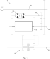
- the continuously variable transmission 10 has an input shaft 20, which is connected to the intermediate shaft 40 via at least one tooth engagement.
- the intermediate shaft 40 is connected on the one hand to an input of the variator transmission 50, and on the other hand by means of further tooth engagements to the auxiliary shaft 100, which in turn is connected to the input of the hydrostatic transmission 60.
- On an output side of the hydrostatic transmission 60 the introduction to an input of the variator transmission 50 takes place by means of a further tooth engagement.
- the variator transmission 50 is connected to an output by means of tooth engagement to the forward-reverse unit 90 and its clutch. After the forward-reverse unit 90, the power is delivered to connected modules and to the drive.
- the input shaft 20 can have a toothing on one side, which translates the power to the intermediate shaft 40.
- the translation from the intermediate to the secondary shaft 40, 100 can be carried out with a reversal of the direction of rotation, as in Figure 1 shown.
- the hydrostatic transmission 60 represents one power branch, the variator transmission 50 another.
- the power branches are summed in the variator transmission 50 and the sum is transmitted to the forward-reverse unit 90 by means of a gearing.
- the forward-reverse unit 90 switches either forward or reverse using a clutch.
- the variator transmission 50 can be designed as a planetary gear, in which case the output torque and the output speed are determined by means of superposition, i.e. by means of the speed and torque differences occurring between the two power branches.
- Figure 1 represents a so-called stick diagram in which the functional relationships of the shafts and elements are shown. Thus, the local arrangement of the shafts is not shown.
- the hydrostatic transmission 60 is provided at the lowest point in the invention, so that the output shaft 30 is arranged in a middle position.
- Figure 1 does not contradict the arrangement, but describes the functioning of the continuously variable transmission 10 in a two-dimensional representation.
- Figure 1 shows that the gearing of the input shaft 20 and the intermediate shaft 40 are arranged in one plane.
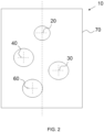
- Figure 2 describes an embodiment of the continuously variable transmission 10 with a shaft arrangement in a longitudinal view in the axial direction.
- the housing 70 encloses the individual components of the continuously variable transmission 10 at least partially.
- the housing is covered or closed by the bearing plate 80.
- the bearing plate 80 can have openings through which operating materials are introduced or mechanical connections are made.
- the bearing plate 80 can also be arranged in a completely sealing configuration, so that only mechanical connections are realized by means of shafts, wherein the shafts are sealed.
- the input shaft 20 is in the uppermost position in the installation position. With this arrangement, the distance between the input and output shafts 20, 30 can be increased in order to arrange all components on the respective shaft sections.
- the intermediate shaft 40 is arranged horizontally and vertically offset below.
- the intermediate shaft 40 includes the variator gear 50 and is connected to the input shaft 20 with a toothed engagement.
- the output shaft 30 is arranged horizontally and vertically offset from the input shaft 20 and the intermediate shaft 40 below the intermediate shaft 40.
- This arrangement has the advantage that the installation space for the variator transmission 50 and the hydrostatic transmission 60 can be optimally arranged in the housing 70. Furthermore, it is possible to arrange both transmissions 50, 60 parallel to one another.
- the hydrostatic transmission 60 is arranged in the lowest position in the installation position in the continuously variable transmission 10. The arrangement allows optimal use of installation space as well as easy maintenance access within the housing 70.
- the power path of the continuously variable transmission 10 is guided via the input shaft 20 and is divided on the intermediate shaft 40 via one or more tooth engagements between the hydrostatic transmission 60 and the variator transmission 50.
- the power path is rejoined after the hydrostatic transmission 60 in the variator transmission 50, whereby the variator transmission 50 is designed as a superposition transmission.
- the power path is then guided to the output shaft 30 via the forward-reverse clutch 90.
- the presented continuously variable transmission 10 enables a compact and, in terms of installation space length along the shaft, a short construction, which allows advantageous integration into the drive train of vehicles.
- the invention expands the application possibilities, as well as a modular structure of the drive train. Additional modules and components in a standardized design can be connected to the flat outer surfaces of the continuously variable transmission 10 with reduced effort.
- the continuously variable transmission 10 allows scaling across other model series, as well as standardization of the modules for connection.
Landscapes
- Engineering & Computer Science (AREA)
- General Engineering & Computer Science (AREA)
- Mechanical Engineering (AREA)
- Transmission Devices (AREA)
- General Details Of Gearings (AREA)
Abstract
Die Erfindung betrifft ein Stufenlosgetriebe mit einer Eingangswelle, einer Ausgangswelle, einer Zwischenwelle, einem Variatorgetriebe, einem hydrostatisches Getriebe, einem Gehäuse und einem Lagerschild, wobei das hydrostatische Getriebe in einer seitlichen Ansicht in der Einbaulage geometrisch parallel zum Variatorgetriebe angeordnet ist, und der Leistungsfluss zwischen dem hydrostatischen Getriebe und dem Variatorgetriebe aufteilbar ist, wobei die Ausgangswelle in Achsrichtung gesehen, in der Einbaulage horizontal und vertikal zur Eingangswelle versetzt ist, wobei das Gehäuse einstückig und einseitig offen ist, und die Komponenten innerhalb des Stufenlosgetriebes von dem Lagerschild im montierten Zustand im Gehäuse gehalten werden, wobei das Gehäuse und/oder der Lagerschild ebene Flächen auf den Außenseiten aufweisen, die dazu ausgebildet sind, Modulkomponenten auf einer Außenseite des Stufenlosgetriebes zu befestigen.
Description
- Die Erfindung ist ein Stufenlosgetriebe mit einer hydraulischen Komponente für den Einsatz in Fahrzeugen.
- Stufenlosgetriebe mit hydraulischen Komponenten sind in landwirtschaftlichen Fahrzeugen im Einsatz. Der Betrieb ermöglicht eine Aufteilung der Antriebsleistung über einen hydraulischen und einen mechanischen Zweig des Getriebes zusammen mit einem stufenlosen Schalten der jeweiligen Gangstufen beziehungsweise Gangbereiche. In der Landwirtschaft sind unterschiedlichen Fahranforderungen an den Antrieb gestellt. Zum einen ist das Fahren auf Kraftfahrwegen Voraussetzung für Transportarbeiten bei einem geringen bis mittleren Drehmoment. Zum anderen ist das Bearbeiten von Flächen mit Hilfe von Anbaugeräten mit einem mittleren bis hohen Drehmoment erforderlich. Hydraulische Stufenlosgetriebe haben sich in diesem Gebiet als vorteilhaft erwiesen. Wartung und Robustheit sind in diesen Bereichen von Vorteil, zusammen mit einer hohen Standzeit.
- Hydraulische Stufenlosgetriebe weisen im Allgemeinen einen Hydrostaten auf, einen Schaltbereich, sowie eine Einrichtung für das Umschalten zwischen Vorwärts- und Rückwärtsbetrieb. Um die Effizienz eines solchen Getriebes zu steigern, wird üblicherweise die Anzahl der Zahneingriffe zwischen verwendeten Zahnrädern minimiert.
- Der Bauraum des Getriebes ist durch die daran angeschlossenen Bereiche limitiert, dies trifft insbesondere auf die Baulänge in Fahrzeugrichtung solcher Getriebe zu. Gleichzeitig ist die Bauhöhe, die Erstreckung in vertikaler Richtung, ebenfalls limitiert durch Vorgaben der Achspositionen innerhalb des Getriebes in Relation zur Eingangswelle und zur Ausgangswelle, so dass eine beliebige Verkleinerung des Baumraums nicht erfolgen kann.
- Die vorliegende Erfindung löst die angesprochenen Problemstellungen, indem ein stufenloses Getriebe zur Verfügung gestellt wird, dass einen verkleinerten Bauraum aufweist. Weiterhin sind bei der Erfindung die Zahneingriffe minimiert.
- Das erfindungsgemäße Stufenlosgetriebe weist eine Eingangswelle, eine Ausgangswelle, eine Zwischenwelle, ein Variatorgetriebe, ein hydrostatisches Getriebe, ein Gehäuse und ein Lagerschild auf, wobei das Gehäuse alle Wellen und Komponenten, zumindest teilweise umschließt, und eine Eingangsseite zur Leistungseinleitung und eine Ausgangsseite zur Leistungsabgabe aufweist, wobei das Stufenlosgetriebe eine Einbaulage aufweist, die im Betrieb vorgesehen ist, wobei die Eingangswelle über einen oder mehrere Zahneingriffe mittels Zahnrädern mit der Zwischenwelle verbunden ist, wobei auf der Zwischenwelle das Variatorgetriebe angeordnet ist, wobei die Zwischenwelle über einen oder mehrere Zahneingriffe mit der Ausgangswelle verbunden ist, wobei das hydrostatische Getriebe in einer seitlichen Ansicht in der Einbaulage geometrisch parallel zum Variatorgetriebe angeordnet ist, und der Leistungsfluss zwischen dem hydrostatischen Getriebe und dem Variatorgetriebe aufteilbar ist, wobei die Ausgangswelle in Achsrichtung gesehen, in der Einbaulage horizontal und vertikal zur Eingangswelle versetzt ist, wobei das Gehäuse einstückig und einseitig offen ist, und die Komponenten innerhalb des Stufenlosgetriebes von dem Lagerschild im montierten Zustand im Gehäuse gehalten werden, wobei das Gehäuse und/oder der Lagerschild ebene Flächen auf der Eingangs- und/oder Ausgangsseite aufweisen, die dazu ausgebildet sind, Modulkomponenten auf einer Außenseite des Stufenlosgetriebes zu befestigen.
- Die Eingangswelle leitet die Antriebsleistung von der Antriebswelle in das Stufenlosgetriebe. Über die Zwischenwelle und die Ausgangswelle wird die Antriebsleistung an angeschlossene Module abgegeben. Das Variatorgetriebe ist mittels Zahnradkopplungen und Kupplungen in der Lage unterschiedliche Geschwindigkeitsbereiche für den Antrieb des Fahrzeugs zur Verfügung zu stellen. Das hydrostatische Getriebe innerhalb des Stufenlosgetriebes stellt einen Leistungszweig dar, über den ein Teil der Leistung parallel zum Variatorgetriebe geleitet wird. Durch die Erfindung wird somit eine kompakte Ausbildung eines Stufenlosgetriebes ermöglicht, bei einer verkürzten Baulänge. Durch den Versatz und die geometrisch parallele, also in der Einbaulage auf dem gleichen Abschnitt in der Längsrichtung der Wellen, wird zusätzlicher Bauraum in der Länge eingespart und kann somit für weitere Module, etwa eine Schmierstoffversorgung oder einen Allradantrieb verwendet werden.
- In einer Weiterbildung weist die Ausgangswelle (30) eine Vorwärts-Rückwärtskupplung (90) auf.
- Durch das Vorsehen der Vorwärts-Rückwärtskupplung auf der Ausgangswelle kann weiter Bauraum in der Länge des Getriebes eingespart werden.
- Bei einer weiteren Ausbildung der Erfindung weist die Ausgangswelle eine Vorwärtskupplung und die Zwischenwelle eine Rückwärtskupplung auf.
- Die Anordnung ermöglicht die platzsparende Unterbringung der Rückwärtskupplung und dem damit verbundenen Zwischenzahnrad zur Drehrichtungsumkehr.
- In einer Weiterbildung weist die Ausgangswelle eine Rückwärtskupplung und die Zwischenwelle eine Vorwärtskupplung auf.
- Die Anordnung ermöglicht die platzsparende Unterbringung der Rückwärtskupplung und dem damit verbundenen Zwischenzahnrad zur Drehrichtungsumkehr.
- Bei einer weiteren Ausbildung der Erfindung ist das Variatorgetriebe ein Umlaufrädergetriebe und/oder ein Überlagerungsgetriebe.
- Die Ausbildung als Umlaufrädergetriebe ermöglicht einen kleinen Bauraum bei gleichzeitig hoher Spreizung des Getriebes. Das Umlaufrädergetriebe hat durch die minimal erforderlichen Zahneingriffe eine hohe Effizienz. Durch die Ausführung als Überlagerungsgetriebe kann das hydrostatische Getriebe und dessen Leistungsausgang als weiterer Eingang für das Variatorgetriebe verwendet werden.
- In einer Weiterbildung weist das Stufenlosgetriebe eine Nebenwelle auf. Die Nebenwelle kann für die Anordnung des hydrostatischen Getriebes verwendet werden.
- Bei einer weiteren Ausbildung der Erfindung ist die Zwischenwelle über ein oder zwei Zahneingriffe mit einem Eingang des hydrostatischen Getriebes verbunden, ein Ausgang des hydrostatischen Getriebes mit einem Eingang des Variatorgetriebes mittels eines Zahneingriffs verbunden.
- Die Minimierung der notwendigen Zahneingriffe verbessert die Effizienz des Stufenlosgetriebes und die Auswirkung auf die Geräuschentwicklung und den Fahrkomfort.
- In einer Weiterbildung ist Ausgangswelle kürzer als die Eingangswelle und in Achsrichtung in der Einbaulage versetzt zur Eingangswelle angeordnet.
- Die Verkürzung der Ausgangswelle verringert den Bauraum in Längsrichtung des Stufenlosgetriebes. Die Versetzung der Ausgangswelle führt dazu, dass sämtliche Zahnräder der Eingangs- und Ausgangswelle auf einer senkrechten Ebene liegen, entweder mit einer Zahnflanke oder mit den Mitten der Zahnbreite. Durch die Anordnung wird ein einheitliches Maß zur Lagerung der Zahnräder und der Welle im Lagerschild ermöglicht. Das Lagerschild ist somit in einer flachen Form ausführbar ohne Vorsprünge. Dies führt wiederrum zu Materialersparnis, Gewichtsreduktion und zu einer robusten Abdichtung zwischen Gehäuse und Lagerschild, da eine komplizierte Dichtungsgeometrie vermieden wird.
- Nach einer Ausführung ist das hydrostatische Getriebe (60) in einer Einbaulage in der untersten Position unter allen anderen Wellen angeordnet.
- Die Anordnung des hydrostatischen Getriebes an unterster Position in der Einbaulage erlaubt eine Raumaufteilung, bei der die Eingangswelle und die Ausgangswelle in einer höheren Position angeordnet sind und gleichzeitig zueinander in eine horizontale und vertikale Richtung versetzt sind. Mittels dieser Anordnung kann der nötige Bauraum in der Länge stark reduziert werden, da die einzelnen Komponenten parallel angeordnet sind.
- Bei einer weiteren Ausbildung der Erfindung liegen die angeordneten Zahnräder auf einer Seite im Inneren des Gehäuses in der Einbaulage in Längsrichtung mit der Zahnflanke auf der gleichen Ebene, oder mit der Mitte der jeweiligen Zahnbreite auf einer gemeinsamen Ebene, die senkrecht zu den Wellen liegt.
- Die Ausrichtung aller Zahnräder auf einer Seite des Getriebes in Querrichtung gesehen, bietet die Möglichkeit, eine gemeinsame Lagerung im Lagerschild des Gehäuses auszubilden. Die Anordnung ermöglicht einen ebenen Abschluss für den Lagerschild, so dass dieser ebenfalls mit einer durchgehenden Ebene ausgestattet ist. Dies ist besonders vorteilhaft zum weiteren Anschluss von Modulen an das Stufenlosgetriebe.
- In einer Weiterbildung ist die Eingangswelle in einer seitlichen Ansicht in der Einbaulage an oberster Position über allen anderen Wellen angeordnet.
- Die Anordnung an oberster Position zusammen mit dem hydrostatischen Getriebe in der untersten Position ermöglicht es, Bauraum einzusparen und erlaubt die kompakte Anordnung von hydrostatischem Getriebe und Variatorgetriebe in einer parallelen Ausführung. Die Gesamtlänge des Stufenlosgetriebes ist reduziert und insgesamt wird weniger Material verwendet.
- Bei einer weiteren Ausbildung der Erfindung ist der Lagerschild offen oder geschlossen ausgeführt.
- In der offenen Ausführung kann der Lagerschild Öffnungen aufweisen zum Durchleiten von Betriebsstoffen, z.B. Schmierstoff. Ebenfalls können Öffnungen für hydraulische Leitungen vorgesehen werden, sowie für elektrische Leitungen oder sogar für mechanische Wellen oder Anschlüsse. Die Ausführung ermöglicht den direkten Anschluss weiterer Funktionsmodule an das Gehäuse bzw. den Lagerschild des Stufenlosgetriebes.
- Weitere Ausführungen der Erfindung werden anhand der Figuren beschrieben. Dabei zeigt
-
Figur 1 ein Diagramm des stufenlosen Getriebes; -
Figur 2 eine Ansicht in Querrichtung der Einbaulage mit den Positionen der Wellen im stufenlosen Getriebe. - Das Stufenlosgetriebe 10 weist eine Eingangswelle 20 auf, die über wenigstens einen Zahneingriff mit der Zwischenwelle 40 verbunden ist. Die Zwischenwelle 40 ist einerseits mit einem Eingang des Variatorgetriebes 50 verbunden, andererseits mittels weiteren Zahneingriffen mit der Nebenwelle 100, die wiederrum mit dem Eingang des hydrostatischen Getriebes 60 verbunden ist. Auf einer Ausgangsseite des hydrostatischen Getriebes 60 erfolgt mittels einem weiteren Zahneingriff die Einleitung in einen Eingang des Variatorgetriebes 50. Das Variatorgetriebe 50 ist mit einem Ausgang mittels Zahneingriff mit der Vorwärts-Rückwärts-Einheit 90 und deren Kupplung verbunden. Nach der Vorwärts-Rückwärts Einheit 90 erfolgt die Leistungsabgabe an angeschlossene Module und an den Fahrantrieb.
- Die Eingangswelle 20 kann weist auf einer Seite eine Verzahnung auf, die die Leistung an die Zwischenwelle 40 übersetzt. Die Übersetzung von der Zwischen- auf die Nebenwelle 40, 100 kann mit einer Drehrichtungsumkehr erfolgen, wie in
Figur 1 gezeigt. Das hydrostatische Getriebe 60 stellt einen Leistungszweig dar, das Variatorgetriebe 50 einen weiteren. Die Leistungszweige werden im Variatorgetriebe 50 summiert und die Summe mittels einer Verzahnung an die Vorwärts-Rückwärts-Einheit 90 abgegeben. Die Vorwärts-Rückwärts-Einheit 90 schaltet durch eine Kupplung entweder die Vorwärts- oder die Rückwärtsfahrt. - Das Variatorgetriebe 50 kann als Umlaufgetriebe ausgeführt sein, wobei hier mittels Überlagerung, das heißt durch die auftretenden Drehzahl- und Drehmomentunterschiede der beiden Leistungszweige, das Ausgangsmoment und die Ausgangsdrehzahl festgelegt werden.
-
Figur 1 stellt ein sogenanntes Stick-Diagramm dar, bei welchem die funktionalen Zusammenhänge der Wellen und Elemente wiedergegeben werden. Somit ist die lokale Anordnung der Wellen nicht dargestellt. Das hydrostatische Getriebe 60 ist in der Erfindung an unterster Stelle vorgesehen, so dass die Ausgangswelle 30 in einer mittleren Position angeordnet ist.Figur 1 steht der Anordnung nicht entgegen, sondern beschreibt die Funktionsweise des Stufenlosgetriebes 10 in einer zweidimensionalen Wiedergabe. -
Figur 1 zeigt, dass die Verzahnung von der Eingangswelle 20 und der Zwischenwelle 40 in einer Ebene angeordnet sind. -
Figur 2 beschreibt ein Ausführungsbeispiel des Stufenlosgetriebes 10 mit einer Wellenanordnung in einer Längssicht in Achsrichtung. Das Gehäuse 70 umschließt die einzelnen Komponenten des Stufenlosgetriebes 10 zumindest teilweise. Das Gehäuse wird durch den Lagerschild 80 abgedeckt oder verschlossen. Der Lagerschild 80 kann Öffnungen aufweisen, durch welche Betriebsstoffe eingeleitet werden oder mechanische Verbindungen hergestellt werden. Der Lagerschild 80 kann auch in einer vollständig abdichtenden Ausbildung angeordnet sein, so dass lediglich mechanische Verbindungen mittels Wellen realisiert sind, wobei die Wellen abgedichtet sind. - Die Eingangswelle 20 befindet sich in der Einbaulage in der obersten Position. Mit dieser Anordnung kann der Abstand zwischen der Eingangs- und der Ausgangswelle 20, 30 vergrößert werden, um alle Komponenten auf den jeweiligen Wellenabschnitten anzuordnen. Horizontal und vertikal versetzt darunter ist die Zwischenwelle 40 angeordnet. Die Zwischenwelle 40 umfasst das Variatorgetriebe 50 und ist mit einem Zahneingriff mit der Eingangswelle 20 verbunden.
- Die Ausgangswelle 30 ist zur Eingangswelle 20 und zur Zwischenwelle 40 horizontal und vertikal versetzt unterhalb der Zwischenwelle 40 angeordnet. Diese Anordnung hat den Vorteil, dass der Bauraum für das Variatorgetriebe 50, als auch für das hydrostatische Getriebe 60 optimal im Gehäuse 70 angeordnet werden kann. Weiterhin ist es dadurch möglich, beide Getriebe 50, 60 parallel zueinander anzuordnen.
- Das hydrostatische Getriebe 60 ist in der untersten Position in der Einbaulage im Stufenlosgetriebe 10 angeordnet. Die Anordnung erlaubt eine optimale Bauraumausnutzung, sowie einen einfachen Wartungszugang innerhalb des Gehäuses 70.
- Der Leistungspfad des Stufenlosgetriebes 10 wird über die Eingangswelle 20 geführt und teilt sich auf der Zwischenwelle 40 über ein oder mehrere Zahneingriffe zwischen dem hydrostatischen Getriebe 60 und dem Variatorgetriebe 50 auf. Der Leistungspfad wird nach dem hydrostatischen Getriebe 60 im Variatorgetriebe 50 wieder zusammengeführt, wobei das Variatorgetriebe 50 als Überlagerungsgetriebe ausgeführt ist. Der Leistungspfad wird dann über die Vorwärts-Rückwärts-Kupplung 90 an die Ausgangswelle 30 geführt.
- Das vorgestellte Stufenlosgetriebe 10 ermöglicht eine kompakte und in Bauraumlänge entlang der Welle gesehen, eine kurze Konstruktion, die eine vorteilhafte Integration in den Antriebsstrang von Fahrzeugen ermöglicht. Durch die Erfindung werden die Anwendungsmöglichkeiten erweitert, sowie ein modularer Aufbau des Antriebsstrangs. An die ebenen Außenflächen des Stufenlosgetriebes 10 können mit verringertem Aufwand weitere Module und Komponenten in einer standardisierten Ausführung angeschlossen werden. Das Stufenlosgetriebe 10 erlaubt eine Skalierung über weitere Modellreihen, sowie eine Standardisierung der Module zum Anschluss.
Claims (12)
- Stufenlosgetriebe (10) aufweisendeine Eingangswelle (20),eine Ausgangswelle (30),eine Zwischenwelle (40),ein Variatorgetriebe (50),ein hydrostatisches Getriebe (60),ein Gehäuse (70) und ein Lagerschild (80), wobei das Gehäuse (70) alle Wellen und Komponenten zumindest teilweise umschließt, und eine Eingangsseite zur Leistungseinleitung und eine Ausgangsseite zur Leistungsabgabe aufweist, wobei das Stufenlosgetriebe (10) eine Einbaulage aufweist, die im Betrieb vorgesehen ist,wobei die Eingangswelle (20) über einen oder mehrere Zahneingriffe mittels Zahnrädern mit der Zwischenwelle (40) verbunden ist,wobei auf der Zwischenwelle (40) das Variatorgetriebe (50) angeordnet ist, wobei die Zwischenwelle (40) über einen oder mehrere Zahneingriffe mit der Ausgangswelle (30) verbunden ist,wobei das hydrostatische Getriebe (60) in einer seitlichen Ansicht in der Einbaulage geometrisch parallel zum Variatorgetriebe (50) angeordnet ist, und der Leistungsfluss zwischen dem hydrostatischen Getriebe (60) und dem Variatorgetriebe (50) aufteilbar ist,wobei die Ausgangswelle (30) in Achsrichtung gesehen, in der Einbaulage horizontal und vertikal zur Eingangswelle (20) versetzt ist,wobei das Gehäuse (70) einstückig und einseitig offen ist, und die Komponenten innerhalb des Stufenlosgetriebes (10) von dem Lagerschild (80) im montierten Zustand im Gehäuse (70) gehalten werden,wobei das Gehäuse (70) und/oder der Lagerschild (80) ebene Flächen auf den Außenseiten aufweisen, die dazu ausgebildet sind, Modulkomponenten auf einer Außenseite des Stufenlosgetriebes (10) zu befestigen.
- Stufenlosgetriebe (10) nach Anspruch 1, dadurch gekennzeichnet, dass die Ausgangswelle (30) eine Vorwärts-Rückwärtskupplung (90) aufweist.
- Stufenlosgetriebe (10) nach Anspruch 1, dadurch gekennzeichnet, dass die Ausgangswelle (30) eine Vorwärtskupplung und die Zwischenwelle (40) eine Rückwärtskupplung aufweist.
- Stufenlosgetriebe (10) nach Anspruch 1, dadurch gekennzeichnet, dass die Ausgangswelle (30) eine Rückwärtskupplung und die Zwischenwelle (40) eine Vorwärtskupplung aufweist.
- Stufenlosgetriebe (10) nach einem der vorangehenden Ansprüche, dadurch gekennzeichnet, dass das Variatorgetriebe (50) ein Umlaufrädergetriebe und/oder ein Überlagerungsgetriebe ist.
- Stufenlosgetriebe (10) nach einem der vorangehenden Ansprüche, dadurch gekennzeichnet, dass das Stufenlosgetriebe (10) eine Nebenwelle aufweist.
- Stufenlosgetriebe (10) nach einem der vorangehenden Ansprüche, dadurch gekennzeichnet, dass die Zwischenwelle (40) über ein oder zwei Zahneingriffe mit der mit einem Eingang eines hydrostatischen Getriebes (60) verbunden ist, ein Ausgang des hydrostatischen Getriebes (60) mit einem Eingang des Variatorgetriebes (60) mittels eines Zahneingriffs verbunden ist.
- Stufenlosgetriebe (10) nach einem der vorangehenden Ansprüche, dadurch gekennzeichnet, dass Ausgangswelle (30) kürzer ist als die Eingangswelle (20) und in Achsrichtung in der Einbaulage versetzt zur Eingangswelle (20) angeordnet ist.
- Stufenlosgetriebe (10) nach einem der vorangehenden Ansprüche, dadurch gekennzeichnet, dass das hydrostatische Getriebe (60) in einer Einbaulage in der untersten Position unter allen anderen Wellen angeordnet ist.
- Stufenlosgetriebe (10) nach einem der vorangehenden Ansprüche, dadurch gekennzeichnet, dass die angeordneten Zahnräder auf einer Seite im Inneren des Gehäuses (70) in der Einbaulage mit der Zahnflanke auf der gleichen Ebene liegen, oder mit der Mitte der jeweiligen Zahnbreite auf einer gemeinsamen Ebene liegen, die senkrecht zu den Wellen liegt.
- Stufenlosgetriebe (10) nach einem der vorangehenden Ansprüche, dadurch gekennzeichnet, dass die Eingangswelle (20) in einer seitlichen Ansicht in der Einbaulage an oberster Position über allen anderen Wellen angeordnet ist.
- Stufenlosgetriebe (10) nach einem der vorangehenden Ansprüche, dadurch gekennzeichnet, dass der Lagerschild (80) offen oder geschlossen ausgeführt ist.
Priority Applications (3)
| Application Number | Priority Date | Filing Date | Title |
|---|---|---|---|
| EP23194857.1A EP4517133A1 (de) | 2023-09-01 | 2023-09-01 | Stufenlosgetriebe |
| CN202410995270.4A CN119554389A (zh) | 2023-09-01 | 2024-07-24 | 无级变速器 |
| US18/814,973 US12529416B2 (en) | 2023-09-01 | 2024-08-26 | Continuously variable transmission |
Applications Claiming Priority (1)
| Application Number | Priority Date | Filing Date | Title |
|---|---|---|---|
| EP23194857.1A EP4517133A1 (de) | 2023-09-01 | 2023-09-01 | Stufenlosgetriebe |
Publications (1)
| Publication Number | Publication Date |
|---|---|
| EP4517133A1 true EP4517133A1 (de) | 2025-03-05 |
Family
ID=87929070
Family Applications (1)
| Application Number | Title | Priority Date | Filing Date |
|---|---|---|---|
| EP23194857.1A Withdrawn EP4517133A1 (de) | 2023-09-01 | 2023-09-01 | Stufenlosgetriebe |
Country Status (3)
| Country | Link |
|---|---|
| US (1) | US12529416B2 (de) |
| EP (1) | EP4517133A1 (de) |
| CN (1) | CN119554389A (de) |
Citations (2)
| Publication number | Priority date | Publication date | Assignee | Title |
|---|---|---|---|---|
| US20100051410A1 (en) * | 2008-08-29 | 2010-03-04 | Koji Iwaki | Traveling System Transmission Structure for Vehicle |
| EP2193289A1 (de) * | 2007-10-02 | 2010-06-09 | ZF Friedrichshafen AG | Stufenlose getriebevorrichtung für ein fahrzeug |
Family Cites Families (12)
| Publication number | Priority date | Publication date | Assignee | Title |
|---|---|---|---|---|
| US5888162A (en) * | 1992-10-06 | 1999-03-30 | J.C. Bamford Excavators Limited | Infinitely variable transmission with power splitting |
| DE19512637A1 (de) * | 1995-04-05 | 1996-10-10 | Claas Ohg | Antriebseinheit, Verfahren zu deren Steuerung und Verwendung derselben |
| US5868640A (en) * | 1996-12-04 | 1999-02-09 | Caterpillar Inc. | Hydromechanical transmission having four members and two planetaries |
| US6565471B2 (en) * | 2000-12-19 | 2003-05-20 | Case Corporation | Continuously variable hydro-mechanical transmission |
| AT11366U1 (de) * | 2009-06-04 | 2010-09-15 | Dieter Ing Stoeckl | Überlagerungsgetriebe |
| US8523724B2 (en) * | 2010-11-24 | 2013-09-03 | Caterpillar Inc. | Method of synchronizing in split torque continuously variable dual clutch transmission |
| US8808131B2 (en) * | 2012-02-28 | 2014-08-19 | Caterpillar Inc. | Multi-range hydro-mechanical transmission |
| US8961347B2 (en) * | 2012-04-18 | 2015-02-24 | Caterpillar Inc. | Cold start clutch for CVT transmission |
| GB201223536D0 (en) * | 2012-12-21 | 2013-02-13 | Agco Int Gmbh | Agricultural vehicle transmission |
| US20210041021A1 (en) * | 2019-08-07 | 2021-02-11 | Caterpillar Inc. | Multi-variator hydrostatic transmission |
| JP7419064B2 (ja) * | 2019-12-27 | 2024-01-22 | 株式会社クボタ | 作業車両 |
| US11773970B2 (en) * | 2021-09-27 | 2023-10-03 | Dana Italia S.R.L. | Hydromechanical transmission and control method |
-
2023
- 2023-09-01 EP EP23194857.1A patent/EP4517133A1/de not_active Withdrawn
-
2024
- 2024-07-24 CN CN202410995270.4A patent/CN119554389A/zh active Pending
- 2024-08-26 US US18/814,973 patent/US12529416B2/en active Active
Patent Citations (2)
| Publication number | Priority date | Publication date | Assignee | Title |
|---|---|---|---|---|
| EP2193289A1 (de) * | 2007-10-02 | 2010-06-09 | ZF Friedrichshafen AG | Stufenlose getriebevorrichtung für ein fahrzeug |
| US20100051410A1 (en) * | 2008-08-29 | 2010-03-04 | Koji Iwaki | Traveling System Transmission Structure for Vehicle |
Also Published As
| Publication number | Publication date |
|---|---|
| US20250075783A1 (en) | 2025-03-06 |
| US12529416B2 (en) | 2026-01-20 |
| CN119554389A (zh) | 2025-03-04 |
Similar Documents
| Publication | Publication Date | Title |
|---|---|---|
| EP0204728B1 (de) | Kraftübertragungsaggregat zum antrieb einer drehzahlvariablen arbeitsmaschine | |
| DE3622045C2 (de) | ||
| DE102006015661A1 (de) | Lastschaltbares Getriebe für ein Nutzfahrzeug | |
| DE2525888B2 (de) | Leistungsverzweigende Getriebeanordnung | |
| DE4238256A1 (de) | ||
| WO2009068484A1 (de) | Stirnradgetriebe | |
| EP2487385A2 (de) | Geschwindigkeits-Wechselgetriebe für Kraftfahrzeuge | |
| DE1630852C3 (de) | Aus Brennkraftmaschine und hydrodynamisch-mechanischem Getriebe bestehender Antriebsblock für Fahrzeuge | |
| DE3607602A1 (de) | Antriebsanordnung, insbesondere fuer gelaendegaengige kraftfahrzeuge | |
| EP0552673A1 (de) | Kraftfahrzeuggetriebe | |
| DE69620605T2 (de) | Hydromechanisches getriebe | |
| DE102020112624A1 (de) | Getriebeeinrichtung für einen elektrischen Antrieb eines Fahrzeuges | |
| DE6901095U (de) | Kraftuebertragungsvorrichtung fuer kraftfahrzeuge | |
| DE4224850A1 (de) | Wolfrom-Planetengetriebe | |
| DE102020117269B3 (de) | Getriebeanordnung | |
| DE202023003031U1 (de) | Stufenlosgetriebe | |
| DE2355171B2 (de) | Mehrwandlergetriebe für Fahrzeuge | |
| EP1664592A1 (de) | Getriebebaueinheit | |
| AT514150B1 (de) | Getriebeanordnung für Kraftfahrzeuge | |
| DE4104170C2 (de) | Hydrodynamisch-mechanisches Lastschaltgetriebe in Vorgelegebauweise | |
| EP1297271B1 (de) | Hydrodynamisches 2-gang-turbogetriebe | |
| DE3912386C2 (de) | Stufenlos hydrostatisch-mechanisches Leistungsverzweigungsgetriebe | |
| DE3620250A1 (de) | Lastschaltgetriebe fuer fahrzeuge | |
| EP3434550B1 (de) | Antriebsanordnung | |
| DE202022104125U1 (de) | Leistungsverzweigungsgetriebe |
Legal Events
| Date | Code | Title | Description |
|---|---|---|---|
| PUAI | Public reference made under article 153(3) epc to a published international application that has entered the european phase |
Free format text: ORIGINAL CODE: 0009012 |
|
| STAA | Information on the status of an ep patent application or granted ep patent |
Free format text: STATUS: THE APPLICATION HAS BEEN PUBLISHED |
|
| AK | Designated contracting states |
Kind code of ref document: A1 Designated state(s): AL AT BE BG CH CY CZ DE DK EE ES FI FR GB GR HR HU IE IS IT LI LT LU LV MC ME MK MT NL NO PL PT RO RS SE SI SK SM TR |
|
| STAA | Information on the status of an ep patent application or granted ep patent |
Free format text: STATUS: THE APPLICATION IS DEEMED TO BE WITHDRAWN |
|
| 18D | Application deemed to be withdrawn |
Effective date: 20250906 |